EP3029343A1 - Tilting pad bearing and turbo compressor - Google Patents
Tilting pad bearing and turbo compressor Download PDFInfo
- Publication number
- EP3029343A1 EP3029343A1 EP14832859.4A EP14832859A EP3029343A1 EP 3029343 A1 EP3029343 A1 EP 3029343A1 EP 14832859 A EP14832859 A EP 14832859A EP 3029343 A1 EP3029343 A1 EP 3029343A1
- Authority
- EP
- European Patent Office
- Prior art keywords
- tilting
- pad
- rotary shaft
- lubricating oil
- pad bearing
- Prior art date
- Legal status (The legal status is an assumption and is not a legal conclusion. Google has not performed a legal analysis and makes no representation as to the accuracy of the status listed.)
- Granted
Links
Images


Classifications
-
- F—MECHANICAL ENGINEERING; LIGHTING; HEATING; WEAPONS; BLASTING
- F16—ENGINEERING ELEMENTS AND UNITS; GENERAL MEASURES FOR PRODUCING AND MAINTAINING EFFECTIVE FUNCTIONING OF MACHINES OR INSTALLATIONS; THERMAL INSULATION IN GENERAL
- F16C—SHAFTS; FLEXIBLE SHAFTS; ELEMENTS OR CRANKSHAFT MECHANISMS; ROTARY BODIES OTHER THAN GEARING ELEMENTS; BEARINGS
- F16C33/00—Parts of bearings; Special methods for making bearings or parts thereof
- F16C33/02—Parts of sliding-contact bearings
- F16C33/04—Brasses; Bushes; Linings
- F16C33/06—Sliding surface mainly made of metal
- F16C33/10—Construction relative to lubrication
- F16C33/1025—Construction relative to lubrication with liquid, e.g. oil, as lubricant
- F16C33/106—Details of distribution or circulation inside the bearings, e.g. details of the bearing surfaces to affect flow or pressure of the liquid
- F16C33/1085—Channels or passages to recirculate the liquid in the bearing
-
- F—MECHANICAL ENGINEERING; LIGHTING; HEATING; WEAPONS; BLASTING
- F04—POSITIVE - DISPLACEMENT MACHINES FOR LIQUIDS; PUMPS FOR LIQUIDS OR ELASTIC FLUIDS
- F04D—NON-POSITIVE-DISPLACEMENT PUMPS
- F04D29/00—Details, component parts, or accessories
- F04D29/04—Shafts or bearings, or assemblies thereof
- F04D29/046—Bearings
-
- F—MECHANICAL ENGINEERING; LIGHTING; HEATING; WEAPONS; BLASTING
- F16—ENGINEERING ELEMENTS AND UNITS; GENERAL MEASURES FOR PRODUCING AND MAINTAINING EFFECTIVE FUNCTIONING OF MACHINES OR INSTALLATIONS; THERMAL INSULATION IN GENERAL
- F16C—SHAFTS; FLEXIBLE SHAFTS; ELEMENTS OR CRANKSHAFT MECHANISMS; ROTARY BODIES OTHER THAN GEARING ELEMENTS; BEARINGS
- F16C17/00—Sliding-contact bearings for exclusively rotary movement
- F16C17/02—Sliding-contact bearings for exclusively rotary movement for radial load only
- F16C17/03—Sliding-contact bearings for exclusively rotary movement for radial load only with tiltably-supported segments, e.g. Michell bearings
-
- F—MECHANICAL ENGINEERING; LIGHTING; HEATING; WEAPONS; BLASTING
- F16—ENGINEERING ELEMENTS AND UNITS; GENERAL MEASURES FOR PRODUCING AND MAINTAINING EFFECTIVE FUNCTIONING OF MACHINES OR INSTALLATIONS; THERMAL INSULATION IN GENERAL
- F16C—SHAFTS; FLEXIBLE SHAFTS; ELEMENTS OR CRANKSHAFT MECHANISMS; ROTARY BODIES OTHER THAN GEARING ELEMENTS; BEARINGS
- F16C33/00—Parts of bearings; Special methods for making bearings or parts thereof
- F16C33/02—Parts of sliding-contact bearings
- F16C33/04—Brasses; Bushes; Linings
- F16C33/06—Sliding surface mainly made of metal
- F16C33/10—Construction relative to lubrication
- F16C33/1025—Construction relative to lubrication with liquid, e.g. oil, as lubricant
- F16C33/1045—Details of supply of the liquid to the bearing
-
- F—MECHANICAL ENGINEERING; LIGHTING; HEATING; WEAPONS; BLASTING
- F16—ENGINEERING ELEMENTS AND UNITS; GENERAL MEASURES FOR PRODUCING AND MAINTAINING EFFECTIVE FUNCTIONING OF MACHINES OR INSTALLATIONS; THERMAL INSULATION IN GENERAL
- F16C—SHAFTS; FLEXIBLE SHAFTS; ELEMENTS OR CRANKSHAFT MECHANISMS; ROTARY BODIES OTHER THAN GEARING ELEMENTS; BEARINGS
- F16C2360/00—Engines or pumps
- F16C2360/44—Centrifugal pumps
Definitions
- the present invention relates to a tilting-pad bearing and a turbo compressor.
- a rotary shaft of a turbo compressor is rotatably supported by a tilting-pad bearing including tilting pads which are supported by a housing of the bearing so as to be tiltable.
- a tilting-pad bearing is a kind of slide bearing in which a rotary shaft is slidably supported by a plurality of tilting pads arranged annularly around the rotary shaft.
- the tilting pad is heated due to sliding friction during rotation of the rotary shaft. Therefore, for example, in Patent Documents 1 to 3, the inside of the tilting pad is provided with an internal flow passageway through which lubricating oil flows, the lubricating oil being used for reducing rotation resistance (sliding friction) of the rotary shaft, and cooling for the tilting pad is performed by lubricating oil flowing through the flow passageway.
- Patent Documents 4 and 5 disclose a tilting-pad bearing which includes a plurality of tilting pads, a housing that holds the tilting pads, and a pair of side plates that are provided on two sides of the tilting pad.
- the housing is provided with an oil supply passageway which supplies lubricating oil into a gap between the tilting pads disposed next to each other, and the side plate is provided with a notch (an oil discharge hole) which discharges lubricating oil.
- the capacity of a turbo compressor has been increased, and the size of a tilting-pad bearing has also been increased. If the size of the tilting-pad bearing is increased, the size of a tilting pad is also naturally increased. If the size of the tilting pad is increased, since the sliding surface of the tilting pad facing the rotary shaft is expanded or the heat capacity of the tilting pad is increased, further efficient cooling for the tilting pad may be required.
- the present invention has been made in view of the above circumstances, and an object thereof is to improve the cooling efficiency of a tilting pad included in a tilting-pad bearing.
- the present invention adopts the following configurations as means to solve the above problems.
- a first aspect of the present invention is a tilting-pad bearing including: a plurality of tilting pads arranged annularly around a rotary shaft so as to form a gap therebetween; a housing accommodating and supporting the plurality of tilting pads from outside in the radial direction of the rotary shaft and including a lubricating oil-supplying hole provided at a position facing the gap formed between the tilting pads disposed next to each other; and a pair of side plates disposed so that the tilting pads are interposed between the side plates in the axial direction of the rotary shaft.
- a second aspect of the present invention is that in the tilting-pad bearing of the first aspect, a gap is formed between a side plate and an outer circumferential surface of the rotary shaft, and exposes at least part of the discharge opening of the tilting pad to outside of the tilting-pad bearing.
- a third aspect of the present invention is that in the tilting-pad bearing of the first or second aspect, a side plate is divided into parts, and a gap is provided between the parts disposed next to each other.
- a fifth aspect of the present invention is that in the tilting-pad bearing of any one of the first to fourth aspects, the opening area of the second inflow opening is greater than that of the first inflow opening.
- a sixth aspect of the present invention is a turbo compressor including: an impeller; and a rotary shaft connected to the impeller.
- the tilting-pad bearing according to any one of claims 1 to 5 rotatably supports the rotary shaft.
- an internal flow passageway provided in a tilting pad includes: a first inflow opening which opens at a leading side of the tilting pad in the rotation direction of a rotary shaft; and a second inflow opening which opens at a trailing side of the tilting pad in the rotation direction of the rotary shaft. Therefore, in the present invention, lubricating oil flows into the inside of the tilting pad from both of the leading side and the trailing side of the tilting pad in the rotation direction of the rotary shaft. Thus, a large amount of lubricating oil can be imported into the inside of the tilting pad.
- FIG. 1 is a partial cross-sectional view showing part of a turbo compressor 100 including a tilting-pad bearing 1 of this embodiment.
- the turbo compressor 100 includes an impeller 200 and a rotary shaft 300 whose one end is connected with the impeller 200 and whose middle part is provided with a gear 301, and the tilting-pad bearing 1 of this embodiment rotatably supports the rotary shaft 300.
- FIG. 1 shows two tilting-pad bearings 1 which rotatably support the rotary shaft 300.
- An air seal 400 and an oil seal 500 are provided between the impeller 200 and the tilting-pad bearing 1 positioned to be close to the impeller 200.
- the turbo compressor 100 is a two-stage compressor.
- the tilting-pad bearing 1, the impeller 200, the air seal 400 and the oil seal 500 are provided in each of two end portions of the rotary shaft 300.
- FIG. 1 shows the impeller 200, the air seal 400 and the oil seal 500 which are positioned in the right end portion of the rotary shaft 300, and omits the impeller 200, the air seal 400 and the oil seal 500 which are positioned on the left side of the rotary shaft 300.
- FIG. 1 also omits a housing and a driving mechanism, the housing accommodating the impellers 200 and the like and being provided with flow passageways for air (a fluid to be compressed), the driving mechanism being configured to rotationally drive the rotary shaft 300.
- FIG. 1 also omits a housing and a driving mechanism, the housing accommodating the impellers 200 and the like and being provided with flow passageways for air (a fluid to be compressed), the driving mechanism being configured to rotationally drive the rotary shaft 300.
- FIG. 1 shows a state where a quarter of the tilting-pad bearing 1 in the circumferential direction around the rotary shaft 300 is cut out from the tilting-pad bearing 1. That is, FIG. 1 shows a side view of the tilting-pad bearing 1 including a cross-sectional view of part of the tilting-pad bearing 1.
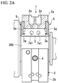
- FIG. 2A is a side view of the tilting-pad bearing 1 of this embodiment
- FIG. 2B is a front view of the tilting-pad bearing 1 of this embodiment
- FIGS. 2A and 2B show partial cross-sectional views of the tilting-pad bearing 1 obtained by cutting out part thereof in order to improve the visibility of the internal structure of the tilting-pad bearing 1.
- the tilting-pad bearing 1 of this embodiment includes a housing 2, a plurality of tilting pads 3, a fixing pin 4 provided on each tilting pad 3, and two side plates 5.
- the housing 2 is an annular member accommodating and supporting the plurality of tilting pads 3 from outside in the radial direction of the rotary shaft 300. As shown in FIG. 2B , the housing 2 includes an upper-side portion 2a and a lower-side portion 2b which are capable of being separated from each other in the vertical direction, a positioning pin 2c which positions the upper-side portion 2a and the lower-side portion 2b, and a bolt 2d which fastens the upper-side portion 2a and the lower-side portion 2b.
- the housing 2 is provided with lubricating oil-supplying holes 2e which penetrate the housing 2 from the outer circumferential surface to the inner circumferential surface thereof.
- the lubricating oil-supplying holes 2e guide toward the rotary shaft 300, lubricating oil supplied from a pump (not shown) or the like.
- the lubricating oil-supplying holes 2e are provided so as to correspond to the positions of the gaps S1. That is, the lubricating oil-supplying hole 2e is provided at a position facing a gap formed between the tilting pads 3 disposed next to each other.
- the lubricating oil-supplying hole 2e and a gap formed between the tilting pads 3 disposed next to each other are arranged in series in the radial direction of the rotary shaft 300.
- two lubricating oil-supplying holes 2e are provided so as to face each gap S1, and are arranged in the axial direction of the rotary shaft 300.
- the inner diameter of the lubricating oil-supplying hole 2e in this embodiment decreases from the outer circumferential surface to the inner circumferential surface of the housing 2. That is, the opening of the lubricating oil-supplying hole 2e at the outer circumferential surface of the housing 2 is set to be larger than that at the inner circumferential surface of the housing 2.
- the present invention is not limited to this configuration, and the inner diameter of the lubricating oil-supplying hole 2e may be constant.
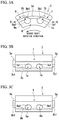
- FIGS. 3A to 3C are enlarged views of the tilting pad 3.
- FIG. 3A is a front view of the tilting pad 3 obtained by viewing the tilting pad 3 in the axial direction of the rotary shaft 300
- FIG. 3B is a side view thereof obtained by viewing the tilting pad 3 in the arrow A direction in FIG. 3A
- FIG. 3C is another side view thereof obtained by viewing the tilting pad 3 in the arrow B direction in FIG. 3A
- the rotation direction of the rotary shaft 300 is a direction from the right side toward the left side of the tilting pad 3 in FIG. 3A (the counterclockwise direction).
- FIGS. 3A to 3C omit an insertion part (an insertion hole) of the tilting pad 3 into which the fixing pin 4 is inserted.
- the tilting pad 3 is a block-shaped member, the shape obtained by viewing the block-shaped member from the front side is an approximate sector shape (a shape obtained by removing from a sector shape, an area including the apex of the sector shape) which curves along the outer circumferential surface of the rotary shaft 300, and the sliding surface of the tilting pad 3 facing the rotary shaft 300 is coated with a white metal.
- the tilting pad 3 has a shape in which a rectangular parallelepiped is bent along the outer circumferential surface of the rotary shaft 300.
- the tilting pad 3 is provided with projections 3a which are disposed on the front and rear sides of the tilting pad 3 and are configured to engage with the side plates 5.
- the tilting pad 3 is provided with an internal flow passageway 6 which allows lubricating oil to flow inside the tilting pad 3.
- the internal flow passageway 6 provided in one tilting pad 3 includes a leading-side internal flow passageway 7 and a trailing-side internal flow passageway 8.
- the leading-side internal flow passageway 7 is provided on the leading side of the tilting pad 3, and the trailing-side internal flow passageway 8 is provided on the trailing side of the tilting pad 3.
- the leading-side internal flow passageway 7 includes two inlet flow passageways 7a which linearly extend in the circumferential direction (a tangential direction) of the rotary shaft 300 and are arranged next to each other in the axial direction of the rotary shaft 300, and a discharge flow passageway 7b which linearly extends and penetrates the tilting pad 3 in the axial direction of the rotary shaft 300 and is connected to each inlet flow passageway 7a.
- the inlet flow passageway 7a includes a leading-side inflow opening 7a1 (first inflow opening) which opens toward the leading side of the tilting pad 3.
- the inlet flow passageway 7a guides into the discharge flow passageway 7b, lubricating oil imported from the leading-side inflow opening 7a1.
- the trailing-side internal flow passageway 8 includes two inlet flow passageways 8a which linearly extend in the circumferential direction (a tangential direction) of the rotary shaft 300 and are arranged next to each other in the axial direction of the rotary shaft 300, and a discharge flow passageway 8b which linearly extends and penetrates the tilting pad 3 in the axial direction of the rotary shaft 300 and is connected to each inlet flow passageway 8a.
- the inlet flow passageway 8a includes a trailing-side inflow opening 8a1 (second inflow opening) which opens toward the trailing side of the tilting pad 3.
- the inlet flow passageway 8a guides into the discharge flow passageway 8b, lubricating oil imported from the trailing-side inflow opening 8a1.
- the internal flow passageway 6 in this embodiment includes the leading-side inflow openings 7a1 which open toward the leading side of the tilting pad 3 in the rotation direction of the rotary shaft 300, the trailing-side inflow openings 8a1 which open toward the trailing side of the tilting pad 3 in the rotation direction of the rotary shaft 300, and the discharge openings 7b1 and the discharge openings 8b1 which open in the axial direction of the rotary shaft 300.
- the internal flow passageway 6 allows lubricating oil to be imported thereinto through the leading-side inflow openings 7a1 and the trailing-side inflow openings 8a1 in the circumferential direction of the rotary shaft 300, and discharges lubricating oil through the discharge openings 7b1 and the discharge openings 8b1 to outside thereof in the axial direction of the rotary shaft 300.
- the tilting pad 3 in this embodiment can be easily manufactured.
- the internal flow passageway 6 includes the leading-side internal flow passageway 7 provided on the leading side of the tilting pad 3, and the trailing-side internal flow passageway 8 provided on the trailing side of the tilting pad 3. Therefore, the tilting pad 3 is provided with no flow passageway passing through the middle part of the tilting pad 3 in the circumferential direction of the rotary shaft 300. Since the fixing pin 4 is inserted into the middle part of the tilting pad 3 (refer to FIG. 2B ), in this embodiment, the internal flow passageway 6 can be formed in an area of the tilting pad 3 other than the middle part. Thus, the internal flow passageway 6 does not require a complicated shape thereof, and can adopt a shape which can be easily formed as described above.
- the fixing pins 4 are screwed into the housing 2, and the end of the fixing pin 4 is inserted into a connection hole provided in the middle part of the tilting pad 3.
- the fixing pin 4 is inserted into the tilting pad 3 so that a slight gap is formed around the end of the fixing pin 4, and restricts large movement (large movement in the circumferential direction or in the axial direction of the housing 2) of the tilting pad 3 while allowing slight tilting (tilting relative to the outer circumferential surface of the rotary shaft 300) of the tilting pad 3.
- the fixing pin 4 is provided in each tilting pad 3.
- the side plate 5 forms the gap S2 which exposes part of the discharge opening 7b1 and part of the discharge opening 8b1 of the tilting pad 3 to outside of the tilting-pad bearing between the side plate 5 and the outer circumferential surface of the rotary shaft 300.
- the gap S2 formed between the side plate 5 and the outer circumferential surface of the rotary shaft 300 exposes at least part of the discharge opening 7b1 and at least part of the discharge opening 8b1 of the tilting pad 3 to outside of the tilting-pad bearing. That is, the gap S2 may expose the entire discharge opening 7b1 and the entire discharge opening 8b1 to outside of the tilting-pad bearing.
- the side plate 5 is divided into two parts 5b and 5c in the vertical direction.
- a gap S3 is provided between the parts 5b and 5c (between the parts disposed next to each other).
- the gap S3 is used for easily discharging to outside of the side plate 5, lubricating oil which has flowed into a space between the tilting pad 3 and the side plate 5, and reduces fluid resistance, thereby making lubricating oil easily flow.
- the side plate 5 has openings 5d, each opening 5d exposing to outside of the tilting-pad bearing, part of the gap S1 formed between the tilting pads 3 disposed next to each other. Similar to the gap S3 described above, the opening 5d is used for easily discharging to outside of the side plate 5, lubricating oil which has flowed into a space between the tilting pad 3 and the side plate 5, and reduces fluid resistance, thereby making lubricating oil easily flow. In addition, the opening 5d may expose the entire gap S1 to outside of the tilting-pad bearing.
- lubricating oil supplied into the gap S1 flows into the internal flow passageways 6 from the leading-side inflow openings 7a1 and from the trailing-side inflow openings 8a1 provided in the tilting pads 3. That is, in this embodiment, lubricating oil flows into the inside of the tilting pad 3 from two sides of the tilting pad 3 in the circumferential direction of the rotary shaft 300.
- lubricating oil which has not flowed into the internal flow passageways 6 is supplied to the outer circumferential surface of the rotary shaft 300 and is guided to the sliding surfaces of the rotary shaft 300 and of the tilting pad 3, or is discharged from the openings 5d to the outside of the side plate 5.
- the lubricating oil which has flowed into the internal flow passageway 6 absorbs heat, thereby cooling the tilting pad 3, and thereafter is discharged to outside of the tilting pad 3 from the discharge openings 7b1 and 8b1 which open so that the opening direction thereof is the same as the axial direction of the rotary shaft 300.
- the lubricating oil discharged from the discharge openings 7b1 and 8b1 is supplied to the outer circumferential surface of the rotary shaft 300, thereafter dropping down in the vertical direction and being collected.
- the gap S2 is formed between the side plate 5 and the outer circumferential surface of the rotary shaft 300, the gap S2 exposing part of the discharge opening 7b1 of and part of the discharge opening 8b1 of the tilting pad 3 to outside of the tilting-pad bearing. Therefore, discharge of the lubricating oil from the discharge openings 7b1 and 8b1 can be smoothly performed, and a large amount of lubricating oil can flow through the internal flow passageway 6, and thus the cooling efficiency of the tilting pad 3 can be further improved.
- the temperature of the trailing side of the tilting pad 3 in the rotation direction of the rotary shaft 300 is higher than that of the leading side thereof.
- the cause thereof may be that flow of the lubricating oil occurs in the rotation direction of the rotary shaft 300 in accordance with the rotation of the rotary shaft 300, and lubricating oil supplied from the lubricating oil-supplying holes 2e is heated due to contact with the tilting pad 3 or the like while moving toward the trailing side of the tilting pad 3, whereby the cooling efficiency of the trailing side of the tilting pad 3 deteriorates.
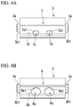
- the opening area of the trailing-side inflow opening 8a1 may be set to be greater than that of the leading-side inflow opening 7a1.
- the amount of lubricating oil flowing into the trailing-side inflow opening 8a1 can become greater than that into the leading-side inflow opening 7a1, and the cooling efficiency of the trailing side of the tilting pad 3 can be further improved compared with that of the leading side thereof.
- the temperature of the entire tilting pad 3 can become constant.
- the flow-passageway diameter of the trailing-side internal flow passageway 8 (the inlet flow passageway 8a and the discharge flow passageway 8b) may be set to be greater than that of the leading-side internal flow passageway 7 (the inlet flow passageway 7a and the discharge flow passageway 7b).
- the above embodiment describes a configuration in which only part of the discharge opening 7b1 and part of the discharge opening 8b1 are exposed at the gap S2 between the side plate 5 and the rotary shaft 300.
- the present invention is not limited thereto, and the entire discharge openings 7b1 and 8b1 may be configured to be exposed at the gap S2.
- the above embodiment describes a configuration in which the side plate 5 is divided into two parts in the vertical direction.
- the present invention is not limited thereto, and the side plate 5 may be divided into three or more parts.
- the above embodiment describes a configuration in which five tilting pads 3 are provided in the tilting-pad bearing.
- the present invention is not limited thereto, and the number of tilting pads can be optionally determined.
- the above embodiment describes a two-stage turbo compressor.
- the present invention is not limited thereto, and an optional number of one or more can be adopted as the number of stages of a turbo compressor.
- the present invention can be used for a tilting-pad bearing and for a turbo compressor using the tilting-pad bearing.
Landscapes
- Engineering & Computer Science (AREA)
- General Engineering & Computer Science (AREA)
- Mechanical Engineering (AREA)
- Chemical & Material Sciences (AREA)
- Oil, Petroleum & Natural Gas (AREA)
- Physics & Mathematics (AREA)
- Fluid Mechanics (AREA)
- Sliding-Contact Bearings (AREA)
- Structures Of Non-Positive Displacement Pumps (AREA)
Description
- The present invention relates to a tilting-pad bearing and a turbo compressor.
- Priority is claimed on Japanese Patent Application No.
2013-160519, filed August 1, 2013 - For example, a rotary shaft of a turbo compressor is rotatably supported by a tilting-pad bearing including tilting pads which are supported by a housing of the bearing so as to be tiltable. Such a tilting-pad bearing is a kind of slide bearing in which a rotary shaft is slidably supported by a plurality of tilting pads arranged annularly around the rotary shaft.
- The tilting pad is heated due to sliding friction during rotation of the rotary shaft. Therefore, for example, in
Patent Documents 1 to 3, the inside of the tilting pad is provided with an internal flow passageway through which lubricating oil flows, the lubricating oil being used for reducing rotation resistance (sliding friction) of the rotary shaft, and cooling for the tilting pad is performed by lubricating oil flowing through the flow passageway. - In addition,
Patent Documents -
- [Patent Document 1] Japanese Unexamined Patent Application, First Publication No.
2003-113834 - [Patent Document 2] Japanese Unexamined Patent Application, First Publication No.
S52-137549 - [Patent Document 3] Japanese Unexamined Patent Application, First Publication No.
2006-112499 - [Patent Document 4] Japanese Unexamined Patent Application, First Publication No.
2010-242842 - [Patent Document 5] Japanese Unexamined Patent Application, First Publication No.
2010-242816 - In recent years, the capacity of a turbo compressor has been increased, and the size of a tilting-pad bearing has also been increased. If the size of the tilting-pad bearing is increased, the size of a tilting pad is also naturally increased. If the size of the tilting pad is increased, since the sliding surface of the tilting pad facing the rotary shaft is expanded or the heat capacity of the tilting pad is increased, further efficient cooling for the tilting pad may be required.
- The present invention has been made in view of the above circumstances, and an object thereof is to improve the cooling efficiency of a tilting pad included in a tilting-pad bearing.
- The present invention adopts the following configurations as means to solve the above problems.
- A first aspect of the present invention is a tilting-pad bearing including: a plurality of tilting pads arranged annularly around a rotary shaft so as to form a gap therebetween; a housing accommodating and supporting the plurality of tilting pads from outside in the radial direction of the rotary shaft and including a lubricating oil-supplying hole provided at a position facing the gap formed between the tilting pads disposed next to each other; and a pair of side plates disposed so that the tilting pads are interposed between the side plates in the axial direction of the rotary shaft. In addition, a tilting pad is provided with an internal flow passageway through which lubricating oil flows, and the internal flow passageway includes: a first inflow opening which opens toward a leading side of the tilting pad in the rotation direction of the rotary shaft; a second inflow opening which opens toward a trailing side of the tilting pad in the rotation direction of the rotary shaft; and a discharge opening which opens in the axial direction of the rotary shaft.
- A second aspect of the present invention is that in the tilting-pad bearing of the first aspect, a gap is formed between a side plate and an outer circumferential surface of the rotary shaft, and exposes at least part of the discharge opening of the tilting pad to outside of the tilting-pad bearing.
- A third aspect of the present invention is that in the tilting-pad bearing of the first or second aspect, a side plate is divided into parts, and a gap is provided between the parts disposed next to each other.
- A fourth aspect of the present invention is that in the tilting-pad bearing of any one of the first to third aspects, a side plate includes an opening which exposes to outside of the tilting-pad bearing, at least part of the gap formed between the tilting pads disposed next to each other.
- A fifth aspect of the present invention is that in the tilting-pad bearing of any one of the first to fourth aspects, the opening area of the second inflow opening is greater than that of the first inflow opening.
- A sixth aspect of the present invention is a turbo compressor including: an impeller; and a rotary shaft connected to the impeller. In addition, the tilting-pad bearing according to any one of
claims 1 to 5 rotatably supports the rotary shaft. - According to the present invention, an internal flow passageway provided in a tilting pad includes: a first inflow opening which opens at a leading side of the tilting pad in the rotation direction of a rotary shaft; and a second inflow opening which opens at a trailing side of the tilting pad in the rotation direction of the rotary shaft. Therefore, in the present invention, lubricating oil flows into the inside of the tilting pad from both of the leading side and the trailing side of the tilting pad in the rotation direction of the rotary shaft. Thus, a large amount of lubricating oil can be imported into the inside of the tilting pad. Furthermore, in the present invention, the lubricating oil which has flowed into the internal flow passageway from the first and second inflow openings is discharged from a discharge opening which opens in the axial direction of the rotary shaft, without flowing backward. Therefore, the lubricating oil can smoothly flow through the internal flow passageway, and the flow velocity of the lubricating oil in the internal flow passageway can be increased. Thus, according to the present invention, since a large amount of lubricating oil smoothly flows through the inside of the tilting pad, the cooling efficiency of the tilting pad can be improved.
-
-
FIG. 1 is a partial cross-sectional view showing part of a turbo compressor including a tilting-pad bearing of an embodiment of the present invention. -
FIG. 2A is a side view of the tilting-pad bearing of the embodiment of the present invention. -
FIG. 2B is a front view of the tilting-pad bearing of the embodiment of the present invention. -
FIG. 3A is a front view of a tilting pad included in the tilting-pad bearing of the embodiment of the present invention. -
FIG. 3B is a side view obtained by viewing the tilting pad in an arrow A direction inFIG. 3A . -
FIG. 3C is a side view obtained by viewing the tilting pad in an arrow B direction inFIG. 3A . -
FIG. 4A is a side view of a tilting pad included in a modification of the tilting-pad bearing of the embodiment of the present invention. -
FIG. 4B is another side view of the tilting pad included in the modification of the tilting-pad bearing of the embodiment of the present invention. - Hereinafter, an embodiment of a tilting-pad bearing and a turbo compressor of the present invention is described with reference to the drawings. In the following drawings, the scale of each member is appropriately changed in order to show each member in a recognizable size.
-
FIG. 1 is a partial cross-sectional view showing part of aturbo compressor 100 including a tilting-pad bearing 1 of this embodiment. Theturbo compressor 100 includes animpeller 200 and arotary shaft 300 whose one end is connected with theimpeller 200 and whose middle part is provided with agear 301, and the tilting-pad bearing 1 of this embodiment rotatably supports therotary shaft 300.FIG. 1 shows two tilting-pad bearings 1 which rotatably support therotary shaft 300. Anair seal 400 and anoil seal 500 are provided between theimpeller 200 and the tilting-pad bearing 1 positioned to be close to theimpeller 200. - The
turbo compressor 100 is a two-stage compressor. The tilting-pad bearing 1, theimpeller 200, theair seal 400 and theoil seal 500 are provided in each of two end portions of therotary shaft 300. However,FIG. 1 shows theimpeller 200, theair seal 400 and theoil seal 500 which are positioned in the right end portion of therotary shaft 300, and omits theimpeller 200, theair seal 400 and theoil seal 500 which are positioned on the left side of therotary shaft 300.FIG. 1 also omits a housing and a driving mechanism, the housing accommodating theimpellers 200 and the like and being provided with flow passageways for air (a fluid to be compressed), the driving mechanism being configured to rotationally drive therotary shaft 300. In addition,FIG. 1 shows a state where a quarter of the tilting-pad bearing 1 in the circumferential direction around therotary shaft 300 is cut out from the tilting-pad bearing 1. That is,FIG. 1 shows a side view of the tilting-pad bearing 1 including a cross-sectional view of part of the tilting-pad bearing 1. - In such a
turbo compressor 100, when the driving mechanism rotationally drives therotary shaft 300, therotary shaft 300 rotates in a state of being supported by the tilting-pad bearings 1, and theimpeller 200 is rotationally driven. Theimpeller 200 is rotationally driven, and thereby air which has been supplied into the housing is compressed and thereafter is discharged to outside of the turbo compressor. - Next, the tilting-
pad bearing 1 of this embodiment is described in detail with reference toFIGS. 2A to 3C . -
FIG. 2A is a side view of the tilting-pad bearing 1 of this embodiment, andFIG. 2B is a front view of the tilting-pad bearing 1 of this embodiment.FIGS. 2A and2B show partial cross-sectional views of the tilting-pad bearing 1 obtained by cutting out part thereof in order to improve the visibility of the internal structure of the tilting-pad bearing 1. - As shown in these drawings, the tilting-
pad bearing 1 of this embodiment includes a housing 2, a plurality oftilting pads 3, a fixingpin 4 provided on eachtilting pad 3, and twoside plates 5. - The housing 2 is an annular member accommodating and supporting the plurality of
tilting pads 3 from outside in the radial direction of therotary shaft 300. As shown inFIG. 2B , the housing 2 includes an upper-side portion 2a and a lower-side portion 2b which are capable of being separated from each other in the vertical direction, apositioning pin 2c which positions the upper-side portion 2a and the lower-side portion 2b, and abolt 2d which fastens the upper-side portion 2a and the lower-side portion 2b. - As shown in
FIG. 2B , the housing 2 is provided with lubricating oil-supplyingholes 2e which penetrate the housing 2 from the outer circumferential surface to the inner circumferential surface thereof. The lubricating oil-supplyingholes 2e guide toward therotary shaft 300, lubricating oil supplied from a pump (not shown) or the like. In this embodiment, in order to supply lubricating oil into all gaps S1, each gap S1 being formed between thetilting pads 3 disposed next to each other, the lubricating oil-supplyingholes 2e are provided so as to correspond to the positions of the gaps S1. That is, the lubricating oil-supplyinghole 2e is provided at a position facing a gap formed between thetilting pads 3 disposed next to each other. In other words, the lubricating oil-supplyinghole 2e and a gap formed between thetilting pads 3 disposed next to each other are arranged in series in the radial direction of therotary shaft 300. In addition, as shown inFIG. 2A , two lubricating oil-supplyingholes 2e are provided so as to face each gap S1, and are arranged in the axial direction of therotary shaft 300. The inner diameter of the lubricating oil-supplyinghole 2e in this embodiment decreases from the outer circumferential surface to the inner circumferential surface of the housing 2. That is, the opening of the lubricating oil-supplyinghole 2e at the outer circumferential surface of the housing 2 is set to be larger than that at the inner circumferential surface of the housing 2. However, the present invention is not limited to this configuration, and the inner diameter of the lubricating oil-supplyinghole 2e may be constant. - The plurality of
tilting pads 3 are arranged annularly around therotary shaft 300 so as to form the gaps S1 therebetween, and slidably support therotary shaft 300. A surface of thetilting pad 3 is coated with, for example, a white metal (a Babbitt metal). As shown inFIG. 2B , in this embodiment, fivetilting pads 3 are disposed at regular intervals in the circumferential direction of therotary shaft 300. -
FIGS. 3A to 3C are enlarged views of thetilting pad 3.FIG. 3A is a front view of thetilting pad 3 obtained by viewing thetilting pad 3 in the axial direction of therotary shaft 300,FIG. 3B is a side view thereof obtained by viewing thetilting pad 3 in the arrow A direction inFIG. 3A, and FIG. 3C is another side view thereof obtained by viewing thetilting pad 3 in the arrow B direction inFIG. 3A . The rotation direction of therotary shaft 300 is a direction from the right side toward the left side of thetilting pad 3 inFIG. 3A (the counterclockwise direction). In addition,FIGS. 3A to 3C omit an insertion part (an insertion hole) of thetilting pad 3 into which thefixing pin 4 is inserted. - For convenience of explanation, a side of the
tilting pad 3 shown inFIG. 3A is called the front side thereof, and another side thereof opposite to the front side is called the rear side thereof. In addition, based on the rotation direction of therotary shaft 300, a side of thetilting pad 3 shown inFIG. 3B is called the leading side thereof, and another side thereof shown inFIG. 3C is called the trailing side thereof. - As shown in these drawings, the
tilting pad 3 is a block-shaped member, the shape obtained by viewing the block-shaped member from the front side is an approximate sector shape (a shape obtained by removing from a sector shape, an area including the apex of the sector shape) which curves along the outer circumferential surface of therotary shaft 300, and the sliding surface of thetilting pad 3 facing therotary shaft 300 is coated with a white metal. In other words, thetilting pad 3 has a shape in which a rectangular parallelepiped is bent along the outer circumferential surface of therotary shaft 300. In addition, thetilting pad 3 is provided withprojections 3a which are disposed on the front and rear sides of thetilting pad 3 and are configured to engage with theside plates 5. - The
tilting pad 3 is provided with aninternal flow passageway 6 which allows lubricating oil to flow inside thetilting pad 3. In this embodiment, theinternal flow passageway 6 provided in onetilting pad 3 includes a leading-sideinternal flow passageway 7 and a trailing-sideinternal flow passageway 8. The leading-sideinternal flow passageway 7 is provided on the leading side of thetilting pad 3, and the trailing-sideinternal flow passageway 8 is provided on the trailing side of thetilting pad 3. - The leading-side
internal flow passageway 7 includes twoinlet flow passageways 7a which linearly extend in the circumferential direction (a tangential direction) of therotary shaft 300 and are arranged next to each other in the axial direction of therotary shaft 300, and adischarge flow passageway 7b which linearly extends and penetrates thetilting pad 3 in the axial direction of therotary shaft 300 and is connected to eachinlet flow passageway 7a. Theinlet flow passageway 7a includes a leading-side inflow opening 7a1 (first inflow opening) which opens toward the leading side of thetilting pad 3. Theinlet flow passageway 7a guides into thedischarge flow passageway 7b, lubricating oil imported from the leading-side inflow opening 7a1. Thedischarge flow passageway 7b includes twodischarge openings 7b which open at two surfaces (front and rear surfaces) of thetilting pad 3 in the axial direction of therotary shaft 300. Thedischarge flow passageway 7b discharges from the discharge openings 7b1 to outside of thetilting pad 3, lubricating oil supplied from theinlet flow passageways 7a. - The trailing-side
internal flow passageway 8 includes twoinlet flow passageways 8a which linearly extend in the circumferential direction (a tangential direction) of therotary shaft 300 and are arranged next to each other in the axial direction of therotary shaft 300, and adischarge flow passageway 8b which linearly extends and penetrates thetilting pad 3 in the axial direction of therotary shaft 300 and is connected to eachinlet flow passageway 8a. Theinlet flow passageway 8a includes a trailing-side inflow opening 8a1 (second inflow opening) which opens toward the trailing side of thetilting pad 3. Theinlet flow passageway 8a guides into thedischarge flow passageway 8b, lubricating oil imported from the trailing-side inflow opening 8a1. Thedischarge flow passageway 8b includes two discharge openings 8b1 which open at two surfaces (front and rear surfaces) of thetilting pad 3 in the axial direction of therotary shaft 300. Thedischarge flow passageway 8b discharges from the discharge openings 8b1 to outside of thetilting pad 3, lubricating oil supplied from theinlet flow passageways 8a. - In this way, the
internal flow passageway 6 in this embodiment includes the leading-side inflow openings 7a1 which open toward the leading side of thetilting pad 3 in the rotation direction of therotary shaft 300, the trailing-side inflow openings 8a1 which open toward the trailing side of thetilting pad 3 in the rotation direction of therotary shaft 300, and the discharge openings 7b1 and the discharge openings 8b1 which open in the axial direction of therotary shaft 300. Theinternal flow passageway 6 allows lubricating oil to be imported thereinto through the leading-side inflow openings 7a1 and the trailing-side inflow openings 8a1 in the circumferential direction of therotary shaft 300, and discharges lubricating oil through the discharge openings 7b1 and the discharge openings 8b1 to outside thereof in the axial direction of therotary shaft 300. - The
internal flow passageway 6, which thetilting pad 3 has, is configured including small flow passageways (theinlet flow passageways 7a, thedischarge flow passageway 7b, theinlet flow passageways 8a, and thedischarge flow passageway 8b) which include openings formed at surfaces of thetilting pad 3 and have a linearly extending shape. Since each small flow passageway has a linearly extending shape, the small flow passageways can be easily formed in thetilting pad 3 using a drill or the like. - Accordingly, the
tilting pad 3 in this embodiment can be easily manufactured. - The
internal flow passageway 6 includes the leading-sideinternal flow passageway 7 provided on the leading side of thetilting pad 3, and the trailing-sideinternal flow passageway 8 provided on the trailing side of thetilting pad 3. Therefore, thetilting pad 3 is provided with no flow passageway passing through the middle part of thetilting pad 3 in the circumferential direction of therotary shaft 300. Since the fixingpin 4 is inserted into the middle part of the tilting pad 3 (refer toFIG. 2B ), in this embodiment, theinternal flow passageway 6 can be formed in an area of thetilting pad 3 other than the middle part. Thus, theinternal flow passageway 6 does not require a complicated shape thereof, and can adopt a shape which can be easily formed as described above. - As shown in
FIG. 2B , the fixing pins 4 are screwed into the housing 2, and the end of the fixingpin 4 is inserted into a connection hole provided in the middle part of thetilting pad 3. The fixingpin 4 is inserted into thetilting pad 3 so that a slight gap is formed around the end of the fixingpin 4, and restricts large movement (large movement in the circumferential direction or in the axial direction of the housing 2) of thetilting pad 3 while allowing slight tilting (tilting relative to the outer circumferential surface of the rotary shaft 300) of thetilting pad 3. The fixingpin 4 is provided in eachtilting pad 3. - As shown in
FIG. 2A , twoside plates 5 are disposed so that thetilting pads 3 are interposed between theside plates 5 in the axial direction of therotary shaft 300. The inner wall surface (the surface facing the tilting pad 3) of eachside plate 5 is provided with arecess 5a, and theside plate 5 is fixed to the housing 2 so that theprojection 3a of thetilting pad 3 is engaged with therecess 5a. In addition, a slight gap is formed between eachside plate 5 and eachtilting pad 3 in order not to disturb tilting of thetilting pad 3. - As shown in
FIG. 2B , theside plate 5 has an annular shape encircling therotary shaft 300. The width (the length from the inner circumferential part of theside plate 5 facing therotary shaft 300 to the outer circumferential part thereof) of theside plate 5 in the radial direction of therotary shaft 300 is set so that a gap S2 is formed between theside plate 5 and the outer circumferential surface of therotary shaft 300, the gap S2 exposing part of the discharge opening 7b1 and part of the discharge opening 8b1 of thetilting pad 3 to outside of the tilting-pad bearing. That is, in this embodiment, theside plate 5 forms the gap S2 which exposes part of the discharge opening 7b1 and part of the discharge opening 8b1 of thetilting pad 3 to outside of the tilting-pad bearing between theside plate 5 and the outer circumferential surface of therotary shaft 300. In other words, the gap S2 formed between theside plate 5 and the outer circumferential surface of therotary shaft 300 exposes at least part of the discharge opening 7b1 and at least part of the discharge opening 8b1 of thetilting pad 3 to outside of the tilting-pad bearing. That is, the gap S2 may expose the entire discharge opening 7b1 and the entire discharge opening 8b1 to outside of the tilting-pad bearing. - As shown in
FIG. 2B , theside plate 5 is divided into twoparts parts side plate 5, lubricating oil which has flowed into a space between thetilting pad 3 and theside plate 5, and reduces fluid resistance, thereby making lubricating oil easily flow. - As shown in
FIG. 2B , theside plate 5 hasopenings 5d, eachopening 5d exposing to outside of the tilting-pad bearing, part of the gap S1 formed between thetilting pads 3 disposed next to each other. Similar to the gap S3 described above, theopening 5d is used for easily discharging to outside of theside plate 5, lubricating oil which has flowed into a space between thetilting pad 3 and theside plate 5, and reduces fluid resistance, thereby making lubricating oil easily flow. In addition, theopening 5d may expose the entire gap S1 to outside of the tilting-pad bearing. - In the tilting-
pad bearing 1 of this embodiment having the above configurations, when lubricating oil is supplied from outside of the tilting-pad bearing into the lubricating oil-supplyinghole 2e provided in the housing 2, the lubricating oil is supplied into the gap S1 formed between thetilting pads 3 disposed next to each other. - Part of the lubricating oil supplied into the gap S1 flows into the
internal flow passageways 6 from the leading-side inflow openings 7a1 and from the trailing-side inflow openings 8a1 provided in thetilting pads 3. That is, in this embodiment, lubricating oil flows into the inside of thetilting pad 3 from two sides of thetilting pad 3 in the circumferential direction of therotary shaft 300. In addition, lubricating oil which has not flowed into theinternal flow passageways 6 is supplied to the outer circumferential surface of therotary shaft 300 and is guided to the sliding surfaces of therotary shaft 300 and of thetilting pad 3, or is discharged from theopenings 5d to the outside of theside plate 5. - The lubricating oil which has flowed into the
internal flow passageway 6 absorbs heat, thereby cooling thetilting pad 3, and thereafter is discharged to outside of thetilting pad 3 from the discharge openings 7b1 and 8b1 which open so that the opening direction thereof is the same as the axial direction of therotary shaft 300. The lubricating oil discharged from the discharge openings 7b1 and 8b1 is supplied to the outer circumferential surface of therotary shaft 300, thereafter dropping down in the vertical direction and being collected. - In the tilting-
pad bearing 1 of this embodiment as described above, theinternal flow passageway 6 provided in thetilting pad 3 includes the leading-side inflow openings 7a1 which open at the leading side of thetilting pad 3 in the rotation direction of therotary shaft 300, and the trailing-side inflow openings 8a1 which open at the trailing side of thetilting pad 3 in the rotation direction of therotary shaft 300. Therefore, in the tilting-pad bearing 1 of this embodiment, lubricating oil flows into the inside of thetilting pad 3 from both of the leading side and the trailing side thereof in the rotation direction of therotary shaft 300. Thus, a large amount of lubricating oil can be imported into the inside of thetilting pad 3. Furthermore, in the tilting-pad bearing 1 of this embodiment, the lubricating oil, which has flowed into theinternal flow passageway 6 from the leading-side inflow openings 7a1 and from the trailing-side inflow openings 8a1, is discharged from the discharge openings 7b1 and 8b1 which open in the axial direction of the rotary shaft, without flowing backward. Therefore, it is possible to make the lubricating oil smoothly flow through theinternal flow passageway 6, and to increase the flow velocity of the lubricating oil in theinternal flow passageway 6. Thus, according to the tilting-pad bearing 1 of this embodiment, since a large amount of lubricating oil smoothly flows through the inside of thetilting pad 3, the cooling efficiency of thetilting pad 3 can be improved. - In the tilting-
pad bearing 1 of this embodiment, the gap S2 is formed between theside plate 5 and the outer circumferential surface of therotary shaft 300, the gap S2 exposing part of the discharge opening 7b1 of and part of the discharge opening 8b1 of thetilting pad 3 to outside of the tilting-pad bearing. Therefore, discharge of the lubricating oil from the discharge openings 7b1 and 8b1 can be smoothly performed, and a large amount of lubricating oil can flow through theinternal flow passageway 6, and thus the cooling efficiency of thetilting pad 3 can be further improved. - In the tilting-
pad bearing 1 of this embodiment, theside plate 5 is divided into two parts (theparts pad bearing 1 of this embodiment, theside plate 5 has theopenings 5d which expose to outside of the tilting-pad bearing, the gaps S1 formed between thetilting pads 3 disposed next to each other. - Therefore, discharge of the lubricating oil to outside of the
side plate 5 can be facilitated, thereby reducing fluid resistance, and a further large amount of lubricating oil can easily flow into the inside of the tilting-pad bearing 1. Thus, the cooling efficiency of thetilting pad 3 or the like can be further improved. - Hereinbefore, although the embodiment of the present invention has been described with reference to the attached drawings, the present invention is not limited to the above embodiment. The shape, the combination or the like of each component shown in the above embodiment is an example, and various modifications based on design requests or the like can be adopted within the scope of and not departing from the present invention.
- For example, the temperature of the trailing side of the
tilting pad 3 in the rotation direction of therotary shaft 300 is higher than that of the leading side thereof. The cause thereof may be that flow of the lubricating oil occurs in the rotation direction of therotary shaft 300 in accordance with the rotation of therotary shaft 300, and lubricating oil supplied from the lubricating oil-supplyingholes 2e is heated due to contact with thetilting pad 3 or the like while moving toward the trailing side of thetilting pad 3, whereby the cooling efficiency of the trailing side of thetilting pad 3 deteriorates. Accordingly, for example, as shown inFIGS. 4A and 4B , the opening area of the trailing-side inflow opening 8a1 may be set to be greater than that of the leading-side inflow opening 7a1. - If this configuration is adopted, the amount of lubricating oil flowing into the trailing-side inflow opening 8a1 can become greater than that into the leading-side inflow opening 7a1, and the cooling efficiency of the trailing side of the
tilting pad 3 can be further improved compared with that of the leading side thereof. Thus, the temperature of theentire tilting pad 3 can become constant. In addition, the flow-passageway diameter of the trailing-side internal flow passageway 8 (theinlet flow passageway 8a and thedischarge flow passageway 8b) may be set to be greater than that of the leading-side internal flow passageway 7 (theinlet flow passageway 7a and thedischarge flow passageway 7b). - The above embodiment describes a configuration in which only part of the discharge opening 7b1 and part of the discharge opening 8b1 are exposed at the gap S2 between the
side plate 5 and therotary shaft 300. - However, the present invention is not limited thereto, and the entire discharge openings 7b1 and 8b1 may be configured to be exposed at the gap S2.
- The above embodiment describes a configuration in which the
side plate 5 is divided into two parts in the vertical direction. However, the present invention is not limited thereto, and theside plate 5 may be divided into three or more parts. - The above embodiment describes a configuration in which five
tilting pads 3 are provided in the tilting-pad bearing. However, the present invention is not limited thereto, and the number of tilting pads can be optionally determined. - The above embodiment describes a two-stage turbo compressor. However, the present invention is not limited thereto, and an optional number of one or more can be adopted as the number of stages of a turbo compressor.
- The present invention can be used for a tilting-pad bearing and for a turbo compressor using the tilting-pad bearing.
-
- 1
- tilting-pad bearing
- 2
- housing
- 2a
- upper-side portion
- 2b
- lower-side portion
- 2c
- pin
- 2d
- bolt
- 2e
- lubricating oil-supplying hole
- 3
- tilting pad
- 3a
- projection
- 4
- fixing pin
- 5
- side plate
- 5a
- recess
- 5b
- part
- 5c
- part
- 5d
- opening
- 6
- internal flow passageway
- 7
- leading-side internal flow passageway
- 7a
- inlet flow passageway
- 7a1
- leading-side inflow opening (first inflow opening)
- 7b
- discharge flow passageway
- 7b1
- discharge opening
- 8
- trailing-side internal flow passageway
- 8a
- inlet flow passageway
- 8a1
- trailing-side inflow opening (second inflow opening)
- 8b
- discharge flow passageway
- 8b1
- discharge opening
- 100
- turbo compressor
- 200
- impeller
- 300
- rotary shaft
- 301
- gear
- 400
- air seal
- 500
- oil seal
- S1
- gap
- S2
- gap
- S3
- gap
Claims (6)
- A tilting-pad bearing, comprising:a plurality of tilting pads arranged annularly around a rotary shaft so as to form a gap therebetween;a housing accommodating and supporting the plurality of tilting pads from outside in a radial direction of the rotary shaft and including a lubricating oil-supplying hole provided at a position facing the gap formed between the tilting pads disposed next to each other; anda pair of side plates disposed so that the tilting pads are interposed between the side plates in an axial direction of the rotary shaft,wherein a tilting pad is provided with an internal flow passageway through which lubricating oil flows, andthe internal flow passageway includes:a first inflow opening which opens toward a leading side of the tilting pad in a rotation direction of the rotary shaft,a second inflow opening which opens toward a trailing side of the tilting pad in the rotation direction of the rotary shaft, anda discharge opening which opens in the axial direction of the rotary shaft.
- The tilting-pad bearing according to claim 1,
wherein a gap is formed between a side plate and an outer circumferential surface of the rotary shaft, and exposes at least part of the discharge opening of the tilting pad to outside of the tilting-pad bearing. - The tilting-pad bearing according to claim 1 or 2,
wherein a side plate is divided into parts, and a gap is provided between the parts disposed next to each other. - The tilting-pad bearing according to any one of claims 1 to 3,
wherein a side plate includes an opening which exposes to outside of the tilting-pad bearing, at least part of the gap formed between the tilting pads disposed next to each other. - The tilting-pad bearing according to any one of claims 1 to 4,
wherein the opening area of the second inflow opening is greater than that of the first inflow opening. - A turbo compressor, comprising:an impeller; anda rotary shaft connected to the impeller,wherein the tilting-pad bearing according to any one of claims 1 to 5 rotatably supports the rotary shaft.
Applications Claiming Priority (2)
| Application Number | Priority Date | Filing Date | Title |
|---|---|---|---|
| JP2013160519A JP6410006B2 (en) | 2013-08-01 | 2013-08-01 | Tilting pad bearing and turbo compressor |
| PCT/JP2014/068493 WO2015016035A1 (en) | 2013-08-01 | 2014-07-10 | Tilting pad bearing and turbo compressor |
Publications (3)
| Publication Number | Publication Date |
|---|---|
| EP3029343A1 true EP3029343A1 (en) | 2016-06-08 |
| EP3029343A4 EP3029343A4 (en) | 2017-03-01 |
| EP3029343B1 EP3029343B1 (en) | 2018-09-05 |
Family
ID=52431575
Family Applications (1)
| Application Number | Title | Priority Date | Filing Date |
|---|---|---|---|
| EP14832859.4A Active EP3029343B1 (en) | 2013-08-01 | 2014-07-10 | Tilting pad bearing and turbo compressor |
Country Status (6)
| Country | Link |
|---|---|
| US (1) | US10247239B2 (en) |
| EP (1) | EP3029343B1 (en) |
| JP (1) | JP6410006B2 (en) |
| KR (1) | KR101911818B1 (en) |
| CN (1) | CN105378306B (en) |
| WO (1) | WO2015016035A1 (en) |
Families Citing this family (6)
| Publication number | Priority date | Publication date | Assignee | Title |
|---|---|---|---|---|
| US10077802B2 (en) * | 2014-10-23 | 2018-09-18 | Borgwarner, Inc. | Tilting pad journal bearing assembly |
| EP3250834B1 (en) * | 2015-01-30 | 2021-01-20 | Siemens Aktiengesellschaft | Bearing shoe for supporting a rotor journal in a turbine engine |
| JP2017096301A (en) * | 2015-11-18 | 2017-06-01 | 三菱重工業株式会社 | Bearing device and rotary machine |
| JP6571026B2 (en) | 2016-02-29 | 2019-09-04 | 三菱日立パワーシステムズ株式会社 | Journal bearing and rotating machine |
| DE102016216396A1 (en) * | 2016-08-31 | 2018-03-01 | Robert Bosch Gmbh | tilting pad |
| JP7468639B2 (en) * | 2020-05-21 | 2024-04-16 | 株式会社Ihi | Bearings and turbochargers |
Family Cites Families (20)
| Publication number | Priority date | Publication date | Assignee | Title |
|---|---|---|---|---|
| JPS5155846A (en) * | 1974-11-11 | 1976-05-17 | Hitachi Ltd | SUIRYOKUJIKUKE SOCHI |
| JPS52137549A (en) | 1976-05-12 | 1977-11-17 | Mitsubishi Heavy Ind Ltd | Inclined-moving pad type journal bearing |
| JPS5348149A (en) * | 1976-10-13 | 1978-05-01 | Hitachi Ltd | Tilting pad bearing |
| JPS5830523A (en) * | 1981-08-18 | 1983-02-23 | Ebara Corp | Inclined pad type vibration suppressing bearing |
| CH672666A5 (en) * | 1986-11-27 | 1989-12-15 | Bbc Brown Boveri & Cie | |
| US5007745A (en) * | 1989-09-26 | 1991-04-16 | Delaware Capital Formation, Inc. | Low flow tilting pad thrust bearing |
| JP2001200847A (en) * | 1999-11-08 | 2001-07-27 | Mitsubishi Heavy Ind Ltd | Bearing device and turbine |
| US6739756B2 (en) * | 2001-03-12 | 2004-05-25 | Whm Holding Corporation | Combination thrust bearing and journal bearing, and method for distributing fluid to same |
| JP4722340B2 (en) * | 2001-08-08 | 2011-07-13 | Thk株式会社 | Dynamic pressure sealing device and rotary joint device using the same |
| JP2003113834A (en) * | 2001-10-09 | 2003-04-18 | Mitsubishi Heavy Ind Ltd | Tilting pad type bearing |
| JP2006112499A (en) * | 2004-10-14 | 2006-04-27 | Mitsubishi Heavy Ind Ltd | Tilting pad bearing |
| JP4675643B2 (en) * | 2005-02-28 | 2011-04-27 | 株式会社東芝 | Journal bearing |
| CN1776241A (en) * | 2005-12-15 | 2006-05-24 | 上海交通大学 | Integral multi-oil wedge tilting pad dynamic pressure sliding bearing |
| NO336347B1 (en) | 2007-03-02 | 2015-08-03 | Framo Eng As | Device at resilient bearing for supporting a pivot tower on board a vessel |
| CN101216065A (en) * | 2007-12-29 | 2008-07-09 | 东方电气集团东方汽轮机有限公司 | Annular oil passage type tilting pad bearing |
| JP2010242816A (en) * | 2009-04-02 | 2010-10-28 | Ihi Corp | Tilting pad bearing |
| JP5169954B2 (en) * | 2009-04-03 | 2013-03-27 | 株式会社Ihi | Tilting pad bearing |
| JP2010249200A (en) * | 2009-04-14 | 2010-11-04 | Ihi Corp | Tilting pad bearing and rotary machine |
| WO2013043495A1 (en) * | 2011-09-21 | 2013-03-28 | Dresser-Rand Company | Tilt pad bearing with through-pivot lubrication |
| KR102232710B1 (en) * | 2013-03-13 | 2021-03-30 | 워케샤 베어링즈 코퍼레이션 | Trailing edge cooled bearing |
-
2013
- 2013-08-01 JP JP2013160519A patent/JP6410006B2/en active Active
-
2014
- 2014-07-10 EP EP14832859.4A patent/EP3029343B1/en active Active
- 2014-07-10 WO PCT/JP2014/068493 patent/WO2015016035A1/en not_active Ceased
- 2014-07-10 KR KR1020167003528A patent/KR101911818B1/en active Active
- 2014-07-10 CN CN201480039900.5A patent/CN105378306B/en active Active
-
2016
- 2016-01-13 US US14/994,182 patent/US10247239B2/en not_active Expired - Fee Related
Non-Patent Citations (1)
| Title |
|---|
| See references of WO2015016035A1 * |
Also Published As
| Publication number | Publication date |
|---|---|
| JP6410006B2 (en) | 2018-10-24 |
| US10247239B2 (en) | 2019-04-02 |
| WO2015016035A1 (en) | 2015-02-05 |
| CN105378306B (en) | 2017-11-14 |
| EP3029343A4 (en) | 2017-03-01 |
| JP2015031331A (en) | 2015-02-16 |
| CN105378306A (en) | 2016-03-02 |
| EP3029343B1 (en) | 2018-09-05 |
| KR101911818B1 (en) | 2018-10-25 |
| US20160123391A1 (en) | 2016-05-05 |
| KR20160028482A (en) | 2016-03-11 |
Similar Documents
| Publication | Publication Date | Title |
|---|---|---|
| US10247239B2 (en) | Tilting-pad bearing and turbo compressor | |
| JP5416859B2 (en) | Tilting pad type journal bearing and rotating machine having the same | |
| CN109882284B (en) | Turbocharger | |
| JP5735715B2 (en) | Mechanical seal assembly with Tesla pump | |
| CN108930651B (en) | Pump body assembly and compressor | |
| JP2006038221A (en) | Thrust bearing | |
| JP2008309123A (en) | Centrifugal compressor casing | |
| US10858952B2 (en) | Variable displacement turbocharger | |
| JP6405590B2 (en) | Compressor | |
| CN107850114B (en) | Multi-arc bearing and supercharger | |
| CN108691770B (en) | Screw compressor | |
| US20190331116A1 (en) | Method for cooling a compressor or vacuum pump and a compressor or vacuum pump applying such a method | |
| JP2009127437A (en) | Supercharger | |
| JP2017082908A (en) | Thrust foil bearing | |
| JP2004263690A (en) | Vane type vacuum pump | |
| CN108026771B (en) | Method for cooling a compressor or vacuum pump and compressor or vacuum pump applying the method | |
| WO2019077962A1 (en) | Seal structure for supercharger | |
| WO2015098896A1 (en) | Bearing device and pump | |
| JP2006083852A (en) | Low input torque rotor for vane pump | |
| JP2017009043A (en) | Bearing device and pump | |
| JP5169954B2 (en) | Tilting pad bearing | |
| CN114810810A (en) | Dynamic pressure thrust bearing | |
| CN103384765B (en) | Rotating system for a wind turbine | |
| JP2005273478A (en) | Vane rotary vacuum pump | |
| JP6106557B2 (en) | Double suction centrifugal pump |
Legal Events
| Date | Code | Title | Description |
|---|---|---|---|
| PUAI | Public reference made under article 153(3) epc to a published international application that has entered the european phase |
Free format text: ORIGINAL CODE: 0009012 |
|
| 17P | Request for examination filed |
Effective date: 20160118 |
|
| AK | Designated contracting states |
Kind code of ref document: A1 Designated state(s): AL AT BE BG CH CY CZ DE DK EE ES FI FR GB GR HR HU IE IS IT LI LT LU LV MC MK MT NL NO PL PT RO RS SE SI SK SM TR |
|
| AX | Request for extension of the european patent |
Extension state: BA ME |
|
| DAX | Request for extension of the european patent (deleted) | ||
| A4 | Supplementary search report drawn up and despatched |
Effective date: 20170131 |
|
| RIC1 | Information provided on ipc code assigned before grant |
Ipc: F04D 29/046 20060101ALI20170125BHEP Ipc: F16C 17/03 20060101AFI20170125BHEP Ipc: F16C 33/10 20060101ALI20170125BHEP |
|
| GRAP | Despatch of communication of intention to grant a patent |
Free format text: ORIGINAL CODE: EPIDOSNIGR1 |
|
| STAA | Information on the status of an ep patent application or granted ep patent |
Free format text: STATUS: GRANT OF PATENT IS INTENDED |
|
| INTG | Intention to grant announced |
Effective date: 20180418 |
|
| RAP1 | Party data changed (applicant data changed or rights of an application transferred) |
Owner name: IHI ROTATING MACHINERY ENGINEERING CO. LTD. |
|
| GRAS | Grant fee paid |
Free format text: ORIGINAL CODE: EPIDOSNIGR3 |
|
| GRAA | (expected) grant |
Free format text: ORIGINAL CODE: 0009210 |
|
| STAA | Information on the status of an ep patent application or granted ep patent |
Free format text: STATUS: THE PATENT HAS BEEN GRANTED |
|
| AK | Designated contracting states |
Kind code of ref document: B1 Designated state(s): AL AT BE BG CH CY CZ DE DK EE ES FI FR GB GR HR HU IE IS IT LI LT LU LV MC MK MT NL NO PL PT RO RS SE SI SK SM TR |
|
| REG | Reference to a national code |
Ref country code: GB Ref legal event code: FG4D |
|
| REG | Reference to a national code |
Ref country code: CH Ref legal event code: EP |
|
| REG | Reference to a national code |
Ref country code: AT Ref legal event code: REF Ref document number: 1038162 Country of ref document: AT Kind code of ref document: T Effective date: 20180915 |
|
| REG | Reference to a national code |
Ref country code: IE Ref legal event code: FG4D |
|
| REG | Reference to a national code |
Ref country code: DE Ref legal event code: R096 Ref document number: 602014032006 Country of ref document: DE |
|
| REG | Reference to a national code |
Ref country code: NL Ref legal event code: MP Effective date: 20180905 |
|
| REG | Reference to a national code |
Ref country code: LT Ref legal event code: MG4D |
|
| PG25 | Lapsed in a contracting state [announced via postgrant information from national office to epo] |
Ref country code: FI Free format text: LAPSE BECAUSE OF FAILURE TO SUBMIT A TRANSLATION OF THE DESCRIPTION OR TO PAY THE FEE WITHIN THE PRESCRIBED TIME-LIMIT Effective date: 20180905 Ref country code: LT Free format text: LAPSE BECAUSE OF FAILURE TO SUBMIT A TRANSLATION OF THE DESCRIPTION OR TO PAY THE FEE WITHIN THE PRESCRIBED TIME-LIMIT Effective date: 20180905 Ref country code: NO Free format text: LAPSE BECAUSE OF FAILURE TO SUBMIT A TRANSLATION OF THE DESCRIPTION OR TO PAY THE FEE WITHIN THE PRESCRIBED TIME-LIMIT Effective date: 20181205 Ref country code: BG Free format text: LAPSE BECAUSE OF FAILURE TO SUBMIT A TRANSLATION OF THE DESCRIPTION OR TO PAY THE FEE WITHIN THE PRESCRIBED TIME-LIMIT Effective date: 20181205 Ref country code: SE Free format text: LAPSE BECAUSE OF FAILURE TO SUBMIT A TRANSLATION OF THE DESCRIPTION OR TO PAY THE FEE WITHIN THE PRESCRIBED TIME-LIMIT Effective date: 20180905 Ref country code: GR Free format text: LAPSE BECAUSE OF FAILURE TO SUBMIT A TRANSLATION OF THE DESCRIPTION OR TO PAY THE FEE WITHIN THE PRESCRIBED TIME-LIMIT Effective date: 20181206 Ref country code: RS Free format text: LAPSE BECAUSE OF FAILURE TO SUBMIT A TRANSLATION OF THE DESCRIPTION OR TO PAY THE FEE WITHIN THE PRESCRIBED TIME-LIMIT Effective date: 20180905 |
|
| REG | Reference to a national code |
Ref country code: AT Ref legal event code: MK05 Ref document number: 1038162 Country of ref document: AT Kind code of ref document: T Effective date: 20180905 |
|
| PG25 | Lapsed in a contracting state [announced via postgrant information from national office to epo] |
Ref country code: HR Free format text: LAPSE BECAUSE OF FAILURE TO SUBMIT A TRANSLATION OF THE DESCRIPTION OR TO PAY THE FEE WITHIN THE PRESCRIBED TIME-LIMIT Effective date: 20180905 Ref country code: LV Free format text: LAPSE BECAUSE OF FAILURE TO SUBMIT A TRANSLATION OF THE DESCRIPTION OR TO PAY THE FEE WITHIN THE PRESCRIBED TIME-LIMIT Effective date: 20180905 Ref country code: AL Free format text: LAPSE BECAUSE OF FAILURE TO SUBMIT A TRANSLATION OF THE DESCRIPTION OR TO PAY THE FEE WITHIN THE PRESCRIBED TIME-LIMIT Effective date: 20180905 |
|
| PG25 | Lapsed in a contracting state [announced via postgrant information from national office to epo] |
Ref country code: CZ Free format text: LAPSE BECAUSE OF FAILURE TO SUBMIT A TRANSLATION OF THE DESCRIPTION OR TO PAY THE FEE WITHIN THE PRESCRIBED TIME-LIMIT Effective date: 20180905 Ref country code: IT Free format text: LAPSE BECAUSE OF FAILURE TO SUBMIT A TRANSLATION OF THE DESCRIPTION OR TO PAY THE FEE WITHIN THE PRESCRIBED TIME-LIMIT Effective date: 20180905 Ref country code: AT Free format text: LAPSE BECAUSE OF FAILURE TO SUBMIT A TRANSLATION OF THE DESCRIPTION OR TO PAY THE FEE WITHIN THE PRESCRIBED TIME-LIMIT Effective date: 20180905 Ref country code: EE Free format text: LAPSE BECAUSE OF FAILURE TO SUBMIT A TRANSLATION OF THE DESCRIPTION OR TO PAY THE FEE WITHIN THE PRESCRIBED TIME-LIMIT Effective date: 20180905 Ref country code: RO Free format text: LAPSE BECAUSE OF FAILURE TO SUBMIT A TRANSLATION OF THE DESCRIPTION OR TO PAY THE FEE WITHIN THE PRESCRIBED TIME-LIMIT Effective date: 20180905 Ref country code: IS Free format text: LAPSE BECAUSE OF FAILURE TO SUBMIT A TRANSLATION OF THE DESCRIPTION OR TO PAY THE FEE WITHIN THE PRESCRIBED TIME-LIMIT Effective date: 20190105 Ref country code: NL Free format text: LAPSE BECAUSE OF FAILURE TO SUBMIT A TRANSLATION OF THE DESCRIPTION OR TO PAY THE FEE WITHIN THE PRESCRIBED TIME-LIMIT Effective date: 20180905 Ref country code: ES Free format text: LAPSE BECAUSE OF FAILURE TO SUBMIT A TRANSLATION OF THE DESCRIPTION OR TO PAY THE FEE WITHIN THE PRESCRIBED TIME-LIMIT Effective date: 20180905 Ref country code: PL Free format text: LAPSE BECAUSE OF FAILURE TO SUBMIT A TRANSLATION OF THE DESCRIPTION OR TO PAY THE FEE WITHIN THE PRESCRIBED TIME-LIMIT Effective date: 20180905 |
|
| PG25 | Lapsed in a contracting state [announced via postgrant information from national office to epo] |
Ref country code: PT Free format text: LAPSE BECAUSE OF FAILURE TO SUBMIT A TRANSLATION OF THE DESCRIPTION OR TO PAY THE FEE WITHIN THE PRESCRIBED TIME-LIMIT Effective date: 20190105 Ref country code: SK Free format text: LAPSE BECAUSE OF FAILURE TO SUBMIT A TRANSLATION OF THE DESCRIPTION OR TO PAY THE FEE WITHIN THE PRESCRIBED TIME-LIMIT Effective date: 20180905 Ref country code: SM Free format text: LAPSE BECAUSE OF FAILURE TO SUBMIT A TRANSLATION OF THE DESCRIPTION OR TO PAY THE FEE WITHIN THE PRESCRIBED TIME-LIMIT Effective date: 20180905 |
|
| REG | Reference to a national code |
Ref country code: DE Ref legal event code: R097 Ref document number: 602014032006 Country of ref document: DE |
|
| PLBE | No opposition filed within time limit |
Free format text: ORIGINAL CODE: 0009261 |
|
| STAA | Information on the status of an ep patent application or granted ep patent |
Free format text: STATUS: NO OPPOSITION FILED WITHIN TIME LIMIT |
|
| PG25 | Lapsed in a contracting state [announced via postgrant information from national office to epo] |
Ref country code: DK Free format text: LAPSE BECAUSE OF FAILURE TO SUBMIT A TRANSLATION OF THE DESCRIPTION OR TO PAY THE FEE WITHIN THE PRESCRIBED TIME-LIMIT Effective date: 20180905 |
|
| 26N | No opposition filed |
Effective date: 20190606 |
|
| PG25 | Lapsed in a contracting state [announced via postgrant information from national office to epo] |
Ref country code: SI Free format text: LAPSE BECAUSE OF FAILURE TO SUBMIT A TRANSLATION OF THE DESCRIPTION OR TO PAY THE FEE WITHIN THE PRESCRIBED TIME-LIMIT Effective date: 20180905 |
|
| PG25 | Lapsed in a contracting state [announced via postgrant information from national office to epo] |
Ref country code: MC Free format text: LAPSE BECAUSE OF FAILURE TO SUBMIT A TRANSLATION OF THE DESCRIPTION OR TO PAY THE FEE WITHIN THE PRESCRIBED TIME-LIMIT Effective date: 20180905 |
|
| REG | Reference to a national code |
Ref country code: CH Ref legal event code: PL |
|
| GBPC | Gb: european patent ceased through non-payment of renewal fee |
Effective date: 20190710 |
|
| PG25 | Lapsed in a contracting state [announced via postgrant information from national office to epo] |
Ref country code: GB Free format text: LAPSE BECAUSE OF NON-PAYMENT OF DUE FEES Effective date: 20190710 |
|
| PG25 | Lapsed in a contracting state [announced via postgrant information from national office to epo] |
Ref country code: LI Free format text: LAPSE BECAUSE OF NON-PAYMENT OF DUE FEES Effective date: 20190731 Ref country code: CH Free format text: LAPSE BECAUSE OF NON-PAYMENT OF DUE FEES Effective date: 20190731 Ref country code: LU Free format text: LAPSE BECAUSE OF NON-PAYMENT OF DUE FEES Effective date: 20190710 |
|
| PG25 | Lapsed in a contracting state [announced via postgrant information from national office to epo] |
Ref country code: FR Free format text: LAPSE BECAUSE OF NON-PAYMENT OF DUE FEES Effective date: 20190731 |
|
| PG25 | Lapsed in a contracting state [announced via postgrant information from national office to epo] |
Ref country code: IE Free format text: LAPSE BECAUSE OF NON-PAYMENT OF DUE FEES Effective date: 20190710 |
|
| PG25 | Lapsed in a contracting state [announced via postgrant information from national office to epo] |
Ref country code: CY Free format text: LAPSE BECAUSE OF FAILURE TO SUBMIT A TRANSLATION OF THE DESCRIPTION OR TO PAY THE FEE WITHIN THE PRESCRIBED TIME-LIMIT Effective date: 20180905 |
|
| PG25 | Lapsed in a contracting state [announced via postgrant information from national office to epo] |
Ref country code: MT Free format text: LAPSE BECAUSE OF FAILURE TO SUBMIT A TRANSLATION OF THE DESCRIPTION OR TO PAY THE FEE WITHIN THE PRESCRIBED TIME-LIMIT Effective date: 20180905 Ref country code: HU Free format text: LAPSE BECAUSE OF FAILURE TO SUBMIT A TRANSLATION OF THE DESCRIPTION OR TO PAY THE FEE WITHIN THE PRESCRIBED TIME-LIMIT; INVALID AB INITIO Effective date: 20140710 |
|
| PG25 | Lapsed in a contracting state [announced via postgrant information from national office to epo] |
Ref country code: MK Free format text: LAPSE BECAUSE OF FAILURE TO SUBMIT A TRANSLATION OF THE DESCRIPTION OR TO PAY THE FEE WITHIN THE PRESCRIBED TIME-LIMIT Effective date: 20180905 |
|
| PGFP | Annual fee paid to national office [announced via postgrant information from national office to epo] |
Ref country code: BE Payment date: 20250619 Year of fee payment: 12 |
|
| PGFP | Annual fee paid to national office [announced via postgrant information from national office to epo] |
Ref country code: DE Payment date: 20250528 Year of fee payment: 12 |
|
| PGFP | Annual fee paid to national office [announced via postgrant information from national office to epo] |
Ref country code: TR Payment date: 20250703 Year of fee payment: 12 |