EP3028911A1 - Linkage assembly for coupling a plunger of an actuator to a manually operated input member - Google Patents
Linkage assembly for coupling a plunger of an actuator to a manually operated input member Download PDFInfo
- Publication number
- EP3028911A1 EP3028911A1 EP15188052.3A EP15188052A EP3028911A1 EP 3028911 A1 EP3028911 A1 EP 3028911A1 EP 15188052 A EP15188052 A EP 15188052A EP 3028911 A1 EP3028911 A1 EP 3028911A1
- Authority
- EP
- European Patent Office
- Prior art keywords
- pushrod
- linkage assembly
- plunger
- resilient member
- assembly according
- Prior art date
- Legal status (The legal status is an assumption and is not a legal conclusion. Google has not performed a legal analysis and makes no representation as to the accuracy of the status listed.)
- Granted
Links
Images




Classifications
-
- B—PERFORMING OPERATIONS; TRANSPORTING
- B60—VEHICLES IN GENERAL
- B60T—VEHICLE BRAKE CONTROL SYSTEMS OR PARTS THEREOF; BRAKE CONTROL SYSTEMS OR PARTS THEREOF, IN GENERAL; ARRANGEMENT OF BRAKING ELEMENTS ON VEHICLES IN GENERAL; PORTABLE DEVICES FOR PREVENTING UNWANTED MOVEMENT OF VEHICLES; VEHICLE MODIFICATIONS TO FACILITATE COOLING OF BRAKES
- B60T7/00—Brake-action initiating means
- B60T7/02—Brake-action initiating means for personal initiation
- B60T7/04—Brake-action initiating means for personal initiation foot actuated
- B60T7/06—Disposition of pedal
-
- B—PERFORMING OPERATIONS; TRANSPORTING
- B60—VEHICLES IN GENERAL
- B60T—VEHICLE BRAKE CONTROL SYSTEMS OR PARTS THEREOF; BRAKE CONTROL SYSTEMS OR PARTS THEREOF, IN GENERAL; ARRANGEMENT OF BRAKING ELEMENTS ON VEHICLES IN GENERAL; PORTABLE DEVICES FOR PREVENTING UNWANTED MOVEMENT OF VEHICLES; VEHICLE MODIFICATIONS TO FACILITATE COOLING OF BRAKES
- B60T11/00—Transmitting braking action from initiating means to ultimate brake actuator without power assistance or drive or where such assistance or drive is irrelevant
- B60T11/10—Transmitting braking action from initiating means to ultimate brake actuator without power assistance or drive or where such assistance or drive is irrelevant transmitting by fluid means, e.g. hydraulic
- B60T11/16—Master control, e.g. master cylinders
- B60T11/18—Connection thereof to initiating means
-
- G—PHYSICS
- G05—CONTROLLING; REGULATING
- G05G—CONTROL DEVICES OR SYSTEMS INSOFAR AS CHARACTERISED BY MECHANICAL FEATURES ONLY
- G05G7/00—Manually-actuated control mechanisms provided with one single controlling member co-operating with one single controlled member; Details thereof
- G05G7/02—Manually-actuated control mechanisms provided with one single controlling member co-operating with one single controlled member; Details thereof characterised by special provisions for conveying or converting motion, or for acting at a distance
-
- B—PERFORMING OPERATIONS; TRANSPORTING
- B60—VEHICLES IN GENERAL
- B60T—VEHICLE BRAKE CONTROL SYSTEMS OR PARTS THEREOF; BRAKE CONTROL SYSTEMS OR PARTS THEREOF, IN GENERAL; ARRANGEMENT OF BRAKING ELEMENTS ON VEHICLES IN GENERAL; PORTABLE DEVICES FOR PREVENTING UNWANTED MOVEMENT OF VEHICLES; VEHICLE MODIFICATIONS TO FACILITATE COOLING OF BRAKES
- B60T7/00—Brake-action initiating means
- B60T7/02—Brake-action initiating means for personal initiation
Definitions
- the present invention relates to a linkage assembly for coupling a plunger of an actuator to a manually operated input member.
- Many off highway vehicles utilize a hydraulically powered brake system to provide braking of one or more wheels and/or axles.
- These hydraulically powered brake systems typically consist of a hydraulic brake valve, brake pedals operated by the driver of the vehicle, and a linkage to transmit force from the brake pedals to the hydraulic brake valve.
- the linkage includes a pin joint which transmits the force from the brake pedals to pushrods, and the pushrods then press against a plunger which is part of the hydraulic brake valve. Depressing the plunger actuates the brakes.
- a guide bushing keeps the pushrod in a mostly vertical orientation. The bushing, however, creates a pushrod motion such that as the top pin joint swings along an arc with the brake pedal. This causes the lower end of the pushrod to move horizontally as well as vertically, and the end of the pushrod slides or "scrubs" over the surface of the plunger, causing wear on both parts.
- an additional extension spring is added to hold the pushrod off of plunger of the hydraulic brake valve when the brakes are not being applied.
- one end of the extension spring is fixed to a control support, and the other attached to the pushrod itself.
- An additional upstop is required to limit upward pedal travel due to this extension spring.
- the extension spring is stretched by the force applied to the brake pedals and pushrod, allowing the gap between the pushrod and the hydraulic brake valve to close, thus allowing the pushrod to depress the plunger.
- a linkage assembly 10 couples a plunger 12 of an actuator, such as a brake valve 14, to an input member, such as a manually operated brake input member 16, such as a brake pedal.
- the linkage assembly 10 includes a pushrod 18 and a resilient member 20 or elastomeric element.
- the push rod 18 preferably has a circular cross sectional shape.
- the pushrod 18 has a larger diameter main body 22 and a smaller diameter end member or end portion 24.
- the end portion 24 is joined to the main body 22 by an annular shoulder 26.
- the pushrod 18 has an outer end 27 which is engagable with the plunger 12.
- the resilient member 20 is a hollow sleeve 28 which receives and surrounds the end portion 24 of the pushrod 18.
- the sleeve 28 has an axial length which is longer than an axial length of the end portion 24.
- the sleeve 28 has an inner end 30 which engages the annular shoulder 26.
- the sleeve 28 has an outer end 32 which is engagable with a surface of the plunger 12.
- the outer end 32 is spaced apart axially outwardly from the outer end 27 of the pushrod 18.
- the resilient member 20 is coupled to the pushrod 18, and the resilient member 20 has an outer end 32 which is engagable with the plunger 12 when the pushrod 18 is spaced apart from the plunger 12.
- the resilient member 20 deforms to allow the pushrod 18 to directly engage the plunger 12 when the pushrod 18 is moved towards the plunger 12.
- the elastomeric tube 28 compresses, allowing the metal pushrod 18 to travel down until it contacts the brake valve plunger 12 and then depresses the plunger 12. This provides a solid, durable metal to metal interface to transmit the high forces used for braking.
- the elastomeric tube 28 can be a relatively soft rubber or other material that provides good vibration damping without needing to have high wear resistance or high compressive strength, as it does not transmit much force. Also, because the elastomeric tube 28 is not pinched between the pushrod 18 and the plunger 12, the elastomeric tube 28 can flex to take up some of the 'scrubbing' motion, reducing the wear on its surfaces.
- the resilient member 50 includes an axially inner part 54 and an axially outer part 56.
- the inner part 54 engages a wall of the inner bore 48.
- the outer part 56 is spaced apart from a wall of the outer bore 46.
- the inner part 54 is received and compressed by inner bore 48.
- the resilient member 50 may have a polygonal cross-sectional shape which forms a plurality of corners 58.
- the resilient member 50 may have a quadrilateral polygonal cross-sectional shape. As best seen in Fig. 6 , the corners 58 engage and are compressed by the wall of the inner bore 48.
- a rubber (or other elastomeric) element 50 is inserted into a blind bore 44 drilled in the end portion 47 of the pushrod 18.
- the elastomeric element 50 extends beyond the outer end of the pushrod 18 so that during normal operations without the brake pedal applied, the elastomeric element 50 holds the metal pushrod 18 off of the surface of the metal plunger 12 on the brake valve 14, isolating the pushrod 18 and brake pedal 16 from vibration.
- the elastomeric element 50 is a rubber part that may have a square cross section.
- the blind bore 44 in the outer end of the pushrod 18 is stepped, with an larger diameter outer bore 46 and an smaller diameter inner bore 48.
- the larger diameter outer bore 46 at the outer end of the pushrod 18 has a diameter larger than the corner-to-corner size of the elastomeric element 50. This provides room for the elastomeric element 50 to compress without becoming bound up due to friction on the sides of the larger diameter outer bore 46.
- the smaller diameter inner bore 48 is sized so that the corners 58 of the square section of the elastomeric element 50 will engage and be compressed by the sides of the smaller diameter inner bore 48. This provides a press fit which holds the elastomeric element 50 into the pushrod 18.
- the resilient member 20 or 50 does not substantially counteract the force applied by the operator when braking.
- linkage assembly 10 which includes an elastomeric element to dampen vibration between a brake valve 14 and a brake pedal 16 in the cab of an agricultural vehicle.
- the linkage assembly 10 forms together with 14 and 16 a brake control system of the agricultural vehicle.
Landscapes
- Engineering & Computer Science (AREA)
- Transportation (AREA)
- Mechanical Engineering (AREA)
- Physics & Mathematics (AREA)
- General Physics & Mathematics (AREA)
- Automation & Control Theory (AREA)
- Braking Systems And Boosters (AREA)
- Valves And Accessory Devices For Braking Systems (AREA)
- Transmission Of Braking Force In Braking Systems (AREA)
Abstract
Description
- The present invention relates to a linkage assembly for coupling a plunger of an actuator to a manually operated input member.
- Many off highway vehicles utilize a hydraulically powered brake system to provide braking of one or more wheels and/or axles. These hydraulically powered brake systems typically consist of a hydraulic brake valve, brake pedals operated by the driver of the vehicle, and a linkage to transmit force from the brake pedals to the hydraulic brake valve. In certain of such hydraulically powered brake systems, the linkage includes a pin joint which transmits the force from the brake pedals to pushrods, and the pushrods then press against a plunger which is part of the hydraulic brake valve. Depressing the plunger actuates the brakes. A guide bushing keeps the pushrod in a mostly vertical orientation. The bushing, however, creates a pushrod motion such that as the top pin joint swings along an arc with the brake pedal. This causes the lower end of the pushrod to move horizontally as well as vertically, and the end of the pushrod slides or "scrubs" over the surface of the plunger, causing wear on both parts.
- In addition, hydraulic systems can inherently have pressure ripple and vibration. This vibration can be transmitted from the hydraulic brake valve, through the plunger and the pushrod to the brake pedals. Such vibration can generate noise or other inconveniences to an operator of the vehicle.
- In John Deere self-propelled sprayers, an additional extension spring is added to hold the pushrod off of plunger of the hydraulic brake valve when the brakes are not being applied. To do this, one end of the extension spring is fixed to a control support, and the other attached to the pushrod itself. An additional upstop is required to limit upward pedal travel due to this extension spring. Upon braking, the extension spring is stretched by the force applied to the brake pedals and pushrod, allowing the gap between the pushrod and the hydraulic brake valve to close, thus allowing the pushrod to depress the plunger. This design requires additional components (extension spring, mounting bracket, upstop for brake pedals) and the added resistance in the system which reduces the force delivered to the plunger of the hydraulic brake valve because the extension spring counteracts some of the force applied by the operator. Thus, a simple means to isolate the brake pedals and linkages from the hydraulic vibrations of the hydraulic brake valve is desired.
- These and other objects are achieved by the present invention, wherein a coupling assembly for coupling a towed implement to a prime mover is provided. The coupling assembly comprises a pushrod and a resilient member coupled to the pushrod. The resilient member has an outer end which is engagable with the plunger when the pushrod is spaced apart from the plunger. The resilient member deforms to allow the pushrod to directly engage the plunger when the pushrod is moved towards the plunger.
- For a complete understanding of the objects, techniques, and structure of the invention reference should be made to the following detailed description and accompanying drawings, wherein same reference numerals designate identical parts or parts with equivalent function:
- Fig. 1
- is a partially sectional view of a first embodiment of the linkage assembly according to the present invention,
- Fig. 2
- is an enlarged view of a portion of the linkage assembly of
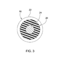
Fig. 1 , - Fig. 3
- is a view taken along lines 3-3 of the linkage assembly of
Fig. 2 , - Fig. 4
- is a partially sectional view of a second embodiment of the linkage assembly according to the present invention,
- Fig. 5
- is an end view of the linkage assembly of
Fig. 4 , - Fig. 6
- is a view taken along lines 6-6 of the linkage assembly of
Fig. 4 , and - Fig. 7
- is a view taken along lines 7-7 of the linkage assembly of
Fig. 4 . - Referring to
Figs. 1 to 3 , alinkage assembly 10 couples aplunger 12 of an actuator, such as abrake valve 14, to an input member, such as a manually operatedbrake input member 16, such as a brake pedal. Thelinkage assembly 10 includes apushrod 18 and aresilient member 20 or elastomeric element. Thepush rod 18 preferably has a circular cross sectional shape. Thepushrod 18 has a larger diametermain body 22 and a smaller diameter end member orend portion 24. Theend portion 24 is joined to themain body 22 by anannular shoulder 26. Thepushrod 18 has anouter end 27 which is engagable with theplunger 12. - The
resilient member 20 is ahollow sleeve 28 which receives and surrounds theend portion 24 of thepushrod 18. Thesleeve 28 has an axial length which is longer than an axial length of theend portion 24. Thesleeve 28 has aninner end 30 which engages theannular shoulder 26. Thesleeve 28 has anouter end 32 which is engagable with a surface of theplunger 12. Theouter end 32 is spaced apart axially outwardly from theouter end 27 of thepushrod 18. Thus, theresilient member 20 is coupled to thepushrod 18, and theresilient member 20 has anouter end 32 which is engagable with theplunger 12 when thepushrod 18 is spaced apart from theplunger 12. Theresilient member 20 deforms to allow thepushrod 18 to directly engage theplunger 12 when thepushrod 18 is moved towards theplunger 12. - Thus, in this first embodiment, a tube-shaped rubber (or other elastomeric)
element 28 is installed onto a reduced diameter on theend portion 24 of thepushrod 18. Theelastomeric tube 28 extends beyond theouter end 24 of thepushrod 18 so that during normal operations without thebrake pedal 16 applied, theelastomeric tube 28 holds themetal pushrod 18 off of the surface of themetal plunger 12 on thebrake valve 14. - During braking, the
elastomeric tube 28 compresses, allowing themetal pushrod 18 to travel down until it contacts the brake valve plunger 12 and then depresses theplunger 12. This provides a solid, durable metal to metal interface to transmit the high forces used for braking. Theelastomeric tube 28 can be a relatively soft rubber or other material that provides good vibration damping without needing to have high wear resistance or high compressive strength, as it does not transmit much force. Also, because theelastomeric tube 28 is not pinched between thepushrod 18 and theplunger 12, theelastomeric tube 28 can flex to take up some of the 'scrubbing' motion, reducing the wear on its surfaces. - Referring now to
Figs. 4 to 7 , thepushrod 40 has ahollow end 42 in which is formed ablind bore 44 which opens towards theplunger 12. Theblind bore 44 includes a larger diameter axiallyouter bore 46 and a smaller diameter axiallyinner bore 48. Anend portion 47 of thepushrod 40 is tapered and terminates at an annular end orcontact surface 49. - A solid
resilient member 50 is received by theblind bore 44. Theresilient member 50 has an axial length which is longer than an axial length of theblind bore 44. Theresilient member 50 has anouter end 52 which is external to theblind bore 44 when thepushrod 40 is spaced apart from theplunger 12. - The
resilient member 50 includes an axiallyinner part 54 and an axiallyouter part 56. Theinner part 54 engages a wall of theinner bore 48. Theouter part 56 is spaced apart from a wall of theouter bore 46. Theinner part 54 is received and compressed byinner bore 48. Preferably, theresilient member 50 may have a polygonal cross-sectional shape which forms a plurality ofcorners 58. Theresilient member 50 may have a quadrilateral polygonal cross-sectional shape. As best seen inFig. 6 , thecorners 58 engage and are compressed by the wall of theinner bore 48. - Thus, in this second embodiment, a rubber (or other elastomeric)
element 50 is inserted into ablind bore 44 drilled in theend portion 47 of thepushrod 18. Theelastomeric element 50 extends beyond the outer end of thepushrod 18 so that during normal operations without the brake pedal applied, theelastomeric element 50 holds themetal pushrod 18 off of the surface of themetal plunger 12 on thebrake valve 14, isolating thepushrod 18 andbrake pedal 16 from vibration. - The
elastomeric element 50 is a rubber part that may have a square cross section. The blind bore 44 in the outer end of thepushrod 18 is stepped, with an larger diameter outer bore 46 and an smaller diameterinner bore 48. The larger diameter outer bore 46 at the outer end of thepushrod 18 has a diameter larger than the corner-to-corner size of theelastomeric element 50. This provides room for theelastomeric element 50 to compress without becoming bound up due to friction on the sides of the larger diameter outer bore 46. The smaller diameter inner bore 48 is sized so that thecorners 58 of the square section of theelastomeric element 50 will engage and be compressed by the sides of the smaller diameterinner bore 48. This provides a press fit which holds theelastomeric element 50 into thepushrod 18. The inner bore diameter, however, is larger than the flat-to-flat dimension of such rubber square element. This allows areas for air to be pushed past theelastomeric element 50 as it is being installed into theinner bore 48, preventing a situation where air is trapped and compressed behind theelastomeric element 50, preventing it from being installed fully. - During braking, the
elastomeric element 50 compresses into thepushrod 18 within the larger diameter outer bore 46 so that thepushrod 18 can move towards and contact thebrake valve plunger 12 directly. This provides a solid, durable, metal to metal interface to transmit the high forces used for braking. Theelastomeric element 50 may be relatively soft material (rubber or other materials) which provides good vibration damping without needing to have high wear resistance or high compressive strength, as it does not transmit much force. - In both embodiments, the
resilient member - The result is
linkage assembly 10 which includes an elastomeric element to dampen vibration between abrake valve 14 and abrake pedal 16 in the cab of an agricultural vehicle. Thelinkage assembly 10 forms together with 14 and 16 a brake control system of the agricultural vehicle.
Claims (13)
- A linkage assembly for coupling a plunger of an actuator to a manually operated input member, the linkage assembly (10) comprising a pushrod (18); and a resilient member (20; 50) coupled to the pushrod (18), the resilient member (20; 50) having an outer end (27; 52) which is engagable with the plunger (14) when the pushrod (18) is spaced apart from the plunger (14), the resilient member (20; 50) deforming to allow the pushrod (18) to directly engage the plunger (14) when the pushrod (18) is moved towards the plunger (14).
- The linkage assembly according to claim 1, characterized in that the resilient member (20) comprises a hollow sleeve (28) which receives an end portion (24) of the pushrod (18).
- The linkage assembly according to claim 1, characterized in that the pushrod (18) comprises a larger diameter main body (22) and a smaller diameter end portion (24), and the resilient member (20) comprises a hollow sleeve (28) which receives the smaller diameter end portion (24) of the pushrod (18).
- The linkage assembly according to claim 2 or 3, characterized in that the hollow sleeve (28) has an axial length which is longer than an axial length of the end portion (24).
- The linkage assembly according to at least one of claims 2 to 4, characterized in that the end portion (24) is joined to the main body (22) by an annular shoulder (26), and an outer end (32) of the hollow sleeve (28) engages the annular shoulder (26).
- The linkage assembly according to claim 1, characterized in that the pushrod (18) includes a blind bore (44) which opens towards the plunger (12), and the resilient member (50) is received by the blind bore (44), an outer end (52) of the resilient member (50) being external to the blind bore (44) when the pushrod (18) is spaced apart from the plunger (12).
- The linkage assembly according to claim 6, characterized in that the blind bore (44) comprises a larger diameter outer bore (46) and a smaller diameter inner bore (48), and the resilient member (50) comprises an axially inner part (54) and an axially outer part (56), the inner part (54) engaging a wall of the inner bore (48).
- The linkage assembly according to claim 7, characterized in that the outer part (56) is spaced apart from a wall of the outer bore (46).
- The linkage assembly according to at least one of claims 6 to 8, characterized in that the resilient member (50) has an axial length which is longer than an axial length of the blind bore (44).
- The linkage assembly according to at least one of claims 6 to 9, characterized in that the resilient member (50) has an inner end which is received and compressed by an inner end of the blind bore (44).
- The linkage assembly according to at least one of claims 6 to 10, characterized in that the resilient member (50) has a polygonal or quadrilateral polygonal cross-sectional shape.
- The linkage assembly according to at least one of claims 6 to 11, characterized in that the resilient member (50) has corners (58) which engage a wall of the blind bore (44).
- The linkage assembly according to claim 12, characterized in that the blind bore (44) comprises a larger diameter outer bore (46) and a smaller diameter inner bore (48), and the smaller diameter inner bore (48) has a diameter which is smaller than a corner to corner dimension of the resilient member (50).
Applications Claiming Priority (1)
| Application Number | Priority Date | Filing Date | Title |
|---|---|---|---|
| US14/553,017 US9802585B2 (en) | 2014-11-25 | 2014-11-25 | Linkage assembly |
Publications (2)
| Publication Number | Publication Date |
|---|---|
| EP3028911A1 true EP3028911A1 (en) | 2016-06-08 |
| EP3028911B1 EP3028911B1 (en) | 2018-08-01 |
Family
ID=54293062
Family Applications (1)
| Application Number | Title | Priority Date | Filing Date |
|---|---|---|---|
| EP15188052.3A Active EP3028911B1 (en) | 2014-11-25 | 2015-10-02 | Linkage assembly for coupling a plunger of an actuator to a manually operated input member |
Country Status (2)
| Country | Link |
|---|---|
| US (1) | US9802585B2 (en) |
| EP (1) | EP3028911B1 (en) |
Families Citing this family (1)
| Publication number | Priority date | Publication date | Assignee | Title |
|---|---|---|---|---|
| US10112587B2 (en) * | 2015-12-18 | 2018-10-30 | Hyster-Yale Group, Inc. | Electronic braking system |
Citations (4)
| Publication number | Priority date | Publication date | Assignee | Title |
|---|---|---|---|---|
| US4603600A (en) * | 1984-02-17 | 1986-08-05 | Aisin Seiki Kabushiki Kaisha | Parking brake operating device |
| DE19543698C1 (en) * | 1995-11-23 | 1997-03-20 | Daimler Benz Ag | Brake rod between pedal and master cylinder |
| GB2309275A (en) * | 1995-11-23 | 1997-07-23 | Daimler Benz Ag | Providing "feel" at the brake pedal |
| DE102010042694A1 (en) * | 2010-07-27 | 2012-02-02 | Robert Bosch Gmbh | Coupling device for connecting a brake input element to a master cylinder and method for operating such a coupling device |
Family Cites Families (11)
| Publication number | Priority date | Publication date | Assignee | Title |
|---|---|---|---|---|
| GB550138A (en) * | 1941-06-18 | 1942-12-24 | Rover Co Ltd | Improvements relating to vehicle brake operating pedals |
| US3343564A (en) * | 1964-12-08 | 1967-09-26 | Gen Motors Corp | Ball check valve having particular spring means |
| GB1432350A (en) * | 1972-06-09 | 1976-04-14 | Automotives Products Ltd | Brake application control devices and to liquid pressure braking systems for vehicles which include such devices |
| US4752163A (en) * | 1987-05-05 | 1988-06-21 | Emerson Electric Co. | Thread cutting diestock assembly |
| JPH0813611B2 (en) * | 1988-06-21 | 1996-02-14 | 日産自動車株式会社 | Control device for automatic transmission |
| US5259195A (en) * | 1992-07-07 | 1993-11-09 | Pringle William L | Fluid pressure intensifier |
| US6840352B2 (en) * | 1999-03-02 | 2005-01-11 | Textron Inc. | Suspended pedal system for golf cars |
| US7032272B2 (en) * | 2003-03-27 | 2006-04-25 | Masco Corporation Of Indiana | Friction hinge |
| US7287457B1 (en) * | 2005-07-06 | 2007-10-30 | Kelsey-Hayes Company | Structure for retaining a piston assembly in position relative to a cylinder |
| WO2011015603A2 (en) * | 2009-08-04 | 2011-02-10 | Eaton Srl | Lost motion valve control apparatus |
| US8393449B2 (en) * | 2011-07-07 | 2013-03-12 | Sram, Llc | Variable rate linkage for a brake system for a handlebar-steered vehicle |
-
2014
- 2014-11-25 US US14/553,017 patent/US9802585B2/en active Active
-
2015
- 2015-10-02 EP EP15188052.3A patent/EP3028911B1/en active Active
Patent Citations (4)
| Publication number | Priority date | Publication date | Assignee | Title |
|---|---|---|---|---|
| US4603600A (en) * | 1984-02-17 | 1986-08-05 | Aisin Seiki Kabushiki Kaisha | Parking brake operating device |
| DE19543698C1 (en) * | 1995-11-23 | 1997-03-20 | Daimler Benz Ag | Brake rod between pedal and master cylinder |
| GB2309275A (en) * | 1995-11-23 | 1997-07-23 | Daimler Benz Ag | Providing "feel" at the brake pedal |
| DE102010042694A1 (en) * | 2010-07-27 | 2012-02-02 | Robert Bosch Gmbh | Coupling device for connecting a brake input element to a master cylinder and method for operating such a coupling device |
Also Published As
| Publication number | Publication date |
|---|---|
| US9802585B2 (en) | 2017-10-31 |
| US20160144837A1 (en) | 2016-05-26 |
| EP3028911B1 (en) | 2018-08-01 |
Similar Documents
| Publication | Publication Date | Title |
|---|---|---|
| US9518628B2 (en) | Tubular vibration-damping device | |
| KR102223847B1 (en) | Pedal simulator | |
| US20160009157A1 (en) | Dual-Rate Jounce Bumper | |
| EP3436320A1 (en) | Braking force simulator for a motor vehicle | |
| US6843352B2 (en) | Two stage shock absorber mount | |
| JPH05215204A (en) | Noise vibration damping assembly for shift-lever mechanism and forming method thereof | |
| US9447836B2 (en) | Friction dampened mechanical strut | |
| EP3028911B1 (en) | Linkage assembly for coupling a plunger of an actuator to a manually operated input member | |
| EP4541308A3 (en) | Dual brake setup joint | |
| US20150217615A1 (en) | Leaf spring arrangement | |
| EP2004464B1 (en) | Brake booster device having a damping element | |
| CN104912997B (en) | Vibration isolation device | |
| CN110366515B (en) | Spring arrangement for a rail vehicle | |
| US20150300445A1 (en) | Vibration damping device | |
| WO2018206299A1 (en) | Actuation device for a vehicle braking system | |
| US11518017B2 (en) | Vibration-damped hand-held power tool | |
| KR101918303B1 (en) | Apparatus for reducing effort of clutch pedal | |
| US11001306B2 (en) | Isolation mount assembly | |
| DE102017215348A1 (en) | Air strut with acoustic bearing | |
| JP2015003546A (en) | Vehicle body reinforcement unit | |
| KR102174599B1 (en) | Intermediate shaft of Steering apparatus for vehicle | |
| US9579944B2 (en) | System and method for attaching a control element of an air spring with internal height regulating valve | |
| US10369685B2 (en) | Spring compressor and method of use thereof | |
| DE102007010513A1 (en) | Actuation unit for a motor vehicle brake system | |
| KR20160134736A (en) | Leaf spring and mount |
Legal Events
| Date | Code | Title | Description |
|---|---|---|---|
| PUAI | Public reference made under article 153(3) epc to a published international application that has entered the european phase |
Free format text: ORIGINAL CODE: 0009012 |
|
| AK | Designated contracting states |
Kind code of ref document: A1 Designated state(s): AL AT BE BG CH CY CZ DE DK EE ES FI FR GB GR HR HU IE IS IT LI LT LU LV MC MK MT NL NO PL PT RO RS SE SI SK SM TR |
|
| AX | Request for extension of the european patent |
Extension state: BA ME |
|
| 17P | Request for examination filed |
Effective date: 20161208 |
|
| RBV | Designated contracting states (corrected) |
Designated state(s): AL AT BE BG CH CY CZ DE DK EE ES FI FR GB GR HR HU IE IS IT LI LT LU LV MC MK MT NL NO PL PT RO RS SE SI SK SM TR |
|
| GRAP | Despatch of communication of intention to grant a patent |
Free format text: ORIGINAL CODE: EPIDOSNIGR1 |
|
| INTG | Intention to grant announced |
Effective date: 20180301 |
|
| GRAS | Grant fee paid |
Free format text: ORIGINAL CODE: EPIDOSNIGR3 |
|
| GRAA | (expected) grant |
Free format text: ORIGINAL CODE: 0009210 |
|
| AK | Designated contracting states |
Kind code of ref document: B1 Designated state(s): AL AT BE BG CH CY CZ DE DK EE ES FI FR GB GR HR HU IE IS IT LI LT LU LV MC MK MT NL NO PL PT RO RS SE SI SK SM TR |
|
| REG | Reference to a national code |
Ref country code: GB Ref legal event code: FG4D |
|
| REG | Reference to a national code |
Ref country code: CH Ref legal event code: EP Ref country code: AT Ref legal event code: REF Ref document number: 1023917 Country of ref document: AT Kind code of ref document: T Effective date: 20180815 |
|
| REG | Reference to a national code |
Ref country code: IE Ref legal event code: FG4D |
|
| REG | Reference to a national code |
Ref country code: DE Ref legal event code: R096 Ref document number: 602015014222 Country of ref document: DE |
|
| REG | Reference to a national code |
Ref country code: NL Ref legal event code: MP Effective date: 20180801 |
|
| REG | Reference to a national code |
Ref country code: LT Ref legal event code: MG4D |
|
| REG | Reference to a national code |
Ref country code: AT Ref legal event code: MK05 Ref document number: 1023917 Country of ref document: AT Kind code of ref document: T Effective date: 20180801 |
|
| PG25 | Lapsed in a contracting state [announced via postgrant information from national office to epo] |
Ref country code: PL Free format text: LAPSE BECAUSE OF FAILURE TO SUBMIT A TRANSLATION OF THE DESCRIPTION OR TO PAY THE FEE WITHIN THE PRESCRIBED TIME-LIMIT Effective date: 20180801 Ref country code: LT Free format text: LAPSE BECAUSE OF FAILURE TO SUBMIT A TRANSLATION OF THE DESCRIPTION OR TO PAY THE FEE WITHIN THE PRESCRIBED TIME-LIMIT Effective date: 20180801 Ref country code: AT Free format text: LAPSE BECAUSE OF FAILURE TO SUBMIT A TRANSLATION OF THE DESCRIPTION OR TO PAY THE FEE WITHIN THE PRESCRIBED TIME-LIMIT Effective date: 20180801 Ref country code: SE Free format text: LAPSE BECAUSE OF FAILURE TO SUBMIT A TRANSLATION OF THE DESCRIPTION OR TO PAY THE FEE WITHIN THE PRESCRIBED TIME-LIMIT Effective date: 20180801 Ref country code: NO Free format text: LAPSE BECAUSE OF FAILURE TO SUBMIT A TRANSLATION OF THE DESCRIPTION OR TO PAY THE FEE WITHIN THE PRESCRIBED TIME-LIMIT Effective date: 20181101 Ref country code: NL Free format text: LAPSE BECAUSE OF FAILURE TO SUBMIT A TRANSLATION OF THE DESCRIPTION OR TO PAY THE FEE WITHIN THE PRESCRIBED TIME-LIMIT Effective date: 20180801 Ref country code: IS Free format text: LAPSE BECAUSE OF FAILURE TO SUBMIT A TRANSLATION OF THE DESCRIPTION OR TO PAY THE FEE WITHIN THE PRESCRIBED TIME-LIMIT Effective date: 20181201 Ref country code: BG Free format text: LAPSE BECAUSE OF FAILURE TO SUBMIT A TRANSLATION OF THE DESCRIPTION OR TO PAY THE FEE WITHIN THE PRESCRIBED TIME-LIMIT Effective date: 20181101 Ref country code: FI Free format text: LAPSE BECAUSE OF FAILURE TO SUBMIT A TRANSLATION OF THE DESCRIPTION OR TO PAY THE FEE WITHIN THE PRESCRIBED TIME-LIMIT Effective date: 20180801 Ref country code: GR Free format text: LAPSE BECAUSE OF FAILURE TO SUBMIT A TRANSLATION OF THE DESCRIPTION OR TO PAY THE FEE WITHIN THE PRESCRIBED TIME-LIMIT Effective date: 20181102 Ref country code: RS Free format text: LAPSE BECAUSE OF FAILURE TO SUBMIT A TRANSLATION OF THE DESCRIPTION OR TO PAY THE FEE WITHIN THE PRESCRIBED TIME-LIMIT Effective date: 20180801 |
|
| PG25 | Lapsed in a contracting state [announced via postgrant information from national office to epo] |
Ref country code: LV Free format text: LAPSE BECAUSE OF FAILURE TO SUBMIT A TRANSLATION OF THE DESCRIPTION OR TO PAY THE FEE WITHIN THE PRESCRIBED TIME-LIMIT Effective date: 20180801 Ref country code: HR Free format text: LAPSE BECAUSE OF FAILURE TO SUBMIT A TRANSLATION OF THE DESCRIPTION OR TO PAY THE FEE WITHIN THE PRESCRIBED TIME-LIMIT Effective date: 20180801 Ref country code: AL Free format text: LAPSE BECAUSE OF FAILURE TO SUBMIT A TRANSLATION OF THE DESCRIPTION OR TO PAY THE FEE WITHIN THE PRESCRIBED TIME-LIMIT Effective date: 20180801 |
|
| PG25 | Lapsed in a contracting state [announced via postgrant information from national office to epo] |
Ref country code: ES Free format text: LAPSE BECAUSE OF FAILURE TO SUBMIT A TRANSLATION OF THE DESCRIPTION OR TO PAY THE FEE WITHIN THE PRESCRIBED TIME-LIMIT Effective date: 20180801 Ref country code: EE Free format text: LAPSE BECAUSE OF FAILURE TO SUBMIT A TRANSLATION OF THE DESCRIPTION OR TO PAY THE FEE WITHIN THE PRESCRIBED TIME-LIMIT Effective date: 20180801 Ref country code: IT Free format text: LAPSE BECAUSE OF FAILURE TO SUBMIT A TRANSLATION OF THE DESCRIPTION OR TO PAY THE FEE WITHIN THE PRESCRIBED TIME-LIMIT Effective date: 20180801 Ref country code: RO Free format text: LAPSE BECAUSE OF FAILURE TO SUBMIT A TRANSLATION OF THE DESCRIPTION OR TO PAY THE FEE WITHIN THE PRESCRIBED TIME-LIMIT Effective date: 20180801 Ref country code: CZ Free format text: LAPSE BECAUSE OF FAILURE TO SUBMIT A TRANSLATION OF THE DESCRIPTION OR TO PAY THE FEE WITHIN THE PRESCRIBED TIME-LIMIT Effective date: 20180801 |
|
| REG | Reference to a national code |
Ref country code: DE Ref legal event code: R097 Ref document number: 602015014222 Country of ref document: DE |
|
| PG25 | Lapsed in a contracting state [announced via postgrant information from national office to epo] |
Ref country code: SK Free format text: LAPSE BECAUSE OF FAILURE TO SUBMIT A TRANSLATION OF THE DESCRIPTION OR TO PAY THE FEE WITHIN THE PRESCRIBED TIME-LIMIT Effective date: 20180801 Ref country code: SM Free format text: LAPSE BECAUSE OF FAILURE TO SUBMIT A TRANSLATION OF THE DESCRIPTION OR TO PAY THE FEE WITHIN THE PRESCRIBED TIME-LIMIT Effective date: 20180801 Ref country code: DK Free format text: LAPSE BECAUSE OF FAILURE TO SUBMIT A TRANSLATION OF THE DESCRIPTION OR TO PAY THE FEE WITHIN THE PRESCRIBED TIME-LIMIT Effective date: 20180801 |
|
| REG | Reference to a national code |
Ref country code: CH Ref legal event code: PL |
|
| PLBE | No opposition filed within time limit |
Free format text: ORIGINAL CODE: 0009261 |
|
| STAA | Information on the status of an ep patent application or granted ep patent |
Free format text: STATUS: NO OPPOSITION FILED WITHIN TIME LIMIT |
|
| REG | Reference to a national code |
Ref country code: BE Ref legal event code: MM Effective date: 20181031 |
|
| PG25 | Lapsed in a contracting state [announced via postgrant information from national office to epo] |
Ref country code: LU Free format text: LAPSE BECAUSE OF NON-PAYMENT OF DUE FEES Effective date: 20181002 Ref country code: MC Free format text: LAPSE BECAUSE OF FAILURE TO SUBMIT A TRANSLATION OF THE DESCRIPTION OR TO PAY THE FEE WITHIN THE PRESCRIBED TIME-LIMIT Effective date: 20180801 |
|
| 26N | No opposition filed |
Effective date: 20190503 |
|
| REG | Reference to a national code |
Ref country code: IE Ref legal event code: MM4A |
|
| PG25 | Lapsed in a contracting state [announced via postgrant information from national office to epo] |
Ref country code: SI Free format text: LAPSE BECAUSE OF FAILURE TO SUBMIT A TRANSLATION OF THE DESCRIPTION OR TO PAY THE FEE WITHIN THE PRESCRIBED TIME-LIMIT Effective date: 20180801 Ref country code: BE Free format text: LAPSE BECAUSE OF NON-PAYMENT OF DUE FEES Effective date: 20181031 Ref country code: CH Free format text: LAPSE BECAUSE OF NON-PAYMENT OF DUE FEES Effective date: 20181031 Ref country code: FR Free format text: LAPSE BECAUSE OF NON-PAYMENT OF DUE FEES Effective date: 20181031 Ref country code: LI Free format text: LAPSE BECAUSE OF NON-PAYMENT OF DUE FEES Effective date: 20181031 |
|
| PG25 | Lapsed in a contracting state [announced via postgrant information from national office to epo] |
Ref country code: IE Free format text: LAPSE BECAUSE OF NON-PAYMENT OF DUE FEES Effective date: 20181002 |
|
| PG25 | Lapsed in a contracting state [announced via postgrant information from national office to epo] |
Ref country code: MT Free format text: LAPSE BECAUSE OF NON-PAYMENT OF DUE FEES Effective date: 20181002 |
|
| PG25 | Lapsed in a contracting state [announced via postgrant information from national office to epo] |
Ref country code: TR Free format text: LAPSE BECAUSE OF FAILURE TO SUBMIT A TRANSLATION OF THE DESCRIPTION OR TO PAY THE FEE WITHIN THE PRESCRIBED TIME-LIMIT Effective date: 20180801 |
|
| PG25 | Lapsed in a contracting state [announced via postgrant information from national office to epo] |
Ref country code: PT Free format text: LAPSE BECAUSE OF FAILURE TO SUBMIT A TRANSLATION OF THE DESCRIPTION OR TO PAY THE FEE WITHIN THE PRESCRIBED TIME-LIMIT Effective date: 20180801 |
|
| PG25 | Lapsed in a contracting state [announced via postgrant information from national office to epo] |
Ref country code: MK Free format text: LAPSE BECAUSE OF NON-PAYMENT OF DUE FEES Effective date: 20180801 Ref country code: HU Free format text: LAPSE BECAUSE OF FAILURE TO SUBMIT A TRANSLATION OF THE DESCRIPTION OR TO PAY THE FEE WITHIN THE PRESCRIBED TIME-LIMIT; INVALID AB INITIO Effective date: 20151002 Ref country code: CY Free format text: LAPSE BECAUSE OF FAILURE TO SUBMIT A TRANSLATION OF THE DESCRIPTION OR TO PAY THE FEE WITHIN THE PRESCRIBED TIME-LIMIT Effective date: 20180801 |
|
| GBPC | Gb: european patent ceased through non-payment of renewal fee |
Effective date: 20191002 |
|
| PG25 | Lapsed in a contracting state [announced via postgrant information from national office to epo] |
Ref country code: GB Free format text: LAPSE BECAUSE OF NON-PAYMENT OF DUE FEES Effective date: 20191002 |
|
| PGFP | Annual fee paid to national office [announced via postgrant information from national office to epo] |
Ref country code: DE Payment date: 20250919 Year of fee payment: 11 |