EP3028892A1 - Verfahren zur positionierung eines kraftfahrzeugs in einer ladeposition und kraftfahrzeug - Google Patents
Verfahren zur positionierung eines kraftfahrzeugs in einer ladeposition und kraftfahrzeug Download PDFInfo
- Publication number
- EP3028892A1 EP3028892A1 EP15003392.6A EP15003392A EP3028892A1 EP 3028892 A1 EP3028892 A1 EP 3028892A1 EP 15003392 A EP15003392 A EP 15003392A EP 3028892 A1 EP3028892 A1 EP 3028892A1
- Authority
- EP
- European Patent Office
- Prior art keywords
- motor vehicle
- position information
- loading
- detection
- trajectory
- Prior art date
- Legal status (The legal status is an assumption and is not a legal conclusion. Google has not performed a legal analysis and makes no representation as to the accuracy of the status listed.)
- Granted
Links
- 238000000034 method Methods 0.000 title claims abstract description 39
- 238000001514 detection method Methods 0.000 claims abstract description 74
- 230000001419 dependent effect Effects 0.000 claims abstract description 13
- 238000004146 energy storage Methods 0.000 claims description 8
- 230000005540 biological transmission Effects 0.000 claims description 4
- 238000011156 evaluation Methods 0.000 claims description 3
- 238000004891 communication Methods 0.000 description 6
- 230000007613 environmental effect Effects 0.000 description 5
- 238000004364 calculation method Methods 0.000 description 2
- 238000012546 transfer Methods 0.000 description 2
- 238000010276 construction Methods 0.000 description 1
- 238000012937 correction Methods 0.000 description 1
- 238000013461 design Methods 0.000 description 1
- 238000011161 development Methods 0.000 description 1
- 238000010586 diagram Methods 0.000 description 1
- 230000005672 electromagnetic field Effects 0.000 description 1
- 230000006698 induction Effects 0.000 description 1
- 239000003550 marker Substances 0.000 description 1
- 238000012544 monitoring process Methods 0.000 description 1
- 230000035515 penetration Effects 0.000 description 1
- 238000012545 processing Methods 0.000 description 1
- 230000001360 synchronised effect Effects 0.000 description 1
Images

Classifications
-
- B—PERFORMING OPERATIONS; TRANSPORTING
- B60—VEHICLES IN GENERAL
- B60L—PROPULSION OF ELECTRICALLY-PROPELLED VEHICLES; SUPPLYING ELECTRIC POWER FOR AUXILIARY EQUIPMENT OF ELECTRICALLY-PROPELLED VEHICLES; ELECTRODYNAMIC BRAKE SYSTEMS FOR VEHICLES IN GENERAL; MAGNETIC SUSPENSION OR LEVITATION FOR VEHICLES; MONITORING OPERATING VARIABLES OF ELECTRICALLY-PROPELLED VEHICLES; ELECTRIC SAFETY DEVICES FOR ELECTRICALLY-PROPELLED VEHICLES
- B60L53/00—Methods of charging batteries, specially adapted for electric vehicles; Charging stations or on-board charging equipment therefor; Exchange of energy storage elements in electric vehicles
- B60L53/30—Constructional details of charging stations
- B60L53/35—Means for automatic or assisted adjustment of the relative position of charging devices and vehicles
- B60L53/37—Means for automatic or assisted adjustment of the relative position of charging devices and vehicles using optical position determination, e.g. using cameras
-
- B—PERFORMING OPERATIONS; TRANSPORTING
- B60—VEHICLES IN GENERAL
- B60L—PROPULSION OF ELECTRICALLY-PROPELLED VEHICLES; SUPPLYING ELECTRIC POWER FOR AUXILIARY EQUIPMENT OF ELECTRICALLY-PROPELLED VEHICLES; ELECTRODYNAMIC BRAKE SYSTEMS FOR VEHICLES IN GENERAL; MAGNETIC SUSPENSION OR LEVITATION FOR VEHICLES; MONITORING OPERATING VARIABLES OF ELECTRICALLY-PROPELLED VEHICLES; ELECTRIC SAFETY DEVICES FOR ELECTRICALLY-PROPELLED VEHICLES
- B60L53/00—Methods of charging batteries, specially adapted for electric vehicles; Charging stations or on-board charging equipment therefor; Exchange of energy storage elements in electric vehicles
- B60L53/10—Methods of charging batteries, specially adapted for electric vehicles; Charging stations or on-board charging equipment therefor; Exchange of energy storage elements in electric vehicles characterised by the energy transfer between the charging station and the vehicle
- B60L53/12—Inductive energy transfer
- B60L53/126—Methods for pairing a vehicle and a charging station, e.g. establishing a one-to-one relation between a wireless power transmitter and a wireless power receiver
-
- B—PERFORMING OPERATIONS; TRANSPORTING
- B60—VEHICLES IN GENERAL
- B60L—PROPULSION OF ELECTRICALLY-PROPELLED VEHICLES; SUPPLYING ELECTRIC POWER FOR AUXILIARY EQUIPMENT OF ELECTRICALLY-PROPELLED VEHICLES; ELECTRODYNAMIC BRAKE SYSTEMS FOR VEHICLES IN GENERAL; MAGNETIC SUSPENSION OR LEVITATION FOR VEHICLES; MONITORING OPERATING VARIABLES OF ELECTRICALLY-PROPELLED VEHICLES; ELECTRIC SAFETY DEVICES FOR ELECTRICALLY-PROPELLED VEHICLES
- B60L53/00—Methods of charging batteries, specially adapted for electric vehicles; Charging stations or on-board charging equipment therefor; Exchange of energy storage elements in electric vehicles
- B60L53/30—Constructional details of charging stations
- B60L53/35—Means for automatic or assisted adjustment of the relative position of charging devices and vehicles
- B60L53/36—Means for automatic or assisted adjustment of the relative position of charging devices and vehicles by positioning the vehicle
-
- Y—GENERAL TAGGING OF NEW TECHNOLOGICAL DEVELOPMENTS; GENERAL TAGGING OF CROSS-SECTIONAL TECHNOLOGIES SPANNING OVER SEVERAL SECTIONS OF THE IPC; TECHNICAL SUBJECTS COVERED BY FORMER USPC CROSS-REFERENCE ART COLLECTIONS [XRACs] AND DIGESTS
- Y02—TECHNOLOGIES OR APPLICATIONS FOR MITIGATION OR ADAPTATION AGAINST CLIMATE CHANGE
- Y02T—CLIMATE CHANGE MITIGATION TECHNOLOGIES RELATED TO TRANSPORTATION
- Y02T10/00—Road transport of goods or passengers
- Y02T10/60—Other road transportation technologies with climate change mitigation effect
- Y02T10/70—Energy storage systems for electromobility, e.g. batteries
-
- Y—GENERAL TAGGING OF NEW TECHNOLOGICAL DEVELOPMENTS; GENERAL TAGGING OF CROSS-SECTIONAL TECHNOLOGIES SPANNING OVER SEVERAL SECTIONS OF THE IPC; TECHNICAL SUBJECTS COVERED BY FORMER USPC CROSS-REFERENCE ART COLLECTIONS [XRACs] AND DIGESTS
- Y02—TECHNOLOGIES OR APPLICATIONS FOR MITIGATION OR ADAPTATION AGAINST CLIMATE CHANGE
- Y02T—CLIMATE CHANGE MITIGATION TECHNOLOGIES RELATED TO TRANSPORTATION
- Y02T10/00—Road transport of goods or passengers
- Y02T10/60—Other road transportation technologies with climate change mitigation effect
- Y02T10/7072—Electromobility specific charging systems or methods for batteries, ultracapacitors, supercapacitors or double-layer capacitors
-
- Y—GENERAL TAGGING OF NEW TECHNOLOGICAL DEVELOPMENTS; GENERAL TAGGING OF CROSS-SECTIONAL TECHNOLOGIES SPANNING OVER SEVERAL SECTIONS OF THE IPC; TECHNICAL SUBJECTS COVERED BY FORMER USPC CROSS-REFERENCE ART COLLECTIONS [XRACs] AND DIGESTS
- Y02—TECHNOLOGIES OR APPLICATIONS FOR MITIGATION OR ADAPTATION AGAINST CLIMATE CHANGE
- Y02T—CLIMATE CHANGE MITIGATION TECHNOLOGIES RELATED TO TRANSPORTATION
- Y02T90/00—Enabling technologies or technologies with a potential or indirect contribution to GHG emissions mitigation
- Y02T90/10—Technologies relating to charging of electric vehicles
- Y02T90/12—Electric charging stations
-
- Y—GENERAL TAGGING OF NEW TECHNOLOGICAL DEVELOPMENTS; GENERAL TAGGING OF CROSS-SECTIONAL TECHNOLOGIES SPANNING OVER SEVERAL SECTIONS OF THE IPC; TECHNICAL SUBJECTS COVERED BY FORMER USPC CROSS-REFERENCE ART COLLECTIONS [XRACs] AND DIGESTS
- Y02—TECHNOLOGIES OR APPLICATIONS FOR MITIGATION OR ADAPTATION AGAINST CLIMATE CHANGE
- Y02T—CLIMATE CHANGE MITIGATION TECHNOLOGIES RELATED TO TRANSPORTATION
- Y02T90/00—Enabling technologies or technologies with a potential or indirect contribution to GHG emissions mitigation
- Y02T90/10—Technologies relating to charging of electric vehicles
- Y02T90/14—Plug-in electric vehicles
Definitions
- the invention relates to a method for positioning a motor vehicle in a charging position suitable for contactless charging of an energy storage device of the motor vehicle by a loading plate and an associated motor vehicle.
- Hybrid vehicles and purely electrically powered vehicles include energy storage devices that provide electrical energy for operation of the motor vehicle.
- a convenient way to charge these energy storage is a contactless charging, in which the motor vehicle is positioned above or adjacent to an infrastructure-side pallet and a contactless energy transfer from the infrastructure-side pallet to a vehicle-side pallet.
- a contactless charging in which the motor vehicle is positioned above or adjacent to an infrastructure-side pallet and a contactless energy transfer from the infrastructure-side pallet to a vehicle-side pallet.
- infrastructure-side pallets and motor vehicles may include systems that assist a driver in positioning the motor vehicle with respect to the pallet.
- position detection systems are used on a radio basis.
- the invention is therefore based on the object of specifying a method for positioning a motor vehicle with respect to a pallet, which in contrast is improved with respect to the range of a position detection and still allows exact positioning of the motor vehicle.
- the first and / or the second detection device may be motor vehicle-side detection devices.
- the first and / or the second detection device may be loading plate-side detection devices.
- the first and / or the second detection device may be formed as an infrastructure device formed separately from the loading plate or as part of such. If an off-vehicle detection device is used as the first and / or second detection device, the first and / or second position information can be transmitted wirelessly to the motor vehicle after it has been detected.
- the first detection device can evaluate sensor information, in particular image data from motor vehicle sensors, in order to determine a first position information.
- the first position information may be relatively inaccurate. Nevertheless, the first position information already allows guidance of the motor vehicle in the direction of the loading position. The motor vehicle is thus guided into an area which lies within the second detection range of the second detection device.
- the second detection device can be, for example, an initially explained system for radio-signal-based position detection.
- the second position information may be more accurate than the first position information, that is, describing the actual relative position of the loading position to the motor vehicle with a lower error than the first position information. In the method according to the invention, a coarse positioning and subsequently a fine positioning can thus be carried out first.
- the position information can only describe a relative position of the loading position to the motor vehicle, but preferably also a relative orientation is taken into account.
- the positioning of the motor vehicle can preferably take place in such a way that a continuous forward or reverse travel to the loading position is made possible.
- the first or the second position information is determined repeatedly during the guidance of the motor vehicle and for the guidance of the motor vehicle to be adapted accordingly.
- the steps a and b or c and d are repeatedly performed, wherein in the steps a and c respectively updated first or second position information is detected and in the steps b and d respectively a guide in response to this updated position information.
- the driveability of a planned trajectory and / or the feasibility of planned driving maneuvers can be checked, wherein further environmental data, such as the positions and dimensions of other road users and / or infrastructure facilities can be taken into account.
- the first detection device comprises at least one sensor device, in particular at least one camera, by which environmental data relating to the motor vehicle environment are detected, whereafter the first position information is determined as a function of the environmental data.
- a position of the loading plate or a position of a marking associated with the loading plate can be detected in the surrounding data, for example by an image recognition algorithm. The first position information can then be determined depending on the detected position of the pallet or the marker.
- the second detection device may comprise at least one receiving device for receiving a radio signal emitted by one of the loading plate or the motor vehicle, wherein the second position information is determined by evaluation of the radio signal by the second detection device.
- the radio signal may, in particular, be a radio signal emitted by a communication device of the charging plate, which is used for communication with a vehicle-side device during the charging process.
- the second detection device is a charging-plate-side or otherwise infrastructure-side detection device, wherein the receiving device receives radio signals transmitted by a transmission device assigned to the motor vehicle.
- the radio signal may be a radio signal that is emitted by a communication device of the motor vehicle, which is used for communication with a loading plate side device during the charging process.
- an induction coil of the pallet which serves to transfer energy to the motor vehicle in the context of positioning electromagnetic fields and to detect this by one or more motor vehicle-side devices, for example, to determine the second position information from relative reception amplitudes.
- the second receiving device can have a plurality of the receiving devices for receiving the radio signal, wherein the second position information is determined as a function of reception strengths of the radio signal on and / or signal propagation times of the radio signal to the receiving devices. In particular, relative terms or reception strengths can be determined.
- it would be possible to determine absolute transit times for example, by having time information synchronized on the charging plate side and on the motor vehicle side, wherein a transit time can be determined directly from a difference between the transmission time and the reception time. A synchronization of times is possible for example by GPS signals.
- Another way to determine a transit time is to provide an automatic response to a received radio signal and then to detect the total transit time of the transmission signal and the response signal.
- the guidance of the motor vehicle can take place such that when the second detection range is reached, the kinematic maximum possibilities for correcting the vehicle guidance are available, that is, errors in the detection of the first position information in the context of the guidance of the motor vehicle on the basis of the second position information can be compensated. It is therefore possible for the guidance of the motor vehicle in step b to take place along a trajectory from the current motor vehicle position to the loading position, wherein the trajectory is determined and / or adapted by the control device such that in at least a portion of the trajectory through the trajectory predetermined transverse guidance parameter of the motor vehicle is maximally spaced from a predetermined limit value for the transverse guidance parameter.
- the value for the lateral guidance parameter within the section may take into account a maximum within that section, a mean value within that section, an integral or the like.
- a position can be predicted at which the trajectory reaches the second detection range.
- the section of the trajectory for which the distance between the lateral guidance parameter and the limit value is maximized can then be selected such that the section is within the range of reaching the second detection range and / or within the second detection range.
- the limit value for the transverse guidance parameter can be predetermined by design and, for example, be a maximum steering angle of the motor vehicle.
- step d the driving instruction and / or the driving engagement are additionally determined in dependence on the first position information. It is thus possible to fuse the first and the second position information, whereby the accuracy of the determination of the loading position can be further increased.
- the first and the second position information can be weighted as a function of the distance.
- step a Prior to step a can be detected by the first detection means a presence of the pallet in the vicinity of the motor vehicle, after which a utility of the pallet pending pallet reference is output to the driver of the motor vehicle, after which the method in response to an operator input of the driver with step a for guiding the Motor vehicle is continued or aborted to the non-contact charging of the energy storage by the loading plate suitable charging position.
- additional environment information is determined and evaluated by the first detection device or other sensors of the motor vehicle in order to determine availability of the loading plate, that is to say in particular whether it is already occupied by another motor vehicle.
- the invention also relates to a motor vehicle, wherein the motor vehicle comprises a control device, which is designed for carrying out a method according to the invention.
- the motor vehicle additionally comprises a first and / or a second detection device, which are designed to detect the first and / or the second position information when carrying out the method according to the invention.
- the motor vehicle according to the invention may have the features described in the context of the explanations of the method according to the invention with the advantages mentioned there.
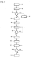
- Fig. 1 shows a flowchart of a method for positioning a motor vehicle 1 in a non-contact charging of an energy storage device of the motor vehicle 1 by a loading plate 4 suitable loading position 5.
- Fig. 2 the guidance of the motor vehicle 1 in the loading position 5 is shown schematically.
- the method shown is the clear presentation of the process, the respective driving situation with respect to Fig. 2 explained.
- a presence of the loading plate 4 in the surroundings of the motor vehicle is first detected by a first detection device of the motor vehicle 1.
- the first detection device comprises a camera 2 with a detection area 3 and an associated image processing device (not shown).
- the camera 2 captures environmental data, wherein the charge plate 4 is detected in the environment data.
- an indication to a driver of the motor vehicle 1 is output in step S2 by a device of the motor vehicle 1, for example by a display or a speaker, indicating this to the presence of the pallet 4 in the automotive environment .
- a corresponding indication can be supplemented depending on whether it is determined by evaluation of the environment data that the loading plate 4 is free, that is, that no further motor vehicle is in the loading position, or the hint can from a Charge state of the energy storage of the motor vehicle 1 dependent.
- step S3 it is determined whether a driver desires an automatic guidance of the motor vehicle or a support of the driver by driving interventions when guiding into the loading position 5. For this purpose, it is determined whether the driver responded with a corresponding operator input to the given in step S2 hint.
- any control means may be provided in the motor vehicle 1.
- the further method is similar in this case, wherein a determination of driving interventions is replaced by a determination of corresponding driving instructions.
- step S4 If a guidance of the motor vehicle 1 into the loading position 5 by a driver is not desired, for example because he wishes to continue his journey, the normal driving operation is continued in step S4. However, if guidance to the loading position 5 is desired, then in steps S5 to S12 a guidance of the motor vehicle 1 into the loading position 5 takes place.
- a first detection device which comprises the camera 2 provides a relatively coarse first position information, which, however, is already detectable in a relatively large detection range, which is represented by the circle 6.
- the motor vehicle 1 After a sufficient approximation of the motor vehicle 1 to the loading plate 4, the motor vehicle 1 reaches a second detection range represented by the circle 12, within which a second position information can be detected by a second detection device.
- the second detection device For detecting the second position information, the second detection device comprises the receiving devices 9, 10 which are arranged at a distance from one another in the motor vehicle 1. These can detect and analyze radio signals of a communication device 11 of the loading plate 4 within the second detection range, in order to determine the second position information.
- step S5 the motor vehicle 1 is as in Fig. 2 shown still relatively far away from the pallet 4.
- the motor vehicle 1 is thus located outside the second detection range, whereby no determination of the relative position of the loading position to the motor vehicle 1 is possible via the second detection device. Therefore, a determination of a first position information by the first detection device, which comprises the camera 2, first takes place in step S5.
- the first detection device which comprises the camera 2
- the relative position of the loading plate 4 is determined from image data of the camera 2 to the motor vehicle 1 and with the aid of a stored in the control device 7 motor vehicle geometry from a loading position 5 is determined, in which the motor vehicle 1 is to be performed.
- This first position information is provided to the control device 7 of the motor vehicle 1, which calculates a trajectory from the actual position of the motor vehicle 1 to the loading position 5 in step S6.
- Methods for calculating a trajectory for guiding a motor vehicle to a specific position are known in the prior art and will not be explained in detail.
- the first position information is subject to errors.
- the determination of a relative position of a loading position 5 to the motor vehicle 1 from the environment data captured by the camera 2 only allows a rough determination of the relative position of the loading plate 4 to the motor vehicle 1 and thus only a rough determination of the loading position Second detection range, which is represented by the circle 12, a second position information detected by the second detection means for positioning the motor vehicle 1 with respect to the loading plate 4 are used. Describes the second position information relative position of the loading position to the motor vehicle, which deviates from the first position information and thus changes the loading position 5, in which the motor vehicle 1 is to be guided, thus changes to the trajectory 8 are required. It is desirable that upon reaching the second detection range kinematic maximum possibilities for the correction of the trajectory 8 of the motor vehicle 1 are given, that is, as flexible as possible guidance in the region of the trajectory 8 within the second detection range is possible.
- the control device 7 predicts the point 13 at which the trajectory 8 reaches the second detection range represented by the circle 12.
- the trajectory 8 is calculated within the given by the construction of the motor vehicle 1 boundary conditions, in particular taking into account a maximum steering angle, such that a transverse guidance parameter, in particular the instantaneous steering angle, in the region of the trajectory 8 from the point 13 to the loading position 5 of a maximum predetermined limit value, in particular a maximum steering angle, is spaced.
- step S7 automatic or assisted guidance of the motor vehicle 1 takes place along the trajectory 8. It is possible for the driver of the motor vehicle 1 to permanently monitor the automatic guidance along the trajectory 8, but it is also possible for the guidance to be automated and no monitoring by a driver is required.
- an updated first position information is repeatedly determined by the first detection device by evaluating the Umffeld schemes that were detected by the camera 2, and the guide then takes place along a trajectory that depends on the updated first position information was determined.
- step S8 it is checked whether the motor vehicle 1 has penetrated into the area represented by the circle 12, that is, whether the motor vehicle 1 is within the second detection range. If this is not the case, then the method is repeated from step S7.
- the motor vehicle 1 With the penetration of the motor vehicle 1 in the area marked by the circle 12, the motor vehicle 1 is located in a reception area, in the radio signals from the communication device 11 of the loading plate 4 are receivable.
- the receiving devices 9, 10 of the second detection device receive these radio signals in step S9 and evaluate them to determine a relative position of the loading position 5 or the loading plate 4 to the motor vehicle 1. For this purpose, relative amplitudes and propagation times of the radio signal to the receiving devices 9, 10 are evaluated.
- the second position information which is determined by the second detection device from the received radio signals, describes the relative position between the loading position 5 and the loading plate 4 and the motor vehicle 1 much more accurately than the first position information previously used.
- a calculation of an adapted trajectory in step S10 may be performed such that the motor vehicle 1 is guided to a loading position 5 in which a vehicle-side loading plate, not shown, is positioned very accurately with respect to the infrastructure-side loading plate 4.
- step S11 guidance takes place along the trajectory determined in step S10.
- step S12 it is checked whether the motor vehicle 1 has reached the loading position 5. If this is not the case, then step S11 is repeated.
- an updated second position information can be determined during the guidance of the motor vehicle along the trajectory 8, and the trajectory can be adapted accordingly.
- the motor vehicle can be turned off in step S13 and a charging process can be initiated.
- the second detection range it would be possible within the second detection range to additionally determine the driving interventions or instructions to a driver as a function of the first position information. For example, during the guidance of the motor vehicle from the point 13 into the loading position 5, the camera 2 can acquire environmental data and from these a position of the loading plate 4 can be extracted.
- the driving instructions or driving interventions can thus both from the first as well as depend on the second position information, wherein a weighting of the position information in the context of the determination of the driving instruction or the driving engagement in particular in dependence on a distance between the motor vehicle 1 and the loading position 5 can take place.
Abstract
a. Erfassen einer die relative Position der Ladeposition zu dem Kraftfahrzeug beschreibenden ersten Positionsinformation durch eine erste Erfassungseinrichtung mit einer ersten Erfassungsreichweite,
b. Führen des Kraftfahrzeugs in Richtung der Ladeposition durch Auslösen wenigstens eines von der ersten Positionsinformation abhängigen, längs- und/oder querführenden Fahreingriffs und/oder Auslösen wenigstens eines die Führung des Kraftfahrzeugs betreffenden, von der ersten Positionsinformation abhängigen Fahrhinweises an einen Fahrer des Kraftfahrzeugs durch eine Steuereinrichtung des Kraftfahrzeugs
c. Erfassen der zweiten Positionsinformation durch eine zweite Erfassungseinrichtung mit einer gegenüber der ersten Erfassungsreichweite kürzeren zweiten Erfassungsreichweite, und
d. Führen des Kraftfahrzeugs zu der Ladeposition durch Auslösen wenigstens eines von der zweiten Positionsinformation abhängigen, längs- und/oder querführenden weiteren Fahreingriffs und/oder Auslösen wenigstens eines die Führung des Kraftfahrzeugs betreffenden, von der zweiten Positionsinformation abhängigen weiteren Fahrhinweises an einen Fahrer des Kraftfahrzeugs durch die Steuereinrichtung des Kraftfahrzeugs.
Description
- Die Erfindung betrifft ein Verfahren zur Positionierung eines Kraftfahrzeugs in einer zum kontaktlosen Laden eines Energiespeichers des Kraftfahrzeugs durch eine Ladeplatte geeigneten Ladeposition sowie ein zugeordnetes Kraftfahrzeug.
- Hybridfahrzeuge und rein elektrisch angetriebene Kraftfahrzeuge umfassen Energiespeicher, die elektrische Energie zum Betrieb des Kraftfahrzeugs bereitstellen. Eine komfortable Möglichkeit zum Laden dieser Energiespeicher ist ein kontaktloses Laden, bei dem das Kraftfahrzeug über bzw. benachbart zu einer infrastrukturseitigen Ladeplatte positioniert wird und eine kontaktlose Energieübertragung von der infrastrukturseitigen Ladeplatte zu einer fahrzeugseitigen Ladeplatte erfolgt. Für ein kontaktloses Laden eines Energiespeichers eines Kraftfahrzeugs ist es jedoch erforderlich, die fahrzeugseitige Ladeplatte und die infrastrukturseitige Ladeplatte sehr präzise in einer vorgegebenen relativen Lage anzuordnen. Hierzu muss ein Kraftfahrzeug in einer definierten Lage bezüglich der Ladeplatte geparkt werden.
- Um eine ausreichend exakte Positionierung des Kraftfahrzeugs bezüglich der Ladeplatte zu ermöglichen, können infrastrukturseitige Ladeplatten und Kraftfahrzeuge Systeme umfassen, die einen Fahrer beim Positionieren des Kraftfahrzeugs bezüglich der Ladeplatte unterstützen. Hierfür werden insbesondere Positionserfassungssysteme auf Funkbasis genutzt.
- Eine ausreichende Präzision wird typischerweise nur mit kurzreichweitigen Positionserfassungssystemen erreicht. Daher sind Assistenzfunktionen zur Positionierung des Kraftfahrzeugs nur in der unmittelbaren Umgebung der Ladeplatte verfügbar. Da die Manövrierbarkeit eines Kraftfahrzeugs durch kinematische Gegebenheiten, beispielsweise den maximalen Lenkwinkel des Kraftfahrzeugs, eingeschränkt ist, ist es häufig nicht möglich, bei einem Erreichen eines Bereichs, in dem eine Positionierung mit Hilfe eines derartigen Positionserfassungssystems möglich ist, das Kraftfahrzeug unter Berücksichtigung von Nachbarobjekten exakt über der Ladeplatte zu positionieren, ohne dass das Kraftfahrzeug den Wirkbereich des Positionserfassungssystems verlässt. Somit ist häufig keine durchgehende Fahrerunterstützung während eines Positionierungsvorgangs möglich und eine assistierte bzw. automatisierte Führung des Kraftfahrzeugs in eine Ladeposition kann nicht bereitgestellt werden.
- Der Erfindung liegt somit die Aufgabe zugrunde, ein Verfahren zur Positionierung eines Kraftfahrzeugs bezüglich einer Ladeplatte anzugeben, dass demgegenüber bezüglich der Reichweite einer Positionserfassung verbessert ist und dennoch eine exakte Positionierung des Kraftfahrzeugs ermöglicht.
- Die Aufgabe wird erfindungsgemäß durch ein Verfahren der eingangs genannten Art gelöst, das die folgenden Schritte umfasst:
- a. Erfassen einer die relative Position der Ladeposition zu dem Kraftfahrzeug beschreibenden ersten Positionsinformation durch eine erste Erfassungseinrichtung mit einer ersten Erfassungsreichweite,
- b. Führen des Kraftfahrzeugs in Richtung der Ladeposition durch Auslösen wenigstens eines von der ersten Positionsinformation abhängigen, längs- und/oder querführenden Fahreingriffs und/oder Auslösen wenigstens eines die Führung des Kraftfahrzeugs betreffenden, von der ersten Positionsinformation abhängigen Fahrhinweises an einen Fahrer des Kraftfahrzeugs durch eine Steuereinrichtung des Kraftfahrzeugs
- c. Erfassen der zweiten Positionsinformation durch eine zweite Erfassungseinrichtung mit einer gegenüber der ersten Erfassungsreichweite kürzeren zweiten Erfassungsreichweite, und
- d. Führen des Kraftfahrzeugs zu der Ladeposition durch Auslösen wenigstens eines von der zweiten Positionsinformation abhängigen, längs- und/oder querführenden weiteren Fahreingriffs und/oder Auslösen wenigstens eines die Führung des Kraftfahrzeugs betreffenden, von der zweiten Positionsinformation abhängigen weiteren Fahrhinweises an einen Fahrer des Kraftfahrzeugs durch die Steuereinrichtung des Kraftfahrzeugs.
- Erfindungsgemäß wird vorgeschlagen, für eine Führung des Kraftfahrzugs zur Ladeposition zwei Erfassungseinrichtungen zur Erfassung von Positionsinformationen zu nutzen, die unterschiedliche Reichweiten aufweisen. Die erste und/oder die zweite Erfassungseinrichtung können kraftfahrzeugseitige Erfassungseinrichtungen sein. Alternativ wäre es möglich, dass die erste und/oder die zweite Erfassungseinrichtung ladeplattenseitige Erfassungseinrichtungen sind. Daneben können die erste und/oder die zweite Erfassungseinrichtung als von der Ladeplatte separat ausgebildete Infrastruktureinrichtung oder als Teil einer solchen ausgebildet sein. Wird als erste und/oder zweite Erfassungseinrichtung eine fahrzeugexterne Erfassungseinrichtung verwendet, so kann die erste und/oder zweite Positionsinformation nach ihrer Erfassung drahtlos an das Kraftfahrzeug übertragen werden.
- Beispielsweise kann die erste Erfassungseinrichtung Sensorinformationen, insbesondere Bilddaten von Kraftfahrzeugsensoren auswerten, um eine erste Positionsinformation zu ermitteln. Die erste Positionsinformation kann relativ ungenau sein. Dennoch ermöglicht die erste Positionsinformation bereits eine Führung des Kraftfahrzeugs in Richtung der Ladeposition. Das Kraftfahrzeug wird somit in einen Bereich geführt, der innerhalb der zweiten Erfassungsreichweite der zweiten Erfassungseinrichtung liegt. Bei der zweiten Erfassungseinrichtung kann es sich beispielsweise um ein eingangs erläutertes System zur funksignalbasierten Positionserfassung handeln. Die zweite Positionsinformation kann genauer sein als die erste Positionsinformation, das heißt, die tatsächliche relative Position der Ladeposition bzw. Ladeplatte zum Kraftfahrzeug mit einem geringeren Fehler beschreiben als die erste Positionsinformation. Im erfindungsgemäßen Verfahren kann somit zunächst eine Grobpositionierung und anschließend eine Feinpositionierung erfolgen.
- Die Positionsinformation kann jeweils nur eine relative Position der Ladeposition zu dem Kraftfahrzeug beschreiben, vorzugsweise wird jedoch auch eine relative Orientierung berücksichtigt.
- Im erfindungsgemäßen Verfahren kann die Positionierung des Kraftfahrzeugs vorzugsweise derart erfolgen, dass eine durchgehende Vorwärts- oder Rückwärtsfahrt zur Ladeposition ermöglicht wird.
- Verfahren zur Führung von Kraftfahrzeugen in vorgegebene relative oder absolute Positionen sind im Stand der Technik grundsätzlich bekannt und sollen nicht detailliert erläutert werden.
- Im erfindungsgemäßen Verfahren ist es möglich, dass während der Führung des Kraftfahrzeugs jeweils wiederholt die erste bzw. die zweite Positionsinformation ermittelt wird und die Führung des Kraftfahrzeugs entsprechend angepasst wird. Insbesondere werden die Schritte a und b bzw. c und d wiederholt durchgeführt, wobei in den Schritten a bzw. c jeweils aktualisierte erste bzw. zweite Positionsinformationen erfasst werden und in den Schritten b und d jeweils eine Führung in Abhängigkeit dieser aktualisierten Positionsinformationen erfolgt. Während der Führung des Kraftfahrzeugs in den Schritten b und d kann die Fahrbarkeit einer geplanten Trajektorie und/oder die Durchführbarkeit geplanter Fahrmanöver überprüft werden, wobei weitere Umfelddaten, wie die Positionen und Ausdehnungen weiterer Verkehrsteilnehmer und/oder Infrastruktureinrichtungen berücksichtigt werden können.
- Es ist möglich, dass die erste Erfassungseinrichtung wenigstens eine Sensoreinrichtung, insbesondere wenigstens eine Kamera umfasst, durch die das Kraftfahrzeugumfeld betreffende Umfelddaten erfasst werden, wonach die erste Positionsinformation in Abhängigkeit der Umfelddaten bestimmt wird. Insbesondere kann eine Position der Ladeplatte oder eine Position einer der Ladeplatte zugeordneten Markierung in den Umfelddaten, beispielsweise durch einen Bilderkennungsalgorithmus, erkannt werden. Die erste Positionsinformation kann anschließend in Abhängigkeit der erkannten Position der Ladeplatte bzw. des Markers bestimmt werden.
- Die zweite Erfassungseinrichtung kann wenigstens eine Empfangseinrichtung zum Empfangen eines durch eine der Ladeplatte oder dem Kraftfahrzeug zugeordnete Sendeeinrichtung ausgesendeten Funksignals umfassen, wobei durch die zweite Erfassungseinrichtung die zweite Positionsinformation durch Auswertung des Funksignals bestimmt wird. Das Funksignal kann insbesondere ein Funksignal sein, das von einer Kommunikationseinrichtung der Ladeplatte ausgestrahlt wird, die zur Kommunikation mit einer kraftfahrzeugseitigen Einrichtung während des Ladevorgangs dient. Alternativ ist es möglich, dass die zweite Erfassungseinrichtung eine ladeplattenseitige oder anderweitig infrastrukturseitige Erfassungseinrichtung ist, wobei die Empfangseinrichtung durch eine dem Kraftfahrzeug zugeordnete Sendeeinrichtung gesendete Funksignale empfängt. In diesem Fall kann das Funksignal ein Funksignal sein, das von einer Kommunikationseinrichtung des Kraftfahrzeugs ausgestrahlt wird, die zur Kommunikation mit einer ladeplattenseitigen Einrichtung während des Ladevorgangs dient.
- Alternativ wäre es beispielsweise möglich durch eine Induktionsspule der Ladeplatte, die der Energieübertragung zum Kraftfahrzeug dient, im Rahmen der Positionierung elektromagnetische Felder abzustrahlen und diese durch eine oder mehrere kraftfahrzeugseitige Einrichtungen zu erfassen, um beispielsweise aus relativen Empfangsamplituden die zweite Positionsinformation zu bestimmen.
- Die zweite Empfangseinrichtung kann mehrere der Empfangseinrichtungen zum Empfang des Funksignals aufweisen, wobei die zweite Positionsinformation in Abhängigkeit von Empfangsstärken des Funksignals an und/oder Signallaufzeiten des Funksignals zu den Empfangseinrichtungen bestimmt wird. Insbesondere können relative Laufzeiten bzw. Empfangsstärken bestimmt werden. Alternativ wäre es möglich, absolute Laufzeiten beispielsweise dadurch zu bestimmen, dass ladeplattenseitig und kraftfahrzeugseitig synchronisierte Zeitinformationen vorliegen, wobei eine Laufzeit direkt aus einem Unterschied von Sendezeit und Empfangszeit bestimmt werden kann. Eine Synchronisation von Zeiten ist beispielsweise durch GPS-Signale möglich. Eine weitere Möglichkeit, eine Laufzeit zu bestimmen ist, ein automatisches Antworten auf ein empfangenes Funksignal vorzusehen und anschließend die Gesamtlaufzeit des Sendesignals und des Antwortsignals zu erfassen.
- Vorteilhaft kann im erfindungsgemäßen Verfahren die Führung des Kraftfahrzeugs derart erfolgen, dass bei einem Erreichen der zweiten Erfassungsreichweite die kinematisch maximalen Möglichkeiten zur Korrektur der Fahrzeugführung bereitstehen, das heißt, dass Fehler in der Erfassung der ersten Positionsinformationen im Rahmen der Führung des Kraftfahrzeugs aufgrund der zweiten Positionsinformation ausgeglichen werden können. Es ist daher möglich, dass die Führung des Kraftfahrzeugs in Schritt b entlang einer Trajektorie von der momentanen Kraftfahrzeugposition zu der Ladeposition erfolgt, wobei die Trajektorie durch die Steuereinrichtung derart ermittelt und/oder angepasst wird, dass in zumindest einem Abschnitt der Trajektorie ein durch die Trajektorie vorgegebener Querführungsparameter des Kraftfahrzeugs von einem vorgegebenen Grenzwert für den Querführungsparameter maximal beabstandet ist. Als Wert für den Querführungsparameter innerhalb des Abschnitts kann beispielsweise ein Maximum innerhalb dieses Abschnitts, ein mittlerer Wert innerhalb dieses Abschnitts, eine Integral oder ähnliches berücksichtigt werden.
- Weiterhin kann eine Position prognostiziert werden, an der die Trajektorie die zweite Erfassungsreichweite erreicht. Der Abschnitt der Trajektorie, für den der Abstand zwischen Querführungsparameter und Grenzwert maximiert wird, kann anschließend so gewählt werden, dass der Abschnitt im Bereich des Erreichens der zweiten Erfassungsreichweite und/oder innerhalb der zweiten Erfassungsreichweite liegt.
- Der Grenzwert für den Querführungsparameter kann konstruktionsbedingt vorgegeben sein und beispielsweise ein maximaler Lenkwinkel des Kraftfahrzeugs sein.
- Es ist möglich, dass in Schritt d der Fahrhinweis und/oder der Fahreingriff zusätzlich in Abhängigkeit der ersten Positionsinformation bestimmt werden. Es ist somit möglich, die erste und die zweite Positionsinformation zu fusionieren, womit die Genauigkeit der Bestimmung der Ladeposition weiter erhöht werden kann. Insbesondere können die erste und die zweite Positionsinformation abstandsabhängig gewichtet werden.
- Vor Schritt a kann durch die erste Erfassungseinrichtung ein Vorhandensein der Ladeplatte im Umfeld des Kraftfahrzeugs erfasst werden, wonach ein eine Nutzbarkeit der Ladeplatte betreffender Ladeplattenhinweis an den Fahrer des Kraftfahrzeugs ausgegeben wird, wonach das Verfahren in Abhängigkeit einer Bedieneingabe des Fahrers mit Schritt a zur Führung des Kraftfahrzeugs zu der zum kontaktlosen Laden des Energiespeichers durch die Ladeplatte geeigneten Ladeposition fortgesetzt oder abgebrochen wird. Vorteilhaft werden durch die erste Erfassungseinrichtung oder andere Sensoren des Kraftfahrzeugs zusätzliche Umfeldinformationen ermittelt und ausgewertet, um eine Verfügbarkeit der Ladeplatte, also insbesondere, ob diese bereits durch ein weiteres Kraftfahrzeug belegt ist, zu ermitteln. Durch das beschriebene Vorgehen kann ein Fahrer frühzeitig auf ein Vorhandensein einer Ladeplatte hingewiesen werden und ihm können Assistenzfunktionen, insbesondere Fahrhinweise bzw. Fahreingriffe, zur Führung zu einer zum Laden geeigneten Ladeposition angeboten werden.
- Neben dem erfindungsgemäßen Verfahren betrifft die Erfindung auch ein Kraftfahrzeug, wobei das Kraftfahrzeug eine Steuereinrichtung umfasst, die zur Durchführung eines erfindungsgemäßen Verfahrens ausgebildet ist. Vorzugsweise umfasst das Kraftfahrzeug zusätzlich eine erste und/oder eine zweite Erfassungseinrichtung, die zur Erfassung der ersten und/oder der zweiten Positionsinformation bei einer Durchführung des erfindungsgemäßen Verfahrens ausgebildet sind. Das erfindungsgemäße Kraftfahrzeug kann die im Rahmen der Erläuterungen des erfindungsgemäßen Verfahrens beschriebenen Merkmale mit den dort genannten Vorteilen aufweisen.
- Weitere Vorteile und Einzelheiten der Erfindung zeigen die im Folgenden erläuterten Ausführungsbeispiele sowie die zugehörigen Figuren. Dabei zeigen schematisch:
- Fig. 1
- ein Ablaufdiagramm eines erfindungsgemäßen Verfahrens, und
- Fig. 2
- eine Positionierung eines erfindungsgemäßen Kraftfahrzeugs in einer Ladeposition.
-
Fig. 1 zeigt ein Ablaufdiagramm eines Verfahrens zu Positionierung eines Kraftfahrzeugs 1 in einer zum kontaktlosen Laden eines Energiespeichers des Kraftfahrzeugs 1 durch eine Ladeplatte 4 geeigneten Ladeposition 5. InFig. 2 ist die Führung des Kraftfahrzeugs 1 in die Ladeposition 5 schematisch dargestellt. Im Rahmen der Erläuterung des inFig. 1 gezeigten Verfahrens wird zur klaren Darstellung des Verfahrens die jeweilige Fahrsituation mit Bezug aufFig. 2 erläutert. - In Schritt S1 wird zunächst durch eine erste Erfassungseinrichtung des Kraftfahrzeugs 1 ein Vorhandensein der Ladeplatte 4 im Umfeld des Kraftfahrzeugs erfasst. Die erste Erfassungseinrichtung umfasst eine Kamera 2 mit einem Erfassungsbereich 3 und einer zugeordneten nicht dargestellten Bildverarbeitungseinrichtung. Die Kamera 2 erfasst Umfelddaten, wobei in den Umfelddaten die Ladeplatte 4 erkannt wird.
- Nach Erkennung der Ladeplatte 4 im Umfeld des Kraftfahrzeugs 1 wird in Schritt S2 durch eine Einrichtung des Kraftfahrzeugs 1, beispielsweise durch ein Display oder einen Lautsprecher, ein Hinweis an einen Fahrer des Kraftfahrzeugs 1 ausgegeben, der diesen auf das Vorhandensein der Ladeplatte 4 im Kraftfahrzeugumfeld hinweist. In einer nicht dargestellten Weiterbildungen des Verfahrens kann eine entsprechende Hinweisgabe ergänzt davon abhängig sein, ob durch Auswertung der Umfelddaten ermittelt wird, dass die Ladeplatte 4 frei ist, das heißt, dass sich kein weiteres Kraftfahrzeug in der Ladeposition befindet, oder die Hinweisgabe kann von einem Ladezustand des Energiespeichers des Kraftfahrzeugs 1 abhängig sein.
- In Schritt S3 wird ermittelt, ob ein Fahrer eine automatische Führung des Kraftfahrzeugs bzw. eine Unterstützung des Fahrers durch Fahreingriffe bei der Führung in die Ladeposition 5 wünscht. Hierzu wird ermittelt, ob der Fahrer mit einer entsprechenden Bedieneingabe auf den im Schritt S2 gegebenen Hinweis reagierte. Hierzu können beliebige Bedienmittel in dem Kraftfahrzeug 1 vorgesehen sein. In alternativen Ausführungsformen des Verfahrens ist es auch möglich, den Fahrer bei der Führung des Kraftfahrzeugs 1 in die Ladeposition 5 ausschließlich durch Gabe von Fahrhinweisen zu unterstützen. Das weitere Verfahren verläuft in diesem Fall ähnlich, wobei eine Bestimmung von Fahreingriffen jeweils durch eine Bestimmung von entsprechenden Fahrhinweisen ersetzt ist.
- Ist eine Führung des Kraftfahrzeugs 1 in die Ladeposition 5 durch einen Fahrer nicht gewünscht, beispielsweise weil dieser seine Fahrt fortsetzen möchte, so wird in Schritt S4 der normale Fahrbetrieb fortgesetzt. Ist eine Führung in die Ladeposition 5 jedoch gewünscht, so erfolgt in den Schritten S5 bis S12 eine Führung des Kraftfahrzeugs 1 in die Ladeposition 5.
- Wie im Folgenden noch detailliert dargestellt, werden im Rahmen dieser Führung zwei Erfassungseinrichtungen genutzt. Eine erste Erfassungseinrichtung, die die Kamera 2 umfasst, stellt eine relativ grobe erste Positionsinformation bereit, die jedoch bereits in einer relativ großen Erfassungsreichweite, die durch den Kreis 6 dargestellt ist, erfassbar ist. Nach einer ausreichenden Annäherung des Kraftfahrzeugs 1 an die Ladeplatte 4 erreicht das Kraftfahrzeug 1 eine durch den Kreis 12 dargestellte zweite Erfassungsreichweite, innerhalb der durch eine zweite Erfassungseinrichtung eine zweite Positionsinformation erfassbar ist. Zur Erfassung der zweiten Positionsinformation umfasst die zweite Erfassungseinrichtung die Empfangseinrichtungen 9, 10, die im Kraftfahrzeug 1 beabstandet voneinander angeordnet sind. Diese können innerhalb der zweiten Erfassungsreichweite Funksignale einer Kommunikationseinrichtung 11 der Ladeplatte 4 erfassen und analysieren, um die zweite Positionsinformation zu bestimmen.
- Im Schritt S5 befindet sich das Kraftfahrzeug 1 wie in
Fig. 2 dargestellt noch relativ weit von der Ladeplatte 4 entfernt. Das Kraftfahrzeug 1 befindet sich somit außerhalb der zweiten Erfassungsreichweite, womit über die zweite Erfassungseinrichtung noch keine Bestimmung der relativen Position der Ladeposition zu dem Kraftfahrzeug 1 möglich ist. Daher erfolgt im Schritt S5 zunächst eine Bestimmung einer ersten Positionsinformation durch die erste Erfassungseinrichtung, die die Kamera 2 umfasst. Durch einen Bilderkennungsalgorithmus wird aus Bilddaten der Kamera 2 die relative Position der Ladeplatte 4 zu dem Kraftfahrzeug 1 ermittelt und mit Hilfe einer in der Steuereinrichtung 7 gespeicherten Kraftfahrzeuggeometrie wird daraus eine Ladeposition 5 bestimmt, in die das Kraftfahrzeug 1 geführt werden soll. - Diese erste Positionsinformation wird der Steuereinrichtung 7 des Kraftfahrzeugs 1 bereitgestellt, die in Schritt S6 eine Trajektorie von der Ist-Position des Kraftfahrzeugs 1 zu der Ladeposition 5 berechnet. Verfahren zur Berechnung einer Trajektorie zur Führung eines Kraftfahrzeugs zu einer bestimmten Position sind im Stand der Technik bekannt und sollen nicht detailliert erläutert werden.
- Im Rahmen der Berechnung der Trajektorie 8 durch die Steuereinrichtung 7 soll im dargestellten Verfahren berücksichtigt werden, dass die erste Positionsinformation fehlerbehaftet ist. Die Bestimmung einer relativen Lage einer Ladeposition 5 zum Kraftfahrzeug 1 aus den durch die Kamera 2 erfassten Umfelddaten erlaubt nur eine grobe Bestimmung der relativen Lage der Ladeplatte 4 zum Kraftfahrzeug 1 und somit nur eine grobe Bestimmung der Ladeposition 5. Daher soll im dargestellten Verfahren innerhalb der zweiten Erfassungsreichweite, die durch den Kreis 12 dargestellt ist, eine durch die zweite Erfassungseinrichtung erfasste zweite Positionsinformation zur Positionierung des Kraftfahrzeugs 1 bezüglich der Ladeplatte 4 genutzt werden. Beschreibt die zweite Positionsinformation eine relative Lage der Ladeposition zu dem Kraftfahrzeug, die von der ersten Positionsinformation abweicht und ändert sich somit die Ladeposition 5, in die das Kraftfahrzeug 1 geführt werden soll, sind somit Änderungen an der Trajektorie 8 erforderlich. Es ist wünschenswert, dass bei einem Erreichen der zweiten Erfassungsreichweite kinematisch maximale Möglichkeiten zur Korrektur der Trajektorie 8 des Kraftfahrzeugs 1 gegeben sind, das heißt, dass eine möglichst flexible Führung in dem Bereich der Trajektorie 8 innerhalb der zweiten Erfassungsreichweite möglich ist.
- Um dies zu erreichen wird durch die Steuereinrichtung 7 der Punkt 13 prognostiziert, an dem die Trajektorie 8 die durch den Kreis 12 dargestellte zweite Erfassungsreichweite erreicht. Die Trajektorie 8 wird innerhalb der durch die Konstruktion des Kraftfahrzeugs 1 vorgegebenen Randbedingungen, insbesondere unter Berücksichtigung eines maximalen Lenkwinkels, derart berechnet, dass ein Querführungsparameter, insbesondere der momentane Lenkwinkel, in dem Bereich der Trajektorie 8 von dem Punkt 13 zur Ladeposition 5 maximal von einem vorgegebenen Grenzwert, insbesondere einem maximalen Lenkwinkel, beabstandet ist.
- In Schritt S7 erfolgt eine automatische bzw. assistierte Führung des Kraftfahrzeugs 1 entlang der Trajektorie 8. Es ist dabei möglich, dass der Fahrer des Kraftfahrzeugs 1 die automatische Führung entlang der Trajektorie 8 dauerhaft überwachen muss, es ist jedoch auch möglich, dass die Führung automatisiert erfolgt und keine Überwachung durch einen Fahrer erforderlich ist. Während der Führung des Kraftfahrzeugs 1 entlang der Trajektorie 8 wird wiederholt durch die erste Erfassungseinrichtung durch Auswertung der Umffelddaten, die durch die Kamera 2 erfasst wurden, eine aktualisierte erste Positionsinformation bestimmt und die Führung erfolgt anschließend entlang einer Trajektorie, die in Abhängigkeit der aktualisierten ersten Positionsinformation bestimmt wurde.
- In Schritt S8 wird überprüft, ob das Kraftfahrzeug 1 in den durch den Kreis 12 dargestellten Bereich eingedrungen ist, das heißt, ob sich das Kraftfahrzeug 1 innerhalb der zweiten Erfassungsreichweite befindet. Ist dies nicht der Fall, so wird das Verfahren ab Schritt S7 wiederholt.
- Mit dem Eindringen des Kraftfahrzeugs 1 in den durch den Kreis 12 markierten Bereich befindet sich das Kraftfahrzeug 1 in einem Empfangsbereich, in dem Funksignale von der Kommunikationseinrichtung 11 der Ladeplatte 4 empfangbar sind. Die Empfangseinrichtungen 9, 10 der zweiten Erfassungseinrichtung empfangen in Schritt S9 diese Funksignale und werten sie aus, um eine relative Position der Ladeposition 5 bzw. der Ladeplatte 4 zu dem Kraftfahrzeug 1 zu ermitteln. Hierzu werden relative Amplituden und Laufzeiten des Funksignals zu den Empfangseinrichtungen 9, 10 ausgewertet. Die zweite Positionsinformation, die durch die zweite Erfassungseinrichtung aus den empfangenen Funksignalen bestimmt wird, beschreibt die relative Position zwischen Ladeposition 5 bzw. Ladeplatte 4 und Kraftfahrzeug 1 wesentlich exakter als die vorangehend genutzte erste Positionsinformation.
- Daher kann eine Berechnung einer angepassten Trajektorie in Schritt S10 derart erfolgen, dass das Kraftfahrzeug 1 in eine Ladeposition 5 geführt wird, in der eine nicht gezeigte fahrzeugseitige Ladeplatte sehr exakt bezüglich der infrastrukturseitigen Ladeplatte 4 positioniert ist.
- In Schritt S11 erfolgt eine Führung entlang der in Schritt S10 bestimmten Trajektorie. In Schritt S12 wird geprüft, ob das Kraftfahrzeug 1 die Ladeposition 5 erreicht hat. Ist dies nicht der Fall, so wird Schritt S11 wiederholt. Wie bereits zu Schritt S7 erläutert kann während der Führung des Kraftfahrzeugs entlang der Trajektorie 8 eine aktualisierte zweite Positionsinformation bestimmt werden, und die Trajektorie kann entsprechend angepasst werden.
- Wurde ermittelt, dass die Ladeposition erreicht wurde, so kann in Schritt S13 das Kraftfahrzeug abgestellt werden und ein Ladevorgang kann eingeleitet werden.
- In einer alternativen Ausführungsform des Verfahrens wäre es möglich innerhalb der zweiten Erfassungsreichweite die Fahreingriffe bzw. Hinweise an einen Fahrer zusätzlich in Abhängigkeit der ersten Positionsinformation zu bestimmen. Beispielsweise kann auch während der Führung des Kraftfahrzeugs von dem Punkt 13 in die Ladeposition 5 die Kamera 2 Umfelddaten erfassen und aus diesen kann eine Position der Ladeplatte 4 extrahiert werden. Die Fahrhinweise bzw. Fahreingriffe können somit sowohl von der ersten als auch von der zweiten Positionsinformation abhängen, wobei eine Gewichtung der Positionsinformationen im Rahmen der Bestimmung des Fahrhinweises bzw. des Fahreingriffes insbesondere in Abhängigkeit eines Abstands zwischen dem Kraftfahrzeug 1 und der Ladeposition 5 erfolgen kann.
Claims (8)
- Verfahren zur Positionierung eines Kraftfahrzeugs in einer zum kontaktloses Laden eines Energiespeichers des Kraftfahrzeugs durch eine Ladeplatte geeigneten Ladeposition, umfassend die Schritte:a. Erfassen einer die relative Position der Ladeposition zu dem Kraftfahrzeug beschreibenden ersten Positionsinformation durch eine erste Erfassungseinrichtung mit einer ersten Erfassungsreichweite,b. Führen des Kraftfahrzeugs in Richtung der Ladeposition durch Auslösen wenigstens eines von der ersten Positionsinformation abhängigen, längs- und/oder querführenden Fahreingriffs und/oder Auslösen wenigstens eines die Führung des Kraftfahrzeugs betreffenden, von der ersten Positionsinformation abhängigen Fahrhinweises an einen Fahrer des Kraftfahrzeugs durch eine Steuereinrichtung des Kraftfahrzeugsc. Erfassen der zweiten Positionsinformation durch eine zweite Erfassungseinrichtung mit einer gegenüber der ersten Erfassungsreichweite kürzeren zweiten Erfassungsreichweite, undd. Führen des Kraftfahrzeugs zu der Ladeposition durch Auslösen wenigstens eines von der zweiten Positionsinformation abhängigen, längs- und/oder querführenden weiteren Fahreingriffs und/oder Auslösen wenigstens eines die Führung des Kraftfahrzeugs betreffenden, von der zweiten Positionsinformation abhängigen weiteren Fahrhinweises an einen Fahrer des Kraftfahrzeugs durch die Steuereinrichtung des Kraftfahrzeugs.
- Verfahren nach Anspruch 1,
dadurch gekennzeichnet,
dass die erste Erfassungseinrichtung wenigstens eine Sensoreinrichtung, insbesondere wenigstens eine Kamera, umfasst, durch die das Kraftfahrzeugumfeld betreffende Umfelddaten erfasst werden, wonach die erste Positionsinformation in Abhängigkeit der Umfelddaten bestimmt wird. - Verfahren nach Anspruch 1 der 2,
dadurch gekennzeichnet,
dass die zweite Erfassungseinrichtung wenigstens eine Empfangseinrichtung zum Empfang eines durch eine der Ladeplatte oder dem Kraftfahrzeug zugeordnete Sendeeinrichtung ausgesendeten Funksignals umfasst, wobei durch die zweite Erfassungseinrichtung die zweite Positionsinformation durch Auswertung des Funksignals bestimmt wird. - Verfahren nach Anspruch 3,
dadurch gekennzeichnet,
dass die zweite Erfassungseinrichtung mehrere der Empfangseinrichtungen zum Empfang des Funksignals aufweist, wobei die zweite Positionsinformation in Abhängigkeit von Empfangsstärken des Funksignals an und/oder Signallaufzeiten des Funksignals zu den Empfangseinrichtungen bestimmt wird. - Verfahren nach einem der vorangehenden Ansprüche,
dadurch gekennzeichnet,
dass die Führung des Kraftfahrzeugs in Schritt b) entlang einer Trajektorie von der momentanen Kraftfahrzeugposition zu der Ladeposition erfolgt, wobei die Trajektorie durch die Steuereinrichtung derart ermittelt und/oder angepasst wird, dass in zumindest einem Abschnitt der Trajektorie ein durch die Trajektorie vorgegebener Querführungsparameter des Kraftfahrzeugs von einem vorgegebenen Grenzwert für den Querführungsparameter maximal beabstandet ist. - Verfahren nach einem der vorangehenden Ansprüche,
dadurch gekennzeichnet,
dass in Schritt d) der Fahrhinweis und/oder der Fahreingriff zusätzlich in Abhängigkeit der ersten Positionsinformation bestimmt werden. - Verfahren nach einem der vorangehenden Ansprüche,
dadurch gekennzeichnet,
dass vor Schritt a) durch die erste Erfassungseinrichtung ein Vorhandensein der Ladeplatte im Umfeld des Kraftfahrzeugs erfasst wird, wonach ein eine Nutzbarkeit der Ladeplatte betreffender Ladeplattenhinweis an den Fahrer des Kraftfahrzeugs ausgegeben wird, wonach das Verfahren in Abhängigkeit einer Bedieneingabe des Fahrers mit Schritt a) zur Führung des Kraftfahrzeugs zu der zum kontaktloses Laden des Energiespeichers durch die Ladeplatte geeigneten Ladeposition fortgesetzt oder abgebrochen wird. - Kraftfahrzeug,
dadurch gekennzeichnet,
dass es eine Steuereinrichtung (7) umfasst, die zur Durchführung des Verfahrens nach einem der vorangehenden Ansprüche ausgebildet ist.
Applications Claiming Priority (1)
| Application Number | Priority Date | Filing Date | Title |
|---|---|---|---|
| DE102014017800.5A DE102014017800A1 (de) | 2014-12-02 | 2014-12-02 | Verfahren zur Positionierung eines Kraftfahrzeugs in einer Ladeposition und Kraftfahrzeug |
Publications (2)
| Publication Number | Publication Date |
|---|---|
| EP3028892A1 true EP3028892A1 (de) | 2016-06-08 |
| EP3028892B1 EP3028892B1 (de) | 2018-07-11 |
Family
ID=54754406
Family Applications (1)
| Application Number | Title | Priority Date | Filing Date |
|---|---|---|---|
| EP15003392.6A Active EP3028892B1 (de) | 2014-12-02 | 2015-11-28 | Verfahren zur positionierung eines kraftfahrzeugs in einer ladeposition und kraftfahrzeug |
Country Status (3)
| Country | Link |
|---|---|
| EP (1) | EP3028892B1 (de) |
| DE (1) | DE102014017800A1 (de) |
| ES (1) | ES2684095T3 (de) |
Cited By (2)
| Publication number | Priority date | Publication date | Assignee | Title |
|---|---|---|---|---|
| CN111051122A (zh) * | 2017-09-13 | 2020-04-21 | 奥迪股份公司 | 用于运行充电装置并为能电驱动的机动车给出行驶建议的方法以及充电装置和机动车 |
| US10923967B2 (en) | 2015-09-11 | 2021-02-16 | Bombardier Primove Gmbh | System and a method for determining a relative position and/or orientation between a primary and a secondary winding structure |
Families Citing this family (2)
| Publication number | Priority date | Publication date | Assignee | Title |
|---|---|---|---|---|
| DE102016217884A1 (de) | 2016-09-19 | 2018-03-22 | Bayerische Motoren Werke Aktiengesellschaft | Fortbewegungsmittel, Infrastruktureinrichtung und Verfahren zur Energieaufnahme eines Fortbewegungsmittels |
| DE102017102640A1 (de) | 2017-02-10 | 2018-08-16 | Connaught Electronics Ltd. | Verfahren zum Erkennen einer Ladevorrichtung zum induktiven Laden eines Energiespeichers eines Kraftfahrzeugs mithilfe einer Kamera des Kraftfahrzeugs, Recheneinrichtung, Fahrzeugassistenzsystem sowie Kraftfahrzeug |
Citations (3)
| Publication number | Priority date | Publication date | Assignee | Title |
|---|---|---|---|---|
| EP2199141A1 (de) * | 2008-12-22 | 2010-06-23 | Aisin Aw Co., Ltd. | Fahrzeugführungsvorrichtung zum Laden der Fahrzeugbatterie |
| WO2011114208A2 (en) * | 2010-03-16 | 2011-09-22 | Toyota Jidosha Kabushiki Kaisha | Vehicle |
| DE102013208678A1 (de) * | 2013-05-13 | 2014-11-13 | Robert Bosch Gmbh | System zur Ausrichtung eines Fahrzeugs und Verwendung des Systems |
Family Cites Families (3)
| Publication number | Priority date | Publication date | Assignee | Title |
|---|---|---|---|---|
| US10090885B2 (en) * | 2011-04-13 | 2018-10-02 | Qualcomm Incorporated | Antenna alignment and vehicle guidance for wireless charging of electric vehicles |
| GB2500691B (en) * | 2012-03-30 | 2016-06-15 | Jaguar Land Rover Ltd | Charging system for a vehicle |
| EP2838753B1 (de) * | 2012-07-03 | 2020-06-10 | Siemens Aktiengesellschaft | Elektrofahrzeug, induktive ladestation und verfahren |
-
2014
- 2014-12-02 DE DE102014017800.5A patent/DE102014017800A1/de not_active Withdrawn
-
2015
- 2015-11-28 EP EP15003392.6A patent/EP3028892B1/de active Active
- 2015-11-28 ES ES15003392.6T patent/ES2684095T3/es active Active
Patent Citations (3)
| Publication number | Priority date | Publication date | Assignee | Title |
|---|---|---|---|---|
| EP2199141A1 (de) * | 2008-12-22 | 2010-06-23 | Aisin Aw Co., Ltd. | Fahrzeugführungsvorrichtung zum Laden der Fahrzeugbatterie |
| WO2011114208A2 (en) * | 2010-03-16 | 2011-09-22 | Toyota Jidosha Kabushiki Kaisha | Vehicle |
| DE102013208678A1 (de) * | 2013-05-13 | 2014-11-13 | Robert Bosch Gmbh | System zur Ausrichtung eines Fahrzeugs und Verwendung des Systems |
Cited By (4)
| Publication number | Priority date | Publication date | Assignee | Title |
|---|---|---|---|---|
| US10923967B2 (en) | 2015-09-11 | 2021-02-16 | Bombardier Primove Gmbh | System and a method for determining a relative position and/or orientation between a primary and a secondary winding structure |
| CN111051122A (zh) * | 2017-09-13 | 2020-04-21 | 奥迪股份公司 | 用于运行充电装置并为能电驱动的机动车给出行驶建议的方法以及充电装置和机动车 |
| US11618333B2 (en) | 2017-09-13 | 2023-04-04 | Audi Ag | Method for operating an electrical charging device and driving recommendation for an electrically driveable motor vehicle and electric charging device and motor vehicle |
| CN111051122B (zh) * | 2017-09-13 | 2024-05-07 | 奥迪股份公司 | 用于运行充电装置并为能电驱动的机动车给出行驶建议的方法以及充电装置和机动车 |
Also Published As
| Publication number | Publication date |
|---|---|
| EP3028892B1 (de) | 2018-07-11 |
| ES2684095T3 (es) | 2018-10-01 |
| DE102014017800A1 (de) | 2016-06-02 |
Similar Documents
| Publication | Publication Date | Title |
|---|---|---|
| EP3007024B1 (de) | Verfahren zur positionierung eines kraftfahrzeugs zum kontaktlosen laden und kraftfahrzeug | |
| DE102014015655B4 (de) | Verfahren zur Erfassung eines ein automatisiert durchgeführtes Fahrmanöver überwachenden Nutzers und Kraftfahrzeug | |
| EP3028892B1 (de) | Verfahren zur positionierung eines kraftfahrzeugs in einer ladeposition und kraftfahrzeug | |
| DE102019211681B4 (de) | Verfahren eines Fahrzeugs zum automatisierten Parken | |
| DE102014015493B4 (de) | Verfahren zum Betrieb eines Kraftfahrzeugs und Kraftfahrzeug | |
| DE102015205142B4 (de) | Verfahren zur Fahrerassistenz und Fahrerassistenzsystem | |
| DE102018208277A1 (de) | Trainingsverfahren für ein Fahrerassistenzverfahren, Fahrerassistenzverfahren, Steuergerät und Fahrzeug mit dem Steuergerät | |
| EP3172117B1 (de) | Verfahren zum betrieb eines fahrerassistenzsystems zur unterstützung eines parkvorgangs sowie zugeordnetes kraftfahrzeug | |
| DE102014216577A1 (de) | Verfahren und Vorrichtung zur Unterstützung eines Fahrers eines Kraftfahrzeugs | |
| DE102009060169A1 (de) | Automatisches Vorwärtseinparken in Kopfparklücken | |
| EP3209516B1 (de) | Verfahren zum positionieren eines kraftfahrzeugs und zugehöriges kraftfahrzeug | |
| DE102014008353A1 (de) | Verfahren zum Betrieb eines Fahrerassistenzsystems zur automatisierten Führung eines Kraftfahrzeugs sowie zugeordnetes Kraftfahrzeug | |
| EP2568310A2 (de) | Verfahren, System sowie Vorrichtung zur Lokalisation eines Fahrzeugs relativ zu einem vordefinierten Bezugssystem | |
| DE102017208385A1 (de) | Verfahren zum Unterstützen eines Einparkvorgangs eines Kraftfahrzeugs, elektronisches Einparkhilfesystem sowie Kraftfahrzeug | |
| DE102012023498A1 (de) | Verfahren und System zur selbsttätigen und/oder assistierenden Fahrzeugführung | |
| EP2689991B1 (de) | Vorrichtung und Verfahren zum Unterstützen eines Fahrers bei Parkvorgängen | |
| DE102015011710B4 (de) | Verfahren zur Unterstützung eines Fahrers bei der Positionierung eines Kraftfahrzeugs | |
| DE102016122294A1 (de) | Planen einer Trajektorie zum autonomen Parken eines Kraftfahrzeugs in einer Parkplatzumgebung | |
| DE102014219876A1 (de) | Verfahren und Vorrichtung zur Unterstützung eines automatischen Einparkvorganges eines Kraftfahrzeugs | |
| DE102015210118B4 (de) | Verfahren und Vorrichtung zur Unterstützung des Ausparkens eines Fahrzeugs | |
| DE102018212060A1 (de) | Verfahren zum Führen eines Fahrzeugs von einer Startposition zu einer Zielposition | |
| DE102016208774A1 (de) | Fahrassistenzvorrichtung und Fahrassistenzverfahren | |
| DE102020102183A1 (de) | Anhängerankupplungsunterstützung | |
| DE102017220247A1 (de) | Verfahren zur Steuerung eines Parkvorgangs eines Kraftfahrzeugs | |
| DE102010022718A1 (de) | Verfahren und Vorrichtung zum unterstützten Parken eines Kraftfahrzeugs |
Legal Events
| Date | Code | Title | Description |
|---|---|---|---|
| PUAI | Public reference made under article 153(3) epc to a published international application that has entered the european phase |
Free format text: ORIGINAL CODE: 0009012 |
|
| AK | Designated contracting states |
Kind code of ref document: A1 Designated state(s): AL AT BE BG CH CY CZ DE DK EE ES FI FR GB GR HR HU IE IS IT LI LT LU LV MC MK MT NL NO PL PT RO RS SE SI SK SM TR |
|
| AX | Request for extension of the european patent |
Extension state: BA ME |
|
| 17P | Request for examination filed |
Effective date: 20161208 |
|
| RBV | Designated contracting states (corrected) |
Designated state(s): AL AT BE BG CH CY CZ DE DK EE ES FI FR GB GR HR HU IE IS IT LI LT LU LV MC MK MT NL NO PL PT RO RS SE SI SK SM TR |
|
| 17Q | First examination report despatched |
Effective date: 20170526 |
|
| GRAP | Despatch of communication of intention to grant a patent |
Free format text: ORIGINAL CODE: EPIDOSNIGR1 |
|
| INTG | Intention to grant announced |
Effective date: 20180312 |
|
| GRAA | (expected) grant |
Free format text: ORIGINAL CODE: 0009210 |
|
| AK | Designated contracting states |
Kind code of ref document: B1 Designated state(s): AL AT BE BG CH CY CZ DE DK EE ES FI FR GB GR HR HU IE IS IT LI LT LU LV MC MK MT NL NO PL PT RO RS SE SI SK SM TR |
|
| REG | Reference to a national code |
Ref country code: GB Ref legal event code: FG4D Free format text: NOT ENGLISH |
|
| REG | Reference to a national code |
Ref country code: CH Ref legal event code: EP |
|
| REG | Reference to a national code |
Ref country code: AT Ref legal event code: REF Ref document number: 1016517 Country of ref document: AT Kind code of ref document: T Effective date: 20180715 |
|
| GRAS | Grant fee paid |
Free format text: ORIGINAL CODE: EPIDOSNIGR3 |
|
| REG | Reference to a national code |
Ref country code: IE Ref legal event code: FG4D Free format text: LANGUAGE OF EP DOCUMENT: GERMAN |
|
| REG | Reference to a national code |
Ref country code: DE Ref legal event code: R096 Ref document number: 502015004980 Country of ref document: DE |
|
| REG | Reference to a national code |
Ref country code: ES Ref legal event code: FG2A Ref document number: 2684095 Country of ref document: ES Kind code of ref document: T3 Effective date: 20181001 |
|
| REG | Reference to a national code |
Ref country code: NL Ref legal event code: MP Effective date: 20180711 |
|
| REG | Reference to a national code |
Ref country code: LT Ref legal event code: MG4D |
|
| PG25 | Lapsed in a contracting state [announced via postgrant information from national office to epo] |
Ref country code: NL Free format text: LAPSE BECAUSE OF FAILURE TO SUBMIT A TRANSLATION OF THE DESCRIPTION OR TO PAY THE FEE WITHIN THE PRESCRIBED TIME-LIMIT Effective date: 20180711 |
|
| REG | Reference to a national code |
Ref country code: DE Ref legal event code: R079 Ref document number: 502015004980 Country of ref document: DE Free format text: PREVIOUS MAIN CLASS: B60L0011180000 Ipc: B60L0050500000 |
|
| PG25 | Lapsed in a contracting state [announced via postgrant information from national office to epo] |
Ref country code: GR Free format text: LAPSE BECAUSE OF FAILURE TO SUBMIT A TRANSLATION OF THE DESCRIPTION OR TO PAY THE FEE WITHIN THE PRESCRIBED TIME-LIMIT Effective date: 20181012 Ref country code: BG Free format text: LAPSE BECAUSE OF FAILURE TO SUBMIT A TRANSLATION OF THE DESCRIPTION OR TO PAY THE FEE WITHIN THE PRESCRIBED TIME-LIMIT Effective date: 20181011 Ref country code: RS Free format text: LAPSE BECAUSE OF FAILURE TO SUBMIT A TRANSLATION OF THE DESCRIPTION OR TO PAY THE FEE WITHIN THE PRESCRIBED TIME-LIMIT Effective date: 20180711 Ref country code: NO Free format text: LAPSE BECAUSE OF FAILURE TO SUBMIT A TRANSLATION OF THE DESCRIPTION OR TO PAY THE FEE WITHIN THE PRESCRIBED TIME-LIMIT Effective date: 20181011 Ref country code: IS Free format text: LAPSE BECAUSE OF FAILURE TO SUBMIT A TRANSLATION OF THE DESCRIPTION OR TO PAY THE FEE WITHIN THE PRESCRIBED TIME-LIMIT Effective date: 20181111 Ref country code: LT Free format text: LAPSE BECAUSE OF FAILURE TO SUBMIT A TRANSLATION OF THE DESCRIPTION OR TO PAY THE FEE WITHIN THE PRESCRIBED TIME-LIMIT Effective date: 20180711 Ref country code: FI Free format text: LAPSE BECAUSE OF FAILURE TO SUBMIT A TRANSLATION OF THE DESCRIPTION OR TO PAY THE FEE WITHIN THE PRESCRIBED TIME-LIMIT Effective date: 20180711 Ref country code: SE Free format text: LAPSE BECAUSE OF FAILURE TO SUBMIT A TRANSLATION OF THE DESCRIPTION OR TO PAY THE FEE WITHIN THE PRESCRIBED TIME-LIMIT Effective date: 20180711 Ref country code: PL Free format text: LAPSE BECAUSE OF FAILURE TO SUBMIT A TRANSLATION OF THE DESCRIPTION OR TO PAY THE FEE WITHIN THE PRESCRIBED TIME-LIMIT Effective date: 20180711 |
|
| PG25 | Lapsed in a contracting state [announced via postgrant information from national office to epo] |
Ref country code: AL Free format text: LAPSE BECAUSE OF FAILURE TO SUBMIT A TRANSLATION OF THE DESCRIPTION OR TO PAY THE FEE WITHIN THE PRESCRIBED TIME-LIMIT Effective date: 20180711 Ref country code: LV Free format text: LAPSE BECAUSE OF FAILURE TO SUBMIT A TRANSLATION OF THE DESCRIPTION OR TO PAY THE FEE WITHIN THE PRESCRIBED TIME-LIMIT Effective date: 20180711 Ref country code: HR Free format text: LAPSE BECAUSE OF FAILURE TO SUBMIT A TRANSLATION OF THE DESCRIPTION OR TO PAY THE FEE WITHIN THE PRESCRIBED TIME-LIMIT Effective date: 20180711 |
|
| REG | Reference to a national code |
Ref country code: DE Ref legal event code: R097 Ref document number: 502015004980 Country of ref document: DE |
|
| PG25 | Lapsed in a contracting state [announced via postgrant information from national office to epo] |
Ref country code: EE Free format text: LAPSE BECAUSE OF FAILURE TO SUBMIT A TRANSLATION OF THE DESCRIPTION OR TO PAY THE FEE WITHIN THE PRESCRIBED TIME-LIMIT Effective date: 20180711 Ref country code: CZ Free format text: LAPSE BECAUSE OF FAILURE TO SUBMIT A TRANSLATION OF THE DESCRIPTION OR TO PAY THE FEE WITHIN THE PRESCRIBED TIME-LIMIT Effective date: 20180711 Ref country code: RO Free format text: LAPSE BECAUSE OF FAILURE TO SUBMIT A TRANSLATION OF THE DESCRIPTION OR TO PAY THE FEE WITHIN THE PRESCRIBED TIME-LIMIT Effective date: 20180711 |
|
| PLBE | No opposition filed within time limit |
Free format text: ORIGINAL CODE: 0009261 |
|
| STAA | Information on the status of an ep patent application or granted ep patent |
Free format text: STATUS: NO OPPOSITION FILED WITHIN TIME LIMIT |
|
| PG25 | Lapsed in a contracting state [announced via postgrant information from national office to epo] |
Ref country code: SK Free format text: LAPSE BECAUSE OF FAILURE TO SUBMIT A TRANSLATION OF THE DESCRIPTION OR TO PAY THE FEE WITHIN THE PRESCRIBED TIME-LIMIT Effective date: 20180711 Ref country code: SM Free format text: LAPSE BECAUSE OF FAILURE TO SUBMIT A TRANSLATION OF THE DESCRIPTION OR TO PAY THE FEE WITHIN THE PRESCRIBED TIME-LIMIT Effective date: 20180711 Ref country code: DK Free format text: LAPSE BECAUSE OF FAILURE TO SUBMIT A TRANSLATION OF THE DESCRIPTION OR TO PAY THE FEE WITHIN THE PRESCRIBED TIME-LIMIT Effective date: 20180711 |
|
| 26N | No opposition filed |
Effective date: 20190412 |
|
| REG | Reference to a national code |
Ref country code: CH Ref legal event code: PL |
|
| PG25 | Lapsed in a contracting state [announced via postgrant information from national office to epo] |
Ref country code: LU Free format text: LAPSE BECAUSE OF NON-PAYMENT OF DUE FEES Effective date: 20181128 Ref country code: MC Free format text: LAPSE BECAUSE OF FAILURE TO SUBMIT A TRANSLATION OF THE DESCRIPTION OR TO PAY THE FEE WITHIN THE PRESCRIBED TIME-LIMIT Effective date: 20180711 |
|
| REG | Reference to a national code |
Ref country code: BE Ref legal event code: MM Effective date: 20181130 |
|
| REG | Reference to a national code |
Ref country code: IE Ref legal event code: MM4A |
|
| PG25 | Lapsed in a contracting state [announced via postgrant information from national office to epo] |
Ref country code: SI Free format text: LAPSE BECAUSE OF FAILURE TO SUBMIT A TRANSLATION OF THE DESCRIPTION OR TO PAY THE FEE WITHIN THE PRESCRIBED TIME-LIMIT Effective date: 20180711 Ref country code: CH Free format text: LAPSE BECAUSE OF NON-PAYMENT OF DUE FEES Effective date: 20181130 Ref country code: LI Free format text: LAPSE BECAUSE OF NON-PAYMENT OF DUE FEES Effective date: 20181130 |
|
| PG25 | Lapsed in a contracting state [announced via postgrant information from national office to epo] |
Ref country code: IE Free format text: LAPSE BECAUSE OF NON-PAYMENT OF DUE FEES Effective date: 20181128 |
|
| PG25 | Lapsed in a contracting state [announced via postgrant information from national office to epo] |
Ref country code: BE Free format text: LAPSE BECAUSE OF NON-PAYMENT OF DUE FEES Effective date: 20181130 |
|
| PG25 | Lapsed in a contracting state [announced via postgrant information from national office to epo] |
Ref country code: MT Free format text: LAPSE BECAUSE OF FAILURE TO SUBMIT A TRANSLATION OF THE DESCRIPTION OR TO PAY THE FEE WITHIN THE PRESCRIBED TIME-LIMIT Effective date: 20180711 |
|
| PG25 | Lapsed in a contracting state [announced via postgrant information from national office to epo] |
Ref country code: TR Free format text: LAPSE BECAUSE OF FAILURE TO SUBMIT A TRANSLATION OF THE DESCRIPTION OR TO PAY THE FEE WITHIN THE PRESCRIBED TIME-LIMIT Effective date: 20180711 |
|
| PG25 | Lapsed in a contracting state [announced via postgrant information from national office to epo] |
Ref country code: PT Free format text: LAPSE BECAUSE OF FAILURE TO SUBMIT A TRANSLATION OF THE DESCRIPTION OR TO PAY THE FEE WITHIN THE PRESCRIBED TIME-LIMIT Effective date: 20180711 |
|
| PG25 | Lapsed in a contracting state [announced via postgrant information from national office to epo] |
Ref country code: CY Free format text: LAPSE BECAUSE OF FAILURE TO SUBMIT A TRANSLATION OF THE DESCRIPTION OR TO PAY THE FEE WITHIN THE PRESCRIBED TIME-LIMIT Effective date: 20180711 Ref country code: HU Free format text: LAPSE BECAUSE OF FAILURE TO SUBMIT A TRANSLATION OF THE DESCRIPTION OR TO PAY THE FEE WITHIN THE PRESCRIBED TIME-LIMIT; INVALID AB INITIO Effective date: 20151128 Ref country code: MK Free format text: LAPSE BECAUSE OF NON-PAYMENT OF DUE FEES Effective date: 20180711 |
|
| REG | Reference to a national code |
Ref country code: AT Ref legal event code: MM01 Ref document number: 1016517 Country of ref document: AT Kind code of ref document: T Effective date: 20201128 |
|
| PG25 | Lapsed in a contracting state [announced via postgrant information from national office to epo] |
Ref country code: AT Free format text: LAPSE BECAUSE OF NON-PAYMENT OF DUE FEES Effective date: 20201128 |
|
| P01 | Opt-out of the competence of the unified patent court (upc) registered |
Effective date: 20230530 |
|
| PGFP | Annual fee paid to national office [announced via postgrant information from national office to epo] |
Ref country code: GB Payment date: 20231123 Year of fee payment: 9 |
|
| PGFP | Annual fee paid to national office [announced via postgrant information from national office to epo] |
Ref country code: ES Payment date: 20231201 Year of fee payment: 9 |
|
| PGFP | Annual fee paid to national office [announced via postgrant information from national office to epo] |
Ref country code: IT Payment date: 20231129 Year of fee payment: 9 Ref country code: FR Payment date: 20231127 Year of fee payment: 9 Ref country code: DE Payment date: 20231130 Year of fee payment: 9 |