EP3028765A1 - Dispositif capillaire a flux lateral de reaction par etapes multiples - Google Patents
Dispositif capillaire a flux lateral de reaction par etapes multiples Download PDFInfo
- Publication number
- EP3028765A1 EP3028765A1 EP15195010.2A EP15195010A EP3028765A1 EP 3028765 A1 EP3028765 A1 EP 3028765A1 EP 15195010 A EP15195010 A EP 15195010A EP 3028765 A1 EP3028765 A1 EP 3028765A1
- Authority
- EP
- European Patent Office
- Prior art keywords
- liquid
- reservoir
- capillary
- matrix
- capillary flow
- Prior art date
- Legal status (The legal status is an assumption and is not a legal conclusion. Google has not performed a legal analysis and makes no representation as to the accuracy of the status listed.)
- Granted
Links
- 238000003541 multi-stage reaction Methods 0.000 title description 16
- 239000007788 liquid Substances 0.000 claims abstract description 497
- 239000011159 matrix material Substances 0.000 claims abstract description 313
- 238000004891 communication Methods 0.000 claims abstract description 30
- 239000012530 fluid Substances 0.000 claims abstract description 26
- 230000003068 static effect Effects 0.000 claims abstract description 26
- 230000015572 biosynthetic process Effects 0.000 claims abstract description 12
- 239000003153 chemical reaction reagent Substances 0.000 claims description 159
- 238000006243 chemical reaction Methods 0.000 claims description 86
- 238000000034 method Methods 0.000 claims description 77
- 239000000463 material Substances 0.000 claims description 53
- 238000011144 upstream manufacturing Methods 0.000 claims description 37
- 238000003825 pressing Methods 0.000 abstract description 19
- 239000012491 analyte Substances 0.000 description 74
- 239000000523 sample Substances 0.000 description 74
- 230000009870 specific binding Effects 0.000 description 40
- 238000002474 experimental method Methods 0.000 description 33
- 239000000243 solution Substances 0.000 description 33
- TWRXJAOTZQYOKJ-UHFFFAOYSA-L Magnesium chloride Chemical compound [Mg+2].[Cl-].[Cl-] TWRXJAOTZQYOKJ-UHFFFAOYSA-L 0.000 description 28
- 238000012360 testing method Methods 0.000 description 26
- XLYOFNOQVPJJNP-UHFFFAOYSA-N water Substances O XLYOFNOQVPJJNP-UHFFFAOYSA-N 0.000 description 24
- 238000003556 assay Methods 0.000 description 22
- QRXMUCSWCMTJGU-UHFFFAOYSA-N 5-bromo-4-chloro-3-indolyl phosphate Chemical compound C1=C(Br)C(Cl)=C2C(OP(O)(=O)O)=CNC2=C1 QRXMUCSWCMTJGU-UHFFFAOYSA-N 0.000 description 21
- -1 polyethylene Polymers 0.000 description 19
- 239000003365 glass fiber Substances 0.000 description 18
- 102000004190 Enzymes Human genes 0.000 description 17
- 108090000790 Enzymes Proteins 0.000 description 17
- 238000009739 binding Methods 0.000 description 17
- 229940088598 enzyme Drugs 0.000 description 17
- 229920001213 Polysorbate 20 Polymers 0.000 description 16
- 239000000872 buffer Substances 0.000 description 16
- 239000000203 mixture Substances 0.000 description 16
- 239000000256 polyoxyethylene sorbitan monolaurate Substances 0.000 description 16
- 235000010486 polyoxyethylene sorbitan monolaurate Nutrition 0.000 description 16
- 239000000853 adhesive Substances 0.000 description 14
- 230000001070 adhesive effect Effects 0.000 description 14
- 230000027455 binding Effects 0.000 description 14
- 210000004027 cell Anatomy 0.000 description 14
- 238000001514 detection method Methods 0.000 description 14
- 229910001629 magnesium chloride Inorganic materials 0.000 description 14
- 239000011592 zinc chloride Substances 0.000 description 14
- JIAARYAFYJHUJI-UHFFFAOYSA-L zinc dichloride Chemical compound [Cl-].[Cl-].[Zn+2] JIAARYAFYJHUJI-UHFFFAOYSA-L 0.000 description 14
- 238000002360 preparation method Methods 0.000 description 13
- 238000000159 protein binding assay Methods 0.000 description 13
- QAOWNCQODCNURD-UHFFFAOYSA-N Sulfuric acid Chemical compound OS(O)(=O)=O QAOWNCQODCNURD-UHFFFAOYSA-N 0.000 description 12
- 239000000835 fiber Substances 0.000 description 11
- 239000011148 porous material Substances 0.000 description 11
- 102000004169 proteins and genes Human genes 0.000 description 11
- 108090000623 proteins and genes Proteins 0.000 description 11
- 210000002966 serum Anatomy 0.000 description 11
- 239000000126 substance Substances 0.000 description 11
- KJYIVXDPWBUJBQ-UHHGALCXSA-N 11-dehydro-thromboxane B2 Chemical compound CCCCC[C@H](O)\C=C\[C@H]1OC(=O)C[C@H](O)[C@@H]1C\C=C/CCCC(O)=O KJYIVXDPWBUJBQ-UHHGALCXSA-N 0.000 description 10
- 239000000427 antigen Substances 0.000 description 10
- 108091007433 antigens Proteins 0.000 description 10
- 102000036639 antigens Human genes 0.000 description 10
- 239000000758 substrate Substances 0.000 description 10
- 230000008961 swelling Effects 0.000 description 10
- 239000000020 Nitrocellulose Substances 0.000 description 9
- 241000283973 Oryctolagus cuniculus Species 0.000 description 9
- 229920001220 nitrocellulos Polymers 0.000 description 9
- 239000000123 paper Substances 0.000 description 9
- 229920000728 polyester Polymers 0.000 description 9
- 210000002700 urine Anatomy 0.000 description 9
- 238000013461 design Methods 0.000 description 8
- 238000005516 engineering process Methods 0.000 description 8
- 239000003446 ligand Substances 0.000 description 8
- 108020004707 nucleic acids Proteins 0.000 description 8
- 150000007523 nucleic acids Chemical class 0.000 description 8
- 102000039446 nucleic acids Human genes 0.000 description 8
- 125000006850 spacer group Chemical group 0.000 description 8
- 239000004698 Polyethylene Substances 0.000 description 7
- 239000007983 Tris buffer Substances 0.000 description 7
- 229920002678 cellulose Polymers 0.000 description 7
- 239000001913 cellulose Substances 0.000 description 7
- 239000012528 membrane Substances 0.000 description 7
- 229920003023 plastic Polymers 0.000 description 7
- 239000004033 plastic Substances 0.000 description 7
- 229920000573 polyethylene Polymers 0.000 description 7
- 239000011550 stock solution Substances 0.000 description 7
- 239000012089 stop solution Substances 0.000 description 7
- LENZDBCJOHFCAS-UHFFFAOYSA-N tris Chemical compound OCC(N)(CO)CO LENZDBCJOHFCAS-UHFFFAOYSA-N 0.000 description 7
- HDTRYLNUVZCQOY-UHFFFAOYSA-N α-D-glucopyranosyl-α-D-glucopyranoside Natural products OC1C(O)C(O)C(CO)OC1OC1C(O)C(O)C(O)C(CO)O1 HDTRYLNUVZCQOY-UHFFFAOYSA-N 0.000 description 6
- HDTRYLNUVZCQOY-WSWWMNSNSA-N Trehalose Natural products O[C@@H]1[C@@H](O)[C@@H](O)[C@@H](CO)O[C@@H]1O[C@@H]1[C@H](O)[C@@H](O)[C@@H](O)[C@@H](CO)O1 HDTRYLNUVZCQOY-WSWWMNSNSA-N 0.000 description 6
- HDTRYLNUVZCQOY-LIZSDCNHSA-N alpha,alpha-trehalose Chemical compound O[C@@H]1[C@@H](O)[C@H](O)[C@@H](CO)O[C@@H]1O[C@@H]1[C@H](O)[C@@H](O)[C@H](O)[C@@H](CO)O1 HDTRYLNUVZCQOY-LIZSDCNHSA-N 0.000 description 6
- 150000001720 carbohydrates Chemical class 0.000 description 6
- 150000001875 compounds Chemical class 0.000 description 6
- 239000000975 dye Substances 0.000 description 6
- 230000002209 hydrophobic effect Effects 0.000 description 6
- 238000002156 mixing Methods 0.000 description 6
- 108090000765 processed proteins & peptides Proteins 0.000 description 6
- 230000008901 benefit Effects 0.000 description 5
- 235000014633 carbohydrates Nutrition 0.000 description 5
- 239000003086 colorant Substances 0.000 description 5
- 230000000295 complement effect Effects 0.000 description 5
- 239000003085 diluting agent Substances 0.000 description 5
- 239000012154 double-distilled water Substances 0.000 description 5
- 239000008363 phosphate buffer Substances 0.000 description 5
- 229920000642 polymer Polymers 0.000 description 5
- 239000000047 product Substances 0.000 description 5
- 102000002260 Alkaline Phosphatase Human genes 0.000 description 4
- 108020004774 Alkaline Phosphatase Proteins 0.000 description 4
- 108091003079 Bovine Serum Albumin Proteins 0.000 description 4
- 108020004414 DNA Proteins 0.000 description 4
- 102000004160 Phosphoric Monoester Hydrolases Human genes 0.000 description 4
- 108090000608 Phosphoric Monoester Hydrolases Proteins 0.000 description 4
- 239000004743 Polypropylene Substances 0.000 description 4
- FAPWRFPIFSIZLT-UHFFFAOYSA-M Sodium chloride Chemical compound [Na+].[Cl-] FAPWRFPIFSIZLT-UHFFFAOYSA-M 0.000 description 4
- 238000011088 calibration curve Methods 0.000 description 4
- 230000007613 environmental effect Effects 0.000 description 4
- 239000012091 fetal bovine serum Substances 0.000 description 4
- 239000002657 fibrous material Substances 0.000 description 4
- 230000000670 limiting effect Effects 0.000 description 4
- 238000004519 manufacturing process Methods 0.000 description 4
- 229920001778 nylon Polymers 0.000 description 4
- 229920001155 polypropylene Polymers 0.000 description 4
- 102000004196 processed proteins & peptides Human genes 0.000 description 4
- 210000001519 tissue Anatomy 0.000 description 4
- 108010010803 Gelatin Proteins 0.000 description 3
- 108090001090 Lectins Proteins 0.000 description 3
- 102000004856 Lectins Human genes 0.000 description 3
- 230000002411 adverse Effects 0.000 description 3
- 238000004458 analytical method Methods 0.000 description 3
- 239000013060 biological fluid Substances 0.000 description 3
- 210000004369 blood Anatomy 0.000 description 3
- 239000008280 blood Substances 0.000 description 3
- 238000006911 enzymatic reaction Methods 0.000 description 3
- 229920000159 gelatin Polymers 0.000 description 3
- 239000008273 gelatin Substances 0.000 description 3
- 235000019322 gelatine Nutrition 0.000 description 3
- 235000011852 gelatine desserts Nutrition 0.000 description 3
- 239000005556 hormone Substances 0.000 description 3
- 229940088597 hormone Drugs 0.000 description 3
- 229920000126 latex Polymers 0.000 description 3
- 239000004816 latex Substances 0.000 description 3
- 239000002523 lectin Substances 0.000 description 3
- 239000002207 metabolite Substances 0.000 description 3
- 238000012986 modification Methods 0.000 description 3
- 230000004048 modification Effects 0.000 description 3
- 239000002245 particle Substances 0.000 description 3
- 239000004810 polytetrafluoroethylene Substances 0.000 description 3
- 229920001343 polytetrafluoroethylene Polymers 0.000 description 3
- 230000008569 process Effects 0.000 description 3
- 238000003860 storage Methods 0.000 description 3
- 230000000007 visual effect Effects 0.000 description 3
- YBJHBAHKTGYVGT-ZKWXMUAHSA-N (+)-Biotin Chemical group N1C(=O)N[C@@H]2[C@H](CCCCC(=O)O)SC[C@@H]21 YBJHBAHKTGYVGT-ZKWXMUAHSA-N 0.000 description 2
- 108090001008 Avidin Chemical group 0.000 description 2
- 241000282414 Homo sapiens Species 0.000 description 2
- 108091028043 Nucleic acid sequence Proteins 0.000 description 2
- 239000004677 Nylon Substances 0.000 description 2
- 229910019142 PO4 Inorganic materials 0.000 description 2
- 239000004952 Polyamide Substances 0.000 description 2
- 239000004695 Polyether sulfone Substances 0.000 description 2
- 102000007056 Recombinant Fusion Proteins Human genes 0.000 description 2
- 108010008281 Recombinant Fusion Proteins Proteins 0.000 description 2
- 102000006382 Ribonucleases Human genes 0.000 description 2
- 108010083644 Ribonucleases Proteins 0.000 description 2
- 101800001690 Transmembrane protein gp41 Proteins 0.000 description 2
- 238000010521 absorption reaction Methods 0.000 description 2
- DPKHZNPWBDQZCN-UHFFFAOYSA-N acridine orange free base Chemical compound C1=CC(N(C)C)=CC2=NC3=CC(N(C)C)=CC=C3C=C21 DPKHZNPWBDQZCN-UHFFFAOYSA-N 0.000 description 2
- XECAHXYUAAWDEL-UHFFFAOYSA-N acrylonitrile butadiene styrene Chemical compound C=CC=C.C=CC#N.C=CC1=CC=CC=C1 XECAHXYUAAWDEL-UHFFFAOYSA-N 0.000 description 2
- 229920000122 acrylonitrile butadiene styrene Polymers 0.000 description 2
- 239000004676 acrylonitrile butadiene styrene Substances 0.000 description 2
- 238000004220 aggregation Methods 0.000 description 2
- 230000002776 aggregation Effects 0.000 description 2
- DZBUGLKDJFMEHC-UHFFFAOYSA-N benzoquinolinylidene Natural products C1=CC=CC2=CC3=CC=CC=C3N=C21 DZBUGLKDJFMEHC-UHFFFAOYSA-N 0.000 description 2
- 239000011230 binding agent Substances 0.000 description 2
- 229920002301 cellulose acetate Polymers 0.000 description 2
- 239000012295 chemical reaction liquid Substances 0.000 description 2
- 239000007795 chemical reaction product Substances 0.000 description 2
- 230000006835 compression Effects 0.000 description 2
- 238000007906 compression Methods 0.000 description 2
- 239000003814 drug Substances 0.000 description 2
- 238000001035 drying Methods 0.000 description 2
- 230000000694 effects Effects 0.000 description 2
- 230000002255 enzymatic effect Effects 0.000 description 2
- 235000013305 food Nutrition 0.000 description 2
- 208000002672 hepatitis B Diseases 0.000 description 2
- 238000001746 injection moulding Methods 0.000 description 2
- 230000002147 killing effect Effects 0.000 description 2
- 229910052751 metal Inorganic materials 0.000 description 2
- 239000002184 metal Substances 0.000 description 2
- 239000013528 metallic particle Substances 0.000 description 2
- 150000002739 metals Chemical class 0.000 description 2
- 244000005700 microbiome Species 0.000 description 2
- 230000003204 osmotic effect Effects 0.000 description 2
- 230000037361 pathway Effects 0.000 description 2
- 235000021317 phosphate Nutrition 0.000 description 2
- 210000002381 plasma Anatomy 0.000 description 2
- 229920002647 polyamide Polymers 0.000 description 2
- 229920006393 polyether sulfone Polymers 0.000 description 2
- 230000009467 reduction Effects 0.000 description 2
- 239000011780 sodium chloride Substances 0.000 description 2
- 239000002689 soil Substances 0.000 description 2
- 238000001694 spray drying Methods 0.000 description 2
- 229920002803 thermoplastic polyurethane Polymers 0.000 description 2
- 239000003053 toxin Substances 0.000 description 2
- 231100000765 toxin Toxicity 0.000 description 2
- 108700012359 toxins Proteins 0.000 description 2
- 239000012137 tryptone Substances 0.000 description 2
- QFVHZQCOUORWEI-UHFFFAOYSA-N 4-[(4-anilino-5-sulfonaphthalen-1-yl)diazenyl]-5-hydroxynaphthalene-2,7-disulfonic acid Chemical compound C=12C(O)=CC(S(O)(=O)=O)=CC2=CC(S(O)(=O)=O)=CC=1N=NC(C1=CC=CC(=C11)S(O)(=O)=O)=CC=C1NC1=CC=CC=C1 QFVHZQCOUORWEI-UHFFFAOYSA-N 0.000 description 1
- 241000894006 Bacteria Species 0.000 description 1
- 229920002799 BoPET Polymers 0.000 description 1
- 241000283707 Capra Species 0.000 description 1
- 108020004635 Complementary DNA Chemical group 0.000 description 1
- 102100031673 Corneodesmosin Human genes 0.000 description 1
- 229920000742 Cotton Polymers 0.000 description 1
- 102000053602 DNA Human genes 0.000 description 1
- 241000196324 Embryophyta Species 0.000 description 1
- 229920001917 Ficoll Polymers 0.000 description 1
- 108010015776 Glucose oxidase Proteins 0.000 description 1
- 239000004366 Glucose oxidase Substances 0.000 description 1
- 108010001336 Horseradish Peroxidase Proteins 0.000 description 1
- 241001465754 Metazoa Species 0.000 description 1
- 239000005041 Mylar™ Substances 0.000 description 1
- 206010028980 Neoplasm Diseases 0.000 description 1
- 229920002292 Nylon 6 Polymers 0.000 description 1
- 108020005187 Oligonucleotide Probes Proteins 0.000 description 1
- 238000012408 PCR amplification Methods 0.000 description 1
- 239000002033 PVDF binder Substances 0.000 description 1
- 239000004793 Polystyrene Substances 0.000 description 1
- 206010036790 Productive cough Diseases 0.000 description 1
- 229940096437 Protein S Drugs 0.000 description 1
- BUGBHKTXTAQXES-UHFFFAOYSA-N Selenium Chemical compound [Se] BUGBHKTXTAQXES-UHFFFAOYSA-N 0.000 description 1
- GLNADSQYFUSGOU-GPTZEZBUSA-J Trypan blue Chemical compound [Na+].[Na+].[Na+].[Na+].C1=C(S([O-])(=O)=O)C=C2C=C(S([O-])(=O)=O)C(/N=N/C3=CC=C(C=C3C)C=3C=C(C(=CC=3)\N=N\C=3C(=CC4=CC(=CC(N)=C4C=3O)S([O-])(=O)=O)S([O-])(=O)=O)C)=C(O)C2=C1N GLNADSQYFUSGOU-GPTZEZBUSA-J 0.000 description 1
- XSQUKJJJFZCRTK-UHFFFAOYSA-N Urea Chemical compound NC(N)=O XSQUKJJJFZCRTK-UHFFFAOYSA-N 0.000 description 1
- 108010046334 Urease Proteins 0.000 description 1
- 241000700605 Viruses Species 0.000 description 1
- 108010031318 Vitronectin Proteins 0.000 description 1
- 239000002250 absorbent Substances 0.000 description 1
- 230000002745 absorbent Effects 0.000 description 1
- 239000002253 acid Substances 0.000 description 1
- 150000007513 acids Chemical class 0.000 description 1
- 230000004913 activation Effects 0.000 description 1
- 230000000274 adsorptive effect Effects 0.000 description 1
- 238000007605 air drying Methods 0.000 description 1
- 150000001413 amino acids Chemical class 0.000 description 1
- 210000004381 amniotic fluid Anatomy 0.000 description 1
- 230000003321 amplification Effects 0.000 description 1
- 238000012801 analytical assay Methods 0.000 description 1
- 238000000137 annealing Methods 0.000 description 1
- 230000000890 antigenic effect Effects 0.000 description 1
- 210000001367 artery Anatomy 0.000 description 1
- 230000001580 bacterial effect Effects 0.000 description 1
- 239000002585 base Substances 0.000 description 1
- 239000011324 bead Substances 0.000 description 1
- 230000008436 biogenesis Effects 0.000 description 1
- 239000012620 biological material Substances 0.000 description 1
- 239000012472 biological sample Substances 0.000 description 1
- 239000000090 biomarker Substances 0.000 description 1
- 229960002685 biotin Drugs 0.000 description 1
- 235000020958 biotin Nutrition 0.000 description 1
- 239000011616 biotin Substances 0.000 description 1
- 239000007853 buffer solution Substances 0.000 description 1
- 244000309466 calf Species 0.000 description 1
- 239000004202 carbamide Substances 0.000 description 1
- 238000005266 casting Methods 0.000 description 1
- 108091092356 cellular DNA Proteins 0.000 description 1
- 239000000919 ceramic Substances 0.000 description 1
- 210000001175 cerebrospinal fluid Anatomy 0.000 description 1
- 239000002738 chelating agent Substances 0.000 description 1
- 238000012875 competitive assay Methods 0.000 description 1
- 239000000470 constituent Substances 0.000 description 1
- 238000011109 contamination Methods 0.000 description 1
- 238000001816 cooling Methods 0.000 description 1
- 229920001577 copolymer Polymers 0.000 description 1
- 229920001870 copolymer plastic Polymers 0.000 description 1
- 238000012937 correction Methods 0.000 description 1
- 239000013078 crystal Substances 0.000 description 1
- 230000036425 denaturation Effects 0.000 description 1
- 238000004925 denaturation Methods 0.000 description 1
- 239000003599 detergent Substances 0.000 description 1
- 238000003745 diagnosis Methods 0.000 description 1
- 238000007865 diluting Methods 0.000 description 1
- 238000004821 distillation Methods 0.000 description 1
- 229940079593 drug Drugs 0.000 description 1
- 239000012636 effector Substances 0.000 description 1
- 230000008030 elimination Effects 0.000 description 1
- 238000003379 elimination reaction Methods 0.000 description 1
- 238000010828 elution Methods 0.000 description 1
- 238000004049 embossing Methods 0.000 description 1
- 239000003344 environmental pollutant Substances 0.000 description 1
- 239000002532 enzyme inhibitor Substances 0.000 description 1
- 210000000981 epithelium Anatomy 0.000 description 1
- 210000003743 erythrocyte Anatomy 0.000 description 1
- 210000003617 erythrocyte membrane Anatomy 0.000 description 1
- 238000005530 etching Methods 0.000 description 1
- ZMMJGEGLRURXTF-UHFFFAOYSA-N ethidium bromide Chemical compound [Br-].C12=CC(N)=CC=C2C2=CC=C(N)C=C2[N+](CC)=C1C1=CC=CC=C1 ZMMJGEGLRURXTF-UHFFFAOYSA-N 0.000 description 1
- 229960005542 ethidium bromide Drugs 0.000 description 1
- 239000005038 ethylene vinyl acetate Substances 0.000 description 1
- 239000000284 extract Substances 0.000 description 1
- 238000000605 extraction Methods 0.000 description 1
- 238000011049 filling Methods 0.000 description 1
- 238000001914 filtration Methods 0.000 description 1
- GNBHRKFJIUUOQI-UHFFFAOYSA-N fluorescein Chemical compound O1C(=O)C2=CC=CC=C2C21C1=CC=C(O)C=C1OC1=CC(O)=CC=C21 GNBHRKFJIUUOQI-UHFFFAOYSA-N 0.000 description 1
- 239000007850 fluorescent dye Substances 0.000 description 1
- 239000012634 fragment Substances 0.000 description 1
- 238000004108 freeze drying Methods 0.000 description 1
- 230000002538 fungal effect Effects 0.000 description 1
- 239000011521 glass Substances 0.000 description 1
- 229940116332 glucose oxidase Drugs 0.000 description 1
- 235000019420 glucose oxidase Nutrition 0.000 description 1
- PCHJSUWPFVWCPO-UHFFFAOYSA-N gold Chemical compound [Au] PCHJSUWPFVWCPO-UHFFFAOYSA-N 0.000 description 1
- 229920005669 high impact polystyrene Polymers 0.000 description 1
- 239000004797 high-impact polystyrene Substances 0.000 description 1
- 238000009396 hybridization Methods 0.000 description 1
- 125000004435 hydrogen atom Chemical group [H]* 0.000 description 1
- 229920001477 hydrophilic polymer Polymers 0.000 description 1
- 230000002706 hydrostatic effect Effects 0.000 description 1
- 210000001822 immobilized cell Anatomy 0.000 description 1
- 230000001900 immune effect Effects 0.000 description 1
- 238000010324 immunological assay Methods 0.000 description 1
- 230000002779 inactivation Effects 0.000 description 1
- 230000003993 interaction Effects 0.000 description 1
- 230000002452 interceptive effect Effects 0.000 description 1
- 238000002372 labelling Methods 0.000 description 1
- 238000001459 lithography Methods 0.000 description 1
- 210000001165 lymph node Anatomy 0.000 description 1
- CXKWCBBOMKCUKX-UHFFFAOYSA-M methylene blue Chemical compound [Cl-].C1=CC(N(C)C)=CC2=[S+]C3=CC(N(C)C)=CC=C3N=C21 CXKWCBBOMKCUKX-UHFFFAOYSA-M 0.000 description 1
- 229960000907 methylthioninium chloride Drugs 0.000 description 1
- 239000003094 microcapsule Substances 0.000 description 1
- 238000005459 micromachining Methods 0.000 description 1
- 230000005012 migration Effects 0.000 description 1
- 238000013508 migration Methods 0.000 description 1
- 238000000465 moulding Methods 0.000 description 1
- 210000003097 mucus Anatomy 0.000 description 1
- 210000003205 muscle Anatomy 0.000 description 1
- 210000000944 nerve tissue Anatomy 0.000 description 1
- 238000003199 nucleic acid amplification method Methods 0.000 description 1
- 235000015097 nutrients Nutrition 0.000 description 1
- 239000002751 oligonucleotide probe Substances 0.000 description 1
- 210000000056 organ Anatomy 0.000 description 1
- 150000002894 organic compounds Chemical class 0.000 description 1
- 229920000620 organic polymer Polymers 0.000 description 1
- 230000000737 periodic effect Effects 0.000 description 1
- 239000000575 pesticide Substances 0.000 description 1
- 239000007793 ph indicator Substances 0.000 description 1
- NBIIXXVUZAFLBC-UHFFFAOYSA-K phosphate Chemical compound [O-]P([O-])([O-])=O NBIIXXVUZAFLBC-UHFFFAOYSA-K 0.000 description 1
- 239000010452 phosphate Substances 0.000 description 1
- 150000003013 phosphoric acid derivatives Chemical class 0.000 description 1
- 238000000206 photolithography Methods 0.000 description 1
- 108060006184 phycobiliprotein Proteins 0.000 description 1
- 231100000719 pollutant Toxicity 0.000 description 1
- 229920001084 poly(chloroprene) Polymers 0.000 description 1
- 229920002492 poly(sulfone) Polymers 0.000 description 1
- 229920000139 polyethylene terephthalate Polymers 0.000 description 1
- 239000005020 polyethylene terephthalate Substances 0.000 description 1
- 230000000379 polymerizing effect Effects 0.000 description 1
- 229920000193 polymethacrylate Polymers 0.000 description 1
- 229920000098 polyolefin Polymers 0.000 description 1
- 229920002223 polystyrene Polymers 0.000 description 1
- 239000004814 polyurethane Substances 0.000 description 1
- 229920003225 polyurethane elastomer Polymers 0.000 description 1
- 229920002981 polyvinylidene fluoride Polymers 0.000 description 1
- 238000005381 potential energy Methods 0.000 description 1
- 230000036316 preload Effects 0.000 description 1
- 230000002035 prolonged effect Effects 0.000 description 1
- 230000005855 radiation Effects 0.000 description 1
- 230000002285 radioactive effect Effects 0.000 description 1
- 238000010188 recombinant method Methods 0.000 description 1
- 238000009877 rendering Methods 0.000 description 1
- 230000000284 resting effect Effects 0.000 description 1
- PYWVYCXTNDRMGF-UHFFFAOYSA-N rhodamine B Chemical compound [Cl-].C=12C=CC(=[N+](CC)CC)C=C2OC2=CC(N(CC)CC)=CC=C2C=1C1=CC=CC=C1C(O)=O PYWVYCXTNDRMGF-UHFFFAOYSA-N 0.000 description 1
- QSHGUCSTWRSQAF-FJSLEGQWSA-N s-peptide Chemical compound C([C@@H](C(=O)N[C@@H](CC(O)=O)C(=O)N[C@@H]([C@@H](C)CC)C(=O)N[C@@H](CC(N)=O)C(=O)N[C@@H](CC=1C=CC(OS(O)(=O)=O)=CC=1)C(=O)N[C@@H](CC=1C=CC(O)=CC=1)C(=O)N[C@@H]([C@@H](C)O)C(=O)N[C@@H](CO)C(=O)N[C@@H](CCC(O)=O)C(=O)N1[C@@H](CCC1)C(=O)N[C@@H](CO)C(=O)N[C@@H](CCC(N)=O)C(=O)N[C@@H](CCCCN)C(O)=O)NC(=O)[C@@H](NC(=O)[C@H]1N(CCC1)C(=O)[C@H](CO)NC(=O)[C@H](CO)NC(=O)[C@@H](NC(=O)[C@H](CCC(N)=O)NC(=O)[C@H](CC=1C=CC(O)=CC=1)NC(=O)[C@H](CC(O)=O)NC(=O)[C@@H](N)CCSC)C(C)C)[C@@H](C)CC)C1=CC=C(OS(O)(=O)=O)C=C1 QSHGUCSTWRSQAF-FJSLEGQWSA-N 0.000 description 1
- 210000003296 saliva Anatomy 0.000 description 1
- 150000003839 salts Chemical class 0.000 description 1
- 239000012488 sample solution Substances 0.000 description 1
- 229920006395 saturated elastomer Polymers 0.000 description 1
- 229910052711 selenium Inorganic materials 0.000 description 1
- 239000011669 selenium Substances 0.000 description 1
- 210000000582 semen Anatomy 0.000 description 1
- 238000000926 separation method Methods 0.000 description 1
- 230000000405 serological effect Effects 0.000 description 1
- 239000010865 sewage Substances 0.000 description 1
- 229920002379 silicone rubber Polymers 0.000 description 1
- 239000004945 silicone rubber Substances 0.000 description 1
- 239000007787 solid Substances 0.000 description 1
- 239000011343 solid material Substances 0.000 description 1
- 238000004528 spin coating Methods 0.000 description 1
- 210000003802 sputum Anatomy 0.000 description 1
- 208000024794 sputum Diseases 0.000 description 1
- 238000010186 staining Methods 0.000 description 1
- 150000003431 steroids Chemical class 0.000 description 1
- 239000004094 surface-active agent Substances 0.000 description 1
- 238000003786 synthesis reaction Methods 0.000 description 1
- 210000001138 tear Anatomy 0.000 description 1
- 230000001225 therapeutic effect Effects 0.000 description 1
- 238000004809 thin layer chromatography Methods 0.000 description 1
- 231100000167 toxic agent Toxicity 0.000 description 1
- 239000003440 toxic substance Substances 0.000 description 1
- 210000000605 viral structure Anatomy 0.000 description 1
- 239000011782 vitamin Substances 0.000 description 1
- 235000013343 vitamin Nutrition 0.000 description 1
- 229940088594 vitamin Drugs 0.000 description 1
- 229930003231 vitamin Natural products 0.000 description 1
- 238000005406 washing Methods 0.000 description 1
- 239000002699 waste material Substances 0.000 description 1
- 238000003466 welding Methods 0.000 description 1
- 238000009736 wetting Methods 0.000 description 1
Images


Classifications
-
- B—PERFORMING OPERATIONS; TRANSPORTING
- B01—PHYSICAL OR CHEMICAL PROCESSES OR APPARATUS IN GENERAL
- B01L—CHEMICAL OR PHYSICAL LABORATORY APPARATUS FOR GENERAL USE
- B01L3/00—Containers or dishes for laboratory use, e.g. laboratory glassware; Droppers
- B01L3/50—Containers for the purpose of retaining a material to be analysed, e.g. test tubes
- B01L3/502—Containers for the purpose of retaining a material to be analysed, e.g. test tubes with fluid transport, e.g. in multi-compartment structures
- B01L3/5023—Containers for the purpose of retaining a material to be analysed, e.g. test tubes with fluid transport, e.g. in multi-compartment structures with a sample being transported to, and subsequently stored in an absorbent for analysis
-
- B—PERFORMING OPERATIONS; TRANSPORTING
- B01—PHYSICAL OR CHEMICAL PROCESSES OR APPARATUS IN GENERAL
- B01L—CHEMICAL OR PHYSICAL LABORATORY APPARATUS FOR GENERAL USE
- B01L3/00—Containers or dishes for laboratory use, e.g. laboratory glassware; Droppers
- B01L3/50—Containers for the purpose of retaining a material to be analysed, e.g. test tubes
- B01L3/502—Containers for the purpose of retaining a material to be analysed, e.g. test tubes with fluid transport, e.g. in multi-compartment structures
- B01L3/5027—Containers for the purpose of retaining a material to be analysed, e.g. test tubes with fluid transport, e.g. in multi-compartment structures by integrated microfluidic structures, i.e. dimensions of channels and chambers are such that surface tension forces are important, e.g. lab-on-a-chip
-
- G—PHYSICS
- G01—MEASURING; TESTING
- G01N—INVESTIGATING OR ANALYSING MATERIALS BY DETERMINING THEIR CHEMICAL OR PHYSICAL PROPERTIES
- G01N33/00—Investigating or analysing materials by specific methods not covered by groups G01N1/00 - G01N31/00
- G01N33/48—Biological material, e.g. blood, urine; Haemocytometers
- G01N33/50—Chemical analysis of biological material, e.g. blood, urine; Testing involving biospecific ligand binding methods; Immunological testing
- G01N33/53—Immunoassay; Biospecific binding assay; Materials therefor
- G01N33/5302—Apparatus specially adapted for immunological test procedures
-
- G—PHYSICS
- G01—MEASURING; TESTING
- G01N—INVESTIGATING OR ANALYSING MATERIALS BY DETERMINING THEIR CHEMICAL OR PHYSICAL PROPERTIES
- G01N33/00—Investigating or analysing materials by specific methods not covered by groups G01N1/00 - G01N31/00
- G01N33/48—Biological material, e.g. blood, urine; Haemocytometers
- G01N33/50—Chemical analysis of biological material, e.g. blood, urine; Testing involving biospecific ligand binding methods; Immunological testing
- G01N33/53—Immunoassay; Biospecific binding assay; Materials therefor
- G01N33/5306—Improving reaction conditions, e.g. reduction of non-specific binding, promotion of specific binding
-
- B—PERFORMING OPERATIONS; TRANSPORTING
- B01—PHYSICAL OR CHEMICAL PROCESSES OR APPARATUS IN GENERAL
- B01L—CHEMICAL OR PHYSICAL LABORATORY APPARATUS FOR GENERAL USE
- B01L2200/00—Solutions for specific problems relating to chemical or physical laboratory apparatus
- B01L2200/02—Adapting objects or devices to another
- B01L2200/026—Fluid interfacing between devices or objects, e.g. connectors, inlet details
-
- B—PERFORMING OPERATIONS; TRANSPORTING
- B01—PHYSICAL OR CHEMICAL PROCESSES OR APPARATUS IN GENERAL
- B01L—CHEMICAL OR PHYSICAL LABORATORY APPARATUS FOR GENERAL USE
- B01L2200/00—Solutions for specific problems relating to chemical or physical laboratory apparatus
- B01L2200/10—Integrating sample preparation and analysis in single entity, e.g. lab-on-a-chip concept
-
- B—PERFORMING OPERATIONS; TRANSPORTING
- B01—PHYSICAL OR CHEMICAL PROCESSES OR APPARATUS IN GENERAL
- B01L—CHEMICAL OR PHYSICAL LABORATORY APPARATUS FOR GENERAL USE
- B01L2200/00—Solutions for specific problems relating to chemical or physical laboratory apparatus
- B01L2200/12—Specific details about manufacturing devices
-
- B—PERFORMING OPERATIONS; TRANSPORTING
- B01—PHYSICAL OR CHEMICAL PROCESSES OR APPARATUS IN GENERAL
- B01L—CHEMICAL OR PHYSICAL LABORATORY APPARATUS FOR GENERAL USE
- B01L2200/00—Solutions for specific problems relating to chemical or physical laboratory apparatus
- B01L2200/16—Reagents, handling or storing thereof
-
- B—PERFORMING OPERATIONS; TRANSPORTING
- B01—PHYSICAL OR CHEMICAL PROCESSES OR APPARATUS IN GENERAL
- B01L—CHEMICAL OR PHYSICAL LABORATORY APPARATUS FOR GENERAL USE
- B01L2300/00—Additional constructional details
- B01L2300/06—Auxiliary integrated devices, integrated components
- B01L2300/069—Absorbents; Gels to retain a fluid
-
- B—PERFORMING OPERATIONS; TRANSPORTING
- B01—PHYSICAL OR CHEMICAL PROCESSES OR APPARATUS IN GENERAL
- B01L—CHEMICAL OR PHYSICAL LABORATORY APPARATUS FOR GENERAL USE
- B01L2300/00—Additional constructional details
- B01L2300/08—Geometry, shape and general structure
- B01L2300/0809—Geometry, shape and general structure rectangular shaped
- B01L2300/0825—Test strips
-
- B—PERFORMING OPERATIONS; TRANSPORTING
- B01—PHYSICAL OR CHEMICAL PROCESSES OR APPARATUS IN GENERAL
- B01L—CHEMICAL OR PHYSICAL LABORATORY APPARATUS FOR GENERAL USE
- B01L2300/00—Additional constructional details
- B01L2300/08—Geometry, shape and general structure
- B01L2300/0861—Configuration of multiple channels and/or chambers in a single devices
- B01L2300/0864—Configuration of multiple channels and/or chambers in a single devices comprising only one inlet and multiple receiving wells, e.g. for separation, splitting
-
- B—PERFORMING OPERATIONS; TRANSPORTING
- B01—PHYSICAL OR CHEMICAL PROCESSES OR APPARATUS IN GENERAL
- B01L—CHEMICAL OR PHYSICAL LABORATORY APPARATUS FOR GENERAL USE
- B01L2300/00—Additional constructional details
- B01L2300/12—Specific details about materials
-
- B—PERFORMING OPERATIONS; TRANSPORTING
- B01—PHYSICAL OR CHEMICAL PROCESSES OR APPARATUS IN GENERAL
- B01L—CHEMICAL OR PHYSICAL LABORATORY APPARATUS FOR GENERAL USE
- B01L2300/00—Additional constructional details
- B01L2300/12—Specific details about materials
- B01L2300/123—Flexible; Elastomeric
-
- B—PERFORMING OPERATIONS; TRANSPORTING
- B01—PHYSICAL OR CHEMICAL PROCESSES OR APPARATUS IN GENERAL
- B01L—CHEMICAL OR PHYSICAL LABORATORY APPARATUS FOR GENERAL USE
- B01L2300/00—Additional constructional details
- B01L2300/16—Surface properties and coatings
- B01L2300/161—Control and use of surface tension forces, e.g. hydrophobic, hydrophilic
-
- B—PERFORMING OPERATIONS; TRANSPORTING
- B01—PHYSICAL OR CHEMICAL PROCESSES OR APPARATUS IN GENERAL
- B01L—CHEMICAL OR PHYSICAL LABORATORY APPARATUS FOR GENERAL USE
- B01L2400/00—Moving or stopping fluids
- B01L2400/04—Moving fluids with specific forces or mechanical means
- B01L2400/0403—Moving fluids with specific forces or mechanical means specific forces
- B01L2400/0406—Moving fluids with specific forces or mechanical means specific forces capillary forces
Definitions
- the present invention relates to the field of biology and detection of analytes from enviromental and biological fluids, mainly at points-of-care more particularly, to an improved lateral flow capillary device and methods for using lateral flow capillary devices, for example for performing specific binding assays.
- Specific binding assays involve the detection and preferably quantitative determination of an analyte in a sample where the analyte is a member of a specific binding pair consisting of a ligand and a receptor.
- the ligand and the receptor constituting a specific binding pair are related in that the receptor and ligand specifically mutually bind.
- Specific binding assays include immunological assays involving reactions between antibodies and antigens, hybridization reactions of DNA and RNA, and other specific binding reactions such as those involving hormone and other biological receptors.
- Specific binding assays may be practiced according to a variety of methods known to the art. Such assays include competitive binding assays, "direct” and “indirect” sandwich assays as described, for example, in U.S. Patent No. 4,861,711 ; U.S. Patent No. 5,120,643 ; U.S. Patent No. 4,855,240 or EP 284,232 .
- a complex formed of by a specific binding reaction is generally not directly observable various techniques have been devised for labeling one member of the specific binding pair in order that the binding reaction may be observed.
- Known labels include radiolabels, chromophores and fluorophores and enzymes the presence of which may be detected by means of radiation detectors, spectrophotometers or the naked eye.
- a member of a specific binding pair is tagged with an enzyme label
- a complex may be detected by the enzymatic activation of a reaction system including a signal generating substrate/cofactor group wherein a compound such as a dyestuff, is activated to produce a detectable signal.
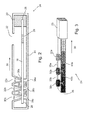
- Lateral flow capillary devices such as lateral flow capillary device 10 depicted in Figure 1 , are well known in the fields of analysis and detection and are often used for quick and simple implementation of specific binding assay of analyte in a liquid sample 12.
- Sample 12 is placed in lateral flow capillary device 10 through a reservoir 14 to contact a liquid receiving zone 16 of a bibulous capillary flow matrix 18.
- Receiving zone 16 includes a soluble labeled reagent configured to bind to the analyte which present in the sample 12.
- Sample 12 including the analyte bound to the labeled reagent migrates by capillary flow to fill all of capillary flow matrix 18 and to migrate further into liquid drain 23.
- reaction zone 20 comprises an anti-analyte that together with the analyte constitutes a specific binding pair.
- Analyte in sample 20 forms a complex with the anti analyte and is thus captured at reaction zone 20.
- an observable signal is produced at the reaction zone 20, where the intensity of the observable signal is related to the amount of analyte in the sample.
- Lateral flow capillary devices such as device 10 are extremely useful as these are simple to operate even by an unskilled person or under non-laboratory conditions and are relatively cheap to produce.
- lateral flow capillary devices such as device 10
- a sample evenly spreads in all directions until a border to capillary flow is encountered, such as an edge of the capillary flow matrix.
- sample and any analyte therein are distributed within the entire volume of the capillary flow matrix and wasted. It would be advantageous to be able to enable transport of all of a sample added to a capillary flow matrix to the vicinity of a respective reaction zone.
- reagent liquids are added serially.
- a device 10 is provided where a liquid receiving zone 16 does not include a labeled reagent.
- a sample 12 including analyte is added through reservoir 14, passes into capillary flow matrix 18 through liquid receiving zone 16 and is transported by capillary flow to drain 23.
- analyte in sample 20 forms a complex with the anti analyte located at reaction zone and is thus captured at reaction zone 20.
- a first reagent liquid containing a labeled reagent configured to bind to the analyte is added through reservoir 14, passes into capillary flow matrix 18 through liquid receiving zone 16 and is transported by capillary flow to drain 23.
- first reagent liquid passes through reaction zone 20
- labeled reagent in the first reagent liquid binds to analyte captured at the reaction zone.
- labeled reagent includes an enzyme
- a second reagent liquid containing an enzyme substrate is added through reservoir 14, passes into capillary flow matrix 18 through liquid receiving zone 16 and is transported by capillary flow to drain 23.
- the enzyme substrate therein reacts with the enzyme label, producing a strong observable signal at the reaction zone 20, where the intensity of the observable signal is related to the amount of analyte in the sample.
- EP 1044372 is taught a lateral flow capillary device where sample and reagent liquids are added at two or more adjacent positions along a capillary flow matrix that is substantially a strip of bibulous material, e.g., 8 micron pore size polyester backed nitrocellulose.
- N+1 narrow (e.g., 1 mm) spacers, impermeable hydrophobic strips of material (mylar or polyester sticky tape) are placed perpendicularly to the flow direction to define N broad (e.g., 5 mm) liquid receiving zones upstream of a reaction zone located upstream of a liquid drain.
- EP 1044372 provide the ability to perform multistep reactions using a lateral flow capillary device, but practically the teachings are severely limited by limitations imposed by the structure of the lateral flow capillary device.
- a first limitation is that the amount of liquid added to a liquid receiving zone is limited.
- the liquid is added as a drop resting on a liquid receiving zone. If the surface tension of the liquid is unsufficient, for example due to size or due to detergents in the liquid, if the capillary flow matrix is highly hydrophillic or if the lateral flow capillary device is perturbed, the drop collapses and spills from the lateral flow capillary device.
- a second limitation is that the liquids must be added simultaneously. If liquids are added non-simultaneously, a liquid added to a first liquid receiving zone flows into a second, adjacent, liquid receiving zone. When a second liquid is added to the second liquid receiving zone, the second liquid flows into a volume of the matrix from the top through dry parts of the second liquid receiving zone while the second liquid flows into the same volume laterally.
- the two liquids mix, and as discussed above, leads to unpredictable result, adversely affects duration of a given step, prevents performance of a truly sequential reaction, and affects both repeatability and accuracy of the results.
- a third limitation is that the teachings of EP 1044372 may lead to the formation of a multiple capillary paths.
- a spacer is a strip of smooth material attached using adhesive to the top surface of the matrix that has micron scale features.
- capillary paths are formed in the space between a spacer and the capillary flow matrix through which two liquids in adjacent liquid receiving zones may be mixed and as discussed above, leads to unpredictable result, adversely affects duration of a given step, prevents performance of a truly sequential reaction, and affects both repeatability and accuracy of the results.
- An additional disadvantage of the teachings of EP 1044372 is the reliance on adhesives for securing the spacers to the capillary flow matrix.
- adhesives especially non-polymerizing adhesives, are attracted by and over time migrate into bibulous materials such as nitrocellulose that are suitable for use as capillary flow matrices (see, for example, Kevin Jones; Anne Hopkins, Effct of adhesive migration in lateral flow assays; IVD Technology, September 2000).
- the adhesive securing a spacer to a capillary flow matrix of a device made in accordance with the teachings of EP 1044372 would migrate into the pores of the capillary flow matrix in the region where the liquid-liquid interface is to form.
- a hydrophobic adhesive in the matrix blocks pores or modify the capillary properties of the pores so that an interface formed between liquids is indefinite and not clear, leading to mixing of the two liquids of the interface and concomitant negative effects.
- Another disadvantage of using adhesives is the possible detachment of the spacers from the matrix during prolonged storage.
- U.S. Patent No. 4,981,786 is taught a lateral flow capillary device with two reservoirs.
- the provision of a lateral flow capillary device with two or more reservoirs allows addition of two or more suceeding liquids without mutual contamination: once a liquid has been added to a first reservoir, remnants of the liquid remain on the walls of the reservoir. Any liquid added through the same reservoir will be contaminated with the remnants.
- a first lateral flow capillary device taught in U.S. Patent No. 4,981,786 two or three distinct reservoirs are in fluid communication with a capillary flow matrix through distinct and physically separated liquid receiving zones. Located at one of the liquid receiving zones is a reaction zone including a trapping reagent.
- a liquid drain is in capillary communication with capillary flow matrix downstream from the two reservoirs.
- the use of the first lateral flow capillary device includes adding a small volume of sample through a reservoir to provide a spot of sample at the reaction zone on the capillary flow matrix and subsequently to add one or more reagents, each reagent through a different reservoir.
- two distinct reservoirs are in fluid communication with a capillary flow matrix through distinct and physically separated liquid receiving zones.
- a liquid reservoir In capillary communication with the upstream edge of the capillary flow matrix is a liquid reservoir that may be activated to release a reagent liquid that subsequently migrates downstream.
- a reaction zone is located downstream from the the two reservoirs.
- a liquid drain is in capillary communication with capillary flow matrix downstream from the reaction zone.
- both lateral flow capillary devices are taught a number of structural features to keep a capillary flow matrix in place but make only minimal contact therewith. Further, it is noted that there is little or no contact between a reservoirs and the capillary flow matrix at a respective liquid receiving zone, and if there is contact it is only light contact resulting from swelling of the capillary flow matrix upon wetting. Such features preclude the use of the lateral flow capillary devices as effective devices for multistep reactions in a manner analogous to the disclosed in EP 1044372 . When a first liquid is added to a first reservoir and simultaneously a second liquid is added to a second adjacent upstream reservoir, the first and second liquids both flow into the capillary flow matrix through a respective liquid receiving zone.
- liquid begins to leak from the capillary flow matrix at any point where an alternate capillary path exists, for example down the supporting structures on which the capillary flow matrix rests or along the laterally disposed walls that hold the capillary flow matrix in place.
- Liquid also climbs up any object contacting the upper surface of the capillary flow matrix, for example where a reservoir contacts the capillary flow matrix.
- liquid leaks away from all liquid receiving zones through any alternative capillary path, filling the lateral flow capillary device with liquid and rendering results of an experiment useless.
- a lateral flow capillary device or methods for using lateral flow capillary devices for the performance of multistep reactions in the fields of biology and medicine, particularly for diagnosis not having at least some of the disadvantages of the prior art.
- Embodiments of the present invention successfully address at least some of the shortcomings of the prior art by providing a lateral flow capillary device and a method including the use of a lateral flow capillary device allowing performance of multistep reactions.
- Embodiments of the present invention allow performance of multistep reactions such as multistep binding assays accurately and repeatably even in non-laboratory conditions and even by less skilled operators.
- a lateral flow capillary device comprising: a) a unipath bibulous capillary flow matrix having an upstream end and a downstream end defining a flow direction; b) at least two reservoirs in fluid communication with the capillary flow matrix each through at least one respective liquid receiving zone; wherein a reservoir contacts a respective liquid receiving zone through an opening constituting a hollow conduit having a rim pressing the matrix and wherein a portion of the capillary flow matrix between the two rims is an interface creation zone.
- the pressing is such that liquid-induced swelling of the matrix is constrained, that is when the matrix is wet and swells, the rims apply pressure resisting the swelling.
- the rims press the matrix when the matrix is dry. In embodiments of the present invention the rims are pressed into the matrix when the matrix is dry.
- the rims are substantially parallel to the flow direction.
- pressure applied by a rim is substantially uniform about the entire surface of the rim.
- the matrix is substantially compressible, that is does not break under pressure which leads to a reduction in volume of the matrix yet substantially retains structural integrity.
- the internal surface-area volume -1 of the matrix proximate to a rim is higher than distant from the rim.
- the matrix comprises or even essentially consists of glass fibers and/or nitrocellulose and/or porous polyethylene.
- each rim is disposed a supporting component supporting the matrix against the pressing.
- the matrix is suspended between the rims and the supporting components.
- the matrix is attached to a substantially impermeable backing.
- the impermeable backing contacts at least one supporting component supporting the impermeable backing against the pressing.
- opposite each rim is disposed a supporting component supporting the matrix against the pressing.
- the matrix is suspended between the rims and the supporting components.
- the lateral flow capillary device further comprises downstream from at least one liquid receiving zone, a reaction zone comprising at least one capturing entity (e.g., a member of a specific binding pair) configured to capture a material (e.g ., an analyte or a product of a reaction involving the analyte) flowing through the capillary flow matrix.
- a reaction zone comprising at least one capturing entity (e.g., a member of a specific binding pair) configured to capture a material (e.g ., an analyte or a product of a reaction involving the analyte) flowing through the capillary flow matrix.
- the reaction zone is in a liquid receiving zone of a reservoir.
- the lateral flow capillary device further comprises downstream from at least two liquid receiving zones, a reaction zone comprising at least one capturing entity configured to capture a material flowing through the capillary flow matrix.
- the lateral flow capillary device further comprises a liquid drain in fluid communication with the capillary flow matrix downstream from at least two of the at least two reservoirs.
- the fluid communication through the liquid receiving zones is non-capillary communication.
- the interface creation zone is a volume of matrix with a length in the flow direction, and of a width and height substantially of the capillary flow matrix, that is the interface creation zone corresponds to a cross section of the matrix with a finite length.
- the interface creation zone has a length of at least about 50%, at least about 75%, at least about 100%, even at least about 150%, and even at least about 400% of a dimension of a liquid receiving zone in the flow direction.
- liquid induced swelling of the interface creation zone is unconstrained.
- a reservoir is substantially a container.
- the device further comprises a housing containing the capillary flow matrix.
- sides of the capillary flow matrix are substantially devoid of contact with the housing.
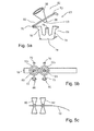
- a device useful for preparation of lateral flow capillary device comprising: a) a first component, including a reservoir with at least one wall configured to hold liquids and a lowest area, the lowest area defined by a non-capillary opening defining a hollow conduit with a rim and at least one extension protruding from an outer surface of the wall; and b) a second component, including a body with a counter-support platform at a top-end and at least one extension protruding from the body wherein an extension of the first component and a extension of the second component are configured to mutually engage so that the rim and the counter-support platform are spaced apart and substantially parallel.
- the opening is a non-capillary opening, that is of dimensions that are not conducive to capillary flow therethrough.
- the opening has a cross-sectional area of at least about 1 mm 2 , of at least about 3 mm 2 or even a cross-sectional area of at least about 7 mm 2 .
- the first component and the second component each comprise at least two extensions.
- At least one first component extension and at least one second component extension together define a hinge when engaged.
- the mutual engaging includes interlocking, for example, by snapping together.
- kits for assembly of a lateral flow capillary device comprising: a) a unipath bibulous capillary flow matrix having a thickness; and b) at least two devices as described above, wherein the distance is sufficient so that a rim contacts the matrix when the two components are engaged about the matrix.
- the distance is sufficient to clamp the matrix so as to press the rim into the matrix perpendicularly to the thickness when the two components are engaged.
- the matrix is substantially a strip of material, for example comprising glass fiber.
- the matrix is attached to a substantially impermeable backing.
- the backing is substantially planar.
- the matrix together with the backing are substantially a strip.
- the capillary flow matrix includes a reaction zone comprising at least one capturing entity (e.g., a member of a specific binding pair) configured to capture a material (e.g., an analyte or a product of a reaction involving the analyte) flowing through the capillary flow matrix.
- a capturing entity e.g., a member of a specific binding pair
- a material e.g., an analyte or a product of a reaction involving the analyte
- a method of performing a reaction comprising: a) providing a lateral flow capillary device as described above; b) adding a first amount of a first liquid to a first reservoir so that the first liquid flows into the capillary flow matrix through the respective liquid receiving zone; and c) adding a second amount of a second liquid to a second the reservoir so that a second liquid flows into the capillary flow matrix through a respective liquid receiving zone; so that a static liquid-liquid interface is formed between the first liquid and a liquid in an interface creation zone; wherein the first amount and the second amount are such that first liquid substantially remains in the first reservoir and second liquid substantially remains in the second reservoir subsequent to formation of the static interface; and wherein the interface begins to move only subsequent to exhaustion of a liquid from a reservoir. Generally, the interface moves downstream upon exhaustion of the more downstream reservoir.
- the static liquid-liquid interface is formed between the first liquid and the second liquid in the interface creation zone between the respective reservoirs to which the two liquids were added.
- the static liquid-liquid interface is formed between the first liquid and a liquid in the matrix that is located between the liquid receiving zone associated with the first reservoir and the liquid receiving zone associated with the second reservoir.
- a situation occurs, for example when using a device provided with three reservoirs and three respective liquid receiving zones where in the reservoir associated with the most downstream liquid receiving zone is added an amount of the first liquid and in the reservoir associated with the most upstream liquid receiving zone is added an amount of the second liquid so that in neither case does all the liquid enter the matrix, but in the reservoir of the middle receiving zone is added an amount of a third liquid that entirely enters the matrix.
- two interfaces are formed: one between the first liquid and the third liquid and one between the third liquid and the second liquid.
- the first liquid and the second liquid are substantially identical, e.g ., both are analyte containing sample.
- the first liquid and the second liquid are substantially different, for example one is an analyte containing sample and one is a reagent liquid (e.g., a solution including signal producing label).
- the first amount and the second amount are substantially different. In embodiments of the present invention, the first amount and the second amount are substantially equal.
- adding of the second amount is subsequent to the adding of the first amount. In embodiments of the present invention, adding of the first amount and of the second amount is substantially simultaneous.
- a method of performing a reaction comprising: a) providing a lateral flow capillary device as described above including: i) on the capillary flow matrix, a first liquid receiving zone in fluid communication with a first reservoir; ii) on the capillary flow matrix upstream of the first liquid receiving zone, a second liquid receiving zone in fluid communication with a second reservoir; iii) a first reagent disposed at a location inside the first reservoir and/or in the capillary flow matrix in proximity to the first liquid receiving zone or downstream therefrom; iv) a second reagent disposed at a location inside the second reservoir and/or in the capillary flow matrix in proximity to the second liquid receiving zone; b) adding a first amount of a first liquid to the first reservoir so that the first liquid flows into the capillary flow matrix through the first liquid receiving zone to contact the first reagent; c) adding a second amount of a second liquid to the second reservoir so that the second liquid flows into the
- the first liquid and the second liquid are substantially identical, e.g., both are analyte containing sample.
- the first liquid and the second liquid are substantially different, for example one is an analyte containing sample and one is a reagent liquid (e.g., a solution including signal producing label).
- the first amount and the second amount are substantially different. In embodiments of the present invention, the first amount and the second amount are substantially equal.
- downstream of the first liquid receiving zone on the capillary flow matrix is a reaction zone comprising at least one capturing entity configured to capture a material flowing through the capillary flow matrix.
- adding of the second amount and the adding of the first amount is sequential. In embodiments of the present invention, adding of the first amount and of the second amount is substantially simultaneous.
- the present invention is of a lateral flow capillary device and methods of using the lateral flow capillary device.
- the present invention allows performance of effective and repeatable multistep reactions such as multistep specific binding assays for example for serological testing.
- the embodiments are directed to an analytical method for detecting an analyte that is a biomarker such as an antigen, antibody, metabolite, toxicant or other detectable material from human or other living source such as blood, urine, tissue, or from a non-living source such as an environmental source like water, soil or sewage.
- a biomarker such as an antigen, antibody, metabolite, toxicant or other detectable material from human or other living source such as blood, urine, tissue, or from a non-living source such as an environmental source like water, soil or sewage.
- the embodiments are directed to binding the analyte to an anti-analyte immobilized at a reaction zone on the capillary flow matrix which together with the analyte constitutes a specific binding pair such as an antibody, antigen, DNA or other specific binding pair (sbp) member and that the bound analyte is then detected directly or by a labeled reagent producing a detectable signal or that produces a detectable signal after being exposed to a third reagent which reacts with the labeled reagent and produces a detectable signal that can be visualized or measured. by reading instrument.
- a specific binding pair such as an antibody, antigen, DNA or other specific binding pair (sbp) member
- method refers to manners, means, techniques and procedures for accomplishing a given task including, but not limited to, those manners, means, techniques and procedures either known to, or readily developed from known manners, means, techniques and procedures by practitioners of the relevant arts.
- Implementation of the methods of the present invention involves performing or completing selected tasks or steps manually, automatically, or a combination thereof.
- analyte refers to the compound or composition to be detected or quantitatively analyzed and which has at least one epitope or binding site.
- An analyte can be any substance for which there exist a naturally occurring analyte specific binding member or for which an analyte-specific binding member can be prepared. e.g., carbohydrate and lectin, hormone and receptor, complementary nucleic acids, and the like.
- possible analytes include virtually any compound, composition, aggregation, or other substance which may be immunological detected. That is, the analyte, or portion thereof, will be antigenic or haptenic having at least one determinant site, or will be a member of a naturally occurring binding pair.
- Analytes include, but are not limited to, toxins, organic compounds, proteins, peptides, microorganisms, bacteria, viruses, amino acids, nucleic acids, carbohydrates, hormones, steroids, vitamins, drugs (including those administered for therapeutic purposes as well as those administered for illicit purposes), pollutants, pesticides, and metabolites of or antibodies to any of the above substances.
- an analyte is found in a "sample”and the teachings of the present invention are applied to the sample to determine the presence of or an amount of analyte present in a sample.
- sample refers to anything which may contain an analyte for which an analyte assay is desired.
- the sample may be a biological sample, such as a biological fluid or a biological tissue.
- biological fluids include urine, blood, plasma, serum, saliva, semen, stool, sputum, cerebral spinal fluid, tears, mucus, amniotic fluid or the like.
- Biological tissues are aggregate of cells, usually of a particular kind together with their intercellular substance that form one of the structural materials of a human, animal, plant, bacterial, fungal or viral structure, including connective, epithelium, muscle and nerve tissues. Examples of biological tissues also include organs, tumors, lymph nodes, arteries and individual cell(s).
- a solid material suspected of containing the analyte can be used as the test sample once it is modified to form a liquid medium or to release the - analyte.
- Pretreatment may involve preparing plasma from blood, diluting viscous fluids, and the like. Methods of treatment can involve filtration, distillation, separation, concentration, inactivation of interfering components, and the addition of reagents. Besides physiological fluids, other samples can be used such as water, food products, soil extracts, and the like for the performance of industrial, environmental, or food production assays as well as diagnostic assays. The selection and pretreatment of biological, industrial, and environmental samples prior to testing is well known in the art and need not be described further.
- the term "specifically binds” refers to the binding specificity of a "Specific binding pair member” which is a member of a specific binding pair, i.e., two different molecules wherein one of the molecules specifically binds with the second molecule through chemical or physical means.
- the two molecules are related in the sense that their binding with each other is such that they are capable of distinguishing their binding partner from other assay constituents having similar characteristics.
- the members of the specific binding pair are referred to as ligand and receptor (anti ligand), sbp member and sbp partner, and the like.
- a molecule may also be a sbp member for an aggregation of molecules; for example an antibody raised against an immune complex of a second antibody and its corresponding antigen may be considered to be an sbp member for the immune complex.
- specific binding pairs include, as examples without limitation, biotin and avidin, carbohydrates and lectins, complementary nucleotide sequences, complementary peptide sequences, effector and receptor molecules, enzyme cofactors and enzymes, enzyme inhibitors and enzymes, a peptide sequence and an antibody specific for the sequence or the entire protein, polymeric acids and bases, dyes and protein binders, peptides and specific protein binders (e.g., ribonuclease, S-peptide and ribonuclease S-protein), metals and their chelators, and the like.
- specific binding pairs can include members that are analogs of the original specific binding member, for example an analyte-analog or a specific binding member made by recombinant techniques or molecular engineering.
- a sbp member is analogous to another sbp member if they are both capable of binding to another identical complementary sbp member.
- a sbp member may, for example, be either a ligand or a receptor that has been modified by the replacement of at least one hydrogen atom by a group to provide, for example, a labeled ligand or labeled receptor.
- the sbp members can be analogous to or complementary to the analyte or to an sbp member that is complementary to the analyte. If the specific binding member is an immunoreactant it can be, for example, an antibody, antigen, hapten, or complex thereof.
- an antibody can be a monoclonal or polyclonal antibody, a recombinant protein or antibody, a chimeric antibody, a mixture(s) or fragment (s) thereof, as well as a mixture of an antibody and other specific binding members.
- the details of the preparation of such antibodies and their suitability for use as specific binding members are known to those skilled in the art.
- Label reagent refers to a substance comprising a detectable label attached with a specific binding member.
- the attachment may be covalent or non-covalent binding, but the method of attachment is not critical to the present invention.
- the label allows the label reagent to produce a detectable signal that is related to the presence of analyte in the sample.
- the specific binding member component of the label reagent is selected to directly bind to the analyte or to indirectly bind the analyte by means of an ancillary specific binding member, which is described in greater detail hereinafter.
- the specific binding member may be labeled before or during, the performance of the assay by means of a suitable attachment method.
- Label refers to any substance which is capable of producing a signal that is detectable by visual or instrumental means.
- Various labels suitable for use in the present invention include labels which produce signals through either chemical or physical means. Such labels can include enzymes, fluorescent compounds, chemiluminescent compounds, and radioactive labels.
- Other suitable labels include particulate labels such as colloidal metallic particles such as gold, colloidal non-metallic particles such as selenium, dyed or colored particles such as a dyed plastic or a stained microorganism, organic polymer latex particles and liposoms, colored beads, polymer microcapsules, sacs, erythrocytes, erythrocyte ghosts, or other vesicles containing directly visible substances, and the like.
- a visually detectable label is used as the label component of the label reagent, thereby providing for the direct visual or instrumental readout of the presence or amount of the analyte in the test sample without the need for additional signal producing, components at the detection sites.
- a particular label is not critical to the present invention, but the label will be capable of generating a detectable signal either by itself, or be instrumentally detectable, or be detectable in conjunction with one or more additional signal producing components.
- label reagents can be formed by varying either the label or the specific binding member component of the label reagent; it will be appreciated by one skilled in the art that the choice involves consideration of the analyte to be detected and the desired means of detection. As discussed below, a label may also be incorporated used in a control system for the assay.
- one or more signal producing components can be reacted with the label to generate a detectable signal.
- the label is an enzyme
- amplification of the detectable signal is obtained by reacting the enzyme with one or more substrates or additional enzymes and substrates to produce a detectable reaction product.
- Labeled enzymes used in the field include, for example, Alkaline phosphatase, Horseradish peroxidase, Glucose oxidase and Urease.
- the label in an alternative signal producing system, can be a fluorescent compound where no enzymatic manipulation of the label is required to produce the detectable signal.
- Fluorescent molecules include, for example, fluorescein, phycobiliprotein, rhodamine and their derivatives and analogs are suitable for use as labels in such a system.
- dyes for staining biological materials such as proteins, carbohydrates, nucleic acids, and whole organisms
- biological materials such as proteins, carbohydrates, nucleic acids, and whole organisms
- certain dyes stain particular materials preferentially based on compatible chemistries of dye and ligand.
- Coomassie Blue and Methylene Blue for proteins for proteins, periodic acid-Schiffs reagent for carbohydrates, Crystal Violet, SafraninO, and Trypan Blue for whole cell stains
- Ethidium bromide and Acridine Orange for staining biological materials, such as proteins, carbohydrates, nucleic acids, and whole organisms.
- “Signal producing component” refers to any substance capable of reacting directly or indirectly with the labeled reagent to produce signal that is detectable by visual or instrumental mean.
- the component may be substrate catalyzed by the labeled enzyme or dyes that may react chemically with the label reagent (dsDNA/ Acridine Orange), enzymes substrate such as: BCIP/NBT; Azonaphtol phosphate; 3-AEC; 4-chloronaphyhol; tetrazolium salt/PMS; Urea/PH indicators.
- a capillary flow matrix includes at least one reaction zone.
- a reaction zone is a region or volume of the matrix comprising at least one capturing entity configured to capture a material flowing through the capillary flow matrix in defined regions for conducting the assay reaction including a test line and a control line.
- a "test line” Is the region in the reaction zone, in which the analytical assay is performed.
- the region comprises specific binding pair (sbp) member which is immobilized to the matrix of the capillary path.
- the sbp member can be an antibody or antigen nucleic acid or modifications of the above. It may by proteins like avidin and its derivatives or saccharides such has lectins.
- test line which are part of binding pair being capable of binding directly or indirectly the analyte of interest.
- test line may be in the reaction zone each of a distinct specific binding pair for different analytes.
- a "control line" Is the region in the reaction zone, in which a reaction for confirming the validity of the assay is performed; the control line may also be a calibration line or lines for correction of the assay signals (results) obtained in the test line.
- the control line comprise of immobilized spb member with binding abilities to one or more of the reagents participating in the reaction or compounds existing in the sample.
- a capillary flow matrix is bibulous, that is comprises a bibulous, porous or other cavity shaped material allowing capillary transport of liquids therethrough, that is the pores define a continuous system of capillary flow channels.
- capillary transport requires a continuous path of pores of less than about 2 mm in size, generally in the range of 0.05 microns to 100 microns.
- a suitable capillary flow matrix is substantially compressible, that is to say, retains structural integrity and does not break under applied pressure which leads to a reduction in volume, for example pressure applied by the reservoir rims.
- pressure applied to a capillary flow matrix perpendicularly by a reservoir rim compresses the capillary flow matrix to substantially same extent through the entire height of the capillary flow matrix.
- a matrix is thick enough and soft enough so that compression caused by applied pressure is local to the pressing.
- pressure applied by a rim to a capillary flow matrix substantially compresses the matrix and reduces the internal surface-area volume -1 to a depth of no more than 40% of the thickness.
- Bibulous material include but are not limited to materials composed of glass fiber paper or derivatized glass fiber paper,cellulose and its derivatives, nylons, PVDF, polysulfones, PTFE and polypropylene, paper and derivatized paper, see Eric Jallerat and Volkmar Thom, "Filter membranes and bioseparation equipment and supplies” by IVD Technology (2004 ) or catalogues of manufacturers such as Millipor Corp. (Bedford, Massachusetts, USA), Watman Inc. (New Jersey, USA) or Ahlstrom Corp. (Helsinki, Finland).
- the bibulous member consists of a series of fibers drawn together in parallel to form an open wick with some mechanical integrity due to bonding between the fibers, with the space between the fibers acting to form channels, which draw up liquid.
- Suitable fibers include polyester, polyamides such as nylons, and bicomponent fibers such as polyethylene/polyester, nylon/polyester and the like.
- Bicomponent polyethylene/polyester fibers typically comprise a polyester central core with an external sheath of polyethylene.
- Inherently hydrophobic fibers such as polypropylenes can also be used provided they are water wettable or, if necessary, are rendered water wettable by other components such as surfactants or hydrophilic polymers. In principle any wettable fiber is suitable.
- Fibers can be formed into a bibulous member by a variety of processes, such as annealing to partially melt the surface/sheath region and cause interpenetration of the polymer chains, which set on cooling see.
- adhesives such as latex adhesives, may be used.
- Capillary matrices of embodiments of the invention are of various forms including but not limited to sheets, columns, membranes, and compressed fibers.
- Suitable materials include but are not limited to porous materials and fibrous materials, including woven, rationally oriented and randomly oriented fibrous materials.
- Suitable materials include polymeric materials such as porous polymers including porous polyethylene, polypropylene, polytetrafluoroethylene (PTFE), ethylene vinyl acetate (EVA), polyether sulfone (PS), thermoplastic urethane (TPU), polyamide (e.g., Nylon 6) and copolymers thereof such as porous polymers manufactured by the Porex Corporation, Fairburn GA, USA.
- Suitable materials include fibrous materials such as cellulose, cellulosic materials, cellulose derivatives, glass fibers, paper, filter paper, chromatographic paper, synthetic or modified naturally occurring polymers, such as nitrocellulose, cellulose acetate and cotton.
- a bibulous capillary flow matrix of the present invention is a uniform structure such as strip of paper or a combination of several materials comprisng a unipath structure.
- a capillary flow matrix of the present invention is attached to a substantially impermeable backing material, for example as is known in the field of thin-layer chromatography where porous fibrous matter is bound to a solid impermeable backing.
- a backing is of the same dimensions as the capillary flow matrix: when smaller or larger then the interface between the matrix and backing may produce a capillary path parallel to the capillary path defined by the capillary flow matrix.
- Suitable materials from which to form a backing include but are not limited to polyethylene, polypropylene, poly(4-methylbutene), polystyrene, polymethacrylate, poly(ethylene terephthalate), nylon, poly(vinyl butyrate), glass, ceramics, metals, polyurethane, neoprene, latex and silicone rubber.
- a material exceptionally suitable for preparing a capillary flow matrix of the present invention is glass fiber especially plastic backed glass fiber, including glass fiber derivative such as glass fiber/cellulose/polyester matrices.
- Glass fiber membranes are relatively thick, (typically up to 2mm), have pore sizes of 1-40 micron and a relatively high water flow rate (when compared to typical nitrocellulose matrix) allowing large sample and reagent flow through.
- An additional advantage of glass fiber, as noted above, is that glass fiber is relatively thick, soft and compressible so that when pressure is applied in accordance with the teachings of the present invention, compression is local to the point of pressure.
- a material exceptionaly suitable for preparing a capillary flow matrix of the present invention is nitrocellulose, especially plastic backed nitrocellulose, especially having a pore size of between 0.45 and 15 micron.
- a material exceptionaly suitable for preparing a capillary flow matrix of the present invention is porous polyethylene, especially having a pore size of between 0.2 and 20 micron, preferably between 1 and 12 micron, available from the Porex Corporation, Fairburn GA, USA.
- a lateral flow capillary device of the present invention is a manually operated lateral flow capillary device.
- the length of a capillary flow matrix be convenient for manual use and storage of a lateral flow capillary device, which is to say generally but not necessarily at least about 1 cm, and generally not greater than about 30 cm, not greater than about 15 cm and even not greater than about 10 cm.
- the width of a capillary flow matrix be sufficiently narrow to allow concentration of a material producing a signal in a small area to increase the contrast of a signal produced and reduce the liquid capacity of the capillary flow matrix, but also sufficiently wide to allow simple observation of the signal by a user, which is to say generally but not necessarily between about 1 mm and 20 mm.
- the capillary flow matrix be relatively thick to allow a high liquid capacity and flow rate and also ensure that the pressure applied by the rims compresses the matrix only locally.
- the capillary flow matrix is up to about 2 mm thick, up to about 1 mm thick, and preferably between about 0.05 and about 0.5 mm thick.
- a capillary flow matrix is in capillary communication with a liquid drain.
- a liquid drain is generally a component made of a bibulous material and having a liquid absorbing capacity that is significantly larger than that of a respective capillary flow matrix.
- a liquid drain is integrally formed with a respective capillary flow matrix.
- a liquid drain constitutes at least one component distinct from a respective capillary flow matrix.
- a liquid drain is of a shape or of material that allows a faster rate of capillary movement than through a respective capillary flow matrix. Suitable materials from which to fashion a drain are described, for example, in U.S. Patent No. 4,632, 901 , such as, for example, fibrous materials such as cellulose acetate fibers, cellulose or cellulose derivatives, polyester, or polyolefins.
- reservoirs are of any suitable shape or size.
- a joint between two faces may define a capillary channel, in embodiments, the inner surface of a reservoir in contact with or immediate proximity with a liquid receiving zone is continuous, for example circular, oval or otherwise curved.
- the volume of a given reservoir is determined by many factors and the exact implementation of a respective lateral flow capillary device. That said, a typical reservoir of a lateral flow capillary device of the present invention generally has a capacity of at least about 5 microliter, at least about 20 microliter or even at least about 50 microliter and generally no greater than about 5000 microliter, no greater than about 1000 microliter and even no greater than about 300 microliter.
- Lateral flow capillary device 24 includes a unipath bibulous capillary flow matrix 18 having an upstream end 26 and a downstream end 28 defining a flow direction 30.
- Capillary flow matrix 18 of lateral flow capillary device 24 is substantially porous membrane of enforced nitrocellulose devoid of a backing layer.
- a downstream reservoir 32a, a middle reservoir 32b and an upstream reservoir 32c constituting open-topped containers are in non-capillary fluid communication (to preserve the unipath of lateral flow capillary device 24 ) with capillary flow matrix 18 each through a respective liquid receiving zone 34a, 34b and 34c.
- the distance between the edges of liquid receiving zones 34a, 34b and 34c is at least 50% of the dimension of such a liquid receiving zone in flow direction 30, although in embodiments is substantially larger.
- the capillary matrix between any two receiving zones is defined as an interface creation zone.
- Interface creation zone 35a is found between liquid receiving zones 34a and 34b.
- Interface creation zone 35b is found between liquid receiving zones 34b and 34c.
- Each reservoir 32a, 32b or 32c contacts a respective liquid receiving zone 34a, 34b and 34c through an opening at the bottom of the reservoir constituting a hollow conduit having a rim 36a, 36b and 36c.
- each rim 36a, 36b and 36c are disposed supporting components 38a, 38b and 38c respectively.
- Rims 36a, 36b and 36c press into capillary flow matrix 18, even when capillary flow matrix is dry while supporting components 38a, 38b and 38c support capillary flow matrix 18 against the pressing so that capillary flow matrix 18 is substantially suspended between rims 36a, 36b and 36c and supporting components 38a, 38b and 38c.
- Rims 36a, 36b and 36c and the upper surfaces of supporting components 38a, 38b and 38c are substantially parallel to flow direction 30, ensuring that pressure applied by a rim 36a, 36b or 36c is substantially uniform about the entire surface of that rim.
- the internal surface-area per unit volume of matrix 18 proximate to a rim 36a, 36b or 36c is higher than distant from a rim 36a, 36b or 36c. The presumed significance of this difference is discussed hereinbelow.
- the matrix material in interface creation zones 35a and 35b is unconstrained for liquid-induced swelling.
- Capillary flow matrix 18 is provided with a reaction zone 20 including at least one capturing entity configured to capture a material such as an analyte or a product of a reaction involving the analyte flowing through capillary flow matrix 18 downstream from liquid receiving zones 34a, 34b and 34c.
- capillary flow matrix 18 is in fluid communication with liquid drain 23.
- Capillary flow matrix 18 and liquid drain 23 are substantially contained within a housing 40 such that all sides of capillary flow matrix 18 are substantially devoid of contact with housing 40.
- an observation window 22 which in embodiments is simply a gap through housing 40.
- a first amount of a first liquid for example sample containing analyte is placed in downstream reservoir 32a, flows into capillary flow matrix 18 through liquid receiving zone 34a and spreads both upstream and downstream from liquid receiving zone 34a.
- a second amount of a second liquid for example labeled reagent, is placed in middle reservoir 32b, flows into capillary flow matrix 18 through liquid receiving zone 34b and spreads both upstream and downstream from liquid receiving zone 34b.
- a third amount of a third liquid, for example signal producing component is placed in upstream reservoir 32c, flows into capillary flow matrix 18 through liquid receiving zone 34c and spreads both upstream and downstream from liquid receiving zone 34c.
- the third liquid flows upstream until all of capillary matrix 18 upstream of liquid receiving zone 34c becomes saturated with third liquid.
- Third liquid flows downstream from liquid receiving zone 34c until encountering second liquid flowing upstream from liquid receiving zone 34b forming a static interface 42b (see Figure 3 ) somewhere in interface creation zone 35b wherethrough there is substantially no mixing of liquids.
- Second liquid flows downstream from liquid receiving zone 34b until encountering first liquid flowing upstream from liquid receiving zone 34a forming a static interface 42a somewhere in interface creation zone 35a wherethrough there is substantially no mixing of liquids.
- interface 42a Once interface 42a is formed, and assuming that the amount of first and second liquids added is sufficient so as not to be entirely absorbed into capillary flow matrix 18, a standing column of second liquid is formed in middle reservoir 32b, the second liquid prevented from flowing downstream by pressure applied by first liquid in downstream reservoir 32a.
- First liquid from downstream reservoir 32a drains down through liquid receiving zone 34a and flows downstream in flow direction 30 past reaction zone 20 on which sbp member (receptor) is immobilized. Analyte if present in the sample is captured by the sbp member while liquid is absorbed into liquid drain 23.
- the first liquid/second liquid interface begins to move downstream in flow direction 30 as second liquid from middle reservoir 32b drains down through liquid receiving zone 34b and flows downstream in flow direction 30. During this time, the second liquid/third liquid interface remains static. Labeled reagent present in the second liquid binds to complex formed at reaction zone 20, if present.
- the second liquid/third liquid interface begins to move downstream in flow direction 30 as third liquid from upstream reservoir 32c drains down through liquid receiving zone 34c and flows downstream in flow direction 30.
- Signal producing component present in the third liquid reacts with the labeled reagent bound to complex, to generate an observable signal
- 4,981,786 leakage occurs along support components on which the capillary flow matrix rests, along laterally disposed support components that hold the capillary flow in place and up the contact points of reservoirs with the capillary flow matrix, producing a flow of liquid on the top surface of the capillary flow matrix.
- the teachings of the present invention allow performance of multistep reactions using a lateral flow capillary device where each step is performed with a relatively precise amount of reagent for a relatively preciseduration. Since leakage is prevented and since the duration of a reaction step is accurately determined by the volume of the different liquids added, many different multistep experiments can be performed to yield repeatable results. Further, as the volume of liquid is the primary determinant of duration of a given step, the duration of a given step is easily modified if required, allowing performance of kinetic experiments.
- Water potential ⁇ of the liquid is the potential energy of water in a given volume (mass) and determines flow direction from a volume of a higher water potential to a volume with a lower water potential.
- the total water potential ⁇ of a volume of water is the sum of four component potentials: gravitational ( ⁇ g), matrix ( ⁇ m), osmotic ( ⁇ s), and pressure ( ⁇ p).
- Gravitational potential depends on the position of the water in a gravitational field.
- Matrix potential depends on the adsorptive forces binding water to a matrix.
- Osmotic potential depends on the concentration of dissolved substance in the water (e.g., a solution having a high salt concentration has a negative value).
- Pressure potential depends on the hydrostatic or pneumatic pressure on the water.
- Matrix potential is affected by both matrix and liquid properties.
- Matrix potential is affected by the attraction of the liquid to the matrix (hydrophilicity) and the surface area of the cavities in the matrix.
- the force acting on a liquid inside the capillary flow matrix includes the force applied by a single column of liquid in a reservoir contributing to ⁇ p.
- the attraction of the liquid molecules to the internal surfaces of the capillary flow matrix ( ⁇ m) are sufficient to prevent leakage of liquid along alternate capillary paths formed, for example, where some physical object contacts the capillary flow matrix.
- the force acting on a liquid inside the capillary flow matrix includes the force applied by two standing columns of liquid in two reservoirs both contributing to ⁇ p.
- ⁇ m that is a measure of the attraction between the liquid molecules and the internal surfaces of the capillary flow matrix are insufficient to prevent leakage of liquid along alternate capillary flow paths.
- contact points are eliminated except at the rims of the reservoirs and, if present, at the oppositely disposed supporting components, which are pressed into the capillary flow matrix.
- the pressing of these components locally compresses the matrix and the pores therein, reducing the volume of the matrix proximal to these components but not changing the total internal surface area.
- Such pressing increases the capillary flow matrix / liquid interaction energy per unit volume in the vicinity of the components and therefore increases ⁇ m. This increased energy is apparently sufficient to compensate for the increased force applied by the two columns of liquid.
- pressing of the matrix increases the binding energy in the vicinity of the contact points with the rims or supporting components, reducing the tendency to leak across the alternative capillary flow path formed at the contact point.
- a given interface creating zone is relatively wide relative to flanking liquid receiving zones.
- An advantage of such embodiments is that the size of the interface creating zone means that liquid added to one of the liquid receiving zones requires a significant period of time to travel through the interface creating zone before arriving at the neighboring liquid receiving zone. This allows addition of liquids to different reservoirs to be sequential and to be performed under more difficult (e.g., non laboratory) conditions, and even by less skilled operators.
- An additional advantage of a relatively wide interface creation zone is to compensate for different absorption rates of different liquids added. For example, the rate of entry of a viscous or hydrophobic liquid is relatively slow.
- a relatively wide interface creation zone prevents faster matrix entering liquids from travelling to a liquid receiving zone where a viscous or hydrophobic liquid is added, allowing the viscous or hydrophobic liquid to enter the matrix and create a sharp, well-defined liquid-liquid interface.
- capillary flow matrices swell upon contact with water.
- the swelling may be inhomogenous and cracks may form in the matrix, locally modifying the capillary properties of the matrix. If the interface forms in a volume where the capillary properties are changed, the interface formed between liquids may be indefinite and not clear, leading to mixing of the two liquids of the interface and concomitant negative effects.
- liquid induced swelling of the interface creation zone is unconstrained.
- the first liquid and second liquid are added substantially simultaneously to a respective reservoir.
- the first liquid and second liquid are added sequentially.
- the order in which the liquids is added it is of little significance, as long as a subsequent liquid is added to a respective reservoir before an earlier added liquid migrates into the liquid receiving zone of the reservoir of the subsequently added liquid.
- the method of the present invention as described above is not directed to the transport of liquids through a capillary flow matrix, but rather allows the performance of multistep reactions especially multistep specific binding assays, where each of the two liquids initiates and performs a different step of a multistep reaction, for example transport of a reagent.
- the volume of any given liquid determines to a large degree the duration of a respective step.
- reaction zone 20 comprisies at least one capturing entity (e.g., a member of a specific binding pair) configured to capture a material (e.g ., an analyte or a product of a reaction involving the analyte) flowing through the capillary flow matrix.
- the reaction zone is in a liquid receiving zone of a respective reservoir.
- a lateral flow capillary device is provided with one or more reagents pre-loaded onto the capillary flow matrix.
- reagents pre-loaded onto the capillary flow matrix.
- preloading of reagents is known in the art of lateral flow capillary devices, for example by drying reagents onto the matrix, for example by freeze drying, spray drying, dispensing and air drying.
- a reagent is loaded onto the capillary flow matrix in such a way that a liquid added through a specific reservoir will interact with the reagent.
- at least one pre-loaded reagent is configured to react with an added analyte to produce a reaction product that is subsequently transported downstream along the capillary flow matrix.
- at least one pre-loaded reagent is configured to be solubilized by an added liquid and to be subsequently transported downstream along the capillary flow matrix.
- a preloaded reagent is located substantially in a liquid recieving zone.
- a preloaded reagent is located in the vicinity of a liquid receiving zone, specifically in an adjacent interface creation zone.
- Embodiments of the present invention allow material to be preloaded both upstream and downstream of a given liquid receiving zone, allowing material to be preloaded in a relatively large region of matrix using simple methods, for example by spray-drying.
- material preloaded downstream from the most downstream liquid receiving zone is preloaded at any distance from the liquid receiving zone, generally (but not necessarily) between the liquid receiving zone and a reaction zone.
- Material preloaded in the vicinity of a most upstream liquid receiving zone is generally loaded downstream from the liquid receiving zone so that all the material will be used when liquid is introduced into the most upstream liquid receiving zone.
- Other preloaded material is generally preloaded either in the liquid receiving zone or somewhat upstream or somewhat downstream from the liquid receiving zone, for example up to about 30% of the length of the adjacent interface creation zone.
- the matrix is attached to a substantially impermeable backing material to avoid leakage of liquids from the capillary flow matrix.
- Figure 4 is depicted an embodiment of a lateral flow capillary device of the present invention, 46.
- capillary flow matrix 18 is attached to a substantially impermeable backing 48. Together, capillary flow matrix 18 and impermeable backing 48 constitute a strip that rests on plateau 50, where backing 48 contacts plateau 50.
- lateral flow capillary device 46 is provided with four reservoirs 32a, 32b, 32c and 32d with respective rims 36a, 36b, 36c and 36d that press the upper surface of capillary flow matrix 18. Plateau 50 is disposed opposite each rim 36 of each reservoir 32 and thus constitutes a supporting component supporting matrix 18 against the pressing of rims 36.
- Lateral flow capillary device 46 is configured for the simple performance of four-step reactions.
- a first reagent 52 is preloaded in liquid receiving zone 34a, first reagent 52 being a nutrient configured to cause living cells contacting first reagent 52 to express certain proteins on external membranes.
- a second reagent 54 is preloaded to an area of capillary matrix 18 between liquid receiving zones 34b and 34c, second reagent 54 being a toxin.
- a third reagent 56 is preloaded to liquid receiving zone 34d, third reagent 56 being an indicator that binds to the certain protein.
- Reaction zone 20 includes a capture entity configured to immobilize cells.
- lateral flow capillary device 46 is substantially similar to the use of lateral flow capillary device 24 as described above and is clear to one skilled in the art upon perusal of the description herein.
- a first liquid sample, including living cells is placed in reservoir 32a, a second liquid placed in reservoir 32b, a third liquid placed in reservoir 32c and a fourth liquid placed in reservoir 32d, sequentially or simultaneously.
- Three liquid interfaces are formed in the interface creation zones 35a, 35b, 35c, the interface 42a, 42b, 42c.
- Standing columns of liquid are produced in reservoirs 32b, 32c and 32d.
- second liquid in reservoir 32b begins to flow through capillary flow matrix 18, transporting waste and other non-bound material away from reaction zone 20 towards liquid drain 23.
- third liquid in reservoir 32d begins to flow through capillary flow matrix 18, carrying the second reagent 54.
- Second reagent 54 is transported to reaction zone 20, killing immobilized cells.
- third liquid in reservoir 32c When third liquid in reservoir 32c is exhausted, fourth liquid in reservoir 32d begins to flow through capillary flow matrix 18, carrying the third reagent 56. Third reagent 56 is transported to reaction zone 20, producing a visible signal on cells that expressed the certain proteins on external membranes.
- nucleic acid absorption particles are attached to a reaction zone of a capillary flow matrix and a sample containing nucleic acids is added under binding conditions resulting in concentration of nucleic acid from the sample.
- concentration step is followed by washing, elution and/or analysis steps.
- Suitable methods include methods that employ one or more techniques including but not limited to welding, casting, embossing, etching, free-form manufacture, injection-molding, microetching, micromachining, microplating, molding, spin coating, lithography or photo-lithography.
- a device and a kit are provided allowing the simple and cheap preparation of a custom lateral flow capillary device in accordance with the teachings of the present invention.
- a device 60 of the present invention useful for the preparation of lateral flow capillary device is depicted in Figure 5A .
- Device 60 comprises a first component 62 and a second component 64, connected through protruding extensions 66 and 68 by a hinge 70.
- First component 62 includes a reservoir 32 having one wall configured to hold liquids.
- the lowest area of reservoir 32 is a non-capillary opening 63 defining a hollow conduit with a rim 36.
- rim 36 is relatively wide, at least about 0.5 mm or even at least about 1 mm.
- rim 36 is substantially planar.
- non-capillary opening 63 is relatively large, in embodiments having a cross-sectional area of at least about 1 mm 2 , of at least about 3 mm 2 or even of at least about 7 mm 2 .
- Opposite extension 66 and also protruding from reservoir 32 is protrusion 72.
- Second component 64 includes a body 74 with a counter support platform 76 at the top end of body 74. Opposite extension 68 and also protruding from body 74 is protrusion 78.
- Protrusions 72 and 78 are configured to mutually engage, interlocking (for example by “snapping together") so as to hold rim 36 and counter support platform 76 substantially parallel spaced apart at some predetermined distance.
- first component 62 is provided with two extensions 66 and 72 to engage two extensions 68 and 78 of second component 64.
- a first component and/or a second component are provided with only one extension, or with more than two such extensions each.
- extensions 66 and 68 are formed as one piece to define hinge 70.
- extensions are configured to be reversibly or irreversibly engaged, when engaged defining a hinge.
- extensions are configured to be reversibly or irreversibly engaged, when engaged not defining a hinge.
- a device of the present invention such as device 60 in the framework of a kit of the present invention
- a kit of the present invention comprising two devices 60 and a strip of plastic backed glass fiber as a bibulous capillary flow matrix 18 is depicted in an assembled state, together constituting an embodiment of the device of the present invention.
- capillary flow matrix 18 of an appropriate thickness is cut to size and two devices 60 are closed over an appropriate area of capillary flow matrix 18.
- the thickness of capillary flow matrix 18 and the design of devices 60 is such that, when extensions 72 and 78 are mutually engaged, capillary flow matrix 18 is clamped between rim 36 and counter support platform 76 In such a state, non-capillary openings 63 defines a liquid receiving zone. Further, rim 36 presses into capillary flow matrix 18, in accordance with the teachings of the present invention.
- a lateral flow capillary device including a lateral flow capillary device of the present invention is easily custom built and modified with the use of embodiments of devices of the present invention and embodiments of kits of the present invention.
- application of desired reagents to define a reaction zone or to preload a reagent onto a capillary matrix is simple to achieve.
- a lateral flow capillary device substantially as described above is used including: a first liquid receiving zone on the capillary flow matrix in fluid communication with a first reservoir, a second liquid receiving zone on the capillary flow matrix in fluid communication with a second reservoir upstream of the first reservoir, a first reagent preloaded inside the first reservoir and/or at a location on the capillary flow matrix in proximity to the first liquid receiving zone or downstream therefrom; a second reagent preloaded at a location inside the second reservoir and/or on the capillary flow matrix in proximity to the second liquid receiving zone.
- a first amount of a liquid (e.g., the sample) is added to the first reservoir so that the liquid flows into the capillary flow matrix through the first liquid receiving zone to contact the first reagent, e.g., to react with the first reagent or to solublize the first reagent.
- a second amount of a liquid (either the same or different) is added to the second reservoir so that the liquid flows into the capillary flow matrix through the second liquid receiving zone to contact the second reagent.
- the second amount of liquid is added before, after or substantially simultaneously with the addition of the first amount of liquid.
- a static interface is formed between the liquid contacting the first reagent and the liquid contacting the second reagent in the interface creation zone between the two liquid receiving zones.
- the interface moves only subsequent to exhaustion of liquid from the first reservoir.
- liquid added to the first reservoir is the same as that added to the second reservoir, only one liquid is added (for example through a single port in communication with a number of liquid receiving zones) as in a single reservoir lateral flow capillary device but performs a multistep reaction with all the advantages thereof. This reduces the number of steps required to perfom an otherwise complex multistep reaction.
- a lateral flow capillary device such as lateral flow capillary device 80 depicted in Figures 6A , 6B and 6C was prepared.
- a lower housing part 82 and an upper housing part 84 configured to snap together to form a closed shell holding a capillary flow matrix 18 and two liquid drains 86 and 88 were fashioned by injection molding of ABS (acrylonitrile-butadiene-styrene copolymer) plastic.
- Lower housing 82 was substantially a lidless box having a bottom with a plateau portion 50 and a recessed portion 90.
- Upper housing 84 was substantially a lid for lower housing 82 and was provided with three reservoirs A, B and C including circular rims 36a, 36b, 36c, a observation window 22, and four drain-pressing protrusions 92.
- Capillary flow matrix 18 substantially a 50mm x 32 mm porous membrane of GF grade 161 glass fiber from Ahlstrom Corporation (Helsinki, Finland) attached to 55m x 32 mm x 0.5 mm thick adhesive coated plastic backing (high-impact polystyrene coated with an adhesive LH-50 from Advanced Microdevices Pvt. Ltd. Ambala Cantt, India) so that the upstream end 26 of capillary flow matrix 18 was flush with an end of backing 48 and 5 mm of adhesive-coated backing protruded from upstream end 93 of backing 48.
- test line 20a and a control line 20b, constituting a reaction zone 20 were applied as two parallel lines of spots of materials to capillary flow matrix 18 using a laboratory pipette see Figure 6B .
- Test line 20a was applied as a line of spots produced by applying 1 microliter of 0.7 mg/mL Goat anti Rabbit Ab (Jackson ImmuonResearch laboratories Inc. 111-005-046) in 0.1 M phosphate buffer (pH 6.8) and 2% trehalose solution 36 mm from the upstream end of capillary flow matrix 18.
- Control line 20b was applied as a line of spots produced by applying 1 microliter of Rabbit Ab 0.1mg/ml Rabbit anti calf Alkaline Phosphates (Biogenesis 0300-1024) and 0.4mg/ml Rabbit IgG I 5006 (Sigma-Aldrich, St. Louis, MO, USA) in 0.1 M phosphate buffer (pH 6.8) and 2% trehalose solution 42 mm from the upstream end of capillary flow matrix 18.
- capillary flow matrix 18 was dried at 37 °C for 15 minutes, treated with a solution of 0.5% gelatin, 2.5% Bacto-Tryptone, 1% trehalose in PBS and then dried at 37 °C for an additional 2 hours.
- Two liquid drains 86 and 88 were prepared of highly absorbent pure cellulose paper with a very high flow rate (190 mm/30 min) Chr. 17 (Whatman). Upper liquid drain 86 was 32mm x 36 mm and attached to the adhesive of protruding upstream end 93 of backing 48 abutting capillary flow matrix 18 so as to ensure fluid communication therewith. Lower liquid drain 88 was 7.8 mm x 83 mm.
- lower liquid drain 88 was laid in recess 90 of lower housing 82, capillary flow matrix 18 together with upper liquid drain 86 were placed on plateau 50 of lower housing 82 with backing 48 making contact with plateau 50.
- Upper housing 84 was pressed into place to engage and snap together with lower housing 82 so that rims 36 of reservoirs A, B and C pressed into capillary flow matrix 18 to define liquid receiving zones 34a, 34b and 34c and so that drain pressing protrusions 92 pressed the end of upper liquid drain 86 to contact lower liquid drain 88.
- AP substrate - BCIP/NBT prepared according to manufacturer instruction: stock preparation - 1 tablet BCIP, B0274 (Sigma-Aldrich, St. Louis, MO USA) dissolved in 1 ml DMF, 1 tablet NBT, N55141 (Sigma-Aldrich, St. Louis, MO, USA) dissolved in 1 ml water. 300 ul of the combined solution, 33 ul BCIP, 333 ul NBT stock solutions, in 10 ml 0.1M Tris buffer pH 9.7, were placed in a vial, cooled to -80 °C and lyophilized for 24 hours.
- a first lateral flow capillary device was prepared substantially as described above with dry PBS buffer placed in reservoir A, reagent B placed in reservoir B and reagent C placed in reservoir C.
- a second lateral flow capillary device was prepared substantially as described above with reagent A placed in reservoir A, dry PBS solution placed in reservoir B and reagent C placed in reservoir C.
- a third lateral flow capillary device was prepared substantially as described above with reagent A placed in reservoir A, reagent B placed in reservoir B and reagent C placed in reservoir C.
- test lines and control lines were measured using a PART Pro Reader (LRE Technology Partner GmbH) and depicted in Figure 7 .
- Two lateral flow capillary devices A and B were prepared substantially as described above in Experiment 1 with a 50mm x 32 mm capillary flow matrix and two capillary flow reactors C and D were prepared with a shorter 40 mm x 32 mm capillary flow matrix and assembled so that only rim 34a of reservoir a was in contact with capillary flow matrix 18.
- 150 ul of reagent A, 150 ul of reagent B and 300 ul of reagent C were simultaneously added to reservoirs A, B, and C respectively of lateral flow capillary device A.
- 150 ul of diluent solution, 150 ul of reagent B and 300 ul of reagent C were simultaneously added to reservoirs A, B, and C respectively of lateral flow capillary device B.
- test lines and control lines were measured using a PART Pro Reader (LRE Technology Partner GmbH) and depicted in Figure 8A and 8B .
- lateral flow capillary device D To reservoir A of lateral flow capillary device D were added one after the other 150ul of diluent solution, 150ul of reagent B and 300ul of reagent C and 120 ul of reagent D, each succeeding liquid only after the previous liquid had completely drained away from the reservoir.
- test lines and control lines were measured using a PART Pro Reader (LRE Technology Partner GmbH) and depicted in Figure 8C and 8D .
- 150ul of a mixture of 15 ul reagent A and 135 ul sample containing 5 ng/ml analyte 150ul of a mixture of 15 ul reagent B and 135 ul sample containing 5 ng/ml analyte and 300ul of reagent C were added to reservoirs A, B, and C respectively.
- 150ul of a mixture of 15 ul reagent A and 135 ul sample containing 1 ng/ml analyte, 150ul of a mixture of 15 ul reagent B and 135 ul sample containing 1 ng/ml analyte and 300ul of reagent C were added to reservoirs A, B, and C.
- 150ul of a mixture of 15 ul reagent A and 135 ul sample containing 0.2 ng/ml analyte, 150ul of a mixture of 15 ul reagent B and 135 ul sample containing 0.2 ng/ml analyte and 300ul of reagent C were added to reservoirs A, B, and C.
- 150ul of a mixture of 15 ul reagent A and 135 ul sample containing 0.04 ng/ml analyte, 150ul of a mixture of 15 ul reagent B and 135 ul sample containing 0.04 ng/ml analyte and 300ul of reagent C were added to reservoirs A, B, and C respectively.
- 150ul of a mixture of 15 ul reagent A and 135 ul sample containing 0 ng/ml analyte, 150ul of a mixture of 15 ul reagent B and 135 ul sample containing 0 ng/ml analyte and 300ul of reagent C were added to reservoirs A, B, and C respectively.
- 120ul reagent D was added to reservoir C of each of the lateral flow capillary device.
- the colors of the test lines and control lines were measured using a PART Pro Reader (LRE Technology Partner GmbH) and the bound level of the labeled analyte at each analyte concentration was calculated as the ratio b/b0 between the reflection at each concentration 5, 1, 0.2, 0.04 ng/ml (b) and the reflection at 0 ng/ml (b0).
- a calibration curve was made by plotting the results, Figure 9 .
- Three lateral flow capillary devices substantially similar to the third lateral flow capillary device described in Experiment 2 were prepared with lyophilized reagent A in reservoir A, lyophilized reagent B in reservoir B and lyophilized reagent C in reservoir C.
- the colors of the test lines and control lines were measured using a PART Pro Reader (LRE Technology Partner GmbH) and the concentration of 11-dehydro-TxB2 analyte in each urine sample determined with reference to the calibration curve of Figure 9 .
- the first urine sample was determined to contain 5251 pg/mL, the second urine sample 907 pg/ml and the third urine sample 540 pg/ml 11-dehydro-TxB2.
- a lateral flow capillary device E was prepared substantially as described above in Experiment 1 with a 50mm x 32 mm capillary flow matrix.
- a lateral flow capillary device F were prepared with a shorter 40mm x 32 mm capillary flow matrix and assembled so that only rim 36a of reservoir A was in contact with capillary flow matrix 18.
- the capillary flow matrices of both lateral flow capillary devices E and F were devoid of reaction zones and only treated with a solution of 0.5% gelatin, 2.5% Bacto - Tryptone, 1% trehalose in PBS.
- reaction liquids A number of reaction liquids, diluent solution, reagent A (yellow), reagent B (blue) and reagent C (red) were prepared as described in Experiment 3
- lateral flow capillary device F To reservoir A of lateral flow capillary device F were added one after the other 150ul of reagent A, 150ul of reagent B and 300ul of reagent C each succeeding liquid only after the previous liquid had completely drained away.
- a lateral flow capillary device was prepared substantially as described above in Experiment 1 with a control line 20b as described in Experiment 1 but with a test line 20a applied as a line of spots produced by applying 1 microliter of 0.7 mg/mL HIV 1 recombinant protein antigen HIV-101 (ProSpec-Tany TechnoGene LTD) in 0.1 M phosphate buffer (pH 6.8) and 2% trehalose solution 36 mm from the upstream end of capillary flow matrix 18.
- reservoir A In reservoir A was placed a lyophilized (as described above) solution of 1mg/ml biotinylated synthetic gp41 and gp120 peptides diluted in 1% BSA, 1% fetal bovine serum, 0.5% TWEEN-20 in PBS buffer pH 7.4.
- BCIP/NBT prepared according to the manufacturer instructions stock preparation - 1 tablet BCIP (Sigma-Aldrich B0274) dissolving in 1ml DMF, 1 tablet NBT (Sigma-Aldrich N55141) dissolving in 1ml water.
- 150ul of a serum sample, 150ul of a serum sample and 300ul of double distilled water were added, one after the other, to reservoirs A, B, and C respectively of the lateral flow capillary device. Sequential draining of reservoirs A, B, and C in accordance with the teachings of the present invention was observed. After the liquid in reservoir C completely drained away 120ul reagent D (0.25 M sulfuric acid stop solution) was added to reservoir C.
- a lateral flow capillary device was prepared substantially as described above in Experiment 1 excepting that the capillary flow matrix was 45 mm x 32 mm and the lower liquid drain was 7.8 mm x 73 mm and with a control line 20b as described in Experiment 1 but with a test line 20a applied as a line of spots produced by applying 1 microliter of 0.7 mg/mL mouse monoclonal anti-HBsAg antibody (Fitzgerald Industries International, Inc. 10-H05) in 0.1 M phosphate buffer (pH 6.8) and 2% trehalose solution.
- the rims 34a and 34b of reservoirs A and B were in contact with capillary flow matrix 18 but the rim 36c of reservoir C was not in contact with the capillary flow matrix 18.
- reservoir A In reservoir A was placed a lyophilized (as described above) solution of rabbit anti-HBsAg Alkaline Phosphatase conjugate diluted in 1% BSA, 1% fetal bovine serum, 0.5% TWEEN-20, 0.1 mM ZnCl 2 , 1 mM MgCl 2 in PBS buffer pH 7.4.
- BCIP/NBT prepared according to the manufacturer instructions stock preparation - 1 tablet BCIP (Sigma-Aldrich B0274) dissolving in 1ml DMF, 1 tablet NBT (Sigma-Aldrich N55141) dissolving in 1ml water.
- reaction zone 20 included only a test line 20a but no control line.
- a reagent H was prepared of Rabbit anti mouse-cy5 antibody (Jackson ImmuonResearch laboratories Inc. 515-175-045) diluted in 1% BSA, 1% fetal bovine serum, 0.5% TWEEN-20, 0.1 mM ZnCl 2 , 1mM MgCl 2 in PBS buffer pH 7.4.
- a lateral flow capillary device were prepared substantially as described in Experiment 1 where capillary flow matrix 18 was nitrocellulose Prima 40 (Schleicher & Schuell).
- a reaction zone 20 was prepared by applying a line of spots 36 mm from the upstream end of the capillary flow matrix, each spot produced by applying 1 microliter of 5 ug/mL oligonucleotide probe (5'GTTTCAGGACCCACAGGAGCGACCC (nt 106-130)) in 1.5 M NaCl and 0.15M Na-citrate, pH 7.0 solution. After drying at 37 °C for 15 minutes, capillary flow matrix 18 was irradiated with ultraviolet light for 5 minutes to fix the DNA to capillary flow matrix 18.
- 5 ug/mL oligonucleotide probe 5'GTTTCAGGACCCACAGGAGCGACCC (nt 106-130)
- PCR was ended with a denaturation step and fast chilling to 4°C.
- reservoir A of the lateral flow capillary device was placed 50 ul of denaturated biotinylated PCR product, diluted 1:10 in ice chilled 0.6 M NaCl, 0.02% Ficoll 400, 0.02% gelatin, 1% PVP, 20 mM phosphate buffer pH 7.5 solution.
- reservoir B of the lateral flow capillary device was placed 50 ul of Streptavidin-Alkaline Phosphatase conjugate (Jackson ImmuonResearch laboratories Inc. 003-050-083) diluted in 1% BSA, 0.5% TWEEN 20, 0.1mM ZnCl 2 , 1mM MgCl 2 in PBS buffer pH 7.4.
- BCIP/NBT was prepared according to manufacturer instruction: stock preparation - 1 tablet BCIP (Sigma-Aldrich B0274) dissolving in 1 ml DMF, 1 tablet NBT (Sigma-Aldrich N55141) dissolving in 1ml water. Final solution: 33ul BCIP, 333ul NBT stock solutions, in 10 ml 0.1M Tris buffer pH 9.7.
- a lateral flow capillary device was prepared substantially as described above in Experiment 7 exept that lyophlized reagents were placed as follows :
- BCIP/NBT prepared according to the manufacturer instructions stock preparation - 1 tablet BCIP (Sigma-Aldrich B0274) dissolving in 1ml DMF, 1 tablet NBT (Sigma-Aldrich N55141) dissolving in 1ml water.
- 150 ul of a serum sample were applied to capillary flow matrix 18 through observation window 22, 150 ul of serum sample were added to reservoir B and 300ul of double distilled water were added to reservoir C. Sequential draining of reservoirs B and C in accordance with the teachings of the present invention was observed. After the liquid in reservoir C completely drained away 120 ul 0.25 M sulfuric acid stop solution was added to reservoir C.
- a lateral flow capillary device is maintained in warmer or colder environment, for example a freezer, a refrigerator, or an incubator so that a reaction is performed at a temperature that is hotter or colder than room temperature or to ensure that a specific desired temperature is maintained.
- a lateral flow capillary device is maintained at a controlled temperature include during an entire reaction or during only part of a reaction.
Landscapes
- Health & Medical Sciences (AREA)
- Chemical & Material Sciences (AREA)
- Life Sciences & Earth Sciences (AREA)
- Immunology (AREA)
- Hematology (AREA)
- Engineering & Computer Science (AREA)
- General Health & Medical Sciences (AREA)
- Analytical Chemistry (AREA)
- Chemical Kinetics & Catalysis (AREA)
- Molecular Biology (AREA)
- Biomedical Technology (AREA)
- Urology & Nephrology (AREA)
- Clinical Laboratory Science (AREA)
- Cell Biology (AREA)
- General Physics & Mathematics (AREA)
- Biotechnology (AREA)
- Food Science & Technology (AREA)
- Medicinal Chemistry (AREA)
- Physics & Mathematics (AREA)
- Biochemistry (AREA)
- Microbiology (AREA)
- Pathology (AREA)
- Dispersion Chemistry (AREA)
- Automatic Analysis And Handling Materials Therefor (AREA)
- Sampling And Sample Adjustment (AREA)
- Physical Or Chemical Processes And Apparatus (AREA)
- Apparatus Associated With Microorganisms And Enzymes (AREA)
Applications Claiming Priority (3)
| Application Number | Priority Date | Filing Date | Title |
|---|---|---|---|
| US64777405P | 2005-01-31 | 2005-01-31 | |
| PCT/IL2006/000121 WO2006080021A2 (fr) | 2005-01-31 | 2006-01-31 | Dispositif capillaire a flux lateral de reaction par etapes multiples |
| EP06701713.7A EP1843850B1 (fr) | 2005-01-31 | 2006-01-31 | Dispositif capillaire a flux lateral de reaction par etapes multiples |
Related Parent Applications (1)
| Application Number | Title | Priority Date | Filing Date |
|---|---|---|---|
| EP06701713.7A Division EP1843850B1 (fr) | 2005-01-31 | 2006-01-31 | Dispositif capillaire a flux lateral de reaction par etapes multiples |
Publications (2)
| Publication Number | Publication Date |
|---|---|
| EP3028765A1 true EP3028765A1 (fr) | 2016-06-08 |
| EP3028765B1 EP3028765B1 (fr) | 2020-01-08 |
Family
ID=36740901
Family Applications (2)
| Application Number | Title | Priority Date | Filing Date |
|---|---|---|---|
| EP06701713.7A Active EP1843850B1 (fr) | 2005-01-31 | 2006-01-31 | Dispositif capillaire a flux lateral de reaction par etapes multiples |
| EP15195010.2A Active EP3028765B1 (fr) | 2005-01-31 | 2006-01-31 | Méthode de transfert séquentiel de liquides à travers un dispositif capillaire a flux lateral |
Family Applications Before (1)
| Application Number | Title | Priority Date | Filing Date |
|---|---|---|---|
| EP06701713.7A Active EP1843850B1 (fr) | 2005-01-31 | 2006-01-31 | Dispositif capillaire a flux lateral de reaction par etapes multiples |
Country Status (5)
| Country | Link |
|---|---|
| US (4) | US9101927B2 (fr) |
| EP (2) | EP1843850B1 (fr) |
| DK (1) | DK1843850T3 (fr) |
| ES (1) | ES2562406T3 (fr) |
| WO (1) | WO2006080021A2 (fr) |
Families Citing this family (46)
| Publication number | Priority date | Publication date | Assignee | Title |
|---|---|---|---|---|
| EP1843850B1 (fr) | 2005-01-31 | 2015-11-18 | Realbio Technologies Ltd. | Dispositif capillaire a flux lateral de reaction par etapes multiples |
| EP2034318B1 (fr) * | 2006-06-26 | 2013-09-04 | Nippon Telegraph and Telephone Corporation | Cellule d'écoulement et son processus de fabrication |
| US8980561B1 (en) | 2006-08-22 | 2015-03-17 | Los Alamos National Security, Llc. | Nucleic acid detection system and method for detecting influenza |
| WO2008105814A2 (fr) * | 2006-08-22 | 2008-09-04 | Los Alamos National Security, Llc | Dispositif à écoulement latéral miniaturisé pour détection rapide et sensible de protéines ou d'acides nucléiques |
| GB0812679D0 (en) * | 2008-07-10 | 2008-08-20 | Sec Dep For Innovation Universities | Sample carrier for effecting chemical assays |
| CN102084238B (zh) | 2008-05-05 | 2016-06-01 | 洛斯阿拉莫斯国家安全有限责任公司 | 基于高度简化的侧向流动的核酸样品制备和被动流体流动控制 |
| US8609433B2 (en) * | 2009-12-04 | 2013-12-17 | Rapid Pathogen Screening, Inc. | Multiplanar lateral flow assay with sample compressor |
| CN102076415B (zh) * | 2008-06-29 | 2015-06-24 | 瑞尔比奥技术有限公司 | 尤其可用作生物测定过程中的捕捉装置的液体转移装置 |
| FR2950699A1 (fr) * | 2009-09-29 | 2011-04-01 | Centre Nat Rech Scient | Dispositif a usage unique pour la detection de particules d'interet, telles que des entites biologiques, systeme de detection comprenant ledit dispositif et procede de mise en oeuvre |
| GB0919159D0 (en) | 2009-11-02 | 2009-12-16 | Sec Dep For Environment Food A | Device and apparatus |
| WO2011087813A2 (fr) * | 2009-12-22 | 2011-07-21 | University Of Washington | Dispositifs à base de capillaires destinés à réaliser des procédés chimiques, ainsi que les systèmes et procédés associés |
| KR20140044323A (ko) | 2011-04-20 | 2014-04-14 | 메사 테크 인터내셔널, 인코포레이티드 | 핵산의 왕복 증폭 반응 |
| WO2012178187A1 (fr) | 2011-06-23 | 2012-12-27 | Paul Yager | Modélisation de réactif dans des analyseurs de capillarité, et systèmes et procédés associés |
| EP2794107B1 (fr) | 2011-12-22 | 2021-08-11 | Life Technologies Corporation | Dispositif capillaire à écoulement latéral séquentiel pour la détermination d'un analyte |
| US11360076B2 (en) | 2012-03-30 | 2022-06-14 | Weavr Health Corp. | Methods and systems to collect a biological sample |
| WO2013183013A1 (fr) | 2012-06-06 | 2013-12-12 | De Oliva Novo Pedro Jose | Écoulement séquentiel autonome et programmable de solutions en microfluidique capillaire |
| GB201217390D0 (en) | 2012-09-28 | 2012-11-14 | Agplus Diagnostics Ltd | Test device and sample carrier |
| US9517464B2 (en) | 2012-12-05 | 2016-12-13 | Ian K. Glasgow | Dispensed liquid measurement device |
| WO2014116756A1 (fr) | 2013-01-22 | 2014-07-31 | University Of Washington Through Its Center For Commercialization | Délivrance séquentielle de volumes de fluide et dispositifs, systèmes et procédés associés |
| CA2841692C (fr) | 2013-02-12 | 2023-08-22 | Zhong Ding | Motif de depot d'une zone d'agent reactif |
| CA2911090C (fr) * | 2013-05-02 | 2019-07-09 | Echo Electricity Co., Ltd. | Dispositif de test de liquide |
| US11358138B2 (en) | 2013-07-19 | 2022-06-14 | Boston Microfluidics Inc. | Fluid sample collection device |
| US9738683B2 (en) | 2013-07-25 | 2017-08-22 | Bio-Rad Laboratories, Inc. | Enhanced functionality and delivery of a protein from a porous substrate |
| CN105339795B (zh) | 2014-02-27 | 2019-03-08 | 生物辐射实验室股份有限公司 | 横向流动印迹试验 |
| JP6502364B2 (ja) * | 2014-08-20 | 2019-04-17 | 株式会社シン・コーポレイション | 検査用装置 |
| US10001449B2 (en) | 2014-12-15 | 2018-06-19 | Church & Dwight Co., Inc. | Systems, devices and methods for a hydroscopic based lateral flow assay |
| CN118788410A (zh) | 2015-04-24 | 2024-10-18 | 美飒生物技术公司 | 流体检测盒 |
| CN108348914B (zh) * | 2015-09-02 | 2021-04-06 | 聚合物工艺系统有限公司 | 用于控制接收流体样本小盒中过量流体流动的系统和方法 |
| US10073092B2 (en) | 2016-02-19 | 2018-09-11 | Andrew Wang | Apparatus for assay strip(s) with specimen loading to multiple zones and related methods |
| US10451623B2 (en) * | 2016-03-29 | 2019-10-22 | Nanodetection Technology, Inc. | System for chemiluminescence-based detection of methicillin-resistant Staphylococcus aureus |
| CN109477835B (zh) | 2016-07-25 | 2022-08-16 | 生物辐射实验室股份有限公司 | 侧流装置及使用方法 |
| WO2018098069A1 (fr) | 2016-11-23 | 2018-05-31 | Bio-Rad Laboratories, Inc. | Dispositif de dosage à écoulement latéral |
| US10883987B2 (en) | 2017-01-27 | 2021-01-05 | Bio-Rad Laboratories, Inc. | Lateral flow device |
| USD868283S1 (en) | 2017-03-30 | 2019-11-26 | Forward Biotech, Inc. | Cartridge |
| USD879315S1 (en) | 2017-03-30 | 2020-03-24 | Forward Biotech, Inc. | Pivot tab |
| EP3701261A4 (fr) | 2017-10-27 | 2021-08-04 | Boston Microfluidics, Inc. | Dispositif de collecte d'échantillons de fluide |
| US11175284B2 (en) | 2017-11-28 | 2021-11-16 | Bio-Rad Laboratories, Inc. | Lateral flow assay device |
| KR102586991B1 (ko) * | 2017-12-22 | 2023-10-10 | 가부시키가이샤산와카가쿠켄큐쇼 | 면역크로마토그래피 장치 |
| WO2019151468A1 (fr) * | 2018-02-02 | 2019-08-08 | 日本ケミファ株式会社 | Substrat de réaction biochimique et dispositif d'analyse |
| US11484877B2 (en) | 2018-05-29 | 2022-11-01 | Weavr Health Corp. | Blood metering device with desiccant and support for storage media and inlay with flange |
| CN112424604A (zh) * | 2018-06-25 | 2021-02-26 | 瓦斯库技术公司 | 用于检测11-脱氢-血栓烷b2的方法和试剂盒 |
| US11772097B2 (en) | 2018-10-19 | 2023-10-03 | Renegadexbio, Pbc | Simultaneous spot test and storage of blood samples |
| US11490839B2 (en) | 2018-10-23 | 2022-11-08 | Weavr Health Corp. | Funnel with extension tube to augment blood collection device |
| WO2022213322A1 (fr) * | 2021-04-08 | 2022-10-13 | Abbott Rapid Diagnostics International Unlimited Company | Dispositif de dosage |
| KR102568402B1 (ko) * | 2021-08-30 | 2023-08-21 | 주식회사 수젠텍 | 샘플 시료의 유출 방지 및 진단 성능이 향상되는 카세트 |
| KR102568405B1 (ko) * | 2021-08-30 | 2023-08-21 | 주식회사 수젠텍 | 사용성 및 얼라인이 용이한 카세트 |
Citations (13)
| Publication number | Priority date | Publication date | Assignee | Title |
|---|---|---|---|---|
| US4632901A (en) | 1984-05-11 | 1986-12-30 | Hybritech Incorporated | Method and apparatus for immunoassays |
| EP0284232A1 (fr) | 1987-03-27 | 1988-09-28 | Becton, Dickinson and Company | Essai en phase solide |
| US4855240A (en) | 1987-05-13 | 1989-08-08 | Becton Dickinson And Company | Solid phase assay employing capillary flow |
| US4861711A (en) | 1984-12-15 | 1989-08-29 | Behringwerke Aktiengesellschaft | Sheet-like diagnostic device |
| US4981786A (en) | 1987-09-04 | 1991-01-01 | Syntex (U.S.A.) Inc. | Multiple port assay device |
| US5120643A (en) | 1987-07-13 | 1992-06-09 | Abbott Laboratories | Process for immunochromatography with colloidal particles |
| US5198193A (en) | 1989-03-23 | 1993-03-30 | Bunce Roger A | Liquid transfer devices |
| EP1044372A1 (fr) | 1997-12-30 | 2000-10-18 | Pharmacia & Upjohn Diagnostics AB | Procede analytique comprenant une addition dans deux ou plusieurs positions et dispositif et trousse d'analyse associes |
| WO2001029558A1 (fr) * | 1999-10-21 | 2001-04-26 | Oy Medix Biochemica Ab | Dispositif a bande d'essai dote d'une partie de pretraitement a couvercle |
| US6485982B1 (en) * | 1988-06-27 | 2002-11-26 | Armkel, Llc | Test device and method for colored particle immunoassay |
| US20030068646A1 (en) * | 1999-05-11 | 2003-04-10 | Sharat Singh | Sample evaporative control |
| US20040031220A1 (en) | 2001-01-15 | 2004-02-19 | Eitel-Friedrich Hocker | Transom-mullion structure |
| WO2005031355A1 (fr) | 2003-09-22 | 2005-04-07 | Quidel Corporation | Dispositifs de detection d'analysats multiples dans un echantillon |
Family Cites Families (82)
| Publication number | Priority date | Publication date | Assignee | Title |
|---|---|---|---|---|
| NL154600B (nl) | 1971-02-10 | 1977-09-15 | Organon Nv | Werkwijze voor het aantonen en bepalen van specifiek bindende eiwitten en hun corresponderende bindbare stoffen. |
| NL154598B (nl) | 1970-11-10 | 1977-09-15 | Organon Nv | Werkwijze voor het aantonen en bepalen van laagmoleculire verbindingen en van eiwitten die deze verbindingen specifiek kunnen binden, alsmede testverpakking. |
| NL154599B (nl) | 1970-12-28 | 1977-09-15 | Organon Nv | Werkwijze voor het aantonen en bepalen van specifiek bindende eiwitten en hun corresponderende bindbare stoffen, alsmede testverpakking. |
| US3901654A (en) | 1971-06-21 | 1975-08-26 | Biological Developments | Receptor assays of biologically active compounds employing biologically specific receptors |
| US3853987A (en) | 1971-09-01 | 1974-12-10 | W Dreyer | Immunological reagent and radioimmuno assay |
| US3867517A (en) | 1971-12-21 | 1975-02-18 | Abbott Lab | Direct radioimmunoassay for antigens and their antibodies |
| NL171930C (nl) | 1972-05-11 | 1983-06-01 | Akzo Nv | Werkwijze voor het aantonen en bepalen van haptenen, alsmede testverpakkingen. |
| US3850578A (en) | 1973-03-12 | 1974-11-26 | H Mcconnell | Process for assaying for biologically active molecules |
| US3935074A (en) | 1973-12-17 | 1976-01-27 | Syva Company | Antibody steric hindrance immunoassay with two antibodies |
| US3996345A (en) | 1974-08-12 | 1976-12-07 | Syva Company | Fluorescence quenching with immunological pairs in immunoassays |
| US4034074A (en) | 1974-09-19 | 1977-07-05 | The Board Of Trustees Of Leland Stanford Junior University | Universal reagent 2-site immunoradiometric assay using labelled anti (IgG) |
| US3984533A (en) | 1975-11-13 | 1976-10-05 | General Electric Company | Electrophoretic method of detecting antigen-antibody reaction |
| US4098876A (en) | 1976-10-26 | 1978-07-04 | Corning Glass Works | Reverse sandwich immunoassay |
| US4879219A (en) | 1980-09-19 | 1989-11-07 | General Hospital Corporation | Immunoassay utilizing monoclonal high affinity IgM antibodies |
| US5011771A (en) | 1984-04-12 | 1991-04-30 | The General Hospital Corporation | Multiepitopic immunometric assay |
| US4666828A (en) | 1984-08-15 | 1987-05-19 | The General Hospital Corporation | Test for Huntington's disease |
| US4683202A (en) | 1985-03-28 | 1987-07-28 | Cetus Corporation | Process for amplifying nucleic acid sequences |
| US4801531A (en) | 1985-04-17 | 1989-01-31 | Biotechnology Research Partners, Ltd. | Apo AI/CIII genomic polymorphisms predictive of atherosclerosis |
| US4623461A (en) * | 1985-05-31 | 1986-11-18 | Murex Corporation | Transverse flow diagnostic device |
| US5081017A (en) * | 1986-02-18 | 1992-01-14 | Texas Bioresource Corporation | Method and apparatus for detection and quantitation of bacteria |
| US4960691A (en) | 1986-09-29 | 1990-10-02 | Abbott Laboratories | Chromatographic test strip for determining ligands or receptors |
| US4833087A (en) * | 1987-02-27 | 1989-05-23 | Eastman Kodak Company | Disposable container configured to produce uniform signal |
| US4857453A (en) * | 1987-04-07 | 1989-08-15 | Syntex (U.S.A.) Inc. | Immunoassay device |
| US4943522A (en) | 1987-06-01 | 1990-07-24 | Quidel | Lateral flow, non-bibulous membrane assay protocols |
| US4956302A (en) | 1987-09-11 | 1990-09-11 | Abbott Laboratories | Lateral flow chromatographic binding assay device |
| US4912034A (en) * | 1987-09-21 | 1990-03-27 | Biogenex Laboratories | Immunoassay test device and method |
| FR2621393B1 (fr) * | 1987-10-05 | 1991-12-13 | Toledano Jacques | Dispositif de detection immunoenzymatique de substances a partir d'une goutte de sang ou de liquide provenant d'un quelconque milieu biologique |
| US4818677A (en) | 1987-12-03 | 1989-04-04 | Monoclonal Antibodies, Inc. | Membrane assay using focused sample application |
| US5272057A (en) | 1988-10-14 | 1993-12-21 | Georgetown University | Method of detecting a predisposition to cancer by the use of restriction fragment length polymorphism of the gene for human poly (ADP-ribose) polymerase |
| US5202268A (en) | 1988-12-30 | 1993-04-13 | Environmental Diagnostics, Inc. | Multi-layered test card for the determination of substances in liquids |
| US5089389A (en) * | 1989-08-25 | 1992-02-18 | Eastman Kodak Company | Buffered composition, coated article test device and a method for their use |
| US5192659A (en) | 1989-08-25 | 1993-03-09 | Genetype Ag | Intron sequence analysis method for detection of adjacent and remote locus alleles as haplotypes |
| US5252496A (en) * | 1989-12-18 | 1993-10-12 | Princeton Biomeditech Corporation | Carbon black immunochemical label |
| US5223220A (en) * | 1990-03-27 | 1993-06-29 | Pacific Biotech, Inc. | Solid phase immunoassay device and method of making same |
| US6156270A (en) | 1992-05-21 | 2000-12-05 | Biosite Diagnostics, Inc. | Diagnostic devices and apparatus for the controlled movement of reagents without membranes |
| US5281521A (en) | 1992-07-20 | 1994-01-25 | The Trustees Of The University Of Pennsylvania | Modified avidin-biotin technique |
| US5820826A (en) | 1992-09-03 | 1998-10-13 | Boehringer Mannheim Company | Casing means for analytical test apparatus |
| US7141212B2 (en) * | 1993-11-12 | 2006-11-28 | Inverness Medical Switzerland Gmbh | Reading devices and assay devices for use therewith |
| GB9324310D0 (en) * | 1993-11-26 | 1994-01-12 | Univ Birmingham | Liquid transfer device |
| CA2178330A1 (fr) | 1993-12-28 | 1995-07-06 | Marvin Berman | Dispositifs a ecoulement de sous-surface et leur utilisation pour effectuer des titrages |
| GB9401219D0 (en) * | 1994-01-22 | 1994-03-16 | Bio Diagnostics Ltd | Diagnostic device |
| US5916521A (en) | 1995-01-04 | 1999-06-29 | Spectral Diagnostics, Inc. | Lateral flow filter devices for separation of body fluids from particulate materials |
| US5821073A (en) * | 1996-05-09 | 1998-10-13 | Syntron Bioresearch, Inc. | Method and apparatus for single step assays of whole blood |
| US6391265B1 (en) | 1996-08-26 | 2002-05-21 | Biosite Diagnostics, Inc. | Devices incorporating filters for filtering fluid samples |
| US6231815B1 (en) | 1996-12-03 | 2001-05-15 | Roche Diagnostics Gmbh | Storage and transport system for sample material |
| US5885526A (en) * | 1997-03-25 | 1999-03-23 | Chu; Albert E. | Analytical device for membrane-based assays |
| US6008056A (en) * | 1997-05-28 | 1999-12-28 | Epitope, Inc. | Sample volume control for lateral flow chromatography |
| CA2720326C (fr) | 1997-12-23 | 2014-11-25 | Dako Denmark A/S | Dispositif a cartouche pour traiter un echantillon monte sur une surface d'un element de support |
| DE19822770B4 (de) | 1998-05-20 | 2012-04-12 | Lre Technology Partner Gmbh | Teststreifensystem |
| EP1159611A1 (fr) | 1999-01-15 | 2001-12-05 | Medtox Scientific Inc. | Bande de test a ecoulement lateral |
| US6432358B2 (en) * | 1999-01-27 | 2002-08-13 | Polaroid Corporation | Diagnostic assay device |
| US6297020B1 (en) | 1999-03-01 | 2001-10-02 | Bayer Corporation | Device for carrying out lateral-flow assays involving more than one analyte |
| JP2003500651A (ja) * | 1999-05-24 | 2003-01-07 | アボット・ラボラトリーズ | アナライト含有試料の作成方法 |
| WO2001027626A2 (fr) | 1999-10-01 | 2001-04-19 | Biopreventive Ltd. | Moyens permettant d'effectuer des dosages immunologiques et systeme comprenant ces moyens |
| US6812038B1 (en) | 1999-11-18 | 2004-11-02 | Pharmacia Diagnostics Ab | Assay device and use thereof |
| US6464939B1 (en) * | 2000-07-06 | 2002-10-15 | Varian, Inc. | Saliva testing and confirmation device |
| IL137308A (en) | 2000-07-13 | 2005-12-18 | Analyte Works Ltd | Conductivity-normalized urinary analyte concentration measurement for use in disease diagnosis |
| IL137307A0 (en) | 2000-07-13 | 2001-07-24 | Biopreventive Ltd | A rapid non-invasive method for differential acute cardiac disease diagnosis |
| US6767710B2 (en) * | 2001-03-30 | 2004-07-27 | Praxsys Biosystems, Llc | Prewetting stop flow test strip |
| US7476533B2 (en) * | 2002-04-19 | 2009-01-13 | Adhesives Research, Inc. | Diagnostic devices for use in the assaying of biological fluids |
| US6890484B2 (en) * | 2001-05-18 | 2005-05-10 | Acon Laboratories, Inc. | In line test device and methods of use |
| AU2002331408B2 (en) * | 2001-08-20 | 2008-05-08 | Proteome Systems Ltd | Diagnostic testing process and apparatus |
| US6634243B1 (en) * | 2002-01-14 | 2003-10-21 | Rapid Medical Diagnostics Corporation | Sample testing device |
| EP1525055A1 (fr) | 2002-07-12 | 2005-04-27 | British Biocell International Limited | Procede et dispositif d'analyse a ecoulement lateral |
| US7256053B2 (en) * | 2002-10-24 | 2007-08-14 | Nanogen, Inc. | Diagnostic device for analyte detection |
| CN1784600A (zh) * | 2003-05-02 | 2006-06-07 | 安克塞斯生物公司 | 层析分析系统 |
| US7273117B2 (en) | 2003-05-15 | 2007-09-25 | General Dynamics Land Systems, Inc. | Vehicle suspension apparatus |
| US7682833B2 (en) | 2003-09-10 | 2010-03-23 | Abbott Point Of Care Inc. | Immunoassay device with improved sample closure |
| MXPA06003183A (es) | 2003-09-23 | 2006-06-23 | Oakville Hong Kong Co Ltd | Dispositivos de prueba de flujo lateral y metodos de uso. |
| US8465696B2 (en) | 2004-02-03 | 2013-06-18 | Polymer Technology Systems, Inc. | Dry test strip with controlled flow and method of manufacturing same |
| US20060133956A1 (en) | 2004-12-09 | 2006-06-22 | Kenichi Hamanaka | Test strip holder |
| US7387890B2 (en) * | 2004-12-16 | 2008-06-17 | Chembio Diagnostic Systems, Inc. | Immunoassay devices and use thereof |
| US20060292700A1 (en) | 2005-06-22 | 2006-12-28 | Naishu Wang | Diffused interrupted lateral flow immunoassay device and method |
| EP1843850B1 (fr) | 2005-01-31 | 2015-11-18 | Realbio Technologies Ltd. | Dispositif capillaire a flux lateral de reaction par etapes multiples |
| EP1859267A2 (fr) | 2005-02-15 | 2007-11-28 | Analyte Works Ltd. | Dispositif de test permettant d'examiner des échantillons de fluide, notamment d'urine |
| US7189522B2 (en) | 2005-03-11 | 2007-03-13 | Chembio Diagnostic Systems, Inc. | Dual path immunoassay device |
| US8557600B2 (en) | 2005-11-03 | 2013-10-15 | Emd Millipore Corporation | Immunoassay product and process |
| US7704702B2 (en) | 2006-08-10 | 2010-04-27 | Inverness Medical Switzerland Gmbh | Test strip for lateral flow assays |
| US20080213133A1 (en) * | 2007-02-05 | 2008-09-04 | Gordon Wallace | Flow analysis apparatus and method |
| WO2009152373A1 (fr) | 2008-06-13 | 2009-12-17 | Polymer Technology Systems, Inc. | Bande hybride |
| CN102076415B (zh) | 2008-06-29 | 2015-06-24 | 瑞尔比奥技术有限公司 | 尤其可用作生物测定过程中的捕捉装置的液体转移装置 |
| EP2794107B1 (fr) | 2011-12-22 | 2021-08-11 | Life Technologies Corporation | Dispositif capillaire à écoulement latéral séquentiel pour la détermination d'un analyte |
-
2006
- 2006-01-31 EP EP06701713.7A patent/EP1843850B1/fr active Active
- 2006-01-31 DK DK06701713.7T patent/DK1843850T3/en active
- 2006-01-31 ES ES06701713.7T patent/ES2562406T3/es active Active
- 2006-01-31 US US11/883,329 patent/US9101927B2/en active Active
- 2006-01-31 EP EP15195010.2A patent/EP3028765B1/fr active Active
- 2006-01-31 WO PCT/IL2006/000121 patent/WO2006080021A2/fr active Application Filing
-
2010
- 2010-06-02 US US12/791,944 patent/US8507260B2/en active Active
-
2013
- 2013-07-10 US US13/939,029 patent/US20140248389A1/en not_active Abandoned
-
2015
- 2015-07-13 US US14/797,603 patent/US10335783B2/en active Active
Patent Citations (13)
| Publication number | Priority date | Publication date | Assignee | Title |
|---|---|---|---|---|
| US4632901A (en) | 1984-05-11 | 1986-12-30 | Hybritech Incorporated | Method and apparatus for immunoassays |
| US4861711A (en) | 1984-12-15 | 1989-08-29 | Behringwerke Aktiengesellschaft | Sheet-like diagnostic device |
| EP0284232A1 (fr) | 1987-03-27 | 1988-09-28 | Becton, Dickinson and Company | Essai en phase solide |
| US4855240A (en) | 1987-05-13 | 1989-08-08 | Becton Dickinson And Company | Solid phase assay employing capillary flow |
| US5120643A (en) | 1987-07-13 | 1992-06-09 | Abbott Laboratories | Process for immunochromatography with colloidal particles |
| US4981786A (en) | 1987-09-04 | 1991-01-01 | Syntex (U.S.A.) Inc. | Multiple port assay device |
| US6485982B1 (en) * | 1988-06-27 | 2002-11-26 | Armkel, Llc | Test device and method for colored particle immunoassay |
| US5198193A (en) | 1989-03-23 | 1993-03-30 | Bunce Roger A | Liquid transfer devices |
| EP1044372A1 (fr) | 1997-12-30 | 2000-10-18 | Pharmacia & Upjohn Diagnostics AB | Procede analytique comprenant une addition dans deux ou plusieurs positions et dispositif et trousse d'analyse associes |
| US20030068646A1 (en) * | 1999-05-11 | 2003-04-10 | Sharat Singh | Sample evaporative control |
| WO2001029558A1 (fr) * | 1999-10-21 | 2001-04-26 | Oy Medix Biochemica Ab | Dispositif a bande d'essai dote d'une partie de pretraitement a couvercle |
| US20040031220A1 (en) | 2001-01-15 | 2004-02-19 | Eitel-Friedrich Hocker | Transom-mullion structure |
| WO2005031355A1 (fr) | 2003-09-22 | 2005-04-07 | Quidel Corporation | Dispositifs de detection d'analysats multiples dans un echantillon |
Also Published As
| Publication number | Publication date |
|---|---|
| US10335783B2 (en) | 2019-07-02 |
| EP3028765B1 (fr) | 2020-01-08 |
| WO2006080021A2 (fr) | 2006-08-03 |
| US20140248389A1 (en) | 2014-09-04 |
| WO2006080021A3 (fr) | 2007-11-22 |
| EP1843850B1 (fr) | 2015-11-18 |
| DK1843850T3 (en) | 2015-12-07 |
| US20100239459A1 (en) | 2010-09-23 |
| EP1843850A4 (fr) | 2010-10-27 |
| US20080145835A1 (en) | 2008-06-19 |
| ES2562406T3 (es) | 2016-03-04 |
| US20160038935A1 (en) | 2016-02-11 |
| EP1843850A2 (fr) | 2007-10-17 |
| US8507260B2 (en) | 2013-08-13 |
| US9101927B2 (en) | 2015-08-11 |
Similar Documents
| Publication | Publication Date | Title |
|---|---|---|
| US10335783B2 (en) | Multistep reaction lateral flow capillary device | |
| US10598572B2 (en) | Sequential lateral capillary flow device for analyte determination | |
| US4426451A (en) | Multi-zoned reaction vessel having pressure-actuatable control means between zones | |
| US7223364B1 (en) | Detection article having fluid control film | |
| EP1196243B1 (fr) | Produit de detection comprenant une couche mince de commande d'ecoulement de fluide | |
| AU2005249869B2 (en) | Controlled flow assay device and method | |
| EP2902784B1 (fr) | Dispositif de dosage utilisant un milieu poreux | |
| SE528233C2 (sv) | Metod och medel för att åstadkomma vätsketransport | |
| US20190001332A1 (en) | Disposable independent 3-d structure depened sequential capillary lateral flow device for analyte determination | |
| EP1449585B1 (fr) | Article microfluidique | |
| US10393664B2 (en) | Point-of-care test system and method for applying a sample | |
| JP7016152B2 (ja) | アッセイ装置 | |
| US20110151486A1 (en) | Methods and systems to prevent gas bubbles from interfering with flow of fluid through a membrane region |
Legal Events
| Date | Code | Title | Description |
|---|---|---|---|
| PUAI | Public reference made under article 153(3) epc to a published international application that has entered the european phase |
Free format text: ORIGINAL CODE: 0009012 |
|
| AC | Divisional application: reference to earlier application |
Ref document number: 1843850 Country of ref document: EP Kind code of ref document: P |
|
| AK | Designated contracting states |
Kind code of ref document: A1 Designated state(s): AT BE BG CH CY CZ DE DK EE ES FI FR GB GR HU IE IS IT LI LT LU LV MC NL PL PT RO SE SI SK TR |
|
| STAA | Information on the status of an ep patent application or granted ep patent |
Free format text: STATUS: REQUEST FOR EXAMINATION WAS MADE |
|
| 17P | Request for examination filed |
Effective date: 20161207 |
|
| RBV | Designated contracting states (corrected) |
Designated state(s): AT BE BG CH CY CZ DE DK EE ES FI FR GB GR HU IE IS IT LI LT LU LV MC NL PL PT RO SE SI SK TR |
|
| STAA | Information on the status of an ep patent application or granted ep patent |
Free format text: STATUS: EXAMINATION IS IN PROGRESS |
|
| 17Q | First examination report despatched |
Effective date: 20180820 |
|
| GRAJ | Information related to disapproval of communication of intention to grant by the applicant or resumption of examination proceedings by the epo deleted |
Free format text: ORIGINAL CODE: EPIDOSDIGR1 |
|
| STAA | Information on the status of an ep patent application or granted ep patent |
Free format text: STATUS: GRANT OF PATENT IS INTENDED |
|
| GRAP | Despatch of communication of intention to grant a patent |
Free format text: ORIGINAL CODE: EPIDOSNIGR1 |
|
| RIC1 | Information provided on ipc code assigned before grant |
Ipc: G01N 33/52 20060101ALI20190627BHEP Ipc: B01L 3/00 20060101AFI20190627BHEP |
|
| INTG | Intention to grant announced |
Effective date: 20190801 |
|
| GRAS | Grant fee paid |
Free format text: ORIGINAL CODE: EPIDOSNIGR3 |
|
| GRAA | (expected) grant |
Free format text: ORIGINAL CODE: 0009210 |
|
| STAA | Information on the status of an ep patent application or granted ep patent |
Free format text: STATUS: THE PATENT HAS BEEN GRANTED |
|
| AC | Divisional application: reference to earlier application |
Ref document number: 1843850 Country of ref document: EP Kind code of ref document: P |
|
| AK | Designated contracting states |
Kind code of ref document: B1 Designated state(s): AT BE BG CH CY CZ DE DK EE ES FI FR GB GR HU IE IS IT LI LT LU LV MC NL PL PT RO SE SI SK TR |
|
| REG | Reference to a national code |
Ref country code: GB Ref legal event code: FG4D |
|
| REG | Reference to a national code |
Ref country code: CH Ref legal event code: EP |
|
| REG | Reference to a national code |
Ref country code: DE Ref legal event code: R096 Ref document number: 602006059049 Country of ref document: DE |
|
| REG | Reference to a national code |
Ref country code: IE Ref legal event code: FG4D |
|
| REG | Reference to a national code |
Ref country code: AT Ref legal event code: REF Ref document number: 1222027 Country of ref document: AT Kind code of ref document: T Effective date: 20200215 |
|
| REG | Reference to a national code |
Ref country code: NL Ref legal event code: MP Effective date: 20200108 |
|
| REG | Reference to a national code |
Ref country code: LT Ref legal event code: MG4D |
|
| PG25 | Lapsed in a contracting state [announced via postgrant information from national office to epo] |
Ref country code: NL Free format text: LAPSE BECAUSE OF FAILURE TO SUBMIT A TRANSLATION OF THE DESCRIPTION OR TO PAY THE FEE WITHIN THE PRESCRIBED TIME-LIMIT Effective date: 20200108 Ref country code: PT Free format text: LAPSE BECAUSE OF FAILURE TO SUBMIT A TRANSLATION OF THE DESCRIPTION OR TO PAY THE FEE WITHIN THE PRESCRIBED TIME-LIMIT Effective date: 20200531 Ref country code: FI Free format text: LAPSE BECAUSE OF FAILURE TO SUBMIT A TRANSLATION OF THE DESCRIPTION OR TO PAY THE FEE WITHIN THE PRESCRIBED TIME-LIMIT Effective date: 20200108 Ref country code: LT Free format text: LAPSE BECAUSE OF FAILURE TO SUBMIT A TRANSLATION OF THE DESCRIPTION OR TO PAY THE FEE WITHIN THE PRESCRIBED TIME-LIMIT Effective date: 20200108 |
|
| PG25 | Lapsed in a contracting state [announced via postgrant information from national office to epo] |
Ref country code: SE Free format text: LAPSE BECAUSE OF FAILURE TO SUBMIT A TRANSLATION OF THE DESCRIPTION OR TO PAY THE FEE WITHIN THE PRESCRIBED TIME-LIMIT Effective date: 20200108 Ref country code: LV Free format text: LAPSE BECAUSE OF FAILURE TO SUBMIT A TRANSLATION OF THE DESCRIPTION OR TO PAY THE FEE WITHIN THE PRESCRIBED TIME-LIMIT Effective date: 20200108 Ref country code: BG Free format text: LAPSE BECAUSE OF FAILURE TO SUBMIT A TRANSLATION OF THE DESCRIPTION OR TO PAY THE FEE WITHIN THE PRESCRIBED TIME-LIMIT Effective date: 20200408 Ref country code: GR Free format text: LAPSE BECAUSE OF FAILURE TO SUBMIT A TRANSLATION OF THE DESCRIPTION OR TO PAY THE FEE WITHIN THE PRESCRIBED TIME-LIMIT Effective date: 20200409 Ref country code: IS Free format text: LAPSE BECAUSE OF FAILURE TO SUBMIT A TRANSLATION OF THE DESCRIPTION OR TO PAY THE FEE WITHIN THE PRESCRIBED TIME-LIMIT Effective date: 20200508 |
|
| REG | Reference to a national code |
Ref country code: CH Ref legal event code: PL |
|
| REG | Reference to a national code |
Ref country code: DE Ref legal event code: R097 Ref document number: 602006059049 Country of ref document: DE |
|
| REG | Reference to a national code |
Ref country code: BE Ref legal event code: MM Effective date: 20200131 |
|
| PG25 | Lapsed in a contracting state [announced via postgrant information from national office to epo] |
Ref country code: EE Free format text: LAPSE BECAUSE OF FAILURE TO SUBMIT A TRANSLATION OF THE DESCRIPTION OR TO PAY THE FEE WITHIN THE PRESCRIBED TIME-LIMIT Effective date: 20200108 Ref country code: DK Free format text: LAPSE BECAUSE OF FAILURE TO SUBMIT A TRANSLATION OF THE DESCRIPTION OR TO PAY THE FEE WITHIN THE PRESCRIBED TIME-LIMIT Effective date: 20200108 Ref country code: SK Free format text: LAPSE BECAUSE OF FAILURE TO SUBMIT A TRANSLATION OF THE DESCRIPTION OR TO PAY THE FEE WITHIN THE PRESCRIBED TIME-LIMIT Effective date: 20200108 Ref country code: MC Free format text: LAPSE BECAUSE OF FAILURE TO SUBMIT A TRANSLATION OF THE DESCRIPTION OR TO PAY THE FEE WITHIN THE PRESCRIBED TIME-LIMIT Effective date: 20200108 Ref country code: ES Free format text: LAPSE BECAUSE OF FAILURE TO SUBMIT A TRANSLATION OF THE DESCRIPTION OR TO PAY THE FEE WITHIN THE PRESCRIBED TIME-LIMIT Effective date: 20200108 Ref country code: CZ Free format text: LAPSE BECAUSE OF FAILURE TO SUBMIT A TRANSLATION OF THE DESCRIPTION OR TO PAY THE FEE WITHIN THE PRESCRIBED TIME-LIMIT Effective date: 20200108 Ref country code: RO Free format text: LAPSE BECAUSE OF FAILURE TO SUBMIT A TRANSLATION OF THE DESCRIPTION OR TO PAY THE FEE WITHIN THE PRESCRIBED TIME-LIMIT Effective date: 20200108 Ref country code: LU Free format text: LAPSE BECAUSE OF NON-PAYMENT OF DUE FEES Effective date: 20200131 |
|
| PLBE | No opposition filed within time limit |
Free format text: ORIGINAL CODE: 0009261 |
|
| STAA | Information on the status of an ep patent application or granted ep patent |
Free format text: STATUS: NO OPPOSITION FILED WITHIN TIME LIMIT |
|
| REG | Reference to a national code |
Ref country code: AT Ref legal event code: MK05 Ref document number: 1222027 Country of ref document: AT Kind code of ref document: T Effective date: 20200108 |
|
| PG25 | Lapsed in a contracting state [announced via postgrant information from national office to epo] |
Ref country code: CH Free format text: LAPSE BECAUSE OF NON-PAYMENT OF DUE FEES Effective date: 20200131 Ref country code: BE Free format text: LAPSE BECAUSE OF NON-PAYMENT OF DUE FEES Effective date: 20200131 Ref country code: LI Free format text: LAPSE BECAUSE OF NON-PAYMENT OF DUE FEES Effective date: 20200131 |
|
| 26N | No opposition filed |
Effective date: 20201009 |
|
| PG25 | Lapsed in a contracting state [announced via postgrant information from national office to epo] |
Ref country code: AT Free format text: LAPSE BECAUSE OF FAILURE TO SUBMIT A TRANSLATION OF THE DESCRIPTION OR TO PAY THE FEE WITHIN THE PRESCRIBED TIME-LIMIT Effective date: 20200108 Ref country code: IE Free format text: LAPSE BECAUSE OF NON-PAYMENT OF DUE FEES Effective date: 20200131 Ref country code: IT Free format text: LAPSE BECAUSE OF FAILURE TO SUBMIT A TRANSLATION OF THE DESCRIPTION OR TO PAY THE FEE WITHIN THE PRESCRIBED TIME-LIMIT Effective date: 20200108 |
|
| PG25 | Lapsed in a contracting state [announced via postgrant information from national office to epo] |
Ref country code: SI Free format text: LAPSE BECAUSE OF FAILURE TO SUBMIT A TRANSLATION OF THE DESCRIPTION OR TO PAY THE FEE WITHIN THE PRESCRIBED TIME-LIMIT Effective date: 20200108 Ref country code: PL Free format text: LAPSE BECAUSE OF FAILURE TO SUBMIT A TRANSLATION OF THE DESCRIPTION OR TO PAY THE FEE WITHIN THE PRESCRIBED TIME-LIMIT Effective date: 20200108 |
|
| PG25 | Lapsed in a contracting state [announced via postgrant information from national office to epo] |
Ref country code: TR Free format text: LAPSE BECAUSE OF FAILURE TO SUBMIT A TRANSLATION OF THE DESCRIPTION OR TO PAY THE FEE WITHIN THE PRESCRIBED TIME-LIMIT Effective date: 20200108 Ref country code: CY Free format text: LAPSE BECAUSE OF FAILURE TO SUBMIT A TRANSLATION OF THE DESCRIPTION OR TO PAY THE FEE WITHIN THE PRESCRIBED TIME-LIMIT Effective date: 20200108 |
|
| P01 | Opt-out of the competence of the unified patent court (upc) registered |
Effective date: 20230527 |
|
| PGFP | Annual fee paid to national office [announced via postgrant information from national office to epo] |
Ref country code: DE Payment date: 20240109 Year of fee payment: 19 Ref country code: GB Payment date: 20240117 Year of fee payment: 19 |
|
| PGFP | Annual fee paid to national office [announced via postgrant information from national office to epo] |
Ref country code: FR Payment date: 20240130 Year of fee payment: 19 |