EP3028339B1 - Ultrabreitbandiger impedanztuner - Google Patents
Ultrabreitbandiger impedanztuner Download PDFInfo
- Publication number
- EP3028339B1 EP3028339B1 EP14761715.3A EP14761715A EP3028339B1 EP 3028339 B1 EP3028339 B1 EP 3028339B1 EP 14761715 A EP14761715 A EP 14761715A EP 3028339 B1 EP3028339 B1 EP 3028339B1
- Authority
- EP
- European Patent Office
- Prior art keywords
- probe
- tuner
- probes
- carriage
- carriages
- Prior art date
- Legal status (The legal status is an assumption and is not a legal conclusion. Google has not performed a legal analysis and makes no representation as to the accuracy of the status listed.)
- Active
Links
Images




Classifications
-
- H—ELECTRICITY
- H03—ELECTRONIC CIRCUITRY
- H03H—IMPEDANCE NETWORKS, e.g. RESONANT CIRCUITS; RESONATORS
- H03H7/00—Multiple-port networks comprising only passive electrical elements as network components
- H03H7/38—Impedance-matching networks
- H03H7/40—Automatic matching of load impedance to source impedance
-
- H—ELECTRICITY
- H01—ELECTRIC ELEMENTS
- H01P—WAVEGUIDES; RESONATORS, LINES, OR OTHER DEVICES OF THE WAVEGUIDE TYPE
- H01P5/00—Coupling devices of the waveguide type
- H01P5/04—Coupling devices of the waveguide type with variable factor of coupling
Definitions
- FIGS. 1A and 1B illustrate such a tuner in simplified form, with a center conductor 10 supported between opposed conductive ground planes 12, 14 which form the slab line.
- a mismatch probe 20 is supported for movement along or horizontal to the center conductor, and also in a direction traverse to or vertical to the center conductor. If the mismatch probe is moved out of the electrical fields of the slab line, it has almost no effect, allowing the slab line to look like a good 50 Ohm (characteristic impedance) line.
- mismatch probe if the mismatch probe is moved close to the center conductor, the electrical fields are affected, causing a mismatch.
- the magnitude of the mismatch is controlled primarily by adjusting the distance of the probe from the center conductor.
- the phase of the mismatch is controlled by moving the probe in a direction parallel to the center conductor. A similar effect can also be done in other transmission line environments, such as waveguide.
- Mismatch probes have a frequency response based on their geometry.
- the frequency response of the probe is in the context of the probe being mounted appropriately in the tuner.
- longer probes will have a "flat” operating response at lower frequencies, whereas shorter probes will have a "flat” operating response at higher frequencies.
- the "flat" operating response of a probe is defined to be a reflection response that occurs in the frequency range where the maximum reflection (or VSWR) is equal or greater than some specified value.
- Typical impedance tuners use one, two, or three mismatch probes in a single carriage in order to increase the overall operational frequency bandwidth of the tuner.
- a mechanical impedance tuner with at least two probe carriages comprising: a center conductor; at least two probe carriages mounted for movement along an axis parallel to the center conductor, said at least two probe carriages including a first probe carriage and a second probe carriage; each probe carriage having at least N probes where N is an integer equal to or greater than one, and at least one of said N probes has a different nominal geometry from all probes on at least one of the other carriages; a carriage drive system for moving each probe carriage independently along said axis parallel to the center conductor; a probe drive system for moving each probe independently in a direction transverse to the center conductor through a range of motion; and a controller configured to operate said probe carriage drive system and said probe drive system.
- a method of operating a mechanical impedance tuner in a single-active-probe-at-a-time measurement or calibration mode comprising: (i) initializing a mechanical impedance tuner with at least two probe carriages, the tuner including a center conductor, at least two probe carriages mounted for movement along an axis parallel to the center conductor, said at least two probe carriages including a first probe carriage and a second probe carriage ,each probe carriage having at least N probes where N is an integer equal to or greater than one, and at least one of said N probes has a different nominal geometry from all probes on at least one of the other carriages; (ii) moving all but one of said probes to inactive positions in which the probes do not affect an impedance presented by the tuner, and conducing a measurement or calibration process using said one probe; (iii) repeating step (ii) for at least one of the others of said N probes having a different geometry.
- mismatch probes 20 FIGS. 1A and 1B
- DUT device under test
- VSWR Voltage Standing Wave Ratio
- the amount of energy interrupted by the probe increases, and the VSWR presented by the tuner increases.
- the probe At some position close to the center conductor, the probe achieves its maximum influence and the tuner presents its highest VSWR.
- the mismatch probe has a unique frequency response which corresponds to its geometry and that of the slab line assembly which includes the slab lines 12 and 14 and center conductor 10 ( FIG. 1A ). In principle, longer probes will have a flat operating response at lower frequencies, whereas shorter probes will have a flat operating response at higher frequencies.
- An exemplary probe response (VSWR as a function of frequency) is shown in FIG. 2 .
- Modern impedance tuners are equipped with one, two or three (or more) mismatch probes mounted on a carriage. Exemplary impedance tuners and probes are described in US 20120049970 and US 7589601 .
- FIGS. 8-11 of US 7589601 depict multi-section probes, which may be used in embodiments of the present invention.
- each probe on a given carriage has a different geometry from that of the other probes on the same carriage, and in turn a different frequency response.
- Each probe on a given carriage is used independently to cover its own frequency band with only minor overlap. In this manner, the impedance tuner can achieve a much wider operating bandwidth than if it had only a single mismatch probe, as shown in FIG. 3 .
- FIGS 4A - 4D illustrate a two-carriage tuner 50 where each carriage (60, 70) holds two non-similar probes P1 and P2 in carriage 60, and P3 and P4 in carriage 70.
- Each probe has a different geometry and therefore has a different operating bandwidth or frequency response.
- the tuner 50 is configured to achieve an ultra-wide band of operation. No matter how many probes of different geometries are in the system, only one is used at a time in an exemplary "single-probe-at-a-time" mode of operation, since each has its own unique frequency band in which to operate.
- the tuner has four probes, with two probes per carriage, for example, and each probe covers a different band, then for a given frequency of interest, and during one mode of tuner operation, only one probe will be used, i.e. in an active state or position, to affect the tuner impedance, and the other three will be retracted, i.e. placed in an inactive state or position, so as not to affect the tuner impedance or signal.
- the probe in use is in the first carriage, the second carriage would be initialized and out of the way against the opposite wall. For instance, if the probe being used was in the leftmost carriage, then all the unused carriages would be shifted to the right to the opposite wall, with the probes in the unused carriages retracted.
- the probe "geometry" can include features such as height, width and length dimensions (H, W, L, FIGS. 1A and 1B ) of the probe, as well as the curvature.
- the probes 1, 2, 3 and 4 might have the same width and height, but different lengths, or the same length and height, but different widths, and so on.
- Other geometries may be defined by other features of the probe, such as curvature at the probe end adjacent the center conductor. What is desired is that each carriage carry a movable probe which presents a different and, and in some embodiments, non-overlapping frequency response band, relative to a probe carried by each of the other carriages.
- the length dimension is found to more directly affect the frequency response. Longer probes provide lower frequencies of operation, and shorter probes higher frequencies of operation.
- the four probes P1, P2, P3, P4 could have geometries configured to provide frequency responses as shown in FIG. 4C .
- the geometries are defined by the same height and width, but different lengths.
- one carriage has two probes of different lengths, a probe 1 length of 31mm (1.23") covering 0.6-2.8 GHz, and a probe 2 length 20mm (0.8”) covering 2.8-4.6 GHz.
- a second carriage also has two probes of different length, probe 1 length of 10mm (0.387”) covering 2.8-8 GHz and probe 2 length 5mm (0.205") covering 8-18 GHz.
- the tuner having these two carriages with four probes can then be operated in a "single-active-probe-probe-at-a-time" mode, where only one of the four probes is active (i.e. affecting the tuner VSWR, the other probes retracted so as not to affect the VSWR), and effectively cover a frequency range between 0.6 - 18 GHz.
- This is merely intended as an example; and other probes of different frequency response characteristics may be employed.
- each section of a first multi-section probe mounted for operation in a first carriage may have a different geometry from corresponding sections of a second multi-section probe mounted for operation in a second carriage.
- a multi-section probe may be mounted on one carriage, and a single probe mounted on another carriage, and the multi-section probe and single probes have different frequency responses to cover different frequency bands in a single probe mode of operation.
- FIG. 6 (corresponding to FIG. 10 of US 7589601 ) is an isometric of an exemplary embodiment of a multi-section probe 200 with a thin holder 218 connecting the four probe sections 202, 206, 210, 214.
- the thickness of the holder is thinner than the probes, so that the fields to ground will mostly be from the probe sections to the slab line walls.
- the probe and holder may be fabricated as a unitary structure.
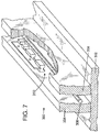
- FIG. 7 (corresponding to FIG. 11 of US 7589601 ) illustrates the multi-section probe of FIG. 6 in the context of a slab line transmission line 300.
- the line 300 includes a base plate 302 and separated parallel ground plane slabs 304, 306 mounted transversely on the top of the base plate.
- a center conductor 308 is supported between the ground plane slabs 304, 306.
- the probe structure 200 may be mounted for movement along the center conductor, and also transversely to the center conductor, as illustrated with respect to FIG. 4A .
- a multi-section probe may be mounted on a carriage as depicted in FIG. 4A , and the whole probe moved along the center conductor to control the phase.
- FIG. 4A illustrates an exemplary embodiment of a two-carriage impedance tuner 50, with two carriages 60 and 70.
- the tuner 50 includes a pair of opposed or end walls 52 and 54 on which the center conductor 10 is supported by dielectric bushings (not shown). The end walls are mounted to a bottom plate 55. The opposed conductive ground planes 12, 14 are supported between the end walls.
- RF connectors 56, 58 are provided for making electrical connection to the center conductor on opposed sides of the tuner. Connector 56 is typically connected or coupled to a device under test (DUT).
- DUT device under test
- probe carriages 60 and 70 are mounted for movement along an axis parallel to the center conductor 10.
- the carriages are mounted on guide rails (not shown in FIG. 4A ).
- One rail may have a linear gear rack, for engagement by a rotatable gear mounted on each carriage and driven by a carriage motor, typically a stepper motor, although other types of motors may alternately be employed.
- a carriage motor typically a stepper motor, although other types of motors may alternately be employed.
- a carriage motor By driving the rotatable gear with the carriage motor, a carriage can be moved along the horizontal direction. Since each carriage motor can be independently driven, this allows the carriages to be positioned independently of each other.
- Other arrangements for positioning the carriage may also be employed, e.g. drive belts or leadscrews.
- Carriage 60 has a sensor 62 mounted on the carriage side facing end wall 52, which is configured to sense a pin or other feature 52A extending from the end wall.
- carriage 70 has a sensor 72 mounted on the carriage side facing end wall 54, which is configured to sense a pin or other feature 54A extending from the end wall 54.
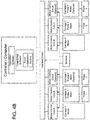
- FIG. 4B is a simplified schematic block diagram illustrating an exemplary embodiment of features for an exemplary two-carriage impedance tuner system such as tuner system 50.
- a controller/computer may be a device or system remotely located relative to the impedance tuner 50, or in some cases built into the tuner.
- the controller/computer is typically programmable, and includes application software configured to control operation of the tuner, e.g. for testing DUTs in various test modes, e.g. without limitation load pull, source pull, noise parameter measurements, and ruggedness testing.
- the controller/computer also includes tuner driver software configured to provide drive commands to the tuner motors, under control of the application software.
- the tuner driver software includes a tuner initialization routine or algorithm, configured to initialize the tuner upon power up or reset.
- the initialization routine in this embodiment carries out the carriage initialization to determine initial or zero positions of the carriage motors.
- the controller/computer is connected to an interface circuit, e.g. a USB interface circuit, to which are connected the motor control circuits for the carriage (horizontal drive) and probe (vertical drive) motors and, in an exemplary embodiment, the sensors, including sensors 62, 72 and 74.
- each carriage 60 and 70 hold two probes spaced apart along the horizontal direction, and each probe is vertically (i.e. transverse to the axis of the center conductor) positioned by a probe motor (1 and 2 for each carriage) from a position very close, but not in contact with, the center conductor to a position spaced away from the center conductor by a sufficient distance that the probe in this position does not affect the fields to a significant degree.
- the probe motors each are configured to position the corresponding probe at a selected vertical position within this range of motion.
- the carriage 1 (60) motor (horizontal drive) is driven by a motor control circuit, and the respective carriage 1 probe 1 and carriage 1 probe 2 motor (vertical drive) are each driven by a motor control circuit, all under control of the controller/computer.
- the carriage 2 (70) motor (horizontal drive) is driven by a motor control circuit, and the respective carriage 2 probe 3 and carriage 2 probe 4 motor (vertical drive) are each driven by a motor control circuit, all under control of the controller/computer.
- the sensor signals may be processed by the controller/computer, or by the motors or the motor control circuits, depending on the implementation. In other embodiments, each carriage may support a single probe, or more than two probes.
- FIG. 4D is an image of an exemplary two carriage tuner 50 as described in FIGS. 4A-4C .
- An ultra-wideband tuner as described herein is advantageous for several reasons.
- the first is that the user might have needs in different frequency bands. With standard tuners, the user might need to purchase several tuners to meet his requirements. As an example, if one tuner goes from 0.4-4 GHz and another from 1.8-18 GHz, and the user had requirements at both 1 GHz and 12 GHz, he would need to buy two tuners. With one ultra-wideband tuner, the customer would be able to purchase a single unit to meet his various requirements.
- a second scenario is a customer who wishes to measure the wideband performance of a transistor for some parameter, say noise parameters.
- the customer would need to take the first tuner, perform the system assembly, calibration, measurement at the operating frequency limits of the tuner, then disassemble his system, replace tuners, and start again.
- the measurements can be done in one connection.
- the first probe is positioned into the slab line while probes P2, P3, P4 are retracted, and the measurements are taken under the operating bandwidth of the tuner.
- probe P1 is retracted along with probes P3 and P4, and probe P2 is lowered into the slab line and the measurements are repeated, with similar operations repeated for probes P3 and P4.
- FIG 5 illustrates an exemplary three-carriage tuner where each carriage 60, 70 and 80 holds two non-similar probes.
- Carriage 60 holds probes P1 and P2, carriage 70 probes P3 and P4, and carriage 80 probes P5 and P6
- Each probe has a different geometry and therefore has a different operating bandwidth.
- the tuner is configured to achieve an ultra-wide band of operation.
- Each carriage in an exemplary embodiment of a multi-carriage impedance tuner may have one or more probes, and each carriage has at least one probe that is different from at least one probe on at least one of the other carriages.
- each probe carriage has at least N probes where N is an integer equal to or greater than one, and at least one of said N probes is mechanically different or of different nominal geometry from all probes on at least one of the other carriages so that each such different probe has an non-identical frequency response relative to the other different probes.
- N an integer equal to or greater than one
- N an integer equal to or greater than one
- at least one of said N probes is mechanically different or of different nominal geometry from all probes on at least one of the other carriages so that each such different probe has an non-identical frequency response relative to the other different probes.
- some probes may be the same on different carriages, although unnecessary for a "single-active-probe-at-a-time" mode of operation.
- Probes P1, P3, P5, P6 may have different geometries with different frequency responses, e.g. non-overlapping, contiguous frequency responses, and may be used in a "single-active-probe-at-a-time" mode of operation.
- Probe P2 on carriage 60 and probe P4 on carriage 70 may be identical probes, which may be useful in a harmonic tuning mode of operation of the tuner.
Landscapes
- Measurement Of Resistance Or Impedance (AREA)
- Measuring Leads Or Probes (AREA)
Claims (13)
- Mechanischer Impedanztuner (50) mit wenigstens zwei Sondenschlitten, wobei der Tuner Folgendes umfasst:einen mittleren Leiter (10);wenigstens zwei Sondenschlitten, die zum Bewegen entlang einer Achse parallel zum mittleren Leiter montiert sind, wobei die genannten wenigstens zwei Sondenschlitten einen ersten Sondenschlitten (60) und einen zweiten Sondenschlitten (70) beinhalten;wobei jeder Sondenschlitten wenigstens N Sonden (P1, P2, ...) hat, wobei N eine ganze Zahl gleich oder größer als eins ist, und wenigstens eine der genannten N Sonden von einem der genannten Sondenschlitten eine andere Nenngeometrie hat als alle Sonden auf wenigstens einem der anderen Schlitten;ein Schlittenantriebssystem zum Bewegen jedes Sondenschlittens unabhängig entlang der genannten Achse parallel zum mittleren Leiter;ein Sondenantriebssystem zum Bewegen jeder Sonde unabhängig in einer Richtung quer zum mittleren Leiter; undeine Steuerung, konfiguriert zum Betreiben des genannten Sondenschlittenantriebssystems und des genannten Sondenantriebssystems.
- Tuner nach Anspruch 1, wobei die Steuerung zum Betreiben des Sondenschlittenantriebssystems und des Sondenantriebssystems in einem Eine-Sonde-nach-der-anderen-Betriebsmodus konfiguriert ist, in dem nur eine der genannten Sonden als aktive Sonde zum Beeinflussen einer vom Tuner präsentierten Impedanz benutzt wird und die anderen Sonden in inaktiven Positionen platziert werden, in denen die anderen Sonden die genannte Impedanz nicht beeinflussen.
- Tuner nach Anspruch 2, wobei Frequenzantworten von jeder der genannten Sonden eine andere Geometrie haben, wenn sie als aktive Sonde nicht überlappend sind.
- Tuner nach Anspruch 3, wobei die genannten Frequenzantworten zusammenhängende Betriebsfrequenzbänder aufweisen, wobei die zusammengesetzte Betriebsfrequenzbandbreite des Tuners die Zusammensetzung der zusammenhängenden Frequenzbänder ist.
- Tuner nach Anspruch 1, wobei wenigstens eine Sonde auf einem der genannten Schlitten eine identische oder nahezu identische Frequenzantwort wie eine andere Sonde auf einem anderen der genannten Schlitten hat.
- Tuner nach Anspruch 5, wobei die genannten Sondengeometrien zum Bereitstellen jeweiliger zusammenhängender Frequenzantwortbänder von 0,6 - 2,8 GHz, 2,8 - 4,6 GHz, 2,8 - 8 GHz bzw. 8 - 18 GHz konfiguriert sind.
- Tuner nach Anspruch 1, wobei die Geometrie jeder Sonde durch Merkmale einschließlich Höhen-, Breiten- und Längenmaßen der Sonde bestimmt wird.
- Tuner nach Anspruch 7, wobei die genannten Sonden unterschiedliche Nenngeometrien mit denselben Breiten- und Höhenmaßen mit unterschiedlichen Sondenlängenmaßen haben, um unterschiedliche Frequenzantworten zu erzielen.
- Tuner nach Anspruch 1, wobei die genannten Sonden mit unterschiedlichen Geometrien jeweils eine Mehrsektionssonde umfassen und jede Sektion einer gegebenen der genannten Mehrsektionssonden eine andere Geometrie hat als eine entsprechende Sektion einer anderen der genannten Mehrsektionssonden.
- Verfahren zum Betreiben eines mechanischen Impedanztuners in einem Eine-aktive-Sonde-nach-der-anderen-Mess- oder Kalibrationsmodus, das Folgendes beinhaltet:(i) Initialisieren eines mechanischen Impedanztuners (50) mit wenigstens zwei Sondenschlitten, wobei der Tuner einen mittleren Leiter aufweist, wobei wenigstens zwei Sondenschlitten zum Bewegen entlang einer Achse parallel zum mittleren Leiter montiert sind, wobei die genannten wenigstens zwei Sondenschlitten einen ersten Sondenschlitten (60) und einen zweiten Sondenschlitten (70) umfassen, wobei jeder Sondenschlitten wenigstens N Sonden (P1, P2, ...) hat, wobei N eine ganze Zahl gleich oder größer als eins ist, und wenigstens eine der genannten N Sonden von einem der genannten Schlitten eine andere Nenngeometrie hat als alle Sonden auf wenigstens einem der anderen Schlitten;(ii) Bewegen aller genannten Sonden außer einer zu inaktiven Positionen, in denen die Sonden eine vom Tuner präsentierte Impedanz nicht beeinflussen, und Einleiten eines Mess- oder Kalibrationsprozesses mit der genannten einen Sonde;(iii) Wiederholen von Schritt (ii) für wenigstens eine der anderen der genannten N Sonden mit einer anderen Geometrie.
- Tuner nach Anspruch 1, wobei jede der genannten N Sonden des genannten einen Sondenschlittens eine andere Nenngeometrie hat als jede andere Sonde auf dem genannten einen Sondenschlitten.
- Tuner nach Anspruch 1, wobei jede Sonde in dem Tuner eine andere Geometrie hat als jede andere Sonde in dem Tuner.
- Tuner nach Anspruch 2, wobei jede Sonde in dem Tuner eine andere Geometrie hat als jede andere Sonde in dem Tuner.
Applications Claiming Priority (2)
| Application Number | Priority Date | Filing Date | Title |
|---|---|---|---|
| US201361860792P | 2013-07-31 | 2013-07-31 | |
| PCT/US2014/048961 WO2015017578A1 (en) | 2013-07-31 | 2014-07-30 | Ultra-wideband impedance tuner |
Publications (2)
| Publication Number | Publication Date |
|---|---|
| EP3028339A1 EP3028339A1 (de) | 2016-06-08 |
| EP3028339B1 true EP3028339B1 (de) | 2019-07-17 |
Family
ID=52427124
Family Applications (1)
| Application Number | Title | Priority Date | Filing Date |
|---|---|---|---|
| EP14761715.3A Active EP3028339B1 (de) | 2013-07-31 | 2014-07-30 | Ultrabreitbandiger impedanztuner |
Country Status (5)
| Country | Link |
|---|---|
| US (1) | US9712134B2 (de) |
| EP (1) | EP3028339B1 (de) |
| CN (1) | CN105409053B (de) |
| CA (1) | CA2919222C (de) |
| WO (1) | WO2015017578A1 (de) |
Families Citing this family (4)
| Publication number | Priority date | Publication date | Assignee | Title |
|---|---|---|---|---|
| US11119140B1 (en) * | 2017-08-31 | 2021-09-14 | Christos Tsironis | Impedance pattern generation for noise parameter measurement system |
| US11879920B1 (en) * | 2020-07-14 | 2024-01-23 | Christos Tsironis | High power dual probe tuner and method |
| US11733280B1 (en) * | 2021-10-29 | 2023-08-22 | Christos Tsironis | Load pull system using two-probe waveguide tuner |
| US12519458B1 (en) * | 2023-11-30 | 2026-01-06 | Christos Tsironis | Low frequency load pull tuner using dielectric filled spiral airline |
Family Cites Families (12)
| Publication number | Priority date | Publication date | Assignee | Title |
|---|---|---|---|---|
| US7034629B2 (en) * | 2001-12-31 | 2006-04-25 | Christos Tsironis | High frequency, high reflection pre-matching tuners with variable zero initialization |
| US7053628B1 (en) | 2003-11-07 | 2006-05-30 | Christos Tsironis | High reflection microwave tuner using metal-dielectric probe and method |
| US7248866B1 (en) * | 2003-11-14 | 2007-07-24 | Christos Tsironis | Frequency selective load pull tuner and method |
| US7009463B2 (en) * | 2004-08-02 | 2006-03-07 | Philippe Boulerne | Harmonic reflective load-pull tuner |
| US7589601B2 (en) | 2005-09-07 | 2009-09-15 | Maury Microwave, Inc. | Impedance tuner systems and probes |
| US7280012B2 (en) * | 2006-01-24 | 2007-10-09 | Philippe Boulerne | Multi-probes as single RF tuning element for RF slide-screw tuners |
| US8212628B1 (en) | 2009-06-03 | 2012-07-03 | Christos Tsironis | Harmonic impedance tuner with four wideband probes and method |
| US8188816B1 (en) | 2010-06-14 | 2012-05-29 | Christos Tsironis | Compact harmonic impedance tuner |
| US8907750B2 (en) | 2010-08-25 | 2014-12-09 | Maury Microwave, Inc. | Systems and methods for impedance tuner initialization |
| US8823392B2 (en) | 2011-04-06 | 2014-09-02 | Maury Microwave, Inc. | Web-enabled controller for impedance tuner systems |
| US8427255B1 (en) | 2011-09-21 | 2013-04-23 | Christos Tsironis | Self adjustable probes for slide screw impedance tuners |
| CN202583335U (zh) * | 2011-09-28 | 2012-12-05 | 茂瑞微波测量设备有限公司 | 阻抗调谐器 |
-
2014
- 2014-07-30 US US14/446,855 patent/US9712134B2/en active Active
- 2014-07-30 CA CA2919222A patent/CA2919222C/en active Active
- 2014-07-30 EP EP14761715.3A patent/EP3028339B1/de active Active
- 2014-07-30 CN CN201480042319.9A patent/CN105409053B/zh active Active
- 2014-07-30 WO PCT/US2014/048961 patent/WO2015017578A1/en not_active Ceased
Non-Patent Citations (1)
| Title |
|---|
| None * |
Also Published As
| Publication number | Publication date |
|---|---|
| CA2919222A1 (en) | 2015-02-05 |
| CN105409053B (zh) | 2020-02-14 |
| CA2919222C (en) | 2018-03-13 |
| US20150035613A1 (en) | 2015-02-05 |
| US9712134B2 (en) | 2017-07-18 |
| WO2015017578A1 (en) | 2015-02-05 |
| CN105409053A (zh) | 2016-03-16 |
| EP3028339A1 (de) | 2016-06-08 |
Similar Documents
| Publication | Publication Date | Title |
|---|---|---|
| US7589601B2 (en) | Impedance tuner systems and probes | |
| CA2919222C (en) | Ultra-wideband impedance tuner | |
| US10700402B1 (en) | Compact millimeter-wave tuner | |
| US20070004238A1 (en) | Compliant electro-mechanical device | |
| US9620842B1 (en) | Compact two probe impedance tuner | |
| US9602072B1 (en) | Compact impedance tuner | |
| KR101634258B1 (ko) | 테스트 프로드 | |
| US11621468B1 (en) | Combination probes for load pull tuner | |
| JP2009502075A (ja) | 同軸自動インピーダンス・アダプタ | |
| JP7065502B2 (ja) | 誘電体材料評価装置 | |
| Koenen et al. | A self-aligning cylindrical sliding short plunger for millimeter-wave rectangular waveguides and its application in a reflection-type phase shifter | |
| US10097165B1 (en) | High gamma compact harmonic tuner | |
| JP5862948B2 (ja) | アンテナ装置 | |
| US8461946B1 (en) | Impedance tuners with mechanical stop | |
| CN215375597U (zh) | 开放式共振腔结构 | |
| US10560067B2 (en) | Broadband probes for impedance tuners | |
| JP2007010522A (ja) | スルー標準器基板及びライン標準器基板 | |
| WO2015145989A1 (ja) | 導波管変換器および導波管変換方法 | |
| JP4734655B2 (ja) | アンテナ装置 | |
| EP3796013A1 (de) | Zur aufnahme einer radiofrequenzsonde zum testen einer elektrischen vorrichtung konfigurierte schnittstelle und verfahren zum testen einer auf einem substrat angeordneten elektrischen vorrichtung | |
| JP2025047621A (ja) | 線路接続器 | |
| WO2007145097A1 (ja) | アンテナ | |
| JP2006101557A (ja) | 高周波フィルタの調整方法及び調整装置 | |
| JPH11118863A (ja) | 高周波測定コネクタ装置 |
Legal Events
| Date | Code | Title | Description |
|---|---|---|---|
| PUAI | Public reference made under article 153(3) epc to a published international application that has entered the european phase |
Free format text: ORIGINAL CODE: 0009012 |
|
| 17P | Request for examination filed |
Effective date: 20160224 |
|
| AK | Designated contracting states |
Kind code of ref document: A1 Designated state(s): AL AT BE BG CH CY CZ DE DK EE ES FI FR GB GR HR HU IE IS IT LI LT LU LV MC MK MT NL NO PL PT RO RS SE SI SK SM TR |
|
| AX | Request for extension of the european patent |
Extension state: BA ME |
|
| DAX | Request for extension of the european patent (deleted) | ||
| STAA | Information on the status of an ep patent application or granted ep patent |
Free format text: STATUS: EXAMINATION IS IN PROGRESS |
|
| 17Q | First examination report despatched |
Effective date: 20170303 |
|
| GRAP | Despatch of communication of intention to grant a patent |
Free format text: ORIGINAL CODE: EPIDOSNIGR1 |
|
| STAA | Information on the status of an ep patent application or granted ep patent |
Free format text: STATUS: GRANT OF PATENT IS INTENDED |
|
| INTG | Intention to grant announced |
Effective date: 20190205 |
|
| GRAS | Grant fee paid |
Free format text: ORIGINAL CODE: EPIDOSNIGR3 |
|
| GRAA | (expected) grant |
Free format text: ORIGINAL CODE: 0009210 |
|
| STAA | Information on the status of an ep patent application or granted ep patent |
Free format text: STATUS: THE PATENT HAS BEEN GRANTED |
|
| AK | Designated contracting states |
Kind code of ref document: B1 Designated state(s): AL AT BE BG CH CY CZ DE DK EE ES FI FR GB GR HR HU IE IS IT LI LT LU LV MC MK MT NL NO PL PT RO RS SE SI SK SM TR |
|
| REG | Reference to a national code |
Ref country code: GB Ref legal event code: FG4D |
|
| REG | Reference to a national code |
Ref country code: CH Ref legal event code: EP |
|
| REG | Reference to a national code |
Ref country code: IE Ref legal event code: FG4D |
|
| REG | Reference to a national code |
Ref country code: DE Ref legal event code: R096 Ref document number: 602014050152 Country of ref document: DE |
|
| REG | Reference to a national code |
Ref country code: AT Ref legal event code: REF Ref document number: 1156677 Country of ref document: AT Kind code of ref document: T Effective date: 20190815 |
|
| REG | Reference to a national code |
Ref country code: NL Ref legal event code: MP Effective date: 20190717 |
|
| REG | Reference to a national code |
Ref country code: LT Ref legal event code: MG4D |
|
| REG | Reference to a national code |
Ref country code: AT Ref legal event code: MK05 Ref document number: 1156677 Country of ref document: AT Kind code of ref document: T Effective date: 20190717 |
|
| PG25 | Lapsed in a contracting state [announced via postgrant information from national office to epo] |
Ref country code: BG Free format text: LAPSE BECAUSE OF FAILURE TO SUBMIT A TRANSLATION OF THE DESCRIPTION OR TO PAY THE FEE WITHIN THE PRESCRIBED TIME-LIMIT Effective date: 20191017 Ref country code: NL Free format text: LAPSE BECAUSE OF FAILURE TO SUBMIT A TRANSLATION OF THE DESCRIPTION OR TO PAY THE FEE WITHIN THE PRESCRIBED TIME-LIMIT Effective date: 20190717 Ref country code: NO Free format text: LAPSE BECAUSE OF FAILURE TO SUBMIT A TRANSLATION OF THE DESCRIPTION OR TO PAY THE FEE WITHIN THE PRESCRIBED TIME-LIMIT Effective date: 20191017 Ref country code: AT Free format text: LAPSE BECAUSE OF FAILURE TO SUBMIT A TRANSLATION OF THE DESCRIPTION OR TO PAY THE FEE WITHIN THE PRESCRIBED TIME-LIMIT Effective date: 20190717 Ref country code: PT Free format text: LAPSE BECAUSE OF FAILURE TO SUBMIT A TRANSLATION OF THE DESCRIPTION OR TO PAY THE FEE WITHIN THE PRESCRIBED TIME-LIMIT Effective date: 20191118 Ref country code: FI Free format text: LAPSE BECAUSE OF FAILURE TO SUBMIT A TRANSLATION OF THE DESCRIPTION OR TO PAY THE FEE WITHIN THE PRESCRIBED TIME-LIMIT Effective date: 20190717 Ref country code: LT Free format text: LAPSE BECAUSE OF FAILURE TO SUBMIT A TRANSLATION OF THE DESCRIPTION OR TO PAY THE FEE WITHIN THE PRESCRIBED TIME-LIMIT Effective date: 20190717 Ref country code: SE Free format text: LAPSE BECAUSE OF FAILURE TO SUBMIT A TRANSLATION OF THE DESCRIPTION OR TO PAY THE FEE WITHIN THE PRESCRIBED TIME-LIMIT Effective date: 20190717 Ref country code: HR Free format text: LAPSE BECAUSE OF FAILURE TO SUBMIT A TRANSLATION OF THE DESCRIPTION OR TO PAY THE FEE WITHIN THE PRESCRIBED TIME-LIMIT Effective date: 20190717 |
|
| REG | Reference to a national code |
Ref country code: DE Ref legal event code: R119 Ref document number: 602014050152 Country of ref document: DE |
|
| PG25 | Lapsed in a contracting state [announced via postgrant information from national office to epo] |
Ref country code: AL Free format text: LAPSE BECAUSE OF FAILURE TO SUBMIT A TRANSLATION OF THE DESCRIPTION OR TO PAY THE FEE WITHIN THE PRESCRIBED TIME-LIMIT Effective date: 20190717 Ref country code: GR Free format text: LAPSE BECAUSE OF FAILURE TO SUBMIT A TRANSLATION OF THE DESCRIPTION OR TO PAY THE FEE WITHIN THE PRESCRIBED TIME-LIMIT Effective date: 20191018 Ref country code: IS Free format text: LAPSE BECAUSE OF FAILURE TO SUBMIT A TRANSLATION OF THE DESCRIPTION OR TO PAY THE FEE WITHIN THE PRESCRIBED TIME-LIMIT Effective date: 20191117 Ref country code: RS Free format text: LAPSE BECAUSE OF FAILURE TO SUBMIT A TRANSLATION OF THE DESCRIPTION OR TO PAY THE FEE WITHIN THE PRESCRIBED TIME-LIMIT Effective date: 20190717 Ref country code: LV Free format text: LAPSE BECAUSE OF FAILURE TO SUBMIT A TRANSLATION OF THE DESCRIPTION OR TO PAY THE FEE WITHIN THE PRESCRIBED TIME-LIMIT Effective date: 20190717 Ref country code: ES Free format text: LAPSE BECAUSE OF FAILURE TO SUBMIT A TRANSLATION OF THE DESCRIPTION OR TO PAY THE FEE WITHIN THE PRESCRIBED TIME-LIMIT Effective date: 20190717 |
|
| REG | Reference to a national code |
Ref country code: CH Ref legal event code: PL |
|
| PG25 | Lapsed in a contracting state [announced via postgrant information from national office to epo] |
Ref country code: TR Free format text: LAPSE BECAUSE OF FAILURE TO SUBMIT A TRANSLATION OF THE DESCRIPTION OR TO PAY THE FEE WITHIN THE PRESCRIBED TIME-LIMIT Effective date: 20190717 |
|
| REG | Reference to a national code |
Ref country code: BE Ref legal event code: MM Effective date: 20190731 |
|
| PG25 | Lapsed in a contracting state [announced via postgrant information from national office to epo] |
Ref country code: RO Free format text: LAPSE BECAUSE OF FAILURE TO SUBMIT A TRANSLATION OF THE DESCRIPTION OR TO PAY THE FEE WITHIN THE PRESCRIBED TIME-LIMIT Effective date: 20190717 Ref country code: IT Free format text: LAPSE BECAUSE OF FAILURE TO SUBMIT A TRANSLATION OF THE DESCRIPTION OR TO PAY THE FEE WITHIN THE PRESCRIBED TIME-LIMIT Effective date: 20190717 Ref country code: DE Free format text: LAPSE BECAUSE OF NON-PAYMENT OF DUE FEES Effective date: 20200201 Ref country code: DK Free format text: LAPSE BECAUSE OF FAILURE TO SUBMIT A TRANSLATION OF THE DESCRIPTION OR TO PAY THE FEE WITHIN THE PRESCRIBED TIME-LIMIT Effective date: 20190717 Ref country code: EE Free format text: LAPSE BECAUSE OF FAILURE TO SUBMIT A TRANSLATION OF THE DESCRIPTION OR TO PAY THE FEE WITHIN THE PRESCRIBED TIME-LIMIT Effective date: 20190717 Ref country code: PL Free format text: LAPSE BECAUSE OF FAILURE TO SUBMIT A TRANSLATION OF THE DESCRIPTION OR TO PAY THE FEE WITHIN THE PRESCRIBED TIME-LIMIT Effective date: 20190717 |
|
| PG25 | Lapsed in a contracting state [announced via postgrant information from national office to epo] |
Ref country code: CZ Free format text: LAPSE BECAUSE OF FAILURE TO SUBMIT A TRANSLATION OF THE DESCRIPTION OR TO PAY THE FEE WITHIN THE PRESCRIBED TIME-LIMIT Effective date: 20190717 Ref country code: MC Free format text: LAPSE BECAUSE OF FAILURE TO SUBMIT A TRANSLATION OF THE DESCRIPTION OR TO PAY THE FEE WITHIN THE PRESCRIBED TIME-LIMIT Effective date: 20190717 Ref country code: SM Free format text: LAPSE BECAUSE OF FAILURE TO SUBMIT A TRANSLATION OF THE DESCRIPTION OR TO PAY THE FEE WITHIN THE PRESCRIBED TIME-LIMIT Effective date: 20190717 Ref country code: CH Free format text: LAPSE BECAUSE OF NON-PAYMENT OF DUE FEES Effective date: 20190731 Ref country code: IS Free format text: LAPSE BECAUSE OF FAILURE TO SUBMIT A TRANSLATION OF THE DESCRIPTION OR TO PAY THE FEE WITHIN THE PRESCRIBED TIME-LIMIT Effective date: 20200224 Ref country code: LU Free format text: LAPSE BECAUSE OF NON-PAYMENT OF DUE FEES Effective date: 20190730 Ref country code: SK Free format text: LAPSE BECAUSE OF FAILURE TO SUBMIT A TRANSLATION OF THE DESCRIPTION OR TO PAY THE FEE WITHIN THE PRESCRIBED TIME-LIMIT Effective date: 20190717 Ref country code: LI Free format text: LAPSE BECAUSE OF NON-PAYMENT OF DUE FEES Effective date: 20190731 Ref country code: BE Free format text: LAPSE BECAUSE OF NON-PAYMENT OF DUE FEES Effective date: 20190731 |
|
| PLBE | No opposition filed within time limit |
Free format text: ORIGINAL CODE: 0009261 |
|
| STAA | Information on the status of an ep patent application or granted ep patent |
Free format text: STATUS: NO OPPOSITION FILED WITHIN TIME LIMIT |
|
| PG2D | Information on lapse in contracting state deleted |
Ref country code: IS |
|
| PG25 | Lapsed in a contracting state [announced via postgrant information from national office to epo] |
Ref country code: IE Free format text: LAPSE BECAUSE OF NON-PAYMENT OF DUE FEES Effective date: 20190730 |
|
| 26N | No opposition filed |
Effective date: 20200603 |
|
| PG25 | Lapsed in a contracting state [announced via postgrant information from national office to epo] |
Ref country code: SI Free format text: LAPSE BECAUSE OF FAILURE TO SUBMIT A TRANSLATION OF THE DESCRIPTION OR TO PAY THE FEE WITHIN THE PRESCRIBED TIME-LIMIT Effective date: 20190717 |
|
| PG25 | Lapsed in a contracting state [announced via postgrant information from national office to epo] |
Ref country code: CY Free format text: LAPSE BECAUSE OF FAILURE TO SUBMIT A TRANSLATION OF THE DESCRIPTION OR TO PAY THE FEE WITHIN THE PRESCRIBED TIME-LIMIT Effective date: 20190717 |
|
| PG25 | Lapsed in a contracting state [announced via postgrant information from national office to epo] |
Ref country code: MT Free format text: LAPSE BECAUSE OF FAILURE TO SUBMIT A TRANSLATION OF THE DESCRIPTION OR TO PAY THE FEE WITHIN THE PRESCRIBED TIME-LIMIT Effective date: 20190717 Ref country code: HU Free format text: LAPSE BECAUSE OF FAILURE TO SUBMIT A TRANSLATION OF THE DESCRIPTION OR TO PAY THE FEE WITHIN THE PRESCRIBED TIME-LIMIT; INVALID AB INITIO Effective date: 20140730 |
|
| PG25 | Lapsed in a contracting state [announced via postgrant information from national office to epo] |
Ref country code: MK Free format text: LAPSE BECAUSE OF FAILURE TO SUBMIT A TRANSLATION OF THE DESCRIPTION OR TO PAY THE FEE WITHIN THE PRESCRIBED TIME-LIMIT Effective date: 20190717 |
|
| P01 | Opt-out of the competence of the unified patent court (upc) registered |
Effective date: 20230426 |
|
| PGFP | Annual fee paid to national office [announced via postgrant information from national office to epo] |
Ref country code: GB Payment date: 20250619 Year of fee payment: 12 |
|
| PGFP | Annual fee paid to national office [announced via postgrant information from national office to epo] |
Ref country code: FR Payment date: 20250620 Year of fee payment: 12 |