EP3028064B1 - Sonarsystem mit einer gekrümmten antenne oder einer für die übertragung desselben übertragungsmusters wie die gekrümmte antenne konfigurierten antenne - Google Patents
Sonarsystem mit einer gekrümmten antenne oder einer für die übertragung desselben übertragungsmusters wie die gekrümmte antenne konfigurierten antenne Download PDFInfo
- Publication number
- EP3028064B1 EP3028064B1 EP14744083.8A EP14744083A EP3028064B1 EP 3028064 B1 EP3028064 B1 EP 3028064B1 EP 14744083 A EP14744083 A EP 14744083A EP 3028064 B1 EP3028064 B1 EP 3028064B1
- Authority
- EP
- European Patent Office
- Prior art keywords
- antenna
- sonar system
- emitting surface
- seabed
- emission
- Prior art date
- Legal status (The legal status is an assumption and is not a legal conclusion. Google has not performed a legal analysis and makes no representation as to the accuracy of the status listed.)
- Active
Links
Images



Classifications
-
- G—PHYSICS
- G01—MEASURING; TESTING
- G01S—RADIO DIRECTION-FINDING; RADIO NAVIGATION; DETERMINING DISTANCE OR VELOCITY BY USE OF RADIO WAVES; LOCATING OR PRESENCE-DETECTING BY USE OF THE REFLECTION OR RERADIATION OF RADIO WAVES; ANALOGOUS ARRANGEMENTS USING OTHER WAVES
- G01S7/00—Details of systems according to groups G01S13/00, G01S15/00, G01S17/00
- G01S7/52—Details of systems according to groups G01S13/00, G01S15/00, G01S17/00 of systems according to group G01S15/00
- G01S7/523—Details of pulse systems
- G01S7/524—Transmitters
-
- G—PHYSICS
- G01—MEASURING; TESTING
- G01S—RADIO DIRECTION-FINDING; RADIO NAVIGATION; DETERMINING DISTANCE OR VELOCITY BY USE OF RADIO WAVES; LOCATING OR PRESENCE-DETECTING BY USE OF THE REFLECTION OR RERADIATION OF RADIO WAVES; ANALOGOUS ARRANGEMENTS USING OTHER WAVES
- G01S15/00—Systems using the reflection or reradiation of acoustic waves, e.g. sonar systems
- G01S15/88—Sonar systems specially adapted for specific applications
- G01S15/89—Sonar systems specially adapted for specific applications for mapping or imaging
- G01S15/8902—Side-looking sonar
-
- G—PHYSICS
- G10—MUSICAL INSTRUMENTS; ACOUSTICS
- G10K—SOUND-PRODUCING DEVICES; METHODS OR DEVICES FOR PROTECTING AGAINST, OR FOR DAMPING, NOISE OR OTHER ACOUSTIC WAVES IN GENERAL; ACOUSTICS NOT OTHERWISE PROVIDED FOR
- G10K11/00—Methods or devices for transmitting, conducting or directing sound in general; Methods or devices for protecting against, or for damping, noise or other acoustic waves in general
- G10K11/18—Methods or devices for transmitting, conducting or directing sound
- G10K11/26—Sound-focusing or directing, e.g. scanning
- G10K11/34—Sound-focusing or directing, e.g. scanning using electrical steering of transducer arrays, e.g. beam steering
- G10K11/341—Circuits therefor
- G10K11/346—Circuits therefor using phase variation
-
- G—PHYSICS
- G10—MUSICAL INSTRUMENTS; ACOUSTICS
- G10K—SOUND-PRODUCING DEVICES; METHODS OR DEVICES FOR PROTECTING AGAINST, OR FOR DAMPING, NOISE OR OTHER ACOUSTIC WAVES IN GENERAL; ACOUSTICS NOT OTHERWISE PROVIDED FOR
- G10K11/00—Methods or devices for transmitting, conducting or directing sound in general; Methods or devices for protecting against, or for damping, noise or other acoustic waves in general
- G10K11/18—Methods or devices for transmitting, conducting or directing sound
- G10K11/26—Sound-focusing or directing, e.g. scanning
- G10K11/34—Sound-focusing or directing, e.g. scanning using electrical steering of transducer arrays, e.g. beam steering
- G10K11/341—Circuits therefor
- G10K11/348—Circuits therefor using amplitude variation
Definitions
- the field of the invention is that of sonars.
- the invention relates more particularly to sonars used for imaging the seabed.
- the field of application of these sonars relates to the detection of objects by reflection of sound waves on the objects and on the seabed and by processing of the reflected waves.
- the sonars include a transmitting antenna emitting an acoustic beam directed towards the seabed covering a useful angular sector starting from the antenna and delimited by two directions inclined relative to the horizontal and to the vertical.
- the useful angular sector delimits the zone of the seabed that the sonar is intended to image.
- the sonar is intended to image the zone of the seabed intercepted by the angular sector.
- sonars are usually mounted on a submersible carrier such as a towed or autonomous underwater vehicle or under the hull of a surface vessel.
- Current transmitting antennas are cylindrical antennas or plane antennas. These antennas have an emission pattern comprising a main lobe and secondary lobes, the emission pattern being symmetrical with respect to the maximum of the main lobe.
- planar antennas have a sinx / x emission pattern.
- the antennas are usually configured so that the maximum energy is emitted between the first and the second direction, that is to say within the useful angular sector.
- the aim of the invention is to overcome at least one of these drawbacks.
- the invention relates to a sonar system intended to image the seabed, comprising at least one transmitting antenna intended to emit an acoustic beam covering a useful angular sector delimited by a first direction and a second direction, the distance between the antenna and the seabed being greater in the first direction than in the second direction.
- the antenna is configured so as to form an emission pattern, the maximum of which is located substantially in the first direction and decreasing from the first direction to the second direction and from the first direction. in the direction opposite to the second direction, the energy attenuation being faster in the direction opposite to the second direction than towards the second direction.
- Such a sonar system has greater autonomy than those of the prior art since it makes it possible to reduce the sound energy sent by the transmitting antenna to image the seabed.
- the sound energy sent by an antenna being directly linked to the electrical power necessary to supply the antenna, the invention makes it possible to produce sonar systems that consume little energy. If the transmitting antenna is carried by an autonomous underwater vehicle, the autonomy of the latter is greater.
- the sonar according to the invention requires a transmission antenna of smaller size than the antennas of the prior art.
- the sonar system according to the invention makes it possible to reduce the size of the antenna without degrading its performance. The integration of the sonar system on carriers is thus facilitated.
- the transmitting antenna emitted maximum energy between the first and second directions.
- the configuration of the transmitting antenna according to the invention makes it possible, by sending maximum energy in the first direction, to limit the surplus energy sent in the other directions of the useful sector.
- the maximum energy is sent where the need is maximum, that is to say according to the direction of maximum range.
- the sound energy sent outside the useful angular sector, in particular beyond the first direction not serving to image the seabed it is a matter of lost sound energy.
- the fact of configuring an antenna so that it generates an emission pattern decreasing more quickly from the first direction and in the direction opposite to the second direction, than between the first and the second direction allows to limit the sound energy. emitted and avoids consuming energy unnecessarily.
- the sound energy emitted beyond a horizontal direction reverberates on the surface of the water, which causes noise to the images obtained by the sonar system.
- the emission diagram according to the invention makes it possible to limit the noise on the sonar images and thus to provide good quality sonar images, in particular in shallow depths.
- the emission diagram is such that for each direction comprised between a third direction, comprised between the first direction and the second direction, and the second direction, the energy attenuation, with respect to the energy emitted according to the first direction, is substantially equal to the attenuation of the sound energy necessary to image an ideal seabed plane in this direction with respect to the sound energy necessary to image the ideal seabed in the first direction.
- the third direction is a direction for which the attenuation is 3dB, the angle formed between the third direction and the first direction being less than 3 degrees.
- the transmitting antenna comprises an transmitting surface comprising a variable radius of curvature, so as to form said transmission pattern.
- the emitting surface is curved.
- the radius of curvature of the emitting surface increases with the distance separating the point of the emitting surface considered from the ideal seabed in a direction perpendicular to the ideal seabed.
- the curve formed by the emitting surface in a section plane of the antenna perpendicular to its longitudinal axis is formed by a single transducer.
- the antenna comprises an emitting surface forming a curve in a section plane of the antenna perpendicular to its longitudinal axis, said curve being formed by a plurality of transducers, said antenna comprising a feed device supplying the respective transducers with power. a same signal assigned respective phase shifts and / or amplitude modulation so as to form said emission pattern.
- the emitting surface is flat or cylindrical.
- said transmitting antenna can be depointed in bearing.
- the system comprises a carrier, the transmitting antenna being installed on the carrier.
- the transmitting antenna is arranged so that its transmitting surface extends longitudinally along an axis parallel to the direction of movement of the carrier.
- the system comprises two transmit antennas fixed to the port and starboard side of the carrier.
- the first direction is the direction of maximum range of the sonar system and the second direction is the direction of minimum range of the sonar system.
- a sonar system intended to image the seabed 5.
- This device comprises two lateral sonars 1, 1 'mounted on a submersible carrier 2 navigating under the surface 4 of the water.
- the carrier 2 is an underwater vehicle towed by a surface vessel 3 by means of a cable 3a.
- the carrier can be an autonomous underwater vehicle, or the submerged bottom of a surface vessel.
- the sonar system can also include at least one transmitting antenna towed by the carrier.
- the carrier 2 is configured so as to navigate in a direction x of advance. It is preferably intended to navigate at a constant altitude relative to the seabed 5.
- the sonar system comprises two sonars 1, 1 'each comprising a transmitting antenna 10, 10'.
- the underwater vehicle is advantageously configured so that when it is navigating at a fixed height relative to the seabed, the transmitting antennas 10, 10 'are located at a fixed height h relative to the seabed.
- Each transmitting antenna is configured and positioned so as to emit an acoustic beam, in the direction of the seabed 5. More precisely, each transmitting antenna 10, 10 'is configured and positioned so as to cover an angular sector 4, 4 'useful having an angular opening ⁇ delimited by a first direction d1, d1' and a second direction d2, d2 'starting from the corresponding transmitting antenna and oriented towards the seabed.
- each antenna is configured so as to emit an acoustic beam which will cover the useful angular sector which is assigned to it, that is to say extend at least over the entire angular opening ⁇ delimited by lines d1 and d2 or d1 'and d2'.
- the antenna is positioned on the carrier and possibly configured so that the beam in the useful area is directed towards the seabed 5.
- the directions d1, d2 and d1 ′, d2 ′ are inclined with respect to a direction connecting the antenna and an ideal seabed, this direction being perpendicular to the ideal seabed.
- the directions d1, d2 and d1 ′, d2 ′ are located in a quarter-plane delimited by this direction and the ideal seabed.
- the useful angular sector 4, 4 ′ defines the seabed zone which is imaged by the sonar 1, 1 ′.
- the first distance D1, D1 'separating the antenna 10, 10' from the seabed in the direction d1, d1 ' is greater than the second distance D2, D2' separating the antenna in the second direction d2, d2 '.
- the first distance D1, D1 ' is the maximum range of the corresponding sonar 1, 1'. This is advantageously the maximum range of the sonar, or detection range of the sonar, for the mission in question corresponding to the maximum distance that must separate the antenna from the seabed so that the sonar can image it.
- the first direction d1, d1 ' is the direction of maximum range of the sonar. This is the direction in which the distance between the seabed and the sonar is maximum in the useful sector imaged by the sonar.
- the second direction d2 d2 ′ is the direction of minimum range of the sonar. This is the direction in which the distance separating the sonar from the seabed is minimum in the useful sector.
- the distance D2, D2 ' is the minimum range of sonar.
- the directions d1 and d2 and respectively d1 ′, d2 ′ delimit respective useful sectors of the sonar, that is to say the sectors actually imaged by the sonar.
- the angular opening ⁇ of the useful sector is typically between 10 ° and 90 °.
- lateral sonars radiate extremely fine beams in bearing. In other words, the opening in deposit is smaller than the opening in site.
- the directions d1 and d2 are located in the plane (y, z) perpendicular to the direction x of advance of the carrier 2.
- the direction y is a horizontal direction perpendicular to the direction of advance x.
- the z direction is a vertical direction.
- the vertical direction is the direction perpendicular to the horizontal plane formed by the seabed 5.
- the first angle ⁇ 1 and the second angle ⁇ 2 are the angles formed between a horizontal plane P passing through the antenna 10 and the respective directions d1 and d2. They are called site angle. These angles are defined, for a given altitude h of the carrier 2 with respect to the seabed, so that the useful sector covers a predefined swath F.
- the swath F is the horizontal distance separating the directions d1 and d2 on the seabed 5. This distance is, in the embodiment of the figure, calculated perpendicular to the forward direction x of the carrier 2.
- These angles ⁇ 1 and ⁇ 2 are not zero and negative.
- the absolute value of ⁇ 1 is less than that of ⁇ 2.
- first antenna 10 and not in the second antenna 10 ′.
- the emission pattern of the latter being the same as that of the first antenna 10 but defined with respect to the directions d1 ′ and d2 ′.
- FIG. 3 there is shown an example of the emission pattern of the antenna 10.
- the angle at which the emission pattern varies is here the elevation angle ⁇ .
- the x-axis represents the axis of the elevation angles ⁇ between the horizontal plane P parallel to the ideal seabed passing through the antenna and the directions starting from the antenna 10.
- the point O from which the directions d1 and d2 start is a point located behind the emitting or emitting surface of the antenna 10.
- the horizontal plane P passes through this point.
- the elevation angle ⁇ of a direction is counted negatively when heading towards a point below the horizontal plane P.
- the ordinate axis corresponds to the attenuation DE in decibels (dB) with respect to the maximum of the directivity diagram.
- the transmitting antenna 10 is configured and arranged so as to form a transmission pattern, the maximum M of which is situated substantially in the first direction d1, that is to say at the level of the first elevation angle 01, and decreasing from the first direction d1 to the second direction d2 and from the first direction in the direction opposite to the second direction d2.
- This diagram includes a single maximum with 0dB attenuation. In other words, the antenna emits maximum energy only in one direction. This is an absolute maximum.
- This direction is substantially the direction d1.
- the direction in which the antenna emits the most energy has an elevation angle equal to lying in the range [ ⁇ 1 - 0.5 °; ⁇ 1 + 0.5 °].
- the emission pattern oscillates, from direction d1 to direction d2 and from direction d1 to the horizontal, around average curves M1, M2 decreasing substantially monotonically in these two directions.
- the envelopes E1, E2 connecting the local maxima of the emission pattern on either side of the absolute maximum M are curves decreasing in a substantially monotonic manner.
- the energy attenuation is faster, from the first direction d1, in the direction opposite to the second direction d2 than towards the second direction d2.
- the average slope of the average curve or of the envelope defined above is less important on the side of the second direction d2 than on the other side of the first direction d1.
- this characteristic makes it possible to save energy and limit the degradation of sonar images. In fact, it maximizes the sound energy emitted in the useful angular sector and minimizes the sound energy emitted outside this sector, in particular towards higher elevation angles.
- the antenna emission pattern is such that for each direction comprised between the second d2 and a direction d3 comprised between d1 and d2 and for which the attenuation is substantially equal to 3dB, the energy attenuation, by report to the maximum energy M sent according to the maximum emission direction d1, is substantially equal to the attenuation of the sound energy necessary to image an ideal seabed plane in this direction with respect to the sound energy necessary to image the ideal seabed in the first direction d1.
- d3 is the direction closest to d1 (between d1 and d2) for which the attenuation is equal to 3dB or else it can be the direction (between d1 and d2) for which the first average curve M1 is equal to 3dB.
- the transmitting antenna emits, in the first direction d1, sound energy substantially equal to the energy necessary and sufficient to image the seabed in this direction
- the sound energy emitted in each direction between the directions d3 and d2 is substantially equal to the energy necessary and sufficient to image the seabed in this direction.
- This configuration is optimal in terms of energy sent to the useful sector since the energy sent to the ideal seabed is neither more nor less than the energy necessary and sufficient to image the ideal seabed in each direction between the third direction and second direction.
- the energy attenuation is exactly compensated by the shape of the emission pattern.
- the angle formed between ⁇ 3 and ⁇ 1 is less than 3 degrees.
- the attenuation is at least equal to 15 dB.
- the angle direction ⁇ A is located beyond the direction d2 with respect to the direction d1 and the angle direction ⁇ B is located on the other side of the direction d2 with respect to the direction d1.
- the angles which are located beyond ⁇ A and ⁇ B with respect to d1 are the angles which are located beyond ⁇ A when starting from d1 one goes in the direction of d1 towards d2 and respectively the angles which are located beyond ⁇ B when starting from d1 we go in the direction of d2 towards d1.
- the absolute value of the difference between ⁇ B and ⁇ 1 is less than the absolute value of the difference between ⁇ A and ⁇ 1 and preferably less than the absolute value between ⁇ 2 and ⁇ 1.
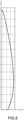
- the desired emission pattern is obtained by means of a transmission antenna 10 comprising an emitting surface 6 whose radius of curvature is variable.
- the curvature of the transmitting surface of the antenna is adjusted, by those skilled in the art, so as to obtain the desired emission pattern.
- the emitting surface can have sharp angles separating curved parts.
- the emitting surface 6 is a curved surface.
- curved surface is meant a curved surface, that is to say a surface whose radius of curvature varies without forming an angle.
- angle is meant the figure formed by the intersection of several planes. In other words, the curved surface does not include any protruding or re-entering angle, that is to say it is devoid of angular points. This type of surface is easier to achieve.
- the x 'axis is the longitudinal axis along which the emitting surface extends longitudinally.
- the origin O of the coordinate system is positioned behind the emitting surface according to the emitting direction of the surface from which the directions d1 and d2 originate.
- the antenna is configured in the reference O, x ', y', z 'integral with the antenna, considering that the plane x', y 'is a plane intended to form a plane parallel to the seabed and with respect to which the elevation angles are defined in such a way that the plane y ', z' is the plane in which the directions d1 and d2 are defined.
- the elevation angle of d1 is greater than the elevation angle of d2.
- the curvature of the antenna is defined for a predetermined mission defining the angles ⁇ 1 and ⁇ 2.
- the antenna is then mounted on a carrier so that the plane x ', y' is parallel to the marine plane 5 and so that the plane x ', z' is the plane in which it is desired to define the directions d1 and d2.
- the antenna is positioned so that the x 'axis is parallel to the x axis and the y' and z 'axes are parallel to the y axis and the z axis.
- the emitting surface 6 has a profile comprising a variable curvature.
- the curve formed by the emitting surface in the section plane has a variable curvature.
- the radius of curvature varies according to the curvilinear abscissa on this curve.
- the antenna 10 is configured and arranged so that the radius of curvature of the profile of the emitting surface 6 increases when the emissive surface is traversed in the direction from d1 to d2. Then the radius of curvature of the profile of the emitting surface 6 increases with the angle of elevation of the point considered on the profile, that is to say with the angle of elevation of the point of the emitting surface at the curvilinear abscissa from the point of the emitting surface considered.
- the altitude of the point considered in a terrestrial frame of reference varies as the elevation angle of the point considered.
- the antenna is arranged and configured so that the radius of curvature of its emitting surface increases with the distance separating the point of the antenna considered from the ideal seabed in a direction perpendicular to the ideal seabed.
- the radius of curvature of the antenna is then greater for the emissions corresponding to a distant background than for the directions corresponding to a close background.
- the antenna has a uniform profile along the entire length of the antenna.
- the profile of the antenna varies along the longitudinal axis of the antenna.
- the emitting surface 6 consists of a single transducer.
- the curve formed by the profile of the emitting surface belongs to a single transducer.
- the profile of the emitting surface has been shown in the y ', z' plane. It can be seen that the emitting surface is curved, that its radius of curvature is variable in this plane and that it increases along the z 'axis.
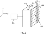
- the transmitting antenna 110 has an transmitting surface 160 of predetermined shape. This antenna would not make it possible to obtain the desired directivity pattern if it were formed from a single transducer or from a plurality of transducers supplied by means of the same signal.
- the antenna 110 is here flat, in other words its emitting surface 160 is flat. As a variant, its emitting surface could be cylindrical or have another shape.
- the curve formed by the emitting surface 160 in a section of the antenna in a plane perpendicular to the longitudinal axis of the antenna is formed by a plurality of transducers 180.
- the profile of the antenna is a formed curve. by a plurality of transducers 180.
- This curve is a straight line in the case of a planar antenna and a portion of a circle or a circle in the case of a cylindrical antenna.
- These transducers 180 form a column C along the z 'axis.
- the transducers 180 of the column of transducers are supplied by a supply device 190.
- This power supply device 190 is configured so as to supply transducers 180 with the same signal assigned to respective delays and / or amplitude modulations chosen so that the antenna 110 has the desired emission pattern as defined above.
- the delays and / or amplitude modulations are chosen so that the antenna 110 has a transmission pattern identical to a curved antenna as described above.
- a planar or cylindrical antenna is easier to manufacture than an antenna with variable curvature according to the first embodiment.
- the antenna can be depointed in bearing, that is to say, in a plane perpendicular to the plane formed by the directions d1 and d2.
- the antenna comprises a plurality of columns of at least one transducer distributed in a direction perpendicular to the plane formed by the directions d1 and d2, it is that is to say in the longitudinal direction of the antenna, and the feed device is configured so as to feed the transducer columns with a signal affected by other respective phase shifts and / or other amplitude modulation depending on the position of the column of transducers in the direction perpendicular to the plane formed by the directions d1 and d2.
- the curve formed by the emitting surface, in a section plane of the antenna perpendicular to its longitudinal axis, is formed by a single transducer.
- the columns C could consist of a plurality of transducers fed by the same signal.
- Variable curvature antennas are economical in the sense that they only require a power supply to power a column of transducers or the single transducer forming the column. The control of these transducers by a single signal or the control of a single transducer so as to form the desired emission pattern is not very complex and efficient.
- the sonar system described above comprises several transmitting antennas but could include only one.
- the antennas are arranged so that the emitting surfaces 6 extend parallel to the direction of movement of the carrier. These are side sonars.
- the sonar system comprises at least one transmitting antenna comprising a transmitting surface perpendicular to the direction of advance of the wearer. This is then a frontal sonar.
- the plane formed by the directions d1 and d2 is the plane (x, z) with the modifications to the arrangement of the transmitting antenna that this implies.
- the antenna is then advantageously arranged so that its longitudinal axis x 'is parallel to the y axis, the z' axis is parallel to the z axis and the y 'axis is parallel to the x axis .
- the invention also relates to a sonar system comprising the carrier and a transmitting antenna according to the invention.
Landscapes
- Engineering & Computer Science (AREA)
- Physics & Mathematics (AREA)
- Radar, Positioning & Navigation (AREA)
- Remote Sensing (AREA)
- Acoustics & Sound (AREA)
- Computer Networks & Wireless Communication (AREA)
- General Physics & Mathematics (AREA)
- Multimedia (AREA)
- Measurement Of Velocity Or Position Using Acoustic Or Ultrasonic Waves (AREA)
- Variable-Direction Aerials And Aerial Arrays (AREA)
Claims (14)
- Sonarsystem zur Abbildung des Meeresbodens, beinhaltend mindestens eine Sendeantenne (10), welche dazu bestimmt ist, einen auf den Meeresboden gerichteten akustischen Strahl auszusenden, welcher einen Nutzwinkelsektor (4) abdeckt, welcher bei der Antenne beginnt und durch eine erste Richtung (d1) und eine zweite Richtung (d2) abgegrenzt ist, welche in Bezug auf die Waagerechte und die Senkrechte geneigt sind, wobei die erste Richtung (d1) einen Winkel mit der Waagerechten (01) bildet, welcher einen Absolutwert unter einem Absolutwert eines zweiten Winkels (02) aufweist, welcher zwischen der zweiten Richtung und der Waagerechten gebildet ist, wobei der Absolutwert des ersten Winkels und der Absolutwert des zweiten Winkels π/2 unterschreiten,
wobei die Sendeantenne (10) dazu konfiguriert ist, ein Emissionsdiagramm zu bilden, welches ein absolutes Maximum an im Wesentlichen in der ersten Richtung (d1) ausgesandter Energie aufweist und eine absteigende ausgesandte Energie von der ersten Richtung (d1) bis zur zweiten Richtung (d2) aufweist,
dadurch gekennzeichnet, dass man einen Abschnitt des Nutzwinkelsektors definiert, welcher durch die zweite Richtung (d2) und eine dritte Richtung (d3) abgegrenzt ist, welche zwischen der ersten Richtung (d1) und der zweiten Richtung (d2) liegt, dadurch, dass man ein ideales Emissionsdiagramm definiert, welches in jeder Richtung des Abschnitts einen Winkel θ mit der Waagerechten bildet,
wobei eine ideale Abschwächung DE (θ) durch folgende Gleichung gegeben ist:
wobei das Emissionsdiagramm in der dritten Richtung (d3) eine Energieabschwächung in Bezug auf die in der ersten Richtung (d1) ausgesandte Energie von im Wesentlichen gleich 3dB aufweist. - Sonarsystem nach dem vorhergehenden Anspruch, wobei die dritte Richtung eine Richtung ist, bei welcher die Abschwächung im Wesentlichen gleich 3 dB ist, wobei der zwischen der dritten Richtung und der ersten Richtung gebildete Winkel unter 3 Grad beträgt.
- Sonarsystem nach einem der vorhergehenden Ansprüche, wobei die Sendeantenne (10) eine Sendefläche (6) beinhaltet, deren Profil, in einer Ebene rechtwinklig zu der durch die erste Richtung d1 und die zweite Richtung d2 gebildeten Ebene, eine Kurve ist, deren Krümmungsradius gemäß der gekrümmten Abszisse auf dieser Kurve variiert, um das Emissionsdiagramm zu bilden.
- Sonarsystem nach dem vorhergehenden Anspruch, wobei die Sendefläche eine gekrümmte Fläche (6) ist.
- Sonarsystem nach einem der Ansprüche 3 bis 4, wobei der Krümmungsradius der Sendefläche mit zunehmendem Abstand zwischen dem betrachteten Punkt der Sendefläche zum idealen Meeresboden in einer zum idealen Meeresboden rechtwinkligen Richtung ansteigt.
- Sonarsystem nach einem der Ansprüche 3 bis 5, wobei die durch die Sendefläche (6) in einer Schnittebene der Antenne rechtwinklig zu ihrer Längsachse gebildeten Kurve durch einen einzigen Umwandler gebildet wird.
- Sonarsystem nach einem der vorhergehenden Ansprüche, bei welchem die Antenne ein einheitliches Profil über die gesamte Länge der Antenne aufweist.
- Sonarsystem nach einem der Ansprüche 1 bis 2, bei welchem die Antenne (110) eine Sendefläche (160) beinhaltet, welche eine Kurve in einer Schnittebene der Antenne rechtwinklig zu ihrer Längsachse bildet, wobei die Kurve durch eine Vielzahl von Umwandlern (180) gebildet wird, wobei die Antenne eine Speisungsvorrichtung (90) beinhaltet, welche die jeweiligen Umwandler mit einem gleichen Signal speist, welches von jeweiligen Phasenverschiebungen und/oder Amplitudenmodulation betroffen ist, um das Emissionsdiagramm zu bilden.
- Sonarsystem nach dem vorhergehenden Anspruch, wobei die Sendefläche (160) eben oder zylindrisch ist.
- Sonarsystem nach einem der vorhergehenden Ansprüche, wobei die Sendeantenne in Peilrichtung versetzbar ist.
- Sonarsystem nach einem der vorhergehenden Ansprüche, beinhaltend einen Träger (2), wobei die Sendeantenne (6) auf dem Träger (2) installiert ist.
- Sonarsystem nach einem der vorhergehenden Ansprüche, wobei die Sendeantenne (6) so angeordnet ist, dass ihre Sendefläche (6) sich in Längsrichtung entlang einer Achse parallel zur Bewegungsrichtung des Trägers (2) erstreckt.
- Sonarsystem nach dem vorhergehenden Anspruch, beinhaltend zwei an Backbord und an Steuerbord des Trägers befestigte Sendeantennen.
- Sonarsystem nach einem der vorhergehenden Ansprüche, wobei die erste Richtung (d1) die Richtung der maximalen Reichweite des Sonarsystems ist und die zweite Richtung (d2) die Richtung der minimalen Reichweite des Sonarsystems ist.
Applications Claiming Priority (2)
| Application Number | Priority Date | Filing Date | Title |
|---|---|---|---|
| FR1301864A FR3009391B1 (fr) | 2013-08-02 | 2013-08-02 | Systeme sonar a antenne courbe ou configuree pour emettre le meme diagramme d'emission que l'antenne courbe |
| PCT/EP2014/065972 WO2015014723A1 (fr) | 2013-08-02 | 2014-07-24 | Systeme sonar a antenne courbe ou configuree pour emettre le meme diagramme d'emission que l'antenne courbe |
Publications (2)
| Publication Number | Publication Date |
|---|---|
| EP3028064A1 EP3028064A1 (de) | 2016-06-08 |
| EP3028064B1 true EP3028064B1 (de) | 2020-09-16 |
Family
ID=50473344
Family Applications (1)
| Application Number | Title | Priority Date | Filing Date |
|---|---|---|---|
| EP14744083.8A Active EP3028064B1 (de) | 2013-08-02 | 2014-07-24 | Sonarsystem mit einer gekrümmten antenne oder einer für die übertragung desselben übertragungsmusters wie die gekrümmte antenne konfigurierten antenne |
Country Status (10)
| Country | Link |
|---|---|
| US (1) | US10061022B2 (de) |
| EP (1) | EP3028064B1 (de) |
| JP (1) | JP6657085B2 (de) |
| KR (1) | KR20160040640A (de) |
| AU (1) | AU2014298630B2 (de) |
| BR (1) | BR112016002014A2 (de) |
| CA (1) | CA2920275C (de) |
| FR (1) | FR3009391B1 (de) |
| SG (1) | SG11201600692VA (de) |
| WO (1) | WO2015014723A1 (de) |
Family Cites Families (15)
| Publication number | Priority date | Publication date | Assignee | Title |
|---|---|---|---|---|
| JPS5634832B2 (de) * | 1973-03-23 | 1981-08-13 | ||
| JPS5020693Y1 (de) * | 1974-07-03 | 1975-06-23 | ||
| US4075599A (en) * | 1976-11-30 | 1978-02-21 | The International Nickel Company, Inc. | Undersea geophysical exploration |
| JPS5919680B2 (ja) | 1979-02-02 | 1984-05-08 | 呉羽化学工業株式会社 | 可変曲率の音波送受信装置 |
| US4802148A (en) * | 1982-11-08 | 1989-01-31 | Westinghouse Electric Corp. | Side-looking sonar apparatus |
| JPS62235585A (ja) | 1986-04-05 | 1987-10-15 | Hitachi Zosen Corp | 可変送受波装置 |
| US5200931A (en) * | 1991-06-18 | 1993-04-06 | Alliant Techsystems Inc. | Volumetric and terrain imaging sonar |
| US5546356A (en) * | 1993-06-30 | 1996-08-13 | The United States Of America As Represented By The Secretary Of The Navy | Wide beam acoustic projector with sharp cutoff and low side lobes |
| FR2827392B1 (fr) * | 2001-07-13 | 2009-01-23 | Thomson Marconi Sonar Sas | Sonar d'imagerie et systeme de detection utilisant un tel sonar |
| US6685641B2 (en) * | 2002-02-01 | 2004-02-03 | Siemens Medical Solutions Usa, Inc. | Plane wave scanning reception and receiver |
| US6868041B2 (en) * | 2002-05-01 | 2005-03-15 | Quester Tangent Corporation | Compensation of sonar image data primarily for seabed classification |
| US8038616B2 (en) * | 2003-05-30 | 2011-10-18 | Surf Technology As | Acoustic imaging by nonlinear low frequency manipulation of high frequency scattering and propagation properties |
| ES2277473B1 (es) * | 2004-01-30 | 2008-07-16 | Consejo Sup. Investig. Cientificas | Composicion coherente de señales por correccion focal progresiva. |
| JP2007298289A (ja) * | 2006-04-27 | 2007-11-15 | Ihi Corp | 水底物体探査方法及び装置 |
| WO2010132974A1 (en) * | 2009-05-20 | 2010-11-25 | Imagenex Technology Corp. | Controlling an image element in a reflected energy measurement system |
-
2013
- 2013-08-02 FR FR1301864A patent/FR3009391B1/fr active Active
-
2014
- 2014-07-24 EP EP14744083.8A patent/EP3028064B1/de active Active
- 2014-07-24 KR KR1020167005502A patent/KR20160040640A/ko not_active Withdrawn
- 2014-07-24 BR BR112016002014A patent/BR112016002014A2/pt not_active IP Right Cessation
- 2014-07-24 CA CA2920275A patent/CA2920275C/en active Active
- 2014-07-24 AU AU2014298630A patent/AU2014298630B2/en active Active
- 2014-07-24 US US14/908,477 patent/US10061022B2/en active Active
- 2014-07-24 JP JP2016530447A patent/JP6657085B2/ja active Active
- 2014-07-24 WO PCT/EP2014/065972 patent/WO2015014723A1/fr not_active Ceased
- 2014-07-24 SG SG11201600692VA patent/SG11201600692VA/en unknown
Non-Patent Citations (1)
| Title |
|---|
| None * |
Also Published As
| Publication number | Publication date |
|---|---|
| AU2014298630A1 (en) | 2016-02-18 |
| JP2016530508A (ja) | 2016-09-29 |
| BR112016002014A2 (pt) | 2017-08-01 |
| US10061022B2 (en) | 2018-08-28 |
| AU2014298630B2 (en) | 2017-08-31 |
| FR3009391B1 (fr) | 2016-11-04 |
| FR3009391A1 (fr) | 2015-02-06 |
| CA2920275C (en) | 2021-06-01 |
| SG11201600692VA (en) | 2016-02-26 |
| WO2015014723A1 (fr) | 2015-02-05 |
| KR20160040640A (ko) | 2016-04-14 |
| US20160170012A1 (en) | 2016-06-16 |
| CA2920275A1 (en) | 2015-02-05 |
| JP6657085B2 (ja) | 2020-03-04 |
| EP3028064A1 (de) | 2016-06-08 |
Similar Documents
| Publication | Publication Date | Title |
|---|---|---|
| EP0070494B1 (de) | Unterseeische Sonareinrichtung | |
| FR3004586A1 (fr) | Radar meteorologique embarque a antenne rotative | |
| FR2729041A1 (fr) | Procede d'emission acoustique pour sonar | |
| WO2018115127A1 (fr) | Systeme optimise de detection acoustique de diverses menaces sous-marines sur une zone sensible | |
| CA3108751A1 (fr) | Piece de carrosserie de vehicule comprenant au moins une antenne directive | |
| EP2010937B1 (de) | Verfahren zum optimieren der stromversorgung für eine linear sendende antenne, die so gezogen wird, dass sie im omnidirektionalen modus sendet | |
| FR2639718A1 (fr) | Radar ultrasonique a visee laterale notamment embarque dans un vehicule sous-marin se deplacant au-dessus d'une surface de visee | |
| EP3027499A1 (de) | Zum schwimmen auf wasser fähiges seeobjekt mit einer einsetzbaren vorrichtung zum senden und/oder empfangen elektromagnetischer wellen | |
| FR3093961A1 (fr) | Pièce de carrosserie de véhicule comprenant au moins une antenne directive | |
| WO2018115125A1 (fr) | Systeme reparti modulaire de detection acoustique des menaces sous-marines sur une zone sensible | |
| EP1407292B1 (de) | Bilderzeugungs- sonar und detektionssytem mit verwendung eines solchen sonars | |
| WO2015014723A1 (fr) | Systeme sonar a antenne courbe ou configuree pour emettre le meme diagramme d'emission que l'antenne courbe | |
| EP0796439A1 (de) | Empfangsverfahren mit mehrdeutigkeitsentfernung für akustische lineare schleppantenne | |
| EP2010938B1 (de) | Mehrstrahl-tonerzeugungsvorrichtung | |
| EP4396608B1 (de) | Vorrichtung und verfahren zur erfassung und ortung von unterwasserobjekten | |
| FR3103571A1 (fr) | Dispositif sonar | |
| EP3871001A1 (de) | Verfahren zur verwendung eines aktiven sonars mit einem breiten spektralen emissionsband und sonarsystem | |
| FR2679041A1 (fr) | Systeme de detection d'objets sous-marins. | |
| EP2401627A1 (de) | Verfahren zum überwachen des beleuchtungsgesetzes einer radarantenne und entsprechende einrichtung | |
| FR2704113A1 (fr) | Antenne hydrophonique panoramique à large bande pour la réception d'ondes acoustiques. |
Legal Events
| Date | Code | Title | Description |
|---|---|---|---|
| PUAI | Public reference made under article 153(3) epc to a published international application that has entered the european phase |
Free format text: ORIGINAL CODE: 0009012 |
|
| 17P | Request for examination filed |
Effective date: 20160111 |
|
| AK | Designated contracting states |
Kind code of ref document: A1 Designated state(s): AL AT BE BG CH CY CZ DE DK EE ES FI FR GB GR HR HU IE IS IT LI LT LU LV MC MK MT NL NO PL PT RO RS SE SI SK SM TR |
|
| AX | Request for extension of the european patent |
Extension state: BA ME |
|
| DAX | Request for extension of the european patent (deleted) | ||
| STAA | Information on the status of an ep patent application or granted ep patent |
Free format text: STATUS: EXAMINATION IS IN PROGRESS |
|
| 17Q | First examination report despatched |
Effective date: 20180927 |
|
| GRAP | Despatch of communication of intention to grant a patent |
Free format text: ORIGINAL CODE: EPIDOSNIGR1 |
|
| STAA | Information on the status of an ep patent application or granted ep patent |
Free format text: STATUS: GRANT OF PATENT IS INTENDED |
|
| INTG | Intention to grant announced |
Effective date: 20200226 |
|
| GRAJ | Information related to disapproval of communication of intention to grant by the applicant or resumption of examination proceedings by the epo deleted |
Free format text: ORIGINAL CODE: EPIDOSDIGR1 |
|
| STAA | Information on the status of an ep patent application or granted ep patent |
Free format text: STATUS: EXAMINATION IS IN PROGRESS |
|
| GRAP | Despatch of communication of intention to grant a patent |
Free format text: ORIGINAL CODE: EPIDOSNIGR1 |
|
| STAA | Information on the status of an ep patent application or granted ep patent |
Free format text: STATUS: GRANT OF PATENT IS INTENDED |
|
| INTC | Intention to grant announced (deleted) | ||
| INTG | Intention to grant announced |
Effective date: 20200506 |
|
| GRAS | Grant fee paid |
Free format text: ORIGINAL CODE: EPIDOSNIGR3 |
|
| GRAA | (expected) grant |
Free format text: ORIGINAL CODE: 0009210 |
|
| STAA | Information on the status of an ep patent application or granted ep patent |
Free format text: STATUS: THE PATENT HAS BEEN GRANTED |
|
| AK | Designated contracting states |
Kind code of ref document: B1 Designated state(s): AL AT BE BG CH CY CZ DE DK EE ES FI FR GB GR HR HU IE IS IT LI LT LU LV MC MK MT NL NO PL PT RO RS SE SI SK SM TR |
|
| REG | Reference to a national code |
Ref country code: GB Ref legal event code: FG4D Free format text: NOT ENGLISH |
|
| REG | Reference to a national code |
Ref country code: CH Ref legal event code: EP |
|
| REG | Reference to a national code |
Ref country code: DE Ref legal event code: R096 Ref document number: 602014070243 Country of ref document: DE |
|
| REG | Reference to a national code |
Ref country code: IE Ref legal event code: FG4D Free format text: LANGUAGE OF EP DOCUMENT: FRENCH |
|
| REG | Reference to a national code |
Ref country code: AT Ref legal event code: REF Ref document number: 1314647 Country of ref document: AT Kind code of ref document: T Effective date: 20201015 |
|
| REG | Reference to a national code |
Ref country code: SE Ref legal event code: TRGR |
|
| PG25 | Lapsed in a contracting state [announced via postgrant information from national office to epo] |
Ref country code: GR Free format text: LAPSE BECAUSE OF FAILURE TO SUBMIT A TRANSLATION OF THE DESCRIPTION OR TO PAY THE FEE WITHIN THE PRESCRIBED TIME-LIMIT Effective date: 20201217 Ref country code: BG Free format text: LAPSE BECAUSE OF FAILURE TO SUBMIT A TRANSLATION OF THE DESCRIPTION OR TO PAY THE FEE WITHIN THE PRESCRIBED TIME-LIMIT Effective date: 20201216 Ref country code: FI Free format text: LAPSE BECAUSE OF FAILURE TO SUBMIT A TRANSLATION OF THE DESCRIPTION OR TO PAY THE FEE WITHIN THE PRESCRIBED TIME-LIMIT Effective date: 20200916 Ref country code: HR Free format text: LAPSE BECAUSE OF FAILURE TO SUBMIT A TRANSLATION OF THE DESCRIPTION OR TO PAY THE FEE WITHIN THE PRESCRIBED TIME-LIMIT Effective date: 20200916 |
|
| REG | Reference to a national code |
Ref country code: AT Ref legal event code: MK05 Ref document number: 1314647 Country of ref document: AT Kind code of ref document: T Effective date: 20200916 Ref country code: NO Ref legal event code: T2 Effective date: 20200916 |
|
| REG | Reference to a national code |
Ref country code: NL Ref legal event code: MP Effective date: 20200916 |
|
| PG25 | Lapsed in a contracting state [announced via postgrant information from national office to epo] |
Ref country code: LV Free format text: LAPSE BECAUSE OF FAILURE TO SUBMIT A TRANSLATION OF THE DESCRIPTION OR TO PAY THE FEE WITHIN THE PRESCRIBED TIME-LIMIT Effective date: 20200916 Ref country code: RS Free format text: LAPSE BECAUSE OF FAILURE TO SUBMIT A TRANSLATION OF THE DESCRIPTION OR TO PAY THE FEE WITHIN THE PRESCRIBED TIME-LIMIT Effective date: 20200916 |
|
| REG | Reference to a national code |
Ref country code: LT Ref legal event code: MG4D |
|
| PG25 | Lapsed in a contracting state [announced via postgrant information from national office to epo] |
Ref country code: EE Free format text: LAPSE BECAUSE OF FAILURE TO SUBMIT A TRANSLATION OF THE DESCRIPTION OR TO PAY THE FEE WITHIN THE PRESCRIBED TIME-LIMIT Effective date: 20200916 Ref country code: CZ Free format text: LAPSE BECAUSE OF FAILURE TO SUBMIT A TRANSLATION OF THE DESCRIPTION OR TO PAY THE FEE WITHIN THE PRESCRIBED TIME-LIMIT Effective date: 20200916 Ref country code: LT Free format text: LAPSE BECAUSE OF FAILURE TO SUBMIT A TRANSLATION OF THE DESCRIPTION OR TO PAY THE FEE WITHIN THE PRESCRIBED TIME-LIMIT Effective date: 20200916 Ref country code: PT Free format text: LAPSE BECAUSE OF FAILURE TO SUBMIT A TRANSLATION OF THE DESCRIPTION OR TO PAY THE FEE WITHIN THE PRESCRIBED TIME-LIMIT Effective date: 20210118 Ref country code: NL Free format text: LAPSE BECAUSE OF FAILURE TO SUBMIT A TRANSLATION OF THE DESCRIPTION OR TO PAY THE FEE WITHIN THE PRESCRIBED TIME-LIMIT Effective date: 20200916 Ref country code: RO Free format text: LAPSE BECAUSE OF FAILURE TO SUBMIT A TRANSLATION OF THE DESCRIPTION OR TO PAY THE FEE WITHIN THE PRESCRIBED TIME-LIMIT Effective date: 20200916 Ref country code: SM Free format text: LAPSE BECAUSE OF FAILURE TO SUBMIT A TRANSLATION OF THE DESCRIPTION OR TO PAY THE FEE WITHIN THE PRESCRIBED TIME-LIMIT Effective date: 20200916 |
|
| PG25 | Lapsed in a contracting state [announced via postgrant information from national office to epo] |
Ref country code: PL Free format text: LAPSE BECAUSE OF FAILURE TO SUBMIT A TRANSLATION OF THE DESCRIPTION OR TO PAY THE FEE WITHIN THE PRESCRIBED TIME-LIMIT Effective date: 20200916 Ref country code: IS Free format text: LAPSE BECAUSE OF FAILURE TO SUBMIT A TRANSLATION OF THE DESCRIPTION OR TO PAY THE FEE WITHIN THE PRESCRIBED TIME-LIMIT Effective date: 20210116 Ref country code: AT Free format text: LAPSE BECAUSE OF FAILURE TO SUBMIT A TRANSLATION OF THE DESCRIPTION OR TO PAY THE FEE WITHIN THE PRESCRIBED TIME-LIMIT Effective date: 20200916 Ref country code: AL Free format text: LAPSE BECAUSE OF FAILURE TO SUBMIT A TRANSLATION OF THE DESCRIPTION OR TO PAY THE FEE WITHIN THE PRESCRIBED TIME-LIMIT Effective date: 20200916 Ref country code: ES Free format text: LAPSE BECAUSE OF FAILURE TO SUBMIT A TRANSLATION OF THE DESCRIPTION OR TO PAY THE FEE WITHIN THE PRESCRIBED TIME-LIMIT Effective date: 20200916 |
|
| REG | Reference to a national code |
Ref country code: DE Ref legal event code: R097 Ref document number: 602014070243 Country of ref document: DE |
|
| PG25 | Lapsed in a contracting state [announced via postgrant information from national office to epo] |
Ref country code: SK Free format text: LAPSE BECAUSE OF FAILURE TO SUBMIT A TRANSLATION OF THE DESCRIPTION OR TO PAY THE FEE WITHIN THE PRESCRIBED TIME-LIMIT Effective date: 20200916 |
|
| PLBE | No opposition filed within time limit |
Free format text: ORIGINAL CODE: 0009261 |
|
| STAA | Information on the status of an ep patent application or granted ep patent |
Free format text: STATUS: NO OPPOSITION FILED WITHIN TIME LIMIT |
|
| 26N | No opposition filed |
Effective date: 20210617 |
|
| PG25 | Lapsed in a contracting state [announced via postgrant information from national office to epo] |
Ref country code: SI Free format text: LAPSE BECAUSE OF FAILURE TO SUBMIT A TRANSLATION OF THE DESCRIPTION OR TO PAY THE FEE WITHIN THE PRESCRIBED TIME-LIMIT Effective date: 20200916 Ref country code: DK Free format text: LAPSE BECAUSE OF FAILURE TO SUBMIT A TRANSLATION OF THE DESCRIPTION OR TO PAY THE FEE WITHIN THE PRESCRIBED TIME-LIMIT Effective date: 20200916 |
|
| PG25 | Lapsed in a contracting state [announced via postgrant information from national office to epo] |
Ref country code: IT Free format text: LAPSE BECAUSE OF FAILURE TO SUBMIT A TRANSLATION OF THE DESCRIPTION OR TO PAY THE FEE WITHIN THE PRESCRIBED TIME-LIMIT Effective date: 20200916 |
|
| REG | Reference to a national code |
Ref country code: CH Ref legal event code: PL |
|
| PG25 | Lapsed in a contracting state [announced via postgrant information from national office to epo] |
Ref country code: MC Free format text: LAPSE BECAUSE OF FAILURE TO SUBMIT A TRANSLATION OF THE DESCRIPTION OR TO PAY THE FEE WITHIN THE PRESCRIBED TIME-LIMIT Effective date: 20200916 |
|
| PG25 | Lapsed in a contracting state [announced via postgrant information from national office to epo] |
Ref country code: LI Free format text: LAPSE BECAUSE OF NON-PAYMENT OF DUE FEES Effective date: 20210731 Ref country code: CH Free format text: LAPSE BECAUSE OF NON-PAYMENT OF DUE FEES Effective date: 20210731 |
|
| PG25 | Lapsed in a contracting state [announced via postgrant information from national office to epo] |
Ref country code: LU Free format text: LAPSE BECAUSE OF NON-PAYMENT OF DUE FEES Effective date: 20210724 |
|
| PG25 | Lapsed in a contracting state [announced via postgrant information from national office to epo] |
Ref country code: IE Free format text: LAPSE BECAUSE OF NON-PAYMENT OF DUE FEES Effective date: 20210724 |
|
| PG25 | Lapsed in a contracting state [announced via postgrant information from national office to epo] |
Ref country code: HU Free format text: LAPSE BECAUSE OF FAILURE TO SUBMIT A TRANSLATION OF THE DESCRIPTION OR TO PAY THE FEE WITHIN THE PRESCRIBED TIME-LIMIT; INVALID AB INITIO Effective date: 20140724 |
|
| PG25 | Lapsed in a contracting state [announced via postgrant information from national office to epo] |
Ref country code: CY Free format text: LAPSE BECAUSE OF FAILURE TO SUBMIT A TRANSLATION OF THE DESCRIPTION OR TO PAY THE FEE WITHIN THE PRESCRIBED TIME-LIMIT Effective date: 20200916 |
|
| P01 | Opt-out of the competence of the unified patent court (upc) registered |
Effective date: 20230606 |
|
| PG25 | Lapsed in a contracting state [announced via postgrant information from national office to epo] |
Ref country code: MK Free format text: LAPSE BECAUSE OF FAILURE TO SUBMIT A TRANSLATION OF THE DESCRIPTION OR TO PAY THE FEE WITHIN THE PRESCRIBED TIME-LIMIT Effective date: 20200916 |
|
| PG25 | Lapsed in a contracting state [announced via postgrant information from national office to epo] |
Ref country code: TR Free format text: LAPSE BECAUSE OF FAILURE TO SUBMIT A TRANSLATION OF THE DESCRIPTION OR TO PAY THE FEE WITHIN THE PRESCRIBED TIME-LIMIT Effective date: 20200916 |
|
| PG25 | Lapsed in a contracting state [announced via postgrant information from national office to epo] |
Ref country code: MT Free format text: LAPSE BECAUSE OF FAILURE TO SUBMIT A TRANSLATION OF THE DESCRIPTION OR TO PAY THE FEE WITHIN THE PRESCRIBED TIME-LIMIT Effective date: 20200916 |
|
| PGFP | Annual fee paid to national office [announced via postgrant information from national office to epo] |
Ref country code: GB Payment date: 20250619 Year of fee payment: 12 |
|
| PGFP | Annual fee paid to national office [announced via postgrant information from national office to epo] |
Ref country code: BE Payment date: 20250619 Year of fee payment: 12 |
|
| PGFP | Annual fee paid to national office [announced via postgrant information from national office to epo] |
Ref country code: FR Payment date: 20250623 Year of fee payment: 12 |
|
| PGFP | Annual fee paid to national office [announced via postgrant information from national office to epo] |
Ref country code: SE Payment date: 20250626 Year of fee payment: 12 |
|
| PGFP | Annual fee paid to national office [announced via postgrant information from national office to epo] |
Ref country code: DE Payment date: 20250618 Year of fee payment: 12 |
|
| PGFP | Annual fee paid to national office [announced via postgrant information from national office to epo] |
Ref country code: NO Payment date: 20250709 Year of fee payment: 12 |