EP3027871B1 - Gearbox and disassembly method for disengaging a drive shaft in such a gearbox - Google Patents
Gearbox and disassembly method for disengaging a drive shaft in such a gearbox Download PDFInfo
- Publication number
- EP3027871B1 EP3027871B1 EP14759330.5A EP14759330A EP3027871B1 EP 3027871 B1 EP3027871 B1 EP 3027871B1 EP 14759330 A EP14759330 A EP 14759330A EP 3027871 B1 EP3027871 B1 EP 3027871B1
- Authority
- EP
- European Patent Office
- Prior art keywords
- axial
- drive shaft
- axially
- shaft
- shoulder
- Prior art date
- Legal status (The legal status is an assumption and is not a legal conclusion. Google has not performed a legal analysis and makes no representation as to the accuracy of the status listed.)
- Active
Links
Images


Classifications
-
- F—MECHANICAL ENGINEERING; LIGHTING; HEATING; WEAPONS; BLASTING
- F16—ENGINEERING ELEMENTS AND UNITS; GENERAL MEASURES FOR PRODUCING AND MAINTAINING EFFECTIVE FUNCTIONING OF MACHINES OR INSTALLATIONS; THERMAL INSULATION IN GENERAL
- F16D—COUPLINGS FOR TRANSMITTING ROTATION; CLUTCHES; BRAKES
- F16D1/00—Couplings for rigidly connecting two coaxial shafts or other movable machine elements
- F16D1/10—Quick-acting couplings in which the parts are connected by simply bringing them together axially
- F16D1/108—Quick-acting couplings in which the parts are connected by simply bringing them together axially having retaining means rotating with the coupling and acting by interengaging parts, i.e. positive coupling
-
- F—MECHANICAL ENGINEERING; LIGHTING; HEATING; WEAPONS; BLASTING
- F02—COMBUSTION ENGINES; HOT-GAS OR COMBUSTION-PRODUCT ENGINE PLANTS
- F02C—GAS-TURBINE PLANTS; AIR INTAKES FOR JET-PROPULSION PLANTS; CONTROLLING FUEL SUPPLY IN AIR-BREATHING JET-PROPULSION PLANTS
- F02C7/00—Features, components parts, details or accessories, not provided for in, or of interest apart form groups F02C1/00 - F02C6/00; Air intakes for jet-propulsion plants
- F02C7/32—Arrangement, mounting, or driving, of auxiliaries
-
- F—MECHANICAL ENGINEERING; LIGHTING; HEATING; WEAPONS; BLASTING
- F16—ENGINEERING ELEMENTS AND UNITS; GENERAL MEASURES FOR PRODUCING AND MAINTAINING EFFECTIVE FUNCTIONING OF MACHINES OR INSTALLATIONS; THERMAL INSULATION IN GENERAL
- F16D—COUPLINGS FOR TRANSMITTING ROTATION; CLUTCHES; BRAKES
- F16D1/00—Couplings for rigidly connecting two coaxial shafts or other movable machine elements
- F16D1/06—Couplings for rigidly connecting two coaxial shafts or other movable machine elements for attachment of a member on a shaft or on a shaft-end
- F16D1/08—Couplings for rigidly connecting two coaxial shafts or other movable machine elements for attachment of a member on a shaft or on a shaft-end with clamping hub; with hub and longitudinal key
- F16D1/0876—Couplings for rigidly connecting two coaxial shafts or other movable machine elements for attachment of a member on a shaft or on a shaft-end with clamping hub; with hub and longitudinal key with axial keys and no other radial clamping
-
- F—MECHANICAL ENGINEERING; LIGHTING; HEATING; WEAPONS; BLASTING
- F16—ENGINEERING ELEMENTS AND UNITS; GENERAL MEASURES FOR PRODUCING AND MAINTAINING EFFECTIVE FUNCTIONING OF MACHINES OR INSTALLATIONS; THERMAL INSULATION IN GENERAL
- F16D—COUPLINGS FOR TRANSMITTING ROTATION; CLUTCHES; BRAKES
- F16D1/00—Couplings for rigidly connecting two coaxial shafts or other movable machine elements
- F16D1/10—Quick-acting couplings in which the parts are connected by simply bringing them together axially
-
- F—MECHANICAL ENGINEERING; LIGHTING; HEATING; WEAPONS; BLASTING
- F16—ENGINEERING ELEMENTS AND UNITS; GENERAL MEASURES FOR PRODUCING AND MAINTAINING EFFECTIVE FUNCTIONING OF MACHINES OR INSTALLATIONS; THERMAL INSULATION IN GENERAL
- F16H—GEARING
- F16H1/00—Toothed gearings for conveying rotary motion
- F16H1/02—Toothed gearings for conveying rotary motion without gears having orbital motion
- F16H1/04—Toothed gearings for conveying rotary motion without gears having orbital motion involving only two intermeshing members
- F16H1/12—Toothed gearings for conveying rotary motion without gears having orbital motion involving only two intermeshing members with non-parallel axes
- F16H1/14—Toothed gearings for conveying rotary motion without gears having orbital motion involving only two intermeshing members with non-parallel axes comprising conical gears only
-
- F—MECHANICAL ENGINEERING; LIGHTING; HEATING; WEAPONS; BLASTING
- F05—INDEXING SCHEMES RELATING TO ENGINES OR PUMPS IN VARIOUS SUBCLASSES OF CLASSES F01-F04
- F05D—INDEXING SCHEME FOR ASPECTS RELATING TO NON-POSITIVE-DISPLACEMENT MACHINES OR ENGINES, GAS-TURBINES OR JET-PROPULSION PLANTS
- F05D2230/00—Manufacture
- F05D2230/70—Disassembly methods
Definitions
- the present invention relates to a gearbox, in particular for turbofan jet engines in aeronautic applications.
- Some engines of such a type have a gearbox comprising a secondary unit, of the bevel gear type, for transferring the motion between two inclined axes; and a main unit, which is connected to the secondary unit by means of a drive shaft.
- a drive shaft which is connected to the secondary unit by means of a drive shaft.
- the ends of such a drive shaft are coupled, respectively, to hollow shafts belonging to the two aforesaid units.
- the hollow shaft of the main unit actuates an accessory assembly, arranged on the axial end opposite to the one into which the drive shaft is inserted.
- the main unit is axially interposed between the accessory assembly and the drive shaft.
- the gearbox is disassembled so as to be able to remove and/or treat the two units separately. Therefore, during disassembly, the drive shaft must be disengaged from the secondary unit.
- the drive shaft is axially extracted through the hollow shaft of the main unit, operating from the accessory assembly side, after having disengaged and removed the latter from the main unit.
- the drive shaft in other turbofan jet engines is constituted by three or more pieces, which are fixed to one another, e.g. by means of bolts, which may be disengaged to disassemble and remove the drive shaft without need to remove the latter axially through the main unit.
- the fact of making the drive shaft in several pieces complicates the making and assembly and the drive shaft itself. Therefore this type of solution is not very satisfactory.
- the drive shaft comprises a splined portion which engages the hollow shaft of the main unit and is arranged in axial abutment against a ring arranged in a groove of such a hollow shaft. In use, such a ring prevents the drive shaft from being extracted from the hollow shaft of the main unit.
- the ring can be accessed to be removed.
- the drive shaft is extracted from the hollow shaft of the main unit and remains coupled to the secondary unit only.
- a gearbox is provided, as disclosed in claim 1.
- a disassembly method for disengaging a drive shaft in such a gearbox is also provided, as disclosed in claim 13.
- reference numeral 1 indicates, as a whole, a gearbox (shown partially and in simplified manner), in particular for a turbofan jet engine in aeronautic applications.
- the gearbox 1 comprises a module or unit 2, generally indicated as “transfer gearbox” and comprising, in turn, a casing 3 and a gear transmission 4, which transmits motion between two inclined axes 5,6, i.e. which define an angle of less than 180° between each other.
- the transmission 4 is preferably defined by two bevel gears 7,8 which mesh each other.
- the casing 3 is preferably constituted by several pieces fixed to one another, and houses the transmission 4 and two shafts 9,10, which are supported by the casing 3 in known manner by means of rolling bearings.
- the shaft 9 extends along axis 5, defines a motion inlet, and supports the gear 7 in fixed position at an axial end thereof.
- the gear 8 is made in only one piece with the portion 11.
- the shaft 10 ends on the end opposite to portion 11 with a portion 12, which defines an axial mouth 16 of the shaft 10, has a clutch, radially inwards, preferably defined by a hole spline 13, and is joined to the portion 11 by means of an intermediate portion 14.
- the shaft 10 comprises an inner projection 18, preferably defined by an annular flange, which radially projects from the portion 14 and has a function which will be described below.
- the gearbox 1 comprises a module or unit 22 (partially shown) generally indicated as “accessory gearbox”, and comprising, in turn, a casing 23 and a shaft 24, which extends along axis 6 within the casing 23, is axially hollow and is connected to the shaft 10 by means of a coaxial drive shaft 25.
- the shaft 24 defines a motion inlet for a gear transmission 28 of the unit 22.
- the accompanying figures show only one of the transmission gears 28, i.e. a gear which is indicated by reference numeral 29 and which is fitted onto shaft 24.
- the unit 22 is axially arranged between the shaft 25 and an accessory assembly (not shown), which is fixed to the casing 23 and is actuated (in manner not shown) either by the transmission 28 or by the shaft 24.
- the shaft 24 axially ends, towards the accessory assembly, with a portion 31 and, towards the unit 2, with a portion 32, and comprises an intermediate portion 33 which has a clutch, radially inwards, also preferably defined by a hole spline 34.
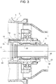
- the hole splines 13 and 34 are engaged in an angularly fixed and axially slidable manner by shaft splines, defined by a portion 35 ( fig. 3 ) and by a portion 36 ( fig. 2 ) of the shaft 25, respectively.
- the portion 32 is radially delimited by an external threaded surface 40 and by an inner surface 41, which extends starting from an axial end face 43 of the shaft 24 and is shaped so as to lock a ring 44 which is at least partially housed in the portion 32 in angular manner.
- the surface 41 comprises a cylindrical zone 45 and at least one radial notch 46, which axially extends starting from the face 43.
- the ring 44 is coaxial to the shafts 24 and 25, axially rests against the portion 32 and comprises an annular wall 48, coupled to the surface 41 in an angularly fixed and axially sliding manner.
- the wall 48 has an external cylindrical surface 49, which is substantially complementary with the zone 45, and comprises at least one radial tooth 50, which projects outwards from the surface 49 and engages the notch 46 for keeping the ring 44 angularly locked.
- the number of the notches 46 and of the teeth 50 may be higher.
- different solutions may be provided for the angular locking, e.g. respective flattenings on the surfaces 41 and 49.
- the ring 44 further comprises an external flange 52, which projects from an axial edge of the wall 48 and has an external diameter which is greater than the internal diameter of the face 43.
- the function of the flange 52 is to go against the face 43, and thus prevent the insertion of the ring 44 in the portion 32 if the ring 44 is fitted back to front on the shaft 25 by mistake during the assembly operations of the gearbox 1.
- the ring 44 further comprises an axial shoulder 53, which is arranged on the opposite axial end of the flange 52, and is advantageously defined by a hole spline or by an inner axial toothing 54, as shown in figure 5 and as will be described hereinafter.
- the toothing 54 surrounds an intermediate portion 55 of the shaft 25 with radial clearance: in other words, the internal diameter of the axial shoulder 53 is greater than the external diameter of the portion 55.
- the portion 55 is preferably cylindrical and axially joins the portion 36 to an external radial projection of the shaft 25, advantageously defined by an axial toothing 56.
- the toothing 56 is identical and aligned with a shaft spline of the portion 36, so as to make both at the same time with the same method.
- the toothing 56 projects from the portion 55 so as to reach an external diameter which is greater than the internal diameter of the shoulder 53, therefore the latter prevents the toothing 56 and, thus, the shaft 25, from translating axially towards the inside of the shaft 24.
- the profiles in circumferential direction of the toothing 56 and of the shoulder 53 are shaped so as to be able to slide along axis 6 by the side of each other without interference after a relative rotation, i.e. after a rotation of the ring 44 with respect to the shaft 25.
- the profile of the toothing 54, in circumferential direction is complementary with that of the toothing 56, but rotated by an amount substantially equal to half of the angular pitch between two consecutive teeth.
- the device 57 further comprises an axial locking element 60, which is fixed to the portion 32 in releasable manner and comprises a portion 61 which keeps the ring 40 engaged in the portion 32 in fixed axial position.
- the locking element 60 is defined by a ring nut which is fitted with slight radial clearance about the shaft 25 and is screwed onto the surface 40.
- the portion 61 is defined by an inner flange arranged on an axial end of the ring nut 60.
- the ring nut 60 has one or more radial holes 63 engaged by dowels (not shown), having an end engaging the portion 32 to perform an anti-loosening function on the ring nut 60.
- the shaft 25 is axially locked with respect to the shaft 24 only one-way, because it is free to translate towards the unit 2.
- the shaft 25 has an end 64 which is axially spaced from the flange 18 and has an external diameter which is greater than the internal diameter of the flange 18.
- the latter defines a limit stop shoulder for the axial translation of the shaft 25.
- the shaft 25 comprises an intermediate portion 65, which axially joins the portion 35 to the toothing 56, substantially has the same external diameter as the portion 55 and carries an external projection 66.
- the projection 66 projects from the portion 65 so as to reach a diameter which is greater than the internal diameter of the portion 32, and has an axial position such to impede an incorrect back to front assembly of the shaft 25 (i.e. with the end 64 inserted in the shaft 24) during the assembly of the gearbox 1.
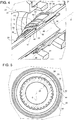
- the portion 65 of the shaft 25, the device 57 and the axial mouth 16 of the shaft 10 remain enclosed by an annular shell 70, which joins the casings 3 and 23, is either openable or removable so as to obtain at least an opening which is axially located between the casings 3 and 23 and can provide access to the device 57 for releasing the shaft 25 from the unit 2 during a disassembly procedure of the gearbox 1.
- the shell 70 is of the telescopic type, because it comprises two sleeves 72,73, which are substantially coaxial to the shaft 25, are fixed in releasable manner to the casings 3 and 23, respectively, and are coupled to each other in axially sliding manner.
- the sleeves 72,73 define respective doors, which are axially sliding to define an opening 74 with respect to the casing 3 ( fig. 7 ) and an opening 75 with respect to the casing 23 ( fig. 6 ), respectively.
- the sleeve 73 is disengaged from the casing 23 and then translated towards the unit 2 so as to form the opening 75 in the disassembly procedure, in order to release the shaft 25 from the unit 2.
- the device 57 is released by means of the following operations by manually operating through the opening 75:
- the opening 75 is closed and the sleeve 73 is fixed to the casing 23 again.
- the opening 74 is then formed by disengaging the sleeve 72 from the casing 3 and moving it axially away.
- the shaft 25 is translated towards the unit 22, i.e. into the hollow shaft 24, so as to release the shaft 25 from the hole spline 13 of the shaft 10.
- the unit 2 is completely separated from the unit 22 and thus may be disengaged and removed, e.g. by means of a translation along axis 5, without interference with the unit 22 or with the shaft 25, while the shaft 25 remains coupled to the unit 22.
- the configuration of the gearbox 1 and, especially, the position of the device 57 allow to release the shaft 25 from the unit 2 without need to remove the accessory assembly and without requiring clearance to operate on the unit 22 from the side of the portion 31, because all the operations are carried out through the clearance which is axially available between the casings 3 and 23.
- the shaft 25 is disassembled without need to be disassembled into several pieces, because it is simply made to slide along the axis 6, first in one direction to generate a sufficient clearance to disengage the shoulder 53, and then in the opposite direction to remove the shaft 25 from the unit 2 in effective manner.
- the disassembly also requires relatively short times for releasing the shaft 25.
- there are no bolts or screws to be unscrewed except for the ring nut 60
- there are no connection elements which need to be completely removed indeed, the ring nut 60 and the ring 44, even after having been disengaged from the portion 32, remain supported by the portion 65, as shown in figure 7 , without the risk of loosing them in the shell 70 or in the casings 3,23)
- the shaft 25 does not need to be disassembled into several pieces.
- the features of the device 57 make the axial retention of the shaft 25 stable and safe, even if only one-way. At the same time, the features of the device 57 allow to have a relatively low number of pieces with respect to the known solutions and thus to have a high simplicity and a high reliability.
- the device 57 could be arranged at the mouth 16, instead of at the portion 32, so as to release the shaft 25 from the unit 22 and insert it in the shaft 10. This solution is preferable when the unit 22 is the one which is normally removed, while the shaft 25 remains coupled to the unit 2.
- a two-way locking system may be provided (e.g. with a possible appendix of the ring nut 60 to lock possible axial displacements of the toothing 56 towards the unit 2), instead of a one-way system; and/or the ring nut 60 could be replaced by another axial locking element (e.g. by an element fitted in radial direction on the portion 32 or a bayonet-coupled element).
- shaft and hole splines provided between the shaft 25 and shafts 10,24 could be replaced by other coupling systems which allow an angular constraint and axial sliding freedom in all cases.
- gearbox 1 could also be used for naval applications, instead of aeronautical applications.
Landscapes
- Engineering & Computer Science (AREA)
- General Engineering & Computer Science (AREA)
- Mechanical Engineering (AREA)
- Chemical & Material Sciences (AREA)
- Combustion & Propulsion (AREA)
- General Details Of Gearings (AREA)
- Structure Of Transmissions (AREA)
- Refuse Collection And Transfer (AREA)
Applications Claiming Priority (2)
| Application Number | Priority Date | Filing Date | Title |
|---|---|---|---|
| IT000636A ITTO20130636A1 (it) | 2013-07-29 | 2013-07-29 | Scatola di trasmissione, e metodo di smontaggio per disaccoppiare un albero di azionamento in tale scatola di trasmissione |
| PCT/IB2014/063526 WO2015015425A1 (en) | 2013-07-29 | 2014-07-29 | Gearbox and disassembly method for disengaging a drive shaft in such a gearbox |
Publications (2)
| Publication Number | Publication Date |
|---|---|
| EP3027871A1 EP3027871A1 (en) | 2016-06-08 |
| EP3027871B1 true EP3027871B1 (en) | 2017-04-26 |
Family
ID=49447719
Family Applications (1)
| Application Number | Title | Priority Date | Filing Date |
|---|---|---|---|
| EP14759330.5A Active EP3027871B1 (en) | 2013-07-29 | 2014-07-29 | Gearbox and disassembly method for disengaging a drive shaft in such a gearbox |
Country Status (9)
| Country | Link |
|---|---|
| US (2) | US10837496B2 (pl) |
| EP (1) | EP3027871B1 (pl) |
| JP (1) | JP6345778B2 (pl) |
| CN (1) | CN105556098B (pl) |
| CA (1) | CA2919231A1 (pl) |
| IT (1) | ITTO20130636A1 (pl) |
| PL (1) | PL3027871T3 (pl) |
| RU (1) | RU2658254C2 (pl) |
| WO (1) | WO2015015425A1 (pl) |
Families Citing this family (11)
| Publication number | Priority date | Publication date | Assignee | Title |
|---|---|---|---|---|
| EP3431811B1 (en) * | 2017-07-21 | 2021-12-22 | Ge Avio S.r.l. | Transmission device for splitting torque between two coaxial gears, in particular for a planetary gearing for aeronautic applications, and method for manufacturing and assembling said transmission device |
| CN110107667B (zh) * | 2019-04-28 | 2021-05-07 | 中国航发湖南动力机械研究所 | 涡轮发动机附件传动机构及其使用方法和涡轮发动机 |
| CN110273999A (zh) * | 2019-05-28 | 2019-09-24 | 淮南巧天机械设备技术有限公司 | 一种变速箱主动圆锥齿轮轴 |
| CN110566632A (zh) * | 2019-08-05 | 2019-12-13 | 厦门丰泰国际新能源汽车有限公司 | 发动机、变速箱和角传动器的总成结构 |
| US11241775B2 (en) | 2019-08-09 | 2022-02-08 | Raytheon Technologies Corporation | Apparatuses and methods for removing a component |
| CN112049902B (zh) * | 2020-09-07 | 2022-11-15 | 中国航发贵阳发动机设计研究所 | 一种可分离式的手传动装置 |
| US11401870B2 (en) | 2020-09-16 | 2022-08-02 | Pratt & Whitney Canada Corp. | Coupling and associated method of transferring torque |
| US11767885B2 (en) | 2021-05-14 | 2023-09-26 | Pratt & Whitney Canada Corp. | Torque transfer coupling |
| US11529705B1 (en) | 2021-06-02 | 2022-12-20 | Pratt & Whitney Canada Corp. | Torque transfer coupling and tool for assembly thereof |
| US12173659B2 (en) | 2023-04-20 | 2024-12-24 | Pratt & Whitney Canada Corp. | Coupling and associated method of transferring torque |
| CN120444140A (zh) | 2024-02-08 | 2025-08-08 | 通用电气阿维奥有限责任公司 | 用于涡轮发动机的齿轮箱组件 |
Family Cites Families (18)
| Publication number | Priority date | Publication date | Assignee | Title |
|---|---|---|---|---|
| US540935A (en) * | 1895-06-11 | a tpitc ip a t | ||
| US3631735A (en) * | 1970-07-02 | 1972-01-04 | Gen Electric | Gas turbine engine gearboxes |
| US3688560A (en) * | 1971-01-29 | 1972-09-05 | Gen Electric | Gas turbine engine with improved auxiliary power take-off |
| US4566296A (en) | 1984-08-06 | 1986-01-28 | Kochakis Donald G | Padlock security cover |
| US5003685A (en) * | 1986-08-12 | 1991-04-02 | Dayco Products-Eaglemotive, Inc. | Method of making a clutch for a cooling fan of a motor vehicle |
| US6058791A (en) * | 1998-03-19 | 2000-05-09 | Alliedsignal, Inc. | Accessory mechanical drive for a gas turbine engine |
| FR2824362B1 (fr) * | 2001-05-03 | 2003-09-05 | Snecma Moteurs | Agencement de montage de deux lignes d'arbre coaxiales |
| FR2826052B1 (fr) * | 2001-06-19 | 2003-12-19 | Snecma Moteurs | Dispositif de secours au rallumage d'un turboreacteur en autorotation |
| US6669393B2 (en) * | 2001-10-10 | 2003-12-30 | General Electric Co. | Connector assembly for gas turbine engines |
| US7386983B2 (en) * | 2004-02-25 | 2008-06-17 | United Technologies Corporation | Apparatus for driving an accessory gearbox in a gas turbine engine |
| FR2882096B1 (fr) * | 2005-02-11 | 2012-04-20 | Snecma Moteurs | Turbomoteur a double corps avec des moyens de prise de mouvement sur les rotors basse pression et haute pression, module de prise de mouvement pour le turbomoteur et procede de montage du turbomoteur |
| RU2302541C2 (ru) | 2005-09-26 | 2007-07-10 | Открытое акционерное общество "Авиадвигатель" | Устройство передачи крутящего момента от вала компрессора к коробке приводных агрегатов газотурбинного двигателя |
| US8257286B2 (en) * | 2006-09-21 | 2012-09-04 | Tyco Healthcare Group Lp | Safety connector apparatus |
| US8015828B2 (en) * | 2007-04-03 | 2011-09-13 | General Electric Company | Power take-off system and gas turbine engine assembly including same |
| US20120251234A1 (en) * | 2011-03-31 | 2012-10-04 | Lemmers Jr Glenn C | Connection device for drive assembly |
| FR2989140B1 (fr) * | 2012-04-06 | 2014-09-05 | Snecma | Systeme de transmission de puissance pour une turbomachine |
| FR3022301B1 (fr) * | 2014-06-12 | 2016-07-29 | Snecma | Turbomachine comprenant un systeme d'entrainement d'un equipement tel qu'un boitier d'accessoires |
| GB201420105D0 (en) * | 2014-11-12 | 2014-12-24 | Rolls Royce Plc | Gas turbine electrical machine arrangement |
-
2013
- 2013-07-29 IT IT000636A patent/ITTO20130636A1/it unknown
-
2014
- 2014-07-29 EP EP14759330.5A patent/EP3027871B1/en active Active
- 2014-07-29 WO PCT/IB2014/063526 patent/WO2015015425A1/en not_active Ceased
- 2014-07-29 JP JP2016530650A patent/JP6345778B2/ja not_active Expired - Fee Related
- 2014-07-29 US US14/908,508 patent/US10837496B2/en active Active
- 2014-07-29 RU RU2016106716A patent/RU2658254C2/ru not_active IP Right Cessation
- 2014-07-29 PL PL14759330T patent/PL3027871T3/pl unknown
- 2014-07-29 CN CN201480043296.3A patent/CN105556098B/zh active Active
- 2014-07-29 CA CA2919231A patent/CA2919231A1/en not_active Abandoned
-
2020
- 2020-10-20 US US17/074,906 patent/US11555521B2/en active Active
Non-Patent Citations (1)
| Title |
|---|
| None * |
Also Published As
| Publication number | Publication date |
|---|---|
| US20210071717A1 (en) | 2021-03-11 |
| RU2016106716A3 (pl) | 2018-04-03 |
| RU2658254C2 (ru) | 2018-06-19 |
| CN105556098B (zh) | 2017-08-22 |
| CN105556098A (zh) | 2016-05-04 |
| PL3027871T3 (pl) | 2017-09-29 |
| EP3027871A1 (en) | 2016-06-08 |
| US20160169289A1 (en) | 2016-06-16 |
| JP6345778B2 (ja) | 2018-06-20 |
| WO2015015425A1 (en) | 2015-02-05 |
| US10837496B2 (en) | 2020-11-17 |
| CA2919231A1 (en) | 2015-02-05 |
| RU2016106716A (ru) | 2017-09-04 |
| JP2016527455A (ja) | 2016-09-08 |
| ITTO20130636A1 (it) | 2015-01-30 |
| US11555521B2 (en) | 2023-01-17 |
Similar Documents
| Publication | Publication Date | Title |
|---|---|---|
| US11555521B2 (en) | Gearbox and disassembly method for disengaging a drive shaft in such a gearbox | |
| DK2908042T3 (en) | Bayonet coupling for detachable connection of pipelines | |
| US5667330A (en) | Quick-connect mechanism for releasably retaining a power take-off shaft within an output shaft hub | |
| US4502583A (en) | Drive unit comprising a motor, a clutch and a gear box with a snap connection in the clutch release system | |
| US2785550A (en) | Rotary drive-transmitting coupling arrangements | |
| US3997962A (en) | Method and tool for removing turbine from gas turbine twin spool engine | |
| US8845275B2 (en) | Cranking pad interlock | |
| US5090263A (en) | Gear coupler | |
| US20230417192A1 (en) | Modularity of an aircraft turbomachine | |
| US9334988B2 (en) | Telescoping pipe connector | |
| EP3187414B1 (en) | Oil transfer assembly for supplying oil into a rotating and translating tube | |
| EP3882447A1 (en) | Decoupler for engine starter | |
| US10421537B2 (en) | Locking mechanisms for tail rotor drive disconnect couplings | |
| EP3059388B1 (en) | Modular components for gas turbine engines | |
| CA2851133C (en) | Telescoping pipe connector | |
| US2836041A (en) | Locking means for parts having threaded engagement | |
| EP2602442B1 (en) | Cranking pad interlock | |
| EP4563837A1 (en) | Pressure retaining cap with manual interface for rotation | |
| EP4563836A1 (en) | Positive locking pistons and manual actuation of mechanical decoupler system | |
| GB1128110A (en) | Improvements relating to shaft couplings for gas turbine engines | |
| US20240003303A1 (en) | Modularity of an aircraft turbomachine |
Legal Events
| Date | Code | Title | Description |
|---|---|---|---|
| PUAI | Public reference made under article 153(3) epc to a published international application that has entered the european phase |
Free format text: ORIGINAL CODE: 0009012 |
|
| 17P | Request for examination filed |
Effective date: 20160122 |
|
| AK | Designated contracting states |
Kind code of ref document: A1 Designated state(s): AL AT BE BG CH CY CZ DE DK EE ES FI FR GB GR HR HU IE IS IT LI LT LU LV MC MK MT NL NO PL PT RO RS SE SI SK SM TR |
|
| AX | Request for extension of the european patent |
Extension state: BA ME |
|
| REG | Reference to a national code |
Ref country code: DE Ref legal event code: R079 Ref document number: 602014009111 Country of ref document: DE Free format text: PREVIOUS MAIN CLASS: F02C0007320000 Ipc: F16D0001080000 |
|
| DAX | Request for extension of the european patent (deleted) | ||
| GRAP | Despatch of communication of intention to grant a patent |
Free format text: ORIGINAL CODE: EPIDOSNIGR1 |
|
| RIC1 | Information provided on ipc code assigned before grant |
Ipc: F16D 1/08 20060101AFI20161028BHEP Ipc: F02C 7/32 20060101ALI20161028BHEP Ipc: F16H 1/14 20060101ALI20161028BHEP Ipc: F16D 1/10 20060101ALI20161028BHEP Ipc: F16D 1/108 20060101ALI20161028BHEP |
|
| INTG | Intention to grant announced |
Effective date: 20161118 |
|
| GRAS | Grant fee paid |
Free format text: ORIGINAL CODE: EPIDOSNIGR3 |
|
| GRAA | (expected) grant |
Free format text: ORIGINAL CODE: 0009210 |
|
| AK | Designated contracting states |
Kind code of ref document: B1 Designated state(s): AL AT BE BG CH CY CZ DE DK EE ES FI FR GB GR HR HU IE IS IT LI LT LU LV MC MK MT NL NO PL PT RO RS SE SI SK SM TR |
|
| REG | Reference to a national code |
Ref country code: GB Ref legal event code: FG4D |
|
| REG | Reference to a national code |
Ref country code: CH Ref legal event code: EP |
|
| REG | Reference to a national code |
Ref country code: AT Ref legal event code: REF Ref document number: 888166 Country of ref document: AT Kind code of ref document: T Effective date: 20170515 |
|
| REG | Reference to a national code |
Ref country code: IE Ref legal event code: FG4D |
|
| REG | Reference to a national code |
Ref country code: DE Ref legal event code: R096 Ref document number: 602014009111 Country of ref document: DE |
|
| REG | Reference to a national code |
Ref country code: FR Ref legal event code: PLFP Year of fee payment: 4 |
|
| REG | Reference to a national code |
Ref country code: NL Ref legal event code: MP Effective date: 20170426 |
|
| REG | Reference to a national code |
Ref country code: LT Ref legal event code: MG4D |
|
| REG | Reference to a national code |
Ref country code: AT Ref legal event code: MK05 Ref document number: 888166 Country of ref document: AT Kind code of ref document: T Effective date: 20170426 |
|
| PG25 | Lapsed in a contracting state [announced via postgrant information from national office to epo] |
Ref country code: NL Free format text: LAPSE BECAUSE OF FAILURE TO SUBMIT A TRANSLATION OF THE DESCRIPTION OR TO PAY THE FEE WITHIN THE PRESCRIBED TIME-LIMIT Effective date: 20170426 |
|
| PG25 | Lapsed in a contracting state [announced via postgrant information from national office to epo] |
Ref country code: LT Free format text: LAPSE BECAUSE OF FAILURE TO SUBMIT A TRANSLATION OF THE DESCRIPTION OR TO PAY THE FEE WITHIN THE PRESCRIBED TIME-LIMIT Effective date: 20170426 Ref country code: FI Free format text: LAPSE BECAUSE OF FAILURE TO SUBMIT A TRANSLATION OF THE DESCRIPTION OR TO PAY THE FEE WITHIN THE PRESCRIBED TIME-LIMIT Effective date: 20170426 Ref country code: AT Free format text: LAPSE BECAUSE OF FAILURE TO SUBMIT A TRANSLATION OF THE DESCRIPTION OR TO PAY THE FEE WITHIN THE PRESCRIBED TIME-LIMIT Effective date: 20170426 Ref country code: HR Free format text: LAPSE BECAUSE OF FAILURE TO SUBMIT A TRANSLATION OF THE DESCRIPTION OR TO PAY THE FEE WITHIN THE PRESCRIBED TIME-LIMIT Effective date: 20170426 Ref country code: GR Free format text: LAPSE BECAUSE OF FAILURE TO SUBMIT A TRANSLATION OF THE DESCRIPTION OR TO PAY THE FEE WITHIN THE PRESCRIBED TIME-LIMIT Effective date: 20170727 Ref country code: NO Free format text: LAPSE BECAUSE OF FAILURE TO SUBMIT A TRANSLATION OF THE DESCRIPTION OR TO PAY THE FEE WITHIN THE PRESCRIBED TIME-LIMIT Effective date: 20170726 Ref country code: ES Free format text: LAPSE BECAUSE OF FAILURE TO SUBMIT A TRANSLATION OF THE DESCRIPTION OR TO PAY THE FEE WITHIN THE PRESCRIBED TIME-LIMIT Effective date: 20170426 |
|
| PG25 | Lapsed in a contracting state [announced via postgrant information from national office to epo] |
Ref country code: BG Free format text: LAPSE BECAUSE OF FAILURE TO SUBMIT A TRANSLATION OF THE DESCRIPTION OR TO PAY THE FEE WITHIN THE PRESCRIBED TIME-LIMIT Effective date: 20170726 Ref country code: SE Free format text: LAPSE BECAUSE OF FAILURE TO SUBMIT A TRANSLATION OF THE DESCRIPTION OR TO PAY THE FEE WITHIN THE PRESCRIBED TIME-LIMIT Effective date: 20170426 Ref country code: LV Free format text: LAPSE BECAUSE OF FAILURE TO SUBMIT A TRANSLATION OF THE DESCRIPTION OR TO PAY THE FEE WITHIN THE PRESCRIBED TIME-LIMIT Effective date: 20170426 Ref country code: IS Free format text: LAPSE BECAUSE OF FAILURE TO SUBMIT A TRANSLATION OF THE DESCRIPTION OR TO PAY THE FEE WITHIN THE PRESCRIBED TIME-LIMIT Effective date: 20170826 Ref country code: RS Free format text: LAPSE BECAUSE OF FAILURE TO SUBMIT A TRANSLATION OF THE DESCRIPTION OR TO PAY THE FEE WITHIN THE PRESCRIBED TIME-LIMIT Effective date: 20170426 |
|
| REG | Reference to a national code |
Ref country code: DE Ref legal event code: R097 Ref document number: 602014009111 Country of ref document: DE |
|
| PG25 | Lapsed in a contracting state [announced via postgrant information from national office to epo] |
Ref country code: DK Free format text: LAPSE BECAUSE OF FAILURE TO SUBMIT A TRANSLATION OF THE DESCRIPTION OR TO PAY THE FEE WITHIN THE PRESCRIBED TIME-LIMIT Effective date: 20170426 Ref country code: CZ Free format text: LAPSE BECAUSE OF FAILURE TO SUBMIT A TRANSLATION OF THE DESCRIPTION OR TO PAY THE FEE WITHIN THE PRESCRIBED TIME-LIMIT Effective date: 20170426 Ref country code: RO Free format text: LAPSE BECAUSE OF FAILURE TO SUBMIT A TRANSLATION OF THE DESCRIPTION OR TO PAY THE FEE WITHIN THE PRESCRIBED TIME-LIMIT Effective date: 20170426 Ref country code: EE Free format text: LAPSE BECAUSE OF FAILURE TO SUBMIT A TRANSLATION OF THE DESCRIPTION OR TO PAY THE FEE WITHIN THE PRESCRIBED TIME-LIMIT Effective date: 20170426 Ref country code: SK Free format text: LAPSE BECAUSE OF FAILURE TO SUBMIT A TRANSLATION OF THE DESCRIPTION OR TO PAY THE FEE WITHIN THE PRESCRIBED TIME-LIMIT Effective date: 20170426 |
|
| PG25 | Lapsed in a contracting state [announced via postgrant information from national office to epo] |
Ref country code: SM Free format text: LAPSE BECAUSE OF FAILURE TO SUBMIT A TRANSLATION OF THE DESCRIPTION OR TO PAY THE FEE WITHIN THE PRESCRIBED TIME-LIMIT Effective date: 20170426 |
|
| REG | Reference to a national code |
Ref country code: CH Ref legal event code: PL |
|
| PLBE | No opposition filed within time limit |
Free format text: ORIGINAL CODE: 0009261 |
|
| STAA | Information on the status of an ep patent application or granted ep patent |
Free format text: STATUS: NO OPPOSITION FILED WITHIN TIME LIMIT |
|
| 26N | No opposition filed |
Effective date: 20180129 |
|
| PG25 | Lapsed in a contracting state [announced via postgrant information from national office to epo] |
Ref country code: CH Free format text: LAPSE BECAUSE OF NON-PAYMENT OF DUE FEES Effective date: 20170731 Ref country code: LI Free format text: LAPSE BECAUSE OF NON-PAYMENT OF DUE FEES Effective date: 20170731 |
|
| REG | Reference to a national code |
Ref country code: IE Ref legal event code: MM4A |
|
| PG25 | Lapsed in a contracting state [announced via postgrant information from national office to epo] |
Ref country code: SI Free format text: LAPSE BECAUSE OF FAILURE TO SUBMIT A TRANSLATION OF THE DESCRIPTION OR TO PAY THE FEE WITHIN THE PRESCRIBED TIME-LIMIT Effective date: 20170426 |
|
| REG | Reference to a national code |
Ref country code: BE Ref legal event code: MM Effective date: 20170731 |
|
| REG | Reference to a national code |
Ref country code: FR Ref legal event code: PLFP Year of fee payment: 5 |
|
| PG25 | Lapsed in a contracting state [announced via postgrant information from national office to epo] |
Ref country code: LU Free format text: LAPSE BECAUSE OF NON-PAYMENT OF DUE FEES Effective date: 20170729 |
|
| PG25 | Lapsed in a contracting state [announced via postgrant information from national office to epo] |
Ref country code: IE Free format text: LAPSE BECAUSE OF NON-PAYMENT OF DUE FEES Effective date: 20170729 |
|
| PG25 | Lapsed in a contracting state [announced via postgrant information from national office to epo] |
Ref country code: BE Free format text: LAPSE BECAUSE OF NON-PAYMENT OF DUE FEES Effective date: 20170731 |
|
| PG25 | Lapsed in a contracting state [announced via postgrant information from national office to epo] |
Ref country code: MT Free format text: LAPSE BECAUSE OF NON-PAYMENT OF DUE FEES Effective date: 20170729 |
|
| REG | Reference to a national code |
Ref country code: DE Ref legal event code: R082 Ref document number: 602014009111 Country of ref document: DE Representative=s name: RUEGER ABEL PATENT- UND RECHTSANWAELTE, DE Ref country code: DE Ref legal event code: R082 Ref document number: 602014009111 Country of ref document: DE Representative=s name: RUEGER ABEL PATENTANWAELTE PARTGMBB, DE |
|
| PG25 | Lapsed in a contracting state [announced via postgrant information from national office to epo] |
Ref country code: HU Free format text: LAPSE BECAUSE OF FAILURE TO SUBMIT A TRANSLATION OF THE DESCRIPTION OR TO PAY THE FEE WITHIN THE PRESCRIBED TIME-LIMIT; INVALID AB INITIO Effective date: 20140729 Ref country code: MC Free format text: LAPSE BECAUSE OF FAILURE TO SUBMIT A TRANSLATION OF THE DESCRIPTION OR TO PAY THE FEE WITHIN THE PRESCRIBED TIME-LIMIT Effective date: 20170426 |
|
| PGFP | Annual fee paid to national office [announced via postgrant information from national office to epo] |
Ref country code: IT Payment date: 20190624 Year of fee payment: 6 Ref country code: PL Payment date: 20190625 Year of fee payment: 6 |
|
| PG25 | Lapsed in a contracting state [announced via postgrant information from national office to epo] |
Ref country code: CY Free format text: LAPSE BECAUSE OF FAILURE TO SUBMIT A TRANSLATION OF THE DESCRIPTION OR TO PAY THE FEE WITHIN THE PRESCRIBED TIME-LIMIT Effective date: 20170426 |
|
| PG25 | Lapsed in a contracting state [announced via postgrant information from national office to epo] |
Ref country code: MK Free format text: LAPSE BECAUSE OF FAILURE TO SUBMIT A TRANSLATION OF THE DESCRIPTION OR TO PAY THE FEE WITHIN THE PRESCRIBED TIME-LIMIT Effective date: 20170426 |
|
| PG25 | Lapsed in a contracting state [announced via postgrant information from national office to epo] |
Ref country code: TR Free format text: LAPSE BECAUSE OF FAILURE TO SUBMIT A TRANSLATION OF THE DESCRIPTION OR TO PAY THE FEE WITHIN THE PRESCRIBED TIME-LIMIT Effective date: 20170426 |
|
| PG25 | Lapsed in a contracting state [announced via postgrant information from national office to epo] |
Ref country code: PT Free format text: LAPSE BECAUSE OF FAILURE TO SUBMIT A TRANSLATION OF THE DESCRIPTION OR TO PAY THE FEE WITHIN THE PRESCRIBED TIME-LIMIT Effective date: 20170426 |
|
| PG25 | Lapsed in a contracting state [announced via postgrant information from national office to epo] |
Ref country code: AL Free format text: LAPSE BECAUSE OF FAILURE TO SUBMIT A TRANSLATION OF THE DESCRIPTION OR TO PAY THE FEE WITHIN THE PRESCRIBED TIME-LIMIT Effective date: 20170426 |
|
| PG25 | Lapsed in a contracting state [announced via postgrant information from national office to epo] |
Ref country code: IT Free format text: LAPSE BECAUSE OF NON-PAYMENT OF DUE FEES Effective date: 20200729 |
|
| PG25 | Lapsed in a contracting state [announced via postgrant information from national office to epo] |
Ref country code: PL Free format text: LAPSE BECAUSE OF NON-PAYMENT OF DUE FEES Effective date: 20200729 |
|
| P01 | Opt-out of the competence of the unified patent court (upc) registered |
Effective date: 20230414 |
|
| PGFP | Annual fee paid to national office [announced via postgrant information from national office to epo] |
Ref country code: GB Payment date: 20250619 Year of fee payment: 12 |
|
| PGFP | Annual fee paid to national office [announced via postgrant information from national office to epo] |
Ref country code: FR Payment date: 20250620 Year of fee payment: 12 |
|
| PGFP | Annual fee paid to national office [announced via postgrant information from national office to epo] |
Ref country code: DE Payment date: 20250620 Year of fee payment: 12 |