EP3027380B1 - Machines à mouler par injection et procédés tenant compte des variations des propriétés du matériau lors des opérations de moulage par injection - Google Patents
Machines à mouler par injection et procédés tenant compte des variations des propriétés du matériau lors des opérations de moulage par injection Download PDFInfo
- Publication number
- EP3027380B1 EP3027380B1 EP14750948.3A EP14750948A EP3027380B1 EP 3027380 B1 EP3027380 B1 EP 3027380B1 EP 14750948 A EP14750948 A EP 14750948A EP 3027380 B1 EP3027380 B1 EP 3027380B1
- Authority
- EP
- European Patent Office
- Prior art keywords
- injection molding
- time
- plastic material
- mold cavity
- mold
- Prior art date
- Legal status (The legal status is an assumption and is not a legal conclusion. Google has not performed a legal analysis and makes no representation as to the accuracy of the status listed.)
- Active
Links
- 239000000463 material Substances 0.000 title claims description 202
- 238000001746 injection moulding Methods 0.000 title claims description 180
- 238000000034 method Methods 0.000 title claims description 95
- 229920003023 plastic Polymers 0.000 claims description 146
- 239000004033 plastic Substances 0.000 claims description 146
- 238000000465 moulding Methods 0.000 claims description 75
- 238000002347 injection Methods 0.000 claims description 72
- 239000007924 injection Substances 0.000 claims description 72
- 239000011797 cavity material Substances 0.000 description 220
- 239000012815 thermoplastic material Substances 0.000 description 110
- 230000008569 process Effects 0.000 description 45
- 238000001816 cooling Methods 0.000 description 38
- 229920000642 polymer Polymers 0.000 description 30
- 239000000155 melt Substances 0.000 description 29
- 238000011049 filling Methods 0.000 description 24
- -1 polypropylene Polymers 0.000 description 23
- 239000000047 product Substances 0.000 description 23
- 229910052782 aluminium Inorganic materials 0.000 description 20
- XAGFODPZIPBFFR-UHFFFAOYSA-N aluminium Chemical compound [Al] XAGFODPZIPBFFR-UHFFFAOYSA-N 0.000 description 20
- 235000019589 hardness Nutrition 0.000 description 15
- 229920001169 thermoplastic Polymers 0.000 description 14
- 230000007423 decrease Effects 0.000 description 13
- 239000004743 Polypropylene Substances 0.000 description 11
- 230000008859 change Effects 0.000 description 11
- 239000000203 mixture Substances 0.000 description 11
- 238000012856 packing Methods 0.000 description 11
- 238000004519 manufacturing process Methods 0.000 description 10
- 239000004416 thermosoftening plastic Substances 0.000 description 10
- 230000001965 increasing effect Effects 0.000 description 9
- 239000000088 plastic resin Substances 0.000 description 9
- 229920001155 polypropylene Polymers 0.000 description 9
- 238000007514 turning Methods 0.000 description 9
- 230000008901 benefit Effects 0.000 description 8
- 238000013461 design Methods 0.000 description 8
- 238000005259 measurement Methods 0.000 description 8
- 239000004698 Polyethylene Substances 0.000 description 7
- 238000007710 freezing Methods 0.000 description 7
- 230000008014 freezing Effects 0.000 description 7
- 239000008188 pellet Substances 0.000 description 7
- 238000012937 correction Methods 0.000 description 6
- 239000012530 fluid Substances 0.000 description 6
- 229920000728 polyester Polymers 0.000 description 6
- 238000012545 processing Methods 0.000 description 6
- 238000004891 communication Methods 0.000 description 5
- 230000003247 decreasing effect Effects 0.000 description 5
- 230000007246 mechanism Effects 0.000 description 5
- 229920000747 poly(lactic acid) Polymers 0.000 description 5
- 229920000573 polyethylene Polymers 0.000 description 5
- 229920000098 polyolefin Polymers 0.000 description 5
- 230000009467 reduction Effects 0.000 description 5
- 239000004793 Polystyrene Substances 0.000 description 4
- XECAHXYUAAWDEL-UHFFFAOYSA-N acrylonitrile butadiene styrene Chemical compound C=CC=C.C=CC#N.C=CC1=CC=CC=C1 XECAHXYUAAWDEL-UHFFFAOYSA-N 0.000 description 4
- 229920000122 acrylonitrile butadiene styrene Polymers 0.000 description 4
- 239000004676 acrylonitrile butadiene styrene Substances 0.000 description 4
- 239000003086 colorant Substances 0.000 description 4
- 230000001276 controlling effect Effects 0.000 description 4
- 229920001577 copolymer Polymers 0.000 description 4
- 239000013078 crystal Substances 0.000 description 4
- 238000010586 diagram Methods 0.000 description 4
- 230000006870 function Effects 0.000 description 4
- 239000007788 liquid Substances 0.000 description 4
- 230000003287 optical effect Effects 0.000 description 4
- 239000005014 poly(hydroxyalkanoate) Substances 0.000 description 4
- 239000004417 polycarbonate Substances 0.000 description 4
- 229920000903 polyhydroxyalkanoate Polymers 0.000 description 4
- 239000004626 polylactic acid Substances 0.000 description 4
- 239000011347 resin Substances 0.000 description 4
- 229920005989 resin Polymers 0.000 description 4
- 229920002725 thermoplastic elastomer Polymers 0.000 description 4
- 239000004677 Nylon Substances 0.000 description 3
- 239000002033 PVDF binder Substances 0.000 description 3
- 240000000111 Saccharum officinarum Species 0.000 description 3
- 235000007201 Saccharum officinarum Nutrition 0.000 description 3
- 229920002472 Starch Polymers 0.000 description 3
- 229910000831 Steel Inorganic materials 0.000 description 3
- 239000000654 additive Substances 0.000 description 3
- 230000015572 biosynthetic process Effects 0.000 description 3
- 238000004364 calculation method Methods 0.000 description 3
- 238000000576 coating method Methods 0.000 description 3
- 230000009977 dual effect Effects 0.000 description 3
- 239000000835 fiber Substances 0.000 description 3
- 238000010438 heat treatment Methods 0.000 description 3
- 238000012986 modification Methods 0.000 description 3
- 230000004048 modification Effects 0.000 description 3
- 229920001778 nylon Polymers 0.000 description 3
- 238000012354 overpressurization Methods 0.000 description 3
- 239000000049 pigment Substances 0.000 description 3
- 229920001707 polybutylene terephthalate Polymers 0.000 description 3
- 229920000515 polycarbonate Polymers 0.000 description 3
- 229920002981 polyvinylidene fluoride Polymers 0.000 description 3
- 230000001105 regulatory effect Effects 0.000 description 3
- 239000008107 starch Substances 0.000 description 3
- 235000019698 starch Nutrition 0.000 description 3
- 239000010959 steel Substances 0.000 description 3
- 229920000638 styrene acrylonitrile Polymers 0.000 description 3
- VTYYLEPIZMXCLO-UHFFFAOYSA-L Calcium carbonate Chemical compound [Ca+2].[O-]C([O-])=O VTYYLEPIZMXCLO-UHFFFAOYSA-L 0.000 description 2
- VYZAMTAEIAYCRO-UHFFFAOYSA-N Chromium Chemical compound [Cr] VYZAMTAEIAYCRO-UHFFFAOYSA-N 0.000 description 2
- RYGMFSIKBFXOCR-UHFFFAOYSA-N Copper Chemical compound [Cu] RYGMFSIKBFXOCR-UHFFFAOYSA-N 0.000 description 2
- XEEYBQQBJWHFJM-UHFFFAOYSA-N Iron Chemical compound [Fe] XEEYBQQBJWHFJM-UHFFFAOYSA-N 0.000 description 2
- UQSXHKLRYXJYBZ-UHFFFAOYSA-N Iron oxide Chemical compound [Fe]=O UQSXHKLRYXJYBZ-UHFFFAOYSA-N 0.000 description 2
- FYYHWMGAXLPEAU-UHFFFAOYSA-N Magnesium Chemical compound [Mg] FYYHWMGAXLPEAU-UHFFFAOYSA-N 0.000 description 2
- PXHVJJICTQNCMI-UHFFFAOYSA-N Nickel Chemical compound [Ni] PXHVJJICTQNCMI-UHFFFAOYSA-N 0.000 description 2
- XUIMIQQOPSSXEZ-UHFFFAOYSA-N Silicon Chemical compound [Si] XUIMIQQOPSSXEZ-UHFFFAOYSA-N 0.000 description 2
- HCHKCACWOHOZIP-UHFFFAOYSA-N Zinc Chemical compound [Zn] HCHKCACWOHOZIP-UHFFFAOYSA-N 0.000 description 2
- DHKHKXVYLBGOIT-UHFFFAOYSA-N acetaldehyde Diethyl Acetal Natural products CCOC(C)OCC DHKHKXVYLBGOIT-UHFFFAOYSA-N 0.000 description 2
- 238000013459 approach Methods 0.000 description 2
- OSGAYBCDTDRGGQ-UHFFFAOYSA-L calcium sulfate Chemical compound [Ca+2].[O-]S([O-])(=O)=O OSGAYBCDTDRGGQ-UHFFFAOYSA-L 0.000 description 2
- 229920002678 cellulose Polymers 0.000 description 2
- 229910052804 chromium Inorganic materials 0.000 description 2
- 239000011651 chromium Substances 0.000 description 2
- 238000010276 construction Methods 0.000 description 2
- 239000012809 cooling fluid Substances 0.000 description 2
- 229910052802 copper Inorganic materials 0.000 description 2
- 239000010949 copper Substances 0.000 description 2
- 230000008030 elimination Effects 0.000 description 2
- 238000003379 elimination reaction Methods 0.000 description 2
- 239000011521 glass Substances 0.000 description 2
- 238000010103 injection stretch blow moulding Methods 0.000 description 2
- 229910052749 magnesium Inorganic materials 0.000 description 2
- 239000011777 magnesium Substances 0.000 description 2
- 238000002156 mixing Methods 0.000 description 2
- 239000012768 molten material Substances 0.000 description 2
- 238000012544 monitoring process Methods 0.000 description 2
- 239000003208 petroleum Substances 0.000 description 2
- 230000000704 physical effect Effects 0.000 description 2
- 229920000139 polyethylene terephthalate Polymers 0.000 description 2
- 239000005020 polyethylene terephthalate Substances 0.000 description 2
- 239000002861 polymer material Substances 0.000 description 2
- 229920002223 polystyrene Polymers 0.000 description 2
- 229920002215 polytrimethylene terephthalate Polymers 0.000 description 2
- 230000002028 premature Effects 0.000 description 2
- 230000000135 prohibitive effect Effects 0.000 description 2
- 238000009419 refurbishment Methods 0.000 description 2
- 230000008439 repair process Effects 0.000 description 2
- 229910052710 silicon Inorganic materials 0.000 description 2
- 239000010703 silicon Substances 0.000 description 2
- 235000012239 silicon dioxide Nutrition 0.000 description 2
- 150000003384 small molecules Chemical class 0.000 description 2
- 239000011145 styrene acrylonitrile resin Substances 0.000 description 2
- KDYFGRWQOYBRFD-UHFFFAOYSA-N succinic acid Chemical compound OC(=O)CCC(O)=O KDYFGRWQOYBRFD-UHFFFAOYSA-N 0.000 description 2
- 239000002023 wood Substances 0.000 description 2
- 239000011701 zinc Substances 0.000 description 2
- 229910052725 zinc Inorganic materials 0.000 description 2
- 229910001250 2024 aluminium alloy Inorganic materials 0.000 description 1
- 229910000622 2124 aluminium alloy Inorganic materials 0.000 description 1
- 229910001133 2324 aluminium alloy Inorganic materials 0.000 description 1
- 229910001094 6061 aluminium alloy Inorganic materials 0.000 description 1
- 229910000553 6063 aluminium alloy Inorganic materials 0.000 description 1
- 229910001008 7075 aluminium alloy Inorganic materials 0.000 description 1
- 229920002749 Bacterial cellulose Polymers 0.000 description 1
- 235000017166 Bambusa arundinacea Nutrition 0.000 description 1
- 235000017491 Bambusa tulda Nutrition 0.000 description 1
- 239000002028 Biomass Substances 0.000 description 1
- 229910000906 Bronze Inorganic materials 0.000 description 1
- 244000025254 Cannabis sativa Species 0.000 description 1
- 235000012766 Cannabis sativa ssp. sativa var. sativa Nutrition 0.000 description 1
- 235000012765 Cannabis sativa ssp. sativa var. spontanea Nutrition 0.000 description 1
- 229920002101 Chitin Polymers 0.000 description 1
- 229920001661 Chitosan Polymers 0.000 description 1
- 102000008186 Collagen Human genes 0.000 description 1
- 108010035532 Collagen Proteins 0.000 description 1
- 229910000881 Cu alloy Inorganic materials 0.000 description 1
- 241000196324 Embryophyta Species 0.000 description 1
- VGGSQFUCUMXWEO-UHFFFAOYSA-N Ethene Chemical compound C=C VGGSQFUCUMXWEO-UHFFFAOYSA-N 0.000 description 1
- GYHNNYVSQQEPJS-UHFFFAOYSA-N Gallium Chemical compound [Ga] GYHNNYVSQQEPJS-UHFFFAOYSA-N 0.000 description 1
- 108010068370 Glutens Proteins 0.000 description 1
- 244000043261 Hevea brasiliensis Species 0.000 description 1
- 229920000881 Modified starch Polymers 0.000 description 1
- 239000004368 Modified starch Substances 0.000 description 1
- 229920000571 Nylon 11 Polymers 0.000 description 1
- 240000007594 Oryza sativa Species 0.000 description 1
- 235000007164 Oryza sativa Nutrition 0.000 description 1
- 244000082204 Phyllostachys viridis Species 0.000 description 1
- 235000015334 Phyllostachys viridis Nutrition 0.000 description 1
- 239000004952 Polyamide Substances 0.000 description 1
- PMZURENOXWZQFD-UHFFFAOYSA-L Sodium Sulfate Chemical compound [Na+].[Na+].[O-]S([O-])(=O)=O PMZURENOXWZQFD-UHFFFAOYSA-L 0.000 description 1
- 229920008262 Thermoplastic starch Polymers 0.000 description 1
- RTAQQCXQSZGOHL-UHFFFAOYSA-N Titanium Chemical compound [Ti] RTAQQCXQSZGOHL-UHFFFAOYSA-N 0.000 description 1
- 239000005862 Whey Substances 0.000 description 1
- 108010046377 Whey Proteins Proteins 0.000 description 1
- 102000007544 Whey Proteins Human genes 0.000 description 1
- 229920002494 Zein Polymers 0.000 description 1
- 108010055615 Zein Proteins 0.000 description 1
- QCWXUUIWCKQGHC-UHFFFAOYSA-N Zirconium Chemical compound [Zr] QCWXUUIWCKQGHC-UHFFFAOYSA-N 0.000 description 1
- 229920000180 alkyd Polymers 0.000 description 1
- 229910045601 alloy Inorganic materials 0.000 description 1
- 239000000956 alloy Substances 0.000 description 1
- WNROFYMDJYEPJX-UHFFFAOYSA-K aluminium hydroxide Chemical compound [OH-].[OH-].[OH-].[Al+3] WNROFYMDJYEPJX-UHFFFAOYSA-K 0.000 description 1
- 239000005016 bacterial cellulose Substances 0.000 description 1
- 239000011425 bamboo Substances 0.000 description 1
- 239000011324 bead Substances 0.000 description 1
- 229910052790 beryllium Inorganic materials 0.000 description 1
- ATBAMAFKBVZNFJ-UHFFFAOYSA-N beryllium atom Chemical compound [Be] ATBAMAFKBVZNFJ-UHFFFAOYSA-N 0.000 description 1
- 229910052797 bismuth Inorganic materials 0.000 description 1
- JCXGWMGPZLAOME-UHFFFAOYSA-N bismuth atom Chemical compound [Bi] JCXGWMGPZLAOME-UHFFFAOYSA-N 0.000 description 1
- 239000010974 bronze Substances 0.000 description 1
- 229910000019 calcium carbonate Inorganic materials 0.000 description 1
- 235000009120 camo Nutrition 0.000 description 1
- 239000004359 castor oil Substances 0.000 description 1
- 235000019438 castor oil Nutrition 0.000 description 1
- 239000001913 cellulose Substances 0.000 description 1
- 229920002301 cellulose acetate Polymers 0.000 description 1
- 235000005607 chanvre indien Nutrition 0.000 description 1
- 239000007795 chemical reaction product Substances 0.000 description 1
- 238000002512 chemotherapy Methods 0.000 description 1
- 239000011248 coating agent Substances 0.000 description 1
- 229920001436 collagen Polymers 0.000 description 1
- 230000006835 compression Effects 0.000 description 1
- 238000007906 compression Methods 0.000 description 1
- 239000000110 cooling liquid Substances 0.000 description 1
- KUNSUQLRTQLHQQ-UHFFFAOYSA-N copper tin Chemical compound [Cu].[Sn] KUNSUQLRTQLHQQ-UHFFFAOYSA-N 0.000 description 1
- 238000005034 decoration Methods 0.000 description 1
- 230000001419 dependent effect Effects 0.000 description 1
- KPUWHANPEXNPJT-UHFFFAOYSA-N disiloxane Chemical class [SiH3]O[SiH3] KPUWHANPEXNPJT-UHFFFAOYSA-N 0.000 description 1
- 230000035622 drinking Effects 0.000 description 1
- 230000000694 effects Effects 0.000 description 1
- 229920001971 elastomer Polymers 0.000 description 1
- 238000005516 engineering process Methods 0.000 description 1
- 230000002708 enhancing effect Effects 0.000 description 1
- 230000007613 environmental effect Effects 0.000 description 1
- 238000000605 extraction Methods 0.000 description 1
- 230000010006 flight Effects 0.000 description 1
- 235000013312 flour Nutrition 0.000 description 1
- 235000013305 food Nutrition 0.000 description 1
- 229910052733 gallium Inorganic materials 0.000 description 1
- 235000021312 gluten Nutrition 0.000 description 1
- 150000004676 glycans Chemical class 0.000 description 1
- ZEMPKEQAKRGZGQ-XOQCFJPHSA-N glycerol triricinoleate Natural products CCCCCC[C@@H](O)CC=CCCCCCCCC(=O)OC[C@@H](COC(=O)CCCCCCCC=CC[C@@H](O)CCCCCC)OC(=O)CCCCCCCC=CC[C@H](O)CCCCCC ZEMPKEQAKRGZGQ-XOQCFJPHSA-N 0.000 description 1
- 230000005484 gravity Effects 0.000 description 1
- 238000000227 grinding Methods 0.000 description 1
- 239000011487 hemp Substances 0.000 description 1
- 229920001903 high density polyethylene Polymers 0.000 description 1
- 239000004700 high-density polyethylene Substances 0.000 description 1
- 239000010903 husk Substances 0.000 description 1
- 238000010348 incorporation Methods 0.000 description 1
- 230000000977 initiatory effect Effects 0.000 description 1
- 239000011256 inorganic filler Substances 0.000 description 1
- 229910003475 inorganic filler Inorganic materials 0.000 description 1
- 238000007689 inspection Methods 0.000 description 1
- 229910052742 iron Inorganic materials 0.000 description 1
- 239000011133 lead Substances 0.000 description 1
- 229920005610 lignin Polymers 0.000 description 1
- 150000002632 lipids Chemical class 0.000 description 1
- 230000033001 locomotion Effects 0.000 description 1
- 229920001684 low density polyethylene Polymers 0.000 description 1
- 239000004702 low-density polyethylene Substances 0.000 description 1
- 230000001050 lubricating effect Effects 0.000 description 1
- 238000003754 machining Methods 0.000 description 1
- ZLNQQNXFFQJAID-UHFFFAOYSA-L magnesium carbonate Chemical compound [Mg+2].[O-]C([O-])=O ZLNQQNXFFQJAID-UHFFFAOYSA-L 0.000 description 1
- 239000001095 magnesium carbonate Substances 0.000 description 1
- 229910000021 magnesium carbonate Inorganic materials 0.000 description 1
- VTHJTEIRLNZDEV-UHFFFAOYSA-L magnesium dihydroxide Chemical compound [OH-].[OH-].[Mg+2] VTHJTEIRLNZDEV-UHFFFAOYSA-L 0.000 description 1
- 239000000347 magnesium hydroxide Substances 0.000 description 1
- 229910001862 magnesium hydroxide Inorganic materials 0.000 description 1
- 238000012423 maintenance Methods 0.000 description 1
- WPBNNNQJVZRUHP-UHFFFAOYSA-L manganese(2+);methyl n-[[2-(methoxycarbonylcarbamothioylamino)phenyl]carbamothioyl]carbamate;n-[2-(sulfidocarbothioylamino)ethyl]carbamodithioate Chemical compound [Mn+2].[S-]C(=S)NCCNC([S-])=S.COC(=O)NC(=S)NC1=CC=CC=C1NC(=S)NC(=O)OC WPBNNNQJVZRUHP-UHFFFAOYSA-L 0.000 description 1
- 239000010445 mica Substances 0.000 description 1
- 229910052618 mica group Inorganic materials 0.000 description 1
- 239000004005 microsphere Substances 0.000 description 1
- 235000019426 modified starch Nutrition 0.000 description 1
- 239000012778 molding material Substances 0.000 description 1
- 239000000178 monomer Substances 0.000 description 1
- 229920003052 natural elastomer Polymers 0.000 description 1
- 229920001194 natural rubber Polymers 0.000 description 1
- 229910052759 nickel Inorganic materials 0.000 description 1
- 238000005457 optimization Methods 0.000 description 1
- 239000012766 organic filler Substances 0.000 description 1
- 238000004806 packaging method and process Methods 0.000 description 1
- 239000002245 particle Substances 0.000 description 1
- 239000012994 photoredox catalyst Substances 0.000 description 1
- 229920002647 polyamide Polymers 0.000 description 1
- 229920001748 polybutylene Polymers 0.000 description 1
- 239000011116 polymethylpentene Substances 0.000 description 1
- 229920000306 polymethylpentene Polymers 0.000 description 1
- 229920006324 polyoxymethylene Polymers 0.000 description 1
- 229920001282 polysaccharide Polymers 0.000 description 1
- 239000005017 polysaccharide Substances 0.000 description 1
- 238000003672 processing method Methods 0.000 description 1
- 230000000750 progressive effect Effects 0.000 description 1
- SCUZVMOVTVSBLE-UHFFFAOYSA-N prop-2-enenitrile;styrene Chemical compound C=CC#N.C=CC1=CC=CC=C1 SCUZVMOVTVSBLE-UHFFFAOYSA-N 0.000 description 1
- 235000018102 proteins Nutrition 0.000 description 1
- 108090000623 proteins and genes Proteins 0.000 description 1
- 102000004169 proteins and genes Human genes 0.000 description 1
- 238000003908 quality control method Methods 0.000 description 1
- 239000010453 quartz Substances 0.000 description 1
- 238000002407 reforming Methods 0.000 description 1
- 230000003252 repetitive effect Effects 0.000 description 1
- 239000012508 resin bead Substances 0.000 description 1
- 235000009566 rice Nutrition 0.000 description 1
- 239000005060 rubber Substances 0.000 description 1
- 230000035945 sensitivity Effects 0.000 description 1
- VYPSYNLAJGMNEJ-UHFFFAOYSA-N silicon dioxide Inorganic materials O=[Si]=O VYPSYNLAJGMNEJ-UHFFFAOYSA-N 0.000 description 1
- 229910052938 sodium sulfate Inorganic materials 0.000 description 1
- 235000011152 sodium sulphate Nutrition 0.000 description 1
- 239000002910 solid waste Substances 0.000 description 1
- 238000007711 solidification Methods 0.000 description 1
- 230000008023 solidification Effects 0.000 description 1
- 239000004628 starch-based polymer Substances 0.000 description 1
- 239000010902 straw Substances 0.000 description 1
- 229920000468 styrene butadiene styrene block copolymer Polymers 0.000 description 1
- 239000001384 succinic acid Substances 0.000 description 1
- 235000012222 talc Nutrition 0.000 description 1
- 229920005992 thermoplastic resin Polymers 0.000 description 1
- 229910052719 titanium Inorganic materials 0.000 description 1
- 239000010936 titanium Substances 0.000 description 1
- 229910052720 vanadium Inorganic materials 0.000 description 1
- LEONUFNNVUYDNQ-UHFFFAOYSA-N vanadium atom Chemical compound [V] LEONUFNNVUYDNQ-UHFFFAOYSA-N 0.000 description 1
- 229910052882 wollastonite Inorganic materials 0.000 description 1
- 239000005019 zein Substances 0.000 description 1
- 229940093612 zein Drugs 0.000 description 1
- 229910052726 zirconium Inorganic materials 0.000 description 1
- 239000004711 α-olefin Substances 0.000 description 1
Images


Classifications
-
- B—PERFORMING OPERATIONS; TRANSPORTING
- B29—WORKING OF PLASTICS; WORKING OF SUBSTANCES IN A PLASTIC STATE IN GENERAL
- B29C—SHAPING OR JOINING OF PLASTICS; SHAPING OF MATERIAL IN A PLASTIC STATE, NOT OTHERWISE PROVIDED FOR; AFTER-TREATMENT OF THE SHAPED PRODUCTS, e.g. REPAIRING
- B29C45/00—Injection moulding, i.e. forcing the required volume of moulding material through a nozzle into a closed mould; Apparatus therefor
- B29C45/17—Component parts, details or accessories; Auxiliary operations
- B29C45/76—Measuring, controlling or regulating
- B29C45/7613—Measuring, controlling or regulating the termination of flow of material into the mould
-
- B—PERFORMING OPERATIONS; TRANSPORTING
- B29—WORKING OF PLASTICS; WORKING OF SUBSTANCES IN A PLASTIC STATE IN GENERAL
- B29C—SHAPING OR JOINING OF PLASTICS; SHAPING OF MATERIAL IN A PLASTIC STATE, NOT OTHERWISE PROVIDED FOR; AFTER-TREATMENT OF THE SHAPED PRODUCTS, e.g. REPAIRING
- B29C45/00—Injection moulding, i.e. forcing the required volume of moulding material through a nozzle into a closed mould; Apparatus therefor
- B29C45/17—Component parts, details or accessories; Auxiliary operations
- B29C45/76—Measuring, controlling or regulating
- B29C45/77—Measuring, controlling or regulating of velocity or pressure of moulding material
-
- B—PERFORMING OPERATIONS; TRANSPORTING
- B29—WORKING OF PLASTICS; WORKING OF SUBSTANCES IN A PLASTIC STATE IN GENERAL
- B29C—SHAPING OR JOINING OF PLASTICS; SHAPING OF MATERIAL IN A PLASTIC STATE, NOT OTHERWISE PROVIDED FOR; AFTER-TREATMENT OF THE SHAPED PRODUCTS, e.g. REPAIRING
- B29C45/00—Injection moulding, i.e. forcing the required volume of moulding material through a nozzle into a closed mould; Apparatus therefor
- B29C45/0025—Preventing defects on the moulded article, e.g. weld lines, shrinkage marks
-
- B—PERFORMING OPERATIONS; TRANSPORTING
- B29—WORKING OF PLASTICS; WORKING OF SUBSTANCES IN A PLASTIC STATE IN GENERAL
- B29C—SHAPING OR JOINING OF PLASTICS; SHAPING OF MATERIAL IN A PLASTIC STATE, NOT OTHERWISE PROVIDED FOR; AFTER-TREATMENT OF THE SHAPED PRODUCTS, e.g. REPAIRING
- B29C45/00—Injection moulding, i.e. forcing the required volume of moulding material through a nozzle into a closed mould; Apparatus therefor
- B29C45/0046—Details relating to the filling pattern or flow paths or flow characteristics of moulding material in the mould cavity
-
- B—PERFORMING OPERATIONS; TRANSPORTING
- B29—WORKING OF PLASTICS; WORKING OF SUBSTANCES IN A PLASTIC STATE IN GENERAL
- B29C—SHAPING OR JOINING OF PLASTICS; SHAPING OF MATERIAL IN A PLASTIC STATE, NOT OTHERWISE PROVIDED FOR; AFTER-TREATMENT OF THE SHAPED PRODUCTS, e.g. REPAIRING
- B29C45/00—Injection moulding, i.e. forcing the required volume of moulding material through a nozzle into a closed mould; Apparatus therefor
- B29C45/17—Component parts, details or accessories; Auxiliary operations
- B29C45/76—Measuring, controlling or regulating
- B29C45/7646—Measuring, controlling or regulating viscosity
-
- B—PERFORMING OPERATIONS; TRANSPORTING
- B29—WORKING OF PLASTICS; WORKING OF SUBSTANCES IN A PLASTIC STATE IN GENERAL
- B29C—SHAPING OR JOINING OF PLASTICS; SHAPING OF MATERIAL IN A PLASTIC STATE, NOT OTHERWISE PROVIDED FOR; AFTER-TREATMENT OF THE SHAPED PRODUCTS, e.g. REPAIRING
- B29C2945/00—Indexing scheme relating to injection moulding, i.e. forcing the required volume of moulding material through a nozzle into a closed mould
- B29C2945/76—Measuring, controlling or regulating
- B29C2945/76003—Measured parameter
- B29C2945/76006—Pressure
-
- B—PERFORMING OPERATIONS; TRANSPORTING
- B29—WORKING OF PLASTICS; WORKING OF SUBSTANCES IN A PLASTIC STATE IN GENERAL
- B29C—SHAPING OR JOINING OF PLASTICS; SHAPING OF MATERIAL IN A PLASTIC STATE, NOT OTHERWISE PROVIDED FOR; AFTER-TREATMENT OF THE SHAPED PRODUCTS, e.g. REPAIRING
- B29C2945/00—Indexing scheme relating to injection moulding, i.e. forcing the required volume of moulding material through a nozzle into a closed mould
- B29C2945/76—Measuring, controlling or regulating
- B29C2945/76003—Measured parameter
- B29C2945/76066—Time
- B29C2945/76076—Time duration
-
- B—PERFORMING OPERATIONS; TRANSPORTING
- B29—WORKING OF PLASTICS; WORKING OF SUBSTANCES IN A PLASTIC STATE IN GENERAL
- B29C—SHAPING OR JOINING OF PLASTICS; SHAPING OF MATERIAL IN A PLASTIC STATE, NOT OTHERWISE PROVIDED FOR; AFTER-TREATMENT OF THE SHAPED PRODUCTS, e.g. REPAIRING
- B29C2945/00—Indexing scheme relating to injection moulding, i.e. forcing the required volume of moulding material through a nozzle into a closed mould
- B29C2945/76—Measuring, controlling or regulating
- B29C2945/76177—Location of measurement
- B29C2945/76254—Mould
- B29C2945/76257—Mould cavity
-
- B—PERFORMING OPERATIONS; TRANSPORTING
- B29—WORKING OF PLASTICS; WORKING OF SUBSTANCES IN A PLASTIC STATE IN GENERAL
- B29C—SHAPING OR JOINING OF PLASTICS; SHAPING OF MATERIAL IN A PLASTIC STATE, NOT OTHERWISE PROVIDED FOR; AFTER-TREATMENT OF THE SHAPED PRODUCTS, e.g. REPAIRING
- B29C2945/00—Indexing scheme relating to injection moulding, i.e. forcing the required volume of moulding material through a nozzle into a closed mould
- B29C2945/76—Measuring, controlling or regulating
- B29C2945/76344—Phase or stage of measurement
- B29C2945/76381—Injection
-
- B—PERFORMING OPERATIONS; TRANSPORTING
- B29—WORKING OF PLASTICS; WORKING OF SUBSTANCES IN A PLASTIC STATE IN GENERAL
- B29C—SHAPING OR JOINING OF PLASTICS; SHAPING OF MATERIAL IN A PLASTIC STATE, NOT OTHERWISE PROVIDED FOR; AFTER-TREATMENT OF THE SHAPED PRODUCTS, e.g. REPAIRING
- B29C2945/00—Indexing scheme relating to injection moulding, i.e. forcing the required volume of moulding material through a nozzle into a closed mould
- B29C2945/76—Measuring, controlling or regulating
- B29C2945/76494—Controlled parameter
- B29C2945/76545—Flow rate
- B29C2945/76548—Flow rate derivative, change thereof
-
- B—PERFORMING OPERATIONS; TRANSPORTING
- B29—WORKING OF PLASTICS; WORKING OF SUBSTANCES IN A PLASTIC STATE IN GENERAL
- B29C—SHAPING OR JOINING OF PLASTICS; SHAPING OF MATERIAL IN A PLASTIC STATE, NOT OTHERWISE PROVIDED FOR; AFTER-TREATMENT OF THE SHAPED PRODUCTS, e.g. REPAIRING
- B29C2945/00—Indexing scheme relating to injection moulding, i.e. forcing the required volume of moulding material through a nozzle into a closed mould
- B29C2945/76—Measuring, controlling or regulating
- B29C2945/76494—Controlled parameter
- B29C2945/76551—Time
- B29C2945/76561—Time duration
-
- B—PERFORMING OPERATIONS; TRANSPORTING
- B29—WORKING OF PLASTICS; WORKING OF SUBSTANCES IN A PLASTIC STATE IN GENERAL
- B29C—SHAPING OR JOINING OF PLASTICS; SHAPING OF MATERIAL IN A PLASTIC STATE, NOT OTHERWISE PROVIDED FOR; AFTER-TREATMENT OF THE SHAPED PRODUCTS, e.g. REPAIRING
- B29C2945/00—Indexing scheme relating to injection moulding, i.e. forcing the required volume of moulding material through a nozzle into a closed mould
- B29C2945/76—Measuring, controlling or regulating
- B29C2945/76929—Controlling method
- B29C2945/76933—The operating conditions are corrected immediately, during the same phase or cycle
-
- B—PERFORMING OPERATIONS; TRANSPORTING
- B29—WORKING OF PLASTICS; WORKING OF SUBSTANCES IN A PLASTIC STATE IN GENERAL
- B29C—SHAPING OR JOINING OF PLASTICS; SHAPING OF MATERIAL IN A PLASTIC STATE, NOT OTHERWISE PROVIDED FOR; AFTER-TREATMENT OF THE SHAPED PRODUCTS, e.g. REPAIRING
- B29C2945/00—Indexing scheme relating to injection moulding, i.e. forcing the required volume of moulding material through a nozzle into a closed mould
- B29C2945/76—Measuring, controlling or regulating
- B29C2945/76929—Controlling method
- B29C2945/76936—The operating conditions are corrected in the next phase or cycle
-
- B—PERFORMING OPERATIONS; TRANSPORTING
- B29—WORKING OF PLASTICS; WORKING OF SUBSTANCES IN A PLASTIC STATE IN GENERAL
- B29K—INDEXING SCHEME ASSOCIATED WITH SUBCLASSES B29B, B29C OR B29D, RELATING TO MOULDING MATERIALS OR TO MATERIALS FOR MOULDS, REINFORCEMENTS, FILLERS OR PREFORMED PARTS, e.g. INSERTS
- B29K2101/00—Use of unspecified macromolecular compounds as moulding material
- B29K2101/12—Thermoplastic materials
Definitions
- the present invention relates to injection molding machines and methods of producing injection molded parts and, more particularly, to injection molding machines that adjust operating parameters of the injection molding machine during an injection molding run to account for changes in material properties of the injection material and methods of accounting for changes in injection molding material properties during an injection molding run.
- Injection molding is a technology commonly used for high-volume manufacturing of parts made of meltable material, most commonly of parts made of thermoplastic polymers.
- a plastic resin most often in the form of small beads or pellets, is introduced to an injection molding machine that melts the resin beads under heat, pressure, and shear.
- the now molten resin is forcefully injected into a mold cavity having a particular cavity shape.
- the injected plastic is held under pressure in the mold cavity, cooled, and then removed as a solidified part having a shape that essentially duplicates the cavity shape of the mold.
- the mold itself may have a single cavity or multiple cavities. Each cavity may be connected to a flow channel by a gate, which directs the flow of the molten resin into the cavity.
- a molded part may have one or more gates. It is common for large parts to have two, three, or more gates to reduce the flow distance the polymer must travel to fill the molded part.
- the one or multiple gates per cavity may be located anywhere on the part geometry, and possess any cross-section shape such as being essentially circular or be shaped with an aspect ratio of 1.1 or greater.
- a typical injection molding procedure comprises four basic operations: (1) heating the plastic in the injection molding machine to allow the plastic to flow under pressure; (2) injecting the melted plastic into a mold cavity or cavities defined between two mold halves that have been closed; (3) allowing the plastic to cool and harden in the cavity or cavities while under pressure; and (4) opening the mold halves and ejecting the part from the mold.
- the molten plastic resin is injected into the mold cavity and the plastic resin is forcibly injected into the cavity by the injection molding machine until the plastic resin reaches the location in the cavity furthest from the gate. Thereafter, the plastic resin fills the cavity from the end back towards the gate.
- the resulting length and wall thickness of the part is a result of the shape of the mold cavity.
- the second drawback is that the high filling rates require very high pressures. These high pressures result in the need for very high clamping forces to hold the mold closed during filling, and these high clamping forces result in very expensive molding equipment.
- the high pressures also require injection mold cores that are made from very high strength materials, typically hardened tool steels. These high strength molds are also very expensive, and can be impractical economically for many molded components.
- Even with these substantial drawbacks, the need for thinwall injection molded components remains high, since these components use less polymer material to form the molded part, thereby resulting in material savings that more than offset the higher equipment costs. Further, some molded components require very thin design elements to perform properly, such as design elements that need to flex, or design elements that must mate with very small features of other design elements.
- Reduction in viscosity is directly related to the magnitude of shear forces generated between the plastic material and the feed system, and between the plastic material and the mold cavity wall.
- high output injection molding systems e.g., class 101 and class 30 systems inject the plastic material in to the mold cavity at melt pressures of typically 15,000 psi or more.
- shear-thinning plastic material teach injection molding operators to inject the plastic material into the mold cavities above a minimum melt pressure.
- polypropylene resin is typically processed at pressures greater than 6,000 psi (the recommended range from the polypropylene resin manufacturers, is typically from greater than 6,000 psi to about 15,000 psi).
- Press manufacturers and processing engineers typically recommend processing shear thinning polymers at the top end of the range, or significantly higher, to achieve maximum potential shear thinning, which is typically greater than 15,000 psi, to extract maximum thinning and better flow properties from the plastic material.
- Shear thinning thermoplastic polymers generally are processed in the range of over 6,000 psi to about 30,000 psi.
- High production injection molding machines i.e., class 101 and class 30 molding machines that produce thinwalled consumer products exclusively use molds having a majority of the mold made from high hardness materials.
- High production injection molding machines typically experience 500,000 cycles per year or more.
- Industrial quality production molds must be designed to withstand at least 500,000 cycles per year, preferably more than 1,000,000 cycles per year, more preferably more than 5,000,000 cycles per year, and even more preferably more than 10,000,000 cycles per year. These machines have multi cavity molds and complex cooling systems to increase production rates.
- the high hardness materials are more capable of withstanding the repeated high pressure clamping operations than lower hardness materials.
- high hardness materials such as most tool steels, have relatively low thermal conductivities, generally less than 20 BTU/HR FT °F, which leads to long cooling times as heat is transferred through from the molten plastic material through the high hardness material.
- changes in environmental conditions can raise or lower the viscosity of the molten plastic material.
- quality of the molded part may be impacted. For example, if the viscosity of the molten plastic material increases the molded part may experience a short shot, or a shortage of molten plastic material. On the other hand, if the viscosity of the molten plastic material decreases the molded part may experience flashing as the thinner molten plastic material is pressed into the seam of the mold cavity.
- recycled plastic material that is mixed with virgin material may change a melt flow index (MFI) of the combined plastic material.
- MFI melt flow index
- US 2013/0113131 A1 discloses a pressure injection molding process and systems monitoring changes in material viscosity. Measurements from a sensor are communicated to a controller to allow the controller to correct the process in real time to ensure the melt front pressure is relieved prior to the melt front reaching the end of mold cavity. The controller may use the sensor measurements to adjust the peak power and peak flow rate points in the process.
- US 4,816,197 refers to a method for controlling parameters of an injection molding cycle applying PVT optimization wherein the injection pressure and injection velocity of the melt are utilized to calculate an average viscosity for the melt during injection in a qualifying cycle of the machine as well as subsequent production cycles.
- US 5,853,630 describes a method for injecting a plastic material into a mold cavity to precisely fill the mold cavity under low pressure and to avoid packing the mold cavity with plastic material.
- US 2009/0278274 A1 relates to methods for monitoring and controlling the melt filling of at least one cavity of an injection molding machine, in particular, by means of a cold channel tool.
- Embodiments of the present invention generally relate to systems, machines, products, and methods of producing products by injection molding and more specifically to systems, products, and methods of producing products by low substantially constant pressure injection molding.
- the devices and methods for accounting for viscosity changes in the molten plastic material described herein are not limited to low substantially constant pressure injection molding machines and processes. Rather, the disclosed devices and methods for accounting for viscosity changes in the molten plastic material may be incorporated into virtually any injection molding machine or process, including, but not limited to, high pressure processes, low pressure processes, variable pressure processes, and constant or substantially constant pressure processes.
- melt pressure as used herein with respect to melt pressure of a thermoplastic material, means melt pressures in a vicinity of a nozzle of an injection molding machine of 15,000 psi and lower.
- substantially constant pressure as used herein with respect to a melt pressure of a thermoplastic material, means that deviations from a baseline melt pressure do not produce meaningful changes in physical properties of the thermoplastic material.
- substantially constant pressure' includes, but is not limited to, pressure variations for which viscosity of the melted thermoplastic material do not meaningfully change.
- substantially constant in this respect includes deviations of approximately 30% from a baseline melt pressure.
- a substantially constant pressure of approximately 4600 psi includes pressure fluctuations within the range of about 6000 psi (30% above 4600 psi) to about 3200 psi (30% below 4600 psi).
- a melt pressure is considered substantially constant as long as the melt pressure fluctuates no more than 30% from the recited pressure.
- melt holder refers to the portion of an injection molding machine that contains molten plastic in fluid communication with the machine nozzle.
- the melt holder is heated, such that a polymer may be prepared and held at a desired temperature.
- the melt holder is connected to a power source, for example a hydraulic cylinder or electric servo motor, that is in communication with a central control unit, and can be controlled to advance a diaphragm to force molten plastic through the machine nozzle.
- the molten material then flows through the runner system in to the mold cavity.
- the melt holder may be cylindrical in cross section, or have alternative cross sections that will permit a diaphragm to force polymer under pressures that can range from as low as 100 psi to pressures 40,000 psi or higher through the machine nozzle.
- the diaphragm may optionally be integrally connected to a reciprocating screw with flights designed to plasticize polymer material prior to injection.
- high L/T ratio generally refers to L/T ratios of 100 or greater, and more specifically to L/T ratios of 200 or greater, but less than 1000. Calculation of the L/T ratio is defined below.
- peak flow rate generally refers to the maximum volumetric flow rate, as measured at the machine nozzle.
- peak injection rate generally refers to the maximum linear speed the injection ram travels in the process of forcing polymer in to the feed system.
- the ram can be a reciprocating screw such as in the case of a single stage injection system, or a hydraulic ram such as in the case of a two stage injection system.
- ram rate generally refers to the linear speed the injection ram travels in the process of forcing polymer into the feed system.
- flow rate generally refers to the volumetric flow rate of polymer as measured at the machine nozzle. This flow rate can be calculated based on the ram rate and ram cross sectional area, or measured with a suitable sensor located in the machine nozzle.
- cavity percent fill generally refers to the percentage of the cavity that is filled on a volumetric basis. For example, if a cavity is 95% filled, then the total volume of the mold cavity that is filled is 95% of the total volumetric capacity of the mold cavity.
- melt temperature generally refers to the temperature of the polymer that is maintained in the melt holder, and in the material feed system when a hot runner system is used, which keeps the polymer in a molten state.
- the melt temperature varies by material, however, a desired melt temperature is generally understood to fall within the ranges recommended by the material manufacturer.
- gate size generally refers to the cross sectional area of a gate, which is formed by the intersection of the runner and the mold cavity.
- the gate can be of an open design where there is no positive shut off of the flow of material at the gate, or a closed design where a valve pin is used to mechanically shut off the flow of material through the gate in to the mold cavity (commonly referred to as a valve gate).
- the gate size refers to the cross sectional area, for example a 1mm gate diameter refers to a cross sectional area of the gate that is equivalent to the cross sectional area of a gate having a 1mm diameter at the point the gate meets the mold cavity.
- the cross section of the gate may be of any desired shape.
- the term "effective gate area” generally refers to a cross sectional area of a gate corresponding to an intersection of the mold cavity and a material flow channel of a feed system (e.g., a runner) feeding thermoplastic to the mold cavity.
- the gate could be heated or not heated.
- the gate could be round, or any cross sectional shape, suited to achieve the desired thermoplastic flow into the mold cavity..
- intensification ratio generally refers to the mechanical advantage the injection power source has on the injection ram forcing the molten polymer through the machine nozzle.
- the hydraulic piston will have a 10:1 mechanical advantage over the injection ram.
- the mechanical advantage can range from ratios much lower, such as 2:1, to much higher mechanical advantage ratio such as 50:1.
- peak power generally refers to the maximum power generated when filling a mold cavity.
- the peak power may occur at any point in the filling cycle.
- volumemetric flow rate generally refers to the flow rate as measured at the machine nozzle. This flow rate can be calculated based on the ram rate and ram cross sectional area, or measured with a suitable sensor located in the machine nozzle.
- thermoplastic material when used with respect to a mold cavity including thermoplastic material, are interchangeable and both terms mean that thermoplastic material has stopped flowing into the mold cavity.
- shot size generally refers to the volume of polymer to be injected from the melt holder to completely fill the mold cavity or cavities.
- the Shot Size volume is determined based on the temperature and pressure of the polymer in the melt holder just prior to injection. In other words, the shot size is a total volume of molten plastic material that is injected in a stroke of an injection molding ram at a given temperature and pressure. Shot size may include injecting molten plastic material into one or more injection cavities through one or more gates. The shot of molten plastic material may also be prepared and injected by one or more melt holders.
- heating generally refers to the point at which the velocity of the flow front is minimized sufficiently to allow a portion of the polymer to drop below its no flow temperature and begin to freeze off.
- electric motor or "electric press,” when used herein includes both electric servo motors and electric linear motors.
- Peak Power Flow Factor refers to a normalized measure of peak power required by an injection molding system during a single injection molding cycle and the Peak Power Flow Factor may be used to directly compare power requirements of different injection molding systems.
- the Peak Power Flow Factor is calculated by first determining the Peak Power, which corresponds to the maximum product of molding pressure multiplied by flow rate during the filling cycle (as defined herein), and then determining the Shot Size for the mold cavities to be filled. The Peak Power Flow Factor is then calculated by dividing the Peak Power by the Shot Size.
- low constant pressure injection molding machine is defined as a class 101 or a class 30 injection molding machine that uses a substantially constant injection pressure that is less than 15,000 psi.
- the term “low constant pressure injection molding machine” may be defined as an injection molding machine that uses a substantially constant injection pressure that is less than 15,000 psi and that is capable of performing more than 1 million cycles, preferably more than 1.25 million cycles, more preferably more than 2 million cycles, more preferably more than 5 million cycles, and even more preferably more than 10 million cycles before the mold core (which is made up of first and second mold parts that define a mold cavity therebetween) reaches the end of its useful life.
- Characteristics of "low constant pressure injection molding machines” include mold cavities having an L/T ratio of greater than 100 (and preferably greater than 200), multiple mold cavities (preferably 4 mold cavities, more preferably 16 mold cavities, more preferably 32 mold cavities, more preferably 64 mold cavities, more preferably 128 mold cavities and more preferably 256 mold cavities, or any number of mold cavities between 4 and 512), a heated runner, and a guided ejection mechanism.
- the term "useful life” is defined as the expected life of a mold part before failure or scheduled replacement.
- the term “useful life” means the time a mold part or mold core is expected to be in service before quality problems develop in the molded part, before problems develop with the integrity of the mold part (e.g., galling, deformation of parting line, deformation or excessive wear of shut-off surfaces), or before mechanical failure (e.g., fatigue failure or fatigue cracks) occurs in the mold part.
- the mold part has reached the end of its "useful life” when the contact surfaces that define the mold cavity must be discarded or replaced.
- the mold parts may require repair or refurbishment from time to time over the "useful life" of a mold part and this repair or refurbishment does not require the complete replacement of the mold part to achieve acceptable molded part quality and molding efficiency. Furthermore, it is possible for damage to occur to a mold part that is unrelated to the normal operation of the mold part, such as a part not being properly removed from the mold and the mold being force ably closed on the non-ejected part, or an operator using the wrong tool to remove a molded part and damaging a mold component. For this reason, spare mold parts are sometimes used to replace these damaged components prior to them reaching the end of their useful life. Replacing mold parts because of damage does not change the expected useful life.
- guided ejection mechanism is defined as a dynamic part that actuates to physically eject a molded part from the mold cavity.
- coating is defined as a layer of material less than 0.13 mm (0.005 in) in thickness, that is disposed on a surface of a mold part defining the mold cavity, that has a primary function other than defining a shape of the mold cavity (e.g., a function of protecting the material defining the mold cavity, or a function of reducing friction between a molded part and a mold cavity wall to enhance removal of the molded part from the mold cavity).
- average thermal conductivity is defined as the thermal conductivity of any materials that make up the mold cavity or the mold side or mold part. Materials that make up coatings, stack plates, support plates, and gates or runners, whether integral with the mold cavity or separate from the mold cavity, are not included in the average thermal conductivity. Average thermal conductivity is calculated on a volume weighted basis.
- an effective cooling surface is defined as a surface through which heat is removed from a mold part.
- An effective cooling surface is a surface that defines a channel for cooling fluid from an active cooling system.
- Another example of an effective cooling surface is an outer surface of a mold part through which heat dissipates to the atmosphere.
- a mold part may have more than one effective cooling surface and thus may have a unique average thermal conductivity between the mold cavity surface and each effective cooling surface.
- nominal wall thickness is defined as the theoretical thickness of a mold cavity if the mold cavity were made to have a uniform thickness.
- the nominal wall thickness may be approximated by the average wall thickness.
- the nominal wall thickness may be calculated by integrating length and width of the mold cavity that is filled by an individual gate.
- average hardness is defined as the Rockwell hardness for any material or combination of materials in a desired volume. When more than one material is present, the average hardness is based on a volume weighted percentage of each material. Average hardness calculations include hardnesses for materials that make up any portion of the mold cavity.
- Average hardness calculations do not include materials that make up coatings, stack plates, gates or runners, whether integral with a mold cavity or not, and support plates. Generally, average hardness refers to the volume weighted hardness of material in the mold cooling region.
- mold cooling region is defined as a volume of material that lies between the mold cavity surface and an effective cooling surface.
- cycle time or "injection molding cycle” is defined as a single iteration of an injection molding process that is required to fully form an injection molded part.
- Cycle time or injection molding cycle includes the steps of advancing molten thermoplastic material into a mold cavity, substantially filling the mold cavity with thermoplastic material, cooling the thermoplastic material, separating first and second mold sides to expose the cooled thermoplastic material, removing the thermoplastic material, and closing the first and second mold sides.
- injection molding run includes a series of sequential injection molding cycles that are performed on a common injection molding machine.
- flowability includes the flow resistance of a molten plastic material as it flows through an injection molding system and accounts for all influences on the relative viscosity of the molten plastic material, including, but not limited to, composition of the molten plastic material, temperature, shear, mold design, and part design.
- step time is defined as the time between the start of an injection molding cycle and an end of an injection molding cycle.
- the start of an injection molding cycle is the moment in time when injection of molten plastic material is initiated.
- the end of an injection molding cycle is the moment just before the mold is opened for ejection of the molded part. In other words, the end of an injection molding cycle is the moment that injection pressure is removed from the plastic material in the mold.
- Low constant pressure injection molding machines may also be high productivity injection molding machines (e.g., a class 101 or a class 30 injection molding machine, or an "ultra high productivity molding machine"), such as the high productivity injection molding machine disclosed in U.S. Patent Application No. 13/601,514, filed August 31, 2012 , that may be used to produce thinwalled consumer products, such as toothbrush handles and razor handles.
- Thin walled parts are generally defined as having a high L/T ratio of 100 or more.
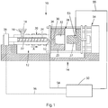
- FIG. 1 illustrates an exemplary low constant pressure injection molding apparatus 10 that generally includes an injection system 12 and a clamping system 14.
- thermoplastic material may be introduced to the injection system 12 in the form of thermoplastic pellets 16.
- the thermoplastic pellets 16 may be placed into a hopper 18, which feeds the thermoplastic pellets 16 into a heated barrel 20 of the injection system 12.
- the thermoplastic pellets 16, after being fed into the heated barrel 20, may be driven to the end of the heated barrel 20 by a reciprocating screw 22.
- the heating of the heated barrel 20 and the compression of the thermoplastic pellets 16 by the reciprocating screw 22 causes the thermoplastic pellets 16 to melt, forming a molten thermoplastic material 24.
- the molten thermoplastic material is typically processed at a temperature of about 130°C to about 410°C.
- the reciprocating screw 22 forces the molten thermoplastic material 24, toward a nozzle 26 to form a shot of thermoplastic material, which will be injected into a mold cavity 32 of a mold 28 via one or more gates 30, preferably three or less gates, that direct the flow of the molten thermoplastic material 24 to the mold cavity 32.
- the nozzle 26 may be separated from one or more gates 30 by a feed system (not shown).
- the mold cavity 32 is formed between first and second mold sides 25, 27 of the mold 28 and the first and second mold sides 25, 27 are held together under pressure by a press or clamping unit 34.
- the press or clamping unit 34 applies a clamping force during the molding process that is greater than the force exerted by the injection pressure acting to separate the two mold halves 25, 27, thereby holding the first and second mold sides 25, 27 together while the molten thermoplastic material 24 is injected into the mold cavity 32.
- the clamping system 14 may include a mold frame and a mold base.
- the mold 28 may include a plurality of mold cavities 32 to increase overall production rates.
- the shapes of the cavities of the plurality of mold cavities may be identical, similar or different from each other. (The latter may be considered a family of mold cavities).
- a controller 50 is communicatively connected with a nozzle sensor 52, located in the vicinity of the nozzle 26, a flow front sensor 53, located within the mold cavity 32 or proximate the mold cavity 32, and a screw control 36.
- the controller 50 may include a microprocessor, a memory, and one or more communication links.
- the flow front sensor 53 may provide an indication of of the location of a leading edge or flow front of the molten thermoplastic material flowing into the mold cavity 32. While the flow front sensor 53 is illustrated near an end of the mold cavity 32 (e.g., the location in the mold cavity that is last to fill with molten plastic material) in Fig.
- the flow front sensor 53 may be located at any point in the mold cavity 32 between a gate and the location in the mold cavity 32 that is last to fill with molten thermoplastic material. If the flow front sensor 53 is not located near the end of the mold cavity 32, a time correction factor may be applied to approximate when the flow front of the molten plastic material will reach the end of the mold cavity 32. It may be desirable to locate the flow front sensor 53 within 30% of the end of the mold cavity32, preferably within 20% of the end of the mold cavity 32, and more preferably within 10% of the end of the mold cavity 32.
- the nozzle sensor 52 and the flow front sensor 53 may sense the presence of thermoplastic material optically, pneumatically, electrically, ultrasonically, mechanically or otherwise by sensing pressure and/or temperature changes due to the arrival of the flow front of the thermoplastic material.
- the nozzle sensor 52 may send a signal indicative of the pressure or the temperature to the controller 50 to provide a target pressure for the controller 50 to maintain in the mold cavity 32 (or in the nozzle 26) as the fill is completed.
- This signal may generally be used to control the molding process, such that variations in material viscosity, mold temperatures, melt temperatures, and other variations influencing filling rate, are adjusted by the controller 50. These adjustments may be made immediately during the molding cycle, or corrections can be made in subsequent cycles.
- the controller 50 may be connected to the nozzle sensor 52, and/or the flow front sensor 53, and the screw control 36 via wired connections 54, 55, 56, respectively.
- the controller 50 may be connected to the nozzle sensors 52, to the flow front sensor 53, and to the screw control 56 via a wireless connection, a mechanical connection, a hydraulic connection, a pneumatic connection, or any other type of communication connection known to those having ordinary skill in the art that will allow the controller 50 to communicate with both the sensors 52, 53 and the screw control 36.
- the nozzle sensor 52 is a pressure sensor that measures (directly or indirectly) melt pressure of the molten thermoplastic material 24 in vicinity of the nozzle 26.
- the nozzle sensor 52 generates an electrical signal that is transmitted to the controller 50.
- the controller 50 then commands the screw control 36 to advance the screw 22 at a rate that maintains a desired melt pressure of the molten thermoplastic material 24 in the nozzle 26. This is known as a pressure controlled process.
- the nozzle sensor 52 may directly measure the melt pressure, the nozzle sensor 52 may also indirectly measure the melt pressure by measuring other characteristics of the molten thermoplastic material 24, such as temperature, viscosity, flow rate, etc, which are indicative of melt pressure.
- the nozzle sensor 52 need not be located directly in the nozzle 26, but rather the nozzle sensor 52 may be located at any location within the injection system 12 or mold 28 that is fluidly connected with the nozzle 26.
- the nozzle sensor 52 may not be located within the nozzle 26, appropriate correction factors may be applied to the measured characteristic to calculate an estimate of the melt pressure in the nozzle 26.
- the nozzle sensor 52 need not be in direct contact with the injected fluid and may alternatively be in dynamic communication with the fluid and able to sense the pressure of the fluid and/or other fluid characteristics. If the nozzle sensor 52 is not located within the nozzle 26, appropriate correction factors may be applied to the measured characteristic to calculate the melt pressure in the nozzle 26.
- the nozzle sensor 52 need not be disposed at a location that is fluidly connected with the nozzle. Rather, the nozzle sensor 52 could measure clamping force generated by the clamping system 14 at a mold parting line between the first and second mold parts 25, 27.
- the controller 50 may maintain the pressure according to the input from nozzle sensor 52. Alternatively, the sensor could measure an electrical power demand by an electric press, which may be used to calculate an estimate of the pressure in the nozzle 26.
- a pressure regulating valve (not shown) or a pressure relief valve (not shown) may replace the controller 50 to regulate the melt pressure of the molten thermoplastic material 24. More specifically, the pressure regulating valve and pressure relief valve can prevent overpressurization of the mold 28.
- Another alternative mechanism for preventing overpressurization of the mold 28 is an alarm that is activated when an overpressurization condition is detected.
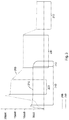
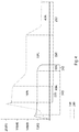
- the molded part 100 is a thin-walled part. Molded parts are generally considered to be thin-walled when a length of a flow channel L divided by a thickness of the flow channel T is greater than 100 (i.e., L/T > 100), but less than 1000.
- L/T may be calculated by integrating the T dimension over the length of the mold cavity 32 from the gate 30 to the end of the mold cavity 32, and determining the longest length of flow from the gate 30 to the end of the mold cavity 32. The L/T ratio can then be determined by dividing the longest length of flow by the average part thickness.
- the L/T ratio is determined by integrating L and T for the portion of the mold cavity 32 filled by each individual gate and the overall L/T ratio for a given mold cavity is the highest L/T ratio that is calculated for any of the gates.
- thin-walled parts may be defined as parts having an L/T > 100, or having an L/T > 200, but ⁇ 1000.
- the length of the flow channel L is the longest flow length as measured from the gate 30 to the end 104 of the mold cavity. Thin-walled parts are especially prevalent in the consumer products industry.
- High L/T ratio parts are commonly found in molded parts having average thicknesses less than about 10 mm. In consumer products, products having high L/T ratios generally have an average thickness of less than about 5 mm. For example, while automotive bumper panels having a high L/T ratio generally have an average thickness of 10 mm or less, tall drinking glasses having a high L/T ratio generally have an average thickness of about 5 mm or less, containers (such as tubs or vials) having a high L/T ratio generally have an average thickness of about 3mm or less, bottle cap enclosures having a high L/T ratio generally have an average thickness of about 2mm or less, and individual toothbrush bristles having a high L/T ratio generally have an average thickness of about 1 mm or less.
- the low constant pressure injection molding processes and devices disclosed herein are particularly advantageous for parts having a thickness of 5 mm or less and the disclosed processes and devices are more advantageous for thinner parts.
- Thin-walled parts with high L/T ratios present certain obstacles in injection molding.
- the thinness of the flow channel tends to cool the molten thermoplastic material before the material reaches the flow channel end 104. When this happens, the thermoplastic material freezes off and no longer flows, which results in an incomplete part.
- traditional injection molding machines inject the molten thermoplastic material at very high pressures, typically greater than 15,000 psi, so that the molten thermoplastic material rapidly fills the mold cavity before having a chance to cool and freeze off. This is one reason that manufacturers of the thermoplastic materials teach injecting at very high pressures. Another reason traditional injection molding machines inject at high pressures is the increased shear, which increases flow characteristics, as discussed above.
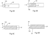
- the thin walled parts may include one or more special features 105, such as a living hinge, a filament, a closure, a dispenser, a spout, a bellows, and an actuator, that must be filled before the material freezes.
- thermoplastic material will flow when subjected to substantially constant pressure conditions, during an injection molding cycle, despite a portion of the mold cavity being below the no-flow temperature of the thermoplastic material.
- thermoplastic material would freeze and plug the mold cavity rather than continue to flow and fill the entire mold cavity.
- substantially constant pressure conditions, during an injection molding cycle, of embodiments of the disclosed method and device allow for dynamic flow conditions (i.e., constantly moving melt front) throughout the entire mold cavity during filling. There is no hesitation in the flow of the molten thermoplastic material as it flows to fill the mold cavity and, thus, no opportunity for freeze-off of the flow despite at least a portion of the mold cavity being below the no-flow temperature of the thermoplastic material.
- the molten thermoplastic material is able to maintain a temperature higher than the no-flow temperature, despite being subjected to such temperatures in the mold cavity, as a result of shear heating. It is further believed that the dynamic flow conditions interfere with the formation of crystal structures in the thermoplastic material as it begins the freezing process. Crystal structure formation increases the viscosity of the thermoplastic material, which can prevent suitable flow to fill the cavity. The reduction in crystal structure formation and/or crystal structure size can allow for a decrease in the thermoplastic material viscosity as it flows into the cavity and is subjected to the low temperature of the mold that is below the no-flow temperature of the material.
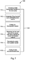
- the disclosed low constant pressure injection molding methods and systems may use a sensor (such as the flow front sensor 53 in Fig. 1 above) located within the mold cavity or proximate the mold cavity to monitor changes in material viscosity, changes in material temperature, and changes in other material properties. Measurements from this sensor may be communicated to the controller to allow the controller to correct the process in real time to ensure the melt front pressure is relieved prior to the melt front reaching the end of the mold cavity, which can cause flashing of the mold, and another pressure and power peak. Moreover, the controller may use the sensor measurements to adjust the peak power and peak flow rate points in the process, so as to achieve consistent processing conditions.
- a sensor such as the flow front sensor 53 in Fig. 1 above
- the controller may also to adjust the process over time (e.g., over a plurality of injection cycles). In this way, the current injection cycle can be corrected based on measurements occurring during one or more cycles at an earlier point in time. In one embodiment, sensor readings can be averaged over many cycles so as to achieve process consistency.
- the mold can include a cooling system that maintains the entire mold cavity at a temperature below the no-flow temperature. For example, even surfaces of the mold cavity which contact the shot comprising molten thermoplastic material can be cooled to maintain a lower temperature. Any suitable cooling temperature can be used.
- the mold can be maintained substantially at room temperature. Incorporation of such cooling systems can advantageously enhance the rate at which the as-formed injection molded part is cooled and ready for ejection from the mold.
- thermoplastic materials can be used in the low constant pressure injection molding methods and devices of the disclosure.
- the molten thermoplastic material has a viscosity, as defined by the melt flow index of about 0.1 g/10 min to about 500 g/10 min, as measured by ASTM D1238 performed at temperature of about 230C with a 2.16 kg weight.
- the melt flow index can be in a range of about 0.5 g/10 min to about 200 g/10 min.
- melt flow indexes include about 1 g/10 min to about 400 g/10 min, about 10 g/10 min to about 300 g/10 min, about 20 to about 200 g/10 min, about 30 g/10 min to about 100 g/10 min, about 50 g/10 min to about 75 g/10 min , about 0.1 g/10 min to about 1 g/10 min , or about 1 g/10 min to about 25 g/10 min.
- the MFI of the material is selected based on the application and use of the molded article. For examples, thermoplastic materials with an MFI of 0.1 g/10 min to about 5 g/10 min may be suitable for use as preforms for Injection Stretch Blow Molding (ISBM) applications. Thermoplastic materials with an MFI of 5 g/10 min to about 50 g/10 min may be suitable for use as caps and closures for packaging articles.
- Thermoplastic materials with an MFI of 50 g/10 min to about 150 g/10 min may be suitable for use in the manufacture of buckets or tubs.
- Thermoplastic materials with an MFI of 150 g/10min to about 500 g/10 min may be suitable for molded articles that have extremely high L/T ratios such as a thin plate.
- Manufacturers of such thermoplastic materials generally teach that the materials should be injection molded using melt pressures in excess of 6000 psi, and often in great excess of 6000 psi.
- embodiments of the low constant pressure injection molding method and device of the disclosure advantageously allow for forming quality injection molded parts using such thermoplastic materials and processing at melt pressures below 15,000 psi, and possibly well below 15,000 psi.
- the thermoplastic material can be, for example, a polyolefin.
- exemplary polyolefins include, but are not limited to, polypropylene, polyethylene, polymethylpentene, and polybutene-1. Any of the aforementioned polyolefins could be sourced from bio-based feedstocks, such as sugarcane or other agricultural products, to produce a bio-polypropylene or bio-polyethylene.
- Polyolefins advantageously demonstrate shear thinning when in a molten state. Shear thinning is a reduction in viscosity when the fluid is placed under compressive stress. Shear thinning can beneficially allow for the flow of the thermoplastic material to be maintained throughout the injection molding process.
- thermoplastic material results in less variation of the materials viscosity when the material is processed at constant pressures.
- embodiments of the method and device of the disclosure can be less sensitive to variations in the thermoplastic material, for example, resulting from colorants and other additives as well as processing conditions.
- This decreased sensitivity to batch-to-batch variations of the properties thermoplastic material can also advantageously allow post-industrial and post consumer recycled plastics to be processed using embodiments of the method and the device of the disclosure.
- Post-industrial, post consumer recycled plastics are derived from end products that have completed their life cycle as a consumer item and would otherwise have been disposed of as a solid waste product. Such recycled plastic, and blends of thermoplastic materials, inherently have significant batch-to-batch variation of their material properties..
- the thermoplastic material can also be, for example, a polyester.
- Exemplary polyesters include, but are not limited to, polyethylene terphthalate (PET).
- PET polymer could be sourced from bio-based feedstocks, such as sugarcane or other agricultural products, to produce a partially or fully bio-PET polymer.
- thermoplastic materials include copolymers of polypropylene and polyethylene, and polymers and copolymers of thermoplastic elastomers, polyester, polystyrene, polycarbonate, poly(acrylonitrile-butadiene-styrene), poly(lactic acid), bio-based polyesters such as poly(ethylene furanate) polyhydroxyalkanoate, poly(ethylene furanoate), (considered to be an alternative to, or drop-in replacement for, PET), polyhydroxyalkanoate, polyamides, polyacetals, ethylene-alpha olefin rubbers, and styrenebutadiene-styrene block copolymers.
- thermoplastic elastomers polyester, polystyrene, polycarbonate, poly(acrylonitrile-butadiene-styrene), poly(lactic acid), bio-based polyesters such as poly(ethylene furanate) polyhydroxyalkanoate, poly(ethylene furanoate), (considered to be an alternative to,
- the thermoplastic material can also be a blend of multiple polymeric and non-polymeric materials.
- the thermoplastic material can be, for example, a blend of high, medium, and low molecular polymers yielding a multi-modal or bi-modal blend.
- the multi-modal material can be designed in a way that results in a thermoplastic material that has superior flow properties yet has satisfactory chemo/physical properties.
- the thermoplastic material can also be a blend of a polymer with one or more small molecule additives.
- the small molecule could be, for example, a siloxane or other lubricating molecule that, when added to the thermoplastic material, improves the flowability of the polymeric material.
- additives may include inorganic fillers such calcium carbonate, calcium sulfate, talcs, clays (e.g., nanoclays), aluminum hydroxide, CaSiO3, glass formed into fibers or microspheres, crystalline silicas (e.g., quartz, novacite, crystallobite), magnesium hydroxide, mica, sodium sulfate, lithopone, magnesium carbonate, iron oxide; or, organic fillers such as rice husks, straw, hemp fiber, wood flour, or wood, bamboo or sugarcane fiber.
- inorganic fillers such calcium carbonate, calcium sulfate, talcs, clays (e.g., nanoclays), aluminum hydroxide, CaSiO3, glass formed into fibers or microspheres, crystalline silicas (e.g., quartz, novacite, crystallobite), magnesium hydroxide, mica, sodium sulfate, lithopone, magnesium carbonate, iron oxide; or, organic fillers such as rice husks, straw,
- thermoplastic materials include renewable polymers such as nonlimiting examples of polymers produced directly from organisms, such as polyhydroxyalkanoates (e.g., poly(beta-hydroxyalkanoate), poly(3-hydroxybutyrate-co-3-hydroxyvalerate, NODAX (Registered Trademark)), and bacterial cellulose; polymers extracted from plants, agricultural and forest, and biomass, such as polysaccharides and derivatives thereof (e.g., gums, cellulose, cellulose esters, chitin, chitosan, starch, chemically modified starch, particles of cellulose acetate), proteins (e.g., zein, whey, gluten, collagen), lipids, lignins, and natural rubber; thermoplastic starch produced from starch or chemically starch and current polymers derived from naturally sourced monomers and derivatives, such as bio-polyethylene, bio-polypropylene, polytrimethylene terephthalate, polylactic acid, NYLON 11, alkyd resins, succ
- the suitable thermoplastic materials may include a blend or blends of different thermoplastic materials such in the examples cited above.
- the different materials may be a combination of materials derived from virgin bio-derived or petroleum-derived materials, or recycled materials of bio-derived or petroleum-derived materials.
- One or more of the thermoplastic materials in a blend may be biodegradable.
- non-blend thermoplastic materials that material may be biodegradable.
- thermoplastic resins together with their recommended operating pressure ranges are provided in the following table: Material Full Name Injection Pressure Range (PSI) Company Material Brand Name pp Polypropylene 10000 - 15000 RTP Imagineering Plastics RTP 100 series Polypropylene Nylon 10000 - 18000 RTP Imagineering Plastics RTP 200 series Nylon ABS Acrylonitrile Butadiene Styrene 8000 - 20000 Marplex Astalac ABS PET Polyester 5800 - 14500 Asia International AIE PET 401F Acetal Copolymer 7000 - 17000 API Kolon Kocetal PC Pol ycarbonate 10000 - 15000 RTP Imagineering Plastics RTP 300 series Polycarbonate PS Polystyrene 10000 - 15000 RTP Imagineering Plastics RTP 400 series SAN Styrene Acrylonitrile 10000 - 15000 RTP Imagineering Plastics RTP 500 series PE LDPE & HDPE 10000 - 15000 RTP Imagineering Plastics RTP 700 Series TPE Thermoplastic E
- thermoplastic material While more than one of the embodiments involves filling substantially the entire mold cavity with the shot comprising the molten thermoplastic material while maintaining the melt pressure of the shot comprising the molten thermoplastic material at a substantially constant pressure during the injection molding cycle, specific thermoplastic materials benefit from the invention at different constant pressures.
- PP poly(ethylene furanate) polyhydroxyalkanoate, polyethylene furanoate (aka PEF) at substantially constant pressure of less than 10000 psi, or 8000 psi, or 7000 psi or 6000 psi, or 5800 psi.
- embodiments of the disclosed low constant pressure injection molding method and device can achieve one or more advantages over conventional injection molding processes.
- embodiments include a more cost effective and efficient process that eliminates the need to balance the pre-injection pressures of the mold cavity and the thermoplastic materials, a process that allows for use of atmospheric mold cavity pressures and, thus, simplified mold structures that eliminate the necessity of pressurizing means, the ability to use lower hardness, high thermal conductivity mold cavity materials that are more cost effective and easier to machine, a more robust processing method that is less sensitive to variations in the temperature, viscosity, and other material properties of the thermoplastic material, and the ability to produce quality injection molded parts at substantially constant pressures without premature hardening of the thermoplastic material in the mold cavity and without the need to heat or maintain constant temperatures in the mold cavity.
- a typical pressure-time curve for a conventional high variable pressure injection molding process is illustrated by the dashed line 200.
- a pressure-time curve for the disclosed low constant pressure injection molding machine is illustrated by the solid line 210.
- melt pressure is rapidly increased to well over 15,000 psi and then held at a relatively high pressure, more than 15,000 psi, for a first period of time 220.
- the first period of time 220 is the fill time in which molten plastic material flows into the mold cavity.
- the melt pressure is decreased and held at a lower pressure, typically 10,000 psi or more, for a second period of time 230.
- the second period of time 230 is a packing time in which the melt pressure is maintained to ensure that all gaps in the mold cavity are back filled.
- the pressure may optionally be dropped again for a third period of time 232, which is the cooling time.
- the mold cavity in a conventional high variable pressure injection molding system is packed from the end of the flow channel back to towards the gate. The material in the mold typically freezes off near the end of the cavity, then completely frozen off region of material progressively moves toward the gate location, or locations.
- the plastic near the end of the mold cavity is packed for a shorter time period and with reduced pressure, than the plastic material that is closer to the gate location, or locations.
- Part geometry such as very thin cross sectional areas midway between the gate and end of mold cavity, can also influence the level of packing pressure in regions of the mold cavity. Inconsistent packing pressure may cause inconsistencies in the finished product, as discussed above.
- the conventional packing of plastic in various stages of solidification results in some non-ideal material properties, for example, molded-in stresses, sink, and non-optimal optical properties.
- the low constant pressure injection molding system injects the molten plastic material into the mold cavity at a substantially constant pressure for a fill time period 240.
- the injection pressure in the example of FIG. 3 is less than 6,000 psi. However, other embodiments may use higher pressures.
- the low constant pressure injection molding system gradually reduces pressure over a second time period 242 as the molded part is cooled.
- the molten thermoplastic material maintains a continuous melt flow front that advances through the flow channel from the gate towards the end of the flow channel. In other words, the molten thermoplastic material remains moving throughout the mold cavity, which prevents premature freeze off.
- the plastic material remains relatively uniform at any point along the flow channel, which results in a more uniform and consistent finished product.
- the finished molded parts form crystalline structures that may have better mechanical and optical properties than conventionally molded parts.
- the parts molded at constant pressures exhibit different characteristics than skin layers of conventionally molded parts.
- parts molded under constant pressure may have better optical properties than parts of conventionally molded parts.
- the various stages of fill are broken down as percentages of overall fill time.
- the fill period 220 makes up about 10% of the total fill time
- the packing period 230 makes up about 50% of the total fill time
- the cooing period 232 makes up about 40% of the total fill time.
- the fill period 240 makes up about 90% of the total fill time while the cooling period 242 makes up only about 10% of the total fill time.
- the low constant pressure injection molding process needs less cooling time because the molten plastic material is cooling as it is flowing into the mold cavity.
- the molten plastic material has cooled significantly, although not quite enough to freeze off in the center cross section of the mold cavity, and there is less total heat to remove to complete the freezing process.
- the molten plastic material remains liquid throughout the fill, and packing pressure is transferred through this molten center cross section, the molten plastic material remains in contact with the mold cavity walls (as opposed to freezing off and shrinking away).
- the low constant pressure injection molding process described herein is capable of filling and cooling a molded part in less total time than in a conventional injection molding process.
- the part is molded by injecting a molten thermoplastic polymer into a mold cavity at an increasing flow rate to achieve a desired injection pressure and then decreasing the flow rate over time to maintain a substantially constant injection pressure.
- the low constant pressure injection molding method and device are particularly advantageous when molding thinwall parts (e.g., parts having an L/T ratio > 100 ⁇ 1000) and when using shot sizes of between 0.1g and 100g. It is especially advantageous that the maximum flow rate occur within the first 30% of cavity fill, preferably within the first 20% of cavity fill, and even more preferably within the first 10% of cavity fill.
- the molded part will have at least some of the physical advantages described above (e.g., better strength, better optical properties, etc.) because the crystalline structure of the molded part is different from a conventionally molded part. Moreover, because high L/T products are thinner, these products require less pigment to impart a desired color to the resulting product. Furthermore, in no-pigment parts, the parts will have less visible deformities due to the more consistent molding conditions. Using less or no pigment saves costs.
- the peak power may be adjusted to maintain a substantially constant injection pressure. More specifically, the filling pressure profile may be adjusted to cause the peak power to occur in the first 30% of the cavity fill, preferably in the first 20 % of the cavity fill, and even more preferably in the first 10% of the cavity fill. Adjusting the process to cause the peak power to occur within the preferred ranges, and then to have a decreasing power throughout the remainder of the cavity fill results in the same benefits for the molded part that were described above with respect to adjusting peak flow rate. Moreover, adjusting the process in the manner described above is particularly advantageous for thinwall parts (e.g., L/T ratio > 100 ⁇ 1000) and for shot sizes of between 0.1g and 100g).
- thinwall parts e.g., L/T ratio > 100 ⁇ 1000
- FIGS. 5A-5D and FIGS. 6A-6D a portion of a mold cavity as it is being filled by a conventional injection molding machine ( FIGS. 5A-5D ) and as it is being filled by a substantially constant pressure injection molding machine ( FIGS. 6A-6D ) is illustrated.
- This gap 35 reduces cooling efficiency of the mold.
- Molten thermoplastic material 24 also begins to cool and freeze in the vicinity of the gate 30, which reduces the effective cross-sectional area of the gate 30.
- the conventional injection molding machine In order to maintain a constant volumetric flow rate, the conventional injection molding machine must increase pressure to force molten thermoplastic material through the narrowing gate 30. As the thermoplastic material 24 continues to flow into the mold cavity 32, the boundary layer 33 grows thicker ( FIG. 5C ).
- thermoplastic material that is frozen ( FIG. 5D ).
- the conventional high pressure injection molding machine must maintain a packing pressure to push the receded boundary layer 33 back against the mold cavity 32 walls to increase cooling.
- a low constant pressure injection molding machine flows molten thermoplastic material into a mold cavity 32 with a constantly moving flow front 37 ( FIGS. 6A-6D ).
- the thermoplastic material 24 behind the flow front 37 remains molten until the mold cavity 37 is substantially filled (i.e., 99% or more filled) before freezing.
- the thermoplastic material 24 is molten behind the flow front 37, the thermoplastic material 24 remains in contact with the walls of the mold cavity 32.
- the thermoplastic material 24 is cooling (without freezing) during the fill portion of the molding process.
- the cooling portion of the disclosed low constant pressure injection molding process need not be as long as a conventional process.
- the injection pressure may be 15,000 psi or less.
- the injection systems and clamping systems need not be as powerful.
- the disclosed low constant pressure injection molding devices may use clamps requiring lower clamping forces, and a corresponding lower clamping power source.
- the disclosed low constant pressure injection molding machines because of the lower power requirements, may employ electric presses, which are generally not powerful enough to use in conventional class 101 and 102 injection molding machines that mold thinwall parts at high variable pressures.
- the disclosed low constant pressure injection molding machines may comprise one or more of the following types of electric presses, a direct servo drive motor press, a dual motor belt driven press, a dual motor planetary gear press, and a dual motor ball drive press having a power rating of 200 HP or less.
- FIG. 7 operation of an example molding cycle 1000 for the low constant pressure injection molding process is illustrated.
- the molding cycle 1000 may be carried out on a low constant pressure injection molding machine constructed in accordance with the disclosure, for example, on the low constant pressure injection molding machine of FIG. 1 .
- the example molding cycle 1000 may be carried out on a low constant pressure injection molding machine having a mold including a first mold side and a second mold side, at least one of the first mold side and the second mold side having an average thermal conductivity of more than 51.9 W/m-°C (30 BTU/HR FT °F) and less than or equal to 385.79 W/m-°C (223 BTU/HR FT °F), and a mold cavity that is formed between the first mold side and the second mold side.
- both the first and second mold side may have an average thermal conductivity of more than 51.9 W/m-°C (30 BTU/HR FT °F) and less than or equal to 385.79 W/m-°C (223 BTU/HR FT °F).
- Some preferred materials for manufacturing the first and/or second mold sides include aluminum (for example, 2024 aluminum, 2090 aluminum, 2124 aluminum, 2195 aluminum, 2219 aluminum, 2324 aluminum, 2618 aluminum, 5052 aluminum, 5059 aluminum, aircraft grade aluminum, 6000 series aluminum, 6013 aluminum, 6056 aluminum, 6061 aluminum, 6063 aluminum, 7000 series aluminum, 7050 aluminum, 7055 aluminum, 7068 aluminum, 7075 aluminum, 7076 aluminum, 7150 aluminum, 7475 aluminum, QC-10, AlumoldTM, HokotolTM, Duramold 2TM, Duramold 5TM, and Alumec 99TM), BeCu (for example, C17200, C 18000, C61900, C62500, C64700, C82500, Moldmax LHTM, Moldmax HHTM, and ProthermTM ) , Copper, and any alloys of aluminum (e.g., Beryllium, Bismuth, Chromium, Copper, Gallium, Iron, Lead, Magnesium, Manganese, Silicon, Titanium, Vanadium, Zin
- the disclosed low constant pressure injection molding methods and devices advantageously operate under molding conditions that allow molds made of these softer, higher thermal conductivity, materials to extract useful lives of more than 1 million cycles, preferably between 1.25 million cycles and 10 million cycles, and more preferably between 2 million cycles and 5 million cycles.
- molten thermoplastic material is advanced into a mold cavity that defines a thin-walled part (e.g., 100 ⁇ L/T ⁇ 1000) at 1110.
- a shot of molten thermoplastic material may be between 0.5g and 100g and may be advanced through three or fewer gates into the mold cavity.
- one or more of the three of fewer gates may have a cross-sectional area that is between 70% and 100% of a nominal wall thickness of a part that is formed in the mold cavity, and preferably between 80% and 90% of the nominal wall thickness. In some examples, this percentage may correspond to a gate size of between 0.5 mm and 10 mm..
- Molten thermoplastic material is advanced into the mold cavity until the mold cavity is substantially filled at 1112.
- the mold cavity may be substantially filled when the mold cavity is more than 90% filled, preferably more than 95% filled and more preferably more than 99% filled.
- the molten thermoplastic material is cooled at 1114 until the molten thermoplastic material is substantially frozen or solidified.
- the molten thermoplastic material may be actively cooled with a cooling liquid flowing through at least one of the first and second mold sides, or passively cooled through convection and conduction to the atmosphere.
- the first and second mold sides may be separated to expose the cooled thermoplastic material at 1116.
- the cooled thermoplastic material (in the form of the molded part) may be removed from the mold at 1118.
- the thermoplastic material may be removed by, for example, ejection, dumping, extraction (manually or via an automated process), pulling, pushing, gravity, or any other method of separating the cooled thermoplastic material from the first and second mold sides.
- Cycle time 1001 is defined as a single iteration of the molding cycle 1000.
- a single molding cycle may take between 2 seconds and 15 seconds, preferably between 8 seconds and 10 seconds, depending on the part size and material.
- pressure required to force the molten plastic into the mold will also change. For example, if viscosity increases, pressure required to force the polymer into the mold cavity will increase because the polymer is thicker and harder to move into the mold cavity. On the other hand, as viscosity decreases, pressure required force the polymer into the mold cavity will decrease because the polymer is thinner and easier to move into the mold cavity.
- the molded part will have flaws.
- Current injection molding machines and processes have molding cycles that are time-based. In other words, the molding cycle is controlled by time, among other factors, as the injection molding cycle is ended at a predetermined time. As a result, changes in viscosity to the molten plastic material will cause the molten plastic material to reach in end of the mold cavity at a time that is different from the predetermined time.
- FIG. 8 a pressure versus time graph is illustrated for a single injection molding cycle.
- a predetermined target value 1210 e.g., a "fill pressure”
- the pressure is held as the mold cavity is filled.
- a first time t t (or t transducer ) 1212 pressure is reduced slightly at 1214 to a lower pressure (e.g., a "pack and hold pressure") as the material in the mold cavity 32 cools.
- t s or t step
- Changes in viscosity of the molten plastic material may affect the time at which the molten plastic material reaches the end of the mold cavity 32 or the end of fill location in the mold cavity at t s . For example, if viscosity of the molten plastic material increases, (with the possibility of a "short shot"), then the molten plastic material may be maintained at the fill pressure for a longer time, as illustrated by dashed line 1220a.
- the flow front sensor 53 may detect the molten plastic material at a time that is later than a predetermined time. A predetermined time for the molten plastic to reach the flow front sensor may be calculated or derived experimentally for ideal conditions and constant viscosity for the molten plastic material.
- the molten plastic material may be maintained at the fill pressure for a shorter time, as illustrated by the dashed line 1220b.
- the flow front sensor 53 may detect molten plastic material at a time t t that is earlier than the predetermined time.
- the controller 50 may cause the screw control 26 ( FIG. 1 ) to increase or decrease the step time (t s ) based on the change in viscosity to ensure that the mold cavity 32 is completely filled with molten plastic without being overfilled.
- FIG. 9 a corrected pressure versus time graph is illustrated. For example, if viscosity of the molten plastic material increases, the controller 50 instructs the screw control 26 to increase step time, as illustrated by line 1222a, resulting in a new step time (t s1 ) that is longer than the predetermined step time.
- the controller 50 instructs the screw control 26 to decrease step time, as illustrated by line 1222b, resulting in a new step time (t s2 ) that is shorter than the predetermined step time.
- FIG. 10 the logic diagram of the process 1400 for accounting for changes in flowability of the molten plastic material is illustrated.
- a first shot of molten plastic material is injected into the mold cavity 32 at a predetermined target injection (or fill) pressure, and pressure on the first shot of molten plastic material is removed so that the first mold cycle has a first step time at 1410.
- the flow front sensor 53 sends a signal to the controller 50 indicative of when the flow front of the molten plastic material passes the flow front sensor 53 at 1420.
- the controller 50 compares the first time to a predetermined time.
- the controller 50 calculates a step time correction that is required to compensate for the difference between the first time and the predetermined time at 1440.
- the controller 50 instructs the screw controller 26 to remove injection pressure from a second shot of molten plastic material so that the second mold cycle has a second step time that is different from the first step time at 1450, and the second step time is based on the difference between the first time and the predetermined time.
- the controller 50 may continue to compare such times and to make subsequent step time adjustments based on the difference between the two.
- the second subsequent molding cycle may be immediately subsequent to the first molding cycle.
- first molding cycle and the second molding cycle may be separated by one or more intervening molding cycles.
- the controller may average (or otherwise combine) the times over two or more molding cycles and calculate a step time correction that may be applied to a third subsequent molding cycle.
- controller 50 may employ other control methodology including, but not limited to, statistical control methodology utilizing moving or non-moving averages, control charting, and the elimination of statistically outlying data points.
- the second step time may be proportional to the difference between the first time and the predetermined time. When viscosity of the molten plastic material increases, the second step time will be greater. On the other hand, when viscosity of the molten plastic material decreases, the second step time will be less. The second step time will generally be between 350% greater than and 75% less than the first step time.
- the controller 50 may average the second time with the first time and then compare the average to the predetermined time. By using an average, the controller 50 may smooth changes to the step times, thereby enhancing uniformity of part quality, while still accounting for changes in viscosity.
- FIG. 11 an alternate embodiment of a logic diagram for a process 1500 for accounting for changes in flowability of the molten plastic material is illustrated.
- the main difference from the previous embodiment of FIG. 10 is that the process of FIG. 11 adjusts the step time intracycle. In other words, the process of FIG. 11 calculates an adjusted step time within a single cycle.
- the embodiments of FIG. 10 and FIG. 11 may be combined to result in a process that calculates a revised step time during a first cycle and then continues calculating a revised step time for each subsequent cycle.
- the combination of the two disclosed processes may result in a process that calculates an adjusted step time both intracycle and intercycle.
- any of the modifications to the process described with reference to FIG. 10 may also modify the process described below with reference to FIG. 11 .
- a predetermined time may be obtained at 1510.
- the predetermined time may be for a shot of molten plastic material having a known flowability.
- the predetermined time may be calculated by a processor, or input by a user into an injection molding system.
- a first shot of molten plastic material may be injected into a mold cavity at 1520.
- a first time for the molten plastic material to reach the flow front sensor may be measured at 1530.
- the first time may be compared with the predetermined time to produce a first comparison result at 1540.
- a first step time may be determined at 1550. The first step time by be based, at least in part, on the first comparison result.
- injection pressure may be removed from the first shot of molten plastic material at the first step time at 1560, during the first injection molding cycle.
- the material with an 11 MFI took approximately 2.499 seconds to completely fill the mold cavity while the material with a 30 MFI took only 0.719 seconds to completely fill the mold cavity.
- the times to fill the mold cavity in this example varied within the range of +350% to - 75%.
- the injection molding methods described herein account for these differences in fill time and adjust the cycle step times accordingly to reliably produce better quality parts.
- changes in the viscosity of the molten plastic material may be caused by any number of factors.
- an operator may desire to reuse poor quality parts by re-grinding the poor quality parts and mixing the reground plastic material with virgin plastic material.
- an operator may desire to change part color during an injection run by introducing a colorant into the molten plastic material.
- the introduction of a colorant will often change the MFI of the molten plastic material.
- changes in ambient operating conditions can also change the viscosity of the molten plastic material. For example, if ambient temperature increases, viscosity of the molten plastic material often increases. Likewise, if ambient temperature decreases, viscosity the molten plastic material often decreases.
- the disclosed low constant pressure injection molding methods and machines advantageously reduce cycle time for the molding process while increasing part quality.
- the disclosed low constant pressure injection molding machines may employ, in some embodiments, electric presses, which are generally more energy efficient and require less maintenance than hydraulic presses.
- the disclosed low constant pressure injection molding machines are capable of employing more flexible support structures and more adaptable delivery structures, such as wider platen widths, increased tie bar spacing, elimination of tie bars, lighter weight construction to facilitate faster movements, and non-naturally balanced feed systems.
- the disclosed low constant pressure injection molding machines may be modified to fit delivery needs and are more easily customizable for particular molded parts.
- the disclosed low constant pressure injection molding machines and methods allow the molds to be made from softer materials (e.g., materials having a Rc of less than about 30), which may have higher thermal conductivities (e.g., thermal conductivities greater than about 20 BTU/HR FT °F), which leads to molds with improved cooling capabilities and more uniform cooling.
- the disclosed low constant pressure injection molds may include simplified cooling systems.
- the simplified cooling systems include fewer cooling channels and the cooling channels that are included may be straighter, having fewer machining axes.
- U.S. Patent Application No. 61/602,781 filed February 24, 2012 .
- the lower injection pressures of the low constant pressure injection molding machines allow molds made of these softer materials to extract 1 million or more molding cycles, which would not be possible in conventional injection molding machines as these materials would fail before 1 million molding cycles in a high pressure injection molding machine.
- the terms “substantially,” “about,” and “approximately,” unless otherwise specified, may be utilized herein to represent the inherent degree of uncertainty that may be attributed to any quantitative comparison, value, measurement, or other representation. These terms are also utilized herein to represent the degree by which a quantitative representation may vary from a stated reference without resulting in a change in the basic function of the subject matter at issue. Unless otherwise defined herein, the terms “substantially,” “about,” and “approximately” mean the quantitative comparison, value, measurement, or other representation may fall within 20% of the stated reference.
- Part, parts, or all of any of the embodiments disclosed herein can be combined with part, parts, or all of other injection molding embodiments known in the art, including those described below.
- Embodiments of the present disclosure can be used with embodiments for injection molding at low constant pressure, as disclosed in US patent application 13/476,045 filed May 21, 2012 , entitled “Apparatus and Method for Injection Molding at Low Constant Pressure” and published as US 2012-0294963 A1 .
- Embodiments of the present disclosure can be used with embodiments for pressure control, as disclosed in US patent application 13/476,047 filed May 21, 2012 , entitled “Alternative Pressure Control for a Low Constant Pressure Injection Molding Apparatus” now US patent 8,757,999 .
- Embodiments of the present disclosure can be used with embodiments for non-naturally balanced feed systems, as disclosed in US patent application 13/476,073 filed May 21, 2012 , entitled “Non-Naturally Balanced Feed System for an Injection Molding Apparatus” and published as US 2012-0292823 A1 .
- Embodiments of the present disclosure can be used with embodiments for injection molding at low, substantially constant pressure, as disclosed in US patent application 13/476,197 filed May 21, 2012 , entitled “Method for Injection Molding at Low, Substantially Constant Pressure” and published as US 2012-0295050 A1 .
- Embodiments of the present disclosure can be used with embodiments for injection molding at low, substantially constant pressure, as disclosed in US patent application 13/476,178 filed May 21, 2012 , entitled “Method for Injection Molding at Low, Substantially Constant Pressure” and published as US 2012-0295049 A1 .
- Embodiments of the present disclosure can be used with embodiments for co-injection processes, as disclosed in US patent application 13/774,692 filed February 22, 2013 , entitled "High Thermal Conductivity Co-Injection Molding System”.
- Embodiments of the present disclosure can be used with embodiments for molding with simplified cooling systems, as disclosed in US patent application 13/765,428 filed February 12, 2013 , entitled "Injection Mold Having a Simplified Evaporative Cooling System or a Simplified Cooling System with Exotic Cooling Fluids", now US patent 8,591,219 .
- Embodiments of the present disclosure can be used with embodiments for molding thinwall parts, as disclosed in US patent application 13/476,584 filed May 21, 2012 , entitled “Method and Apparatus for Substantially Constant Pressure Injection Molding of Thinwall Parts".
- Embodiments of the present disclosure can be used with embodiments for molding with a failsafe mechanism, as disclosed in US patent application 13/672,246 filed November 8, 2012 , entitled "Injection Mold With Fail Safe Pressure Mechanism”.
- Embodiments of the present disclosure can be used with embodiments for high-productivity molding, as disclosed in US patent application 13/682,456 filed November 20, 2012 , entitled “Method for Operating a High Productivity Injection Molding Machine”.
- Embodiments of the present disclosure can be used with embodiments for molding certain thermoplastics, as disclosed in US patent application 14/085,515 filed November 20, 2013 , entitled “Methods of Molding Compositions of Thermoplastic Polymer and Hydrogenated Castor Oil”.
- Embodiments of the present disclosure can be used with embodiments for runner systems, as disclosed in US patent application 14/085,515 filed November 21, 2013 , entitled "Reduced Size Runner for an Injection Mold System”.
- Embodiments of the present disclosure can be used with embodiments for moving molding systems, as disclosed in US patent application 61/822,661 filed May 13, 2013 , entitled “Low Constant Pressure Injection Molding System with Variable Position Molding Cavities:"
- Embodiments of the present disclosure can be used with embodiments for injection mold control systems, as disclosed in US patent application 61/861,298 filed August 20, 2013 , entitled “Injection Molding Machines and Methods for Accounting for Changes in Material Properties During Injection Molding Runs”.
- Embodiments of the present disclosure can be used with embodiments for injection mold control systems, as disclosed in US patent application 61/861,304 filed August 20, 2013 , entitled “Injection Molding Machines and Methods for Accounting for Changes in Material Properties During Injection Molding Runs”.
- Embodiments of the present disclosure can be used with embodiments for injection mold control systems, as disclosed in US patent application 61/861,310 filed August 20, 2013 , entitled “Injection Molding Machines and Methods for Accounting for Changes in Material Properties During Injection Molding Runs”.
- Embodiments of the present disclosure can be used with embodiments for using injection molding to form overmolded articles, as disclosed in US patent application 61/918,438 filed December 19, 2013 , entitled “Methods of Forming Overmolded Articles”.
- Embodiments of the present disclosure can be used with embodiments for controlling molding processes, as disclosed in US patent 5,728,329 issued March 17, 1998 , entitled “Method and Apparatus for Injecting a Molten Material into a Mold Cavity”.
- Embodiments of the present disclosure can be used with embodiments for controlling molding processes, as disclosed in US patent 5,716,561 issued February 10, 1998 , entitled “Injection Control System”.
- Embodiments of the present disclosure can be used with embodiments for molding preforms, as disclosed in US patent application 61/952281 , entitled “Plastic Article Forming Apparatus and Methods for Using the Same”.
- Embodiments of the present disclosure can be used with embodiments for molding preforms, as disclosed in US patent application 61/952283 , entitled “Plastic Article Forming Apparatus and Methods for Using the Same”.
Landscapes
- Engineering & Computer Science (AREA)
- Manufacturing & Machinery (AREA)
- Mechanical Engineering (AREA)
- Injection Moulding Of Plastics Or The Like (AREA)
- Moulds For Moulding Plastics Or The Like (AREA)
Claims (14)
- Procédé (1400) pour ajuster automatiquement une durée d'étape pour un cycle de moulage par injection dans une opération de moulage par injection pour s'adapter à des variations de la fluidité d'une matière plastique fondue, le procédé comprenant :(a) pendant un premier cycle de moulage d'une opération de moulage par injection, injecter (1410) une première charge d'injection de matière plastique fondue dans une cavité de moule, et supprimer une pression d'injection de la première charge d'injection de matière plastique fondue de telle sorte que le premier cycle de moulage a une première durée d'étape ; etcaractérisé par le fait que le procédé comprend en outre :(b) pendant le premier cycle de moulage, mesurer (1420) une première durée que la matière plastique fondue met pour atteindre un capteur de front d'écoulement (53) qui est configuré pour détecter la présence d'un front d'écoulement de la matière plastique fondue à un emplacement particulier dans la cavité de moule ;(c) une première comparaison (1430) de la première durée à une durée prédéterminée pour déterminer un premier résultat de comparaison ;(d) déterminer (1440) une deuxième durée d'étape sur la base, au moins en partie, du premier résultat de comparaison ; et(e) pendant un deuxième cycle de moulage de l'opération de moulage par injection, après le premier cycle de moulage, injecter (1450) une deuxième charge d'injection de matière plastique fondue dans la cavité de moule, et supprimer une pression d'injection de la deuxième charge d'injection de matière plastique fondue de telle sorte que le deuxième cycle de moulage a la deuxième durée d'étape.
- Procédé selon la revendication 1, comprenant déterminer la durée prédéterminée sur la base, au moins en partie, d'une durée qu'une charge d'injection de matière plastique fondue, ayant une fluidité connue, met pour atteindre le capteur de front d'écoulement.
- Procédé selon l'une quelconque des revendications précédentes, dans lequel la mesure comprend mesurer la première durée à partir du début du premier cycle de moulage jusqu'à ce que le capteur de front d'écoulement détecte l'arrivée du front d'écoulement de la matière plastique fondue.
- Procédé selon l'une quelconque des revendications précédentes, dans lequel la comparaison consiste à déterminer si la première durée est supérieure ou inférieure à la durée prédéterminée.
- Procédé selon la revendication 4, dans lequel la première comparaison comprend comparer la première durée à la durée prédéterminée pour déterminer un premier résultat de comparaison, qui est une différence de temps entre la première durée et la durée prédéterminée.
- Procédé selon l'une quelconque des revendications 1 à 5, dans lequel :la première comparaison comprend déterminer que la première durée est supérieure à la durée prédéterminée ; etla suppression comprend supprimer une pression d'injection de la deuxième charge d'injection de matière plastique fondue de telle sorte que le deuxième cycle de moulage a une deuxième durée d'étape qui est supérieure à la première durée d'étape.
- Procédé selon l'une quelconque des revendications 1 à 5, dans lequel :la première comparaison comprend déterminer que la première durée est inférieure à la durée prédéterminée ; etla suppression comprend supprimer une pression d'injection de la deuxième charge d'injection de matière plastique fondue de telle sorte que le deuxième cycle de moulage a une deuxième durée d'étape qui est inférieure à la première durée d'étape.
- Procédé selon l'une quelconque des revendications précédentes, dans lequel, pendant le premier cycle de moulage, la mesure comprend mesurer la première durée que la matière plastique fondue met pour atteindre le capteur de front d'écoulement, qui est un transducteur.
- Procédé selon l'une quelconque des revendications précédentes, dans lequel, pendant le premier cycle de moulage, la mesure comprend mesurer la première durée que la matière plastique fondue met pour atteindre le capteur de front d'écoulement, qui se situe dans les limites de 30 % d'une extrémité de la cavité de moule.
- Procédé selon l'une quelconque des revendications précédentes, dans lequel, pendant le premier cycle de moulage, la mesure comprend mesurer la première durée que la matière plastique fondue met pour atteindre le capteur de front d'écoulement, qui est un capteur configuré pour détecter directement la présence d'un front d'écoulement de la matière plastique fondue à l'intérieur de la cavité de moule.
- Procédé selon l'une quelconque des revendications précédentes, comprenant en outre :(f) pendant le deuxième cycle de moulage, mesurer une deuxième durée que la matière plastique fondue met pour atteindre le capteur de front d'écoulement ; et(g) une seconde comparaison de la deuxième durée à la durée prédéterminée, pour déterminer un deuxième résultat de comparaison ;(h) déterminer une troisième durée d'étape, sur la base, au moins en partie, du deuxième résultat de comparaison ; et(i) pendant un troisième cycle de moulage de l'opération de moulage par injection, après le deuxième cycle de moulage, injecter une troisième charge d'injection de matière plastique fondue dans la cavité de moule, et supprimer une pression d'injection de la troisième charge d'injection de matière plastique fondue de telle sorte que le troisième cycle de moulage a la troisième durée d'étape.
- Procédé selon l'une quelconque des revendications précédentes, comprenant, pour chaque cycle de moulage dans l'opération de moulage par injection, ajuster automatiquement sa durée d'étape sur la base d'une comparaison qui utilise la durée prédéterminée.
- Procédé selon l'une quelconque des revendications précédentes, comprenant, pour chaque cycle de moulage dans l'opération de moulage par injection, ajuster automatiquement sa durée d'étape, sur la base d'un résultat de comparaison qui utilise une durée, dans un cycle de moulage antérieur, qu'une charge d'injection de matière plastique fondue met pour atteindre le capteur de front d'écoulement.
- Machine de moulage (10) qui comprend un dispositif de commande (50) configuré pour ajuster automatiquement une durée d'étape pour un cycle de moulage par injection dans une opération de moulage par injection pour s'adapter à des variations de la fluidité d'une matière plastique fondue, afin de réaliser le procédé selon l'une quelconque des revendications précédentes.
Applications Claiming Priority (2)
| Application Number | Priority Date | Filing Date | Title |
|---|---|---|---|
| US201361861304P | 2013-08-01 | 2013-08-01 | |
| PCT/US2014/049150 WO2015017658A1 (fr) | 2013-08-01 | 2014-07-31 | Machines à mouler par injection et procédés tenant compte des variations des propriétés du matériau lors des opérations de moulage par injection |
Publications (2)
| Publication Number | Publication Date |
|---|---|
| EP3027380A1 EP3027380A1 (fr) | 2016-06-08 |
| EP3027380B1 true EP3027380B1 (fr) | 2019-06-19 |
Family
ID=51352866
Family Applications (2)
| Application Number | Title | Priority Date | Filing Date |
|---|---|---|---|
| EP14750948.3A Active EP3027380B1 (fr) | 2013-08-01 | 2014-07-31 | Machines à mouler par injection et procédés tenant compte des variations des propriétés du matériau lors des opérations de moulage par injection |
| EP14750950.9A Active EP3027381B1 (fr) | 2013-08-01 | 2014-07-31 | Machines de moulage par injection et procédés permettant de tenir compte de changements dans des propriétés physiques des matières pendant des campagnes de moulage par injection |
Family Applications After (1)
| Application Number | Title | Priority Date | Filing Date |
|---|---|---|---|
| EP14750950.9A Active EP3027381B1 (fr) | 2013-08-01 | 2014-07-31 | Machines de moulage par injection et procédés permettant de tenir compte de changements dans des propriétés physiques des matières pendant des campagnes de moulage par injection |
Country Status (12)
| Country | Link |
|---|---|
| US (2) | US9475226B2 (fr) |
| EP (2) | EP3027380B1 (fr) |
| JP (2) | JP6181872B2 (fr) |
| KR (2) | KR20160027140A (fr) |
| CN (2) | CN105431273B (fr) |
| AU (2) | AU2014296147A1 (fr) |
| BR (2) | BR112016002259A2 (fr) |
| CA (2) | CA2919378C (fr) |
| MX (2) | MX354732B (fr) |
| PH (2) | PH12016500202A1 (fr) |
| RU (2) | RU2016102963A (fr) |
| WO (2) | WO2015017658A1 (fr) |
Cited By (1)
| Publication number | Priority date | Publication date | Assignee | Title |
|---|---|---|---|---|
| DE102020117665A1 (de) | 2020-07-03 | 2022-01-05 | Rheinisch-Westfälische Technische Hochschule (Rwth) Aachen | Phasenvereinende, modellbasierte, prädiktive Regelung einer Spritzgießmaschine sowie Spritzgießmaschine mit einer derartigen Regelung |
Families Citing this family (12)
| Publication number | Priority date | Publication date | Assignee | Title |
|---|---|---|---|---|
| US8980146B2 (en) | 2013-08-01 | 2015-03-17 | Imflux, Inc. | Injection molding machines and methods for accounting for changes in material properties during injection molding runs |
| WO2015017658A1 (fr) | 2013-08-01 | 2015-02-05 | iMFLUX Inc. | Machines à mouler par injection et procédés tenant compte des variations des propriétés du matériau lors des opérations de moulage par injection |
| US20160158986A1 (en) * | 2013-08-09 | 2016-06-09 | Nissan Motor Co. Ltd. | Injection control method and injection control system |
| WO2016125160A1 (fr) * | 2015-02-05 | 2016-08-11 | Mitraltech Ltd. | Valve prothétique avec cadres coulissant axialement |
| WO2018187254A1 (fr) * | 2017-04-04 | 2018-10-11 | iMFLUX Inc. | Détermination non-dépendante du temps dans le moule de la préparation à l'injection d'une pièce moulée |
| MX2019014014A (es) | 2017-06-21 | 2020-08-17 | Imflux Inc | Moldeo por inyeccion de polimeros de reticulacion usando datos de tension. |
| EP3787869B1 (fr) * | 2018-05-02 | 2023-08-16 | Imflux Inc. | Systèmes et procédés de commande de moulage par injection à l'aide d'une pression de cavité prédite |
| CN110044517B (zh) * | 2019-03-06 | 2020-09-29 | 泉州圆创机械技术开发有限公司 | 一种3d打印机用移动式温度传感器 |
| US11673307B2 (en) | 2019-06-25 | 2023-06-13 | iMFLUX Inc. | Methods for controlling co-injection plastic pressure ratio between individual flow front layers |
| JP7333245B2 (ja) * | 2019-10-28 | 2023-08-24 | 芝浦機械株式会社 | 溶融樹脂の流動性指標制御方法および装置 |
| WO2021144392A1 (fr) * | 2020-01-14 | 2021-07-22 | Berry Superfos Randers A/S | Procédé de fabrication d'un récipient |
| CN111361108B (zh) * | 2020-04-08 | 2021-12-17 | 台州市黄岩博涛塑业有限公司 | 一种利用熔化原料的高温增加注射压力的眼镜架加工装置 |
Family Cites Families (53)
| Publication number | Priority date | Publication date | Assignee | Title |
|---|---|---|---|---|
| US3642404A (en) | 1968-11-21 | 1972-02-15 | Meiki Seisakusho Kk | Injection-molding machine |
| US3628901A (en) | 1969-07-15 | 1971-12-21 | New Britain Machine Co | Means for monitoring product quality in a plastics injection-molding machine |
| US3695800A (en) | 1970-03-10 | 1972-10-03 | Pennwalt Corp | Time monitored injection molding control apparatus |
| US3893792A (en) | 1973-04-06 | 1975-07-08 | Bbf Group Inc | Controller for injection molding machine |
| US4066725A (en) | 1973-12-03 | 1978-01-03 | Barber-Colman Company | Injection molding control method |
| US3859400A (en) * | 1974-01-11 | 1975-01-07 | Cincinnati Milacron Inc | Method for injection molding machine automatic control |
| JPS59224323A (ja) | 1983-06-03 | 1984-12-17 | Tekunopurasu:Kk | 型内圧波形による監視方法 |
| JPH0659675B2 (ja) | 1987-01-30 | 1994-08-10 | 住友重機械工業株式会社 | 射出圧力設定方法及び射出成形機 |
| US4816197A (en) * | 1988-04-12 | 1989-03-28 | Hpm Corporation | Adaptive process control for injection molding |
| JPH03138123A (ja) * | 1989-10-24 | 1991-06-12 | Sekisui Chem Co Ltd | 射出成形における充填時間の設定方法 |
| US5578256A (en) | 1990-03-28 | 1996-11-26 | Moldflow Pty, Ltd | Control of injection moulding machine |
| JPH0753405B2 (ja) | 1991-11-28 | 1995-06-07 | 花王株式会社 | 射出成形機における樹脂流動物性変動制御方法および装置 |
| US5716561A (en) | 1994-05-02 | 1998-02-10 | Guergov; Milko G. | Injection control system |
| US5441680B1 (en) | 1994-05-02 | 1997-04-29 | Milko G Guergov | Method and apparatus for injection molding |
| CH688441A5 (de) | 1994-10-19 | 1997-09-30 | Kk Holding Ag | Verfahren zur Bestimmung des Umschaltpunktes bei der Herstellung eines Spritzgussteils. |
| EP0749821B1 (fr) * | 1995-06-19 | 2003-03-05 | Siebolt Hettinga | Procédé sous basse pression pour mouler par injection un article en matière plastique |
| DE19536566C1 (de) * | 1995-10-02 | 1997-02-06 | Arburg Gmbh & Co | Verfahren zur Regelung des Werkzeuginnendrucks an einer zyklisch arbeitenden Maschine |
| JP3810984B2 (ja) | 2000-05-08 | 2006-08-16 | 東芝機械株式会社 | ダイカストマシンの射出制御方法 |
| JP3794252B2 (ja) | 2000-07-26 | 2006-07-05 | 東芝機械株式会社 | 電動式射出成形機および電動式射出成形機の射出制御方法 |
| DE10112125A1 (de) | 2001-03-14 | 2002-10-10 | Frey Juergen | Verfahren zum Regeln von Prozessparametern zur Erzielung konstanter Prozessbedingungen |
| DE10112126B4 (de) | 2001-03-14 | 2004-03-25 | Priamus System Technologies Ag | Verfahren zum automatischen Balancieren der volumetrischen Füllung von Kavitäten |
| DE10114228A1 (de) | 2001-03-22 | 2002-10-02 | Frey Juergen | Verfahren zum Regeln der Schwindung von Spritzteilen |
| DE10117000A1 (de) | 2001-04-05 | 2002-11-21 | Frey Juergen | Verfahren zum automatischen Erkennen der Empfindlichkeit von Sensoren |
| US7682535B2 (en) | 2001-04-05 | 2010-03-23 | Priamus System Technologies Ag | Method of filling the cavity of a tool |
| DE10117001A1 (de) | 2001-04-05 | 2002-11-07 | Frey Juergen | Verfahren zum Herstellen eines Formteiles in einem Formwerkzeug |
| JP3696826B2 (ja) * | 2001-11-22 | 2005-09-21 | 株式会社日本製鋼所 | 超臨界流体の注入装置及びそれを備えた射出成形機 |
| TWI235706B (en) | 2003-04-07 | 2005-07-11 | Sumitomo Heavy Industries | Method of controlling injection molding machine |
| DE10359975A1 (de) | 2003-12-18 | 2005-07-14 | Priamus System Technologies Ag | Verfahren zum Betreiben einer Arbeitsgerätschaft |
| DE102004003278A1 (de) | 2004-01-21 | 2005-08-25 | Priamus System Technologies Ag | Sensor |
| DE102004031546A1 (de) | 2004-06-29 | 2006-02-09 | Priamus System Technologies Ag | Verfahren zum Füllen von zumindest einer Kavität |
| DE102004043443B3 (de) | 2004-09-06 | 2006-02-02 | Priamus System Technologies Ag | Vorrichtung zum Formen von Gegenständen |
| DE102004051109B4 (de) | 2004-10-19 | 2007-01-18 | Siemens Ag | Verfahren zum Betrieb einer Spritzgießmaschine |
| DE102005029705A1 (de) | 2005-06-10 | 2006-12-14 | Priamus System Technologies Ag | Verfahren zum Regeln des Spritzgiesprozesses einer Spritzgiessmaschine |
| DE102005032367A1 (de) * | 2005-07-08 | 2007-01-11 | Priamus System Technologies Ag | Verfahren zum Überwachen und/oder Regeln der Schmelzebefüllung von zumindest einer Kavität |
| WO2009040077A1 (fr) * | 2007-09-20 | 2009-04-02 | Priamus System Technologies Ag | Procédé et dispositif pour surveiller, documenter et/ou réguler une presse d'injection |
| DE102007061775A1 (de) | 2007-12-20 | 2009-07-02 | Geiger Technik Gmbh | Spritzgussverfahren und zugehörige Anlage |
| US9387617B2 (en) * | 2009-10-12 | 2016-07-12 | Kistler Holding Ag | Method for controlling an injection process in an open-loop or closed-loop manner |
| US9821499B2 (en) | 2011-01-17 | 2017-11-21 | Priamus System Technologies Ag | Process for producing multilayered articles |
| KR20140006065A (ko) | 2011-05-20 | 2014-01-15 | 더 프록터 앤드 갬블 캄파니 | 낮은, 실질적으로 일정한 압력에서의 사출 성형을 위한 방법 |
| JP5848443B2 (ja) | 2011-05-20 | 2016-01-27 | アイエムフラックス インコーポレイテッド | 薄肉部品の実質的に一定圧力の射出成形のための方法 |
| RU2565176C2 (ru) | 2011-05-20 | 2015-10-20 | иМФЛАКС Инк. | Система подачи без естественного баланса для устройства инжекционного формования |
| US8757999B2 (en) | 2011-05-20 | 2014-06-24 | The Procter & Gamble Company | Alternative pressure control for a low constant pressure injection molding apparatus |
| AU2012259036B2 (en) | 2011-05-20 | 2016-04-14 | iMFLUX Inc. | Apparatus and method for injection molding at low constant pressure |
| RU2567906C2 (ru) | 2011-05-20 | 2015-11-10 | иМФЛАКС Инк., | Способ инжекционного формования при низком, в сущности, постоянном давлении |
| US9446544B2 (en) * | 2011-07-01 | 2016-09-20 | University Of Connecticut | Method and system for multivariate remote monitoring of polymer processing |
| US20130221575A1 (en) | 2012-02-24 | 2013-08-29 | The Procter & Gamble Company | Method for Operating a High Productivity Injection Molding Machine |
| US20130295219A1 (en) | 2012-05-02 | 2013-11-07 | Ralph Edwin Neufarth | Injection Mold Having a Simplified Evaporative Cooling System or a Simplified Cooling System with Exotic Cooling Fluids |
| BR112016002260A2 (pt) | 2013-08-01 | 2017-08-29 | Imflux Inc | Máquinas de moldagem por injeção e métodos para realizar alterações nas propriedades do material durante operações de moldagem por injeção |
| US8980146B2 (en) * | 2013-08-01 | 2015-03-17 | Imflux, Inc. | Injection molding machines and methods for accounting for changes in material properties during injection molding runs |
| WO2015017658A1 (fr) | 2013-08-01 | 2015-02-05 | iMFLUX Inc. | Machines à mouler par injection et procédés tenant compte des variations des propriétés du matériau lors des opérations de moulage par injection |
| EP3083186A1 (fr) | 2013-12-19 | 2016-10-26 | iMFLUX Inc. | Procédés de fabrication d'articles surmoulés |
| TW201609337A (zh) | 2014-09-03 | 2016-03-16 | 艾弗洛斯公司 | 於流動衝擊區中使用局部加熱之射出成型 |
| CA2961804C (fr) | 2014-09-22 | 2019-04-30 | iMFLUX Inc. | Procedes d'utilisation de machines de moulage par injection modifiees a temperatures reduites |
-
2014
- 2014-07-31 WO PCT/US2014/049150 patent/WO2015017658A1/fr active Application Filing
- 2014-07-31 CN CN201480043434.8A patent/CN105431273B/zh active Active
- 2014-07-31 JP JP2016531899A patent/JP6181872B2/ja active Active
- 2014-07-31 AU AU2014296147A patent/AU2014296147A1/en not_active Abandoned
- 2014-07-31 CA CA2919378A patent/CA2919378C/fr active Active
- 2014-07-31 CN CN201480043052.5A patent/CN105431272B/zh active Active
- 2014-07-31 AU AU2014296142A patent/AU2014296142A1/en not_active Abandoned
- 2014-07-31 WO PCT/US2014/049158 patent/WO2015017663A1/fr active Application Filing
- 2014-07-31 KR KR1020167002736A patent/KR20160027140A/ko not_active Application Discontinuation
- 2014-07-31 BR BR112016002259A patent/BR112016002259A2/pt not_active Application Discontinuation
- 2014-07-31 KR KR1020167002729A patent/KR20160025030A/ko not_active Application Discontinuation
- 2014-07-31 EP EP14750948.3A patent/EP3027380B1/fr active Active
- 2014-07-31 BR BR112016002262A patent/BR112016002262A2/pt not_active Application Discontinuation
- 2014-07-31 US US14/448,648 patent/US9475226B2/en active Active
- 2014-07-31 RU RU2016102963A patent/RU2016102963A/ru not_active Application Discontinuation
- 2014-07-31 RU RU2016102962A patent/RU2016102962A/ru unknown
- 2014-07-31 US US14/448,682 patent/US9481119B2/en active Active
- 2014-07-31 EP EP14750950.9A patent/EP3027381B1/fr active Active
- 2014-07-31 CA CA2919377A patent/CA2919377C/fr active Active
- 2014-07-31 MX MX2016001437A patent/MX354732B/es active IP Right Grant
- 2014-07-31 JP JP2016531902A patent/JP6190061B2/ja active Active
- 2014-07-31 MX MX2016001438A patent/MX354733B/es active IP Right Grant
-
2016
- 2016-01-29 PH PH12016500202A patent/PH12016500202A1/en unknown
- 2016-01-29 PH PH12016500203A patent/PH12016500203A1/en unknown
Non-Patent Citations (1)
| Title |
|---|
| None * |
Cited By (1)
| Publication number | Priority date | Publication date | Assignee | Title |
|---|---|---|---|---|
| DE102020117665A1 (de) | 2020-07-03 | 2022-01-05 | Rheinisch-Westfälische Technische Hochschule (Rwth) Aachen | Phasenvereinende, modellbasierte, prädiktive Regelung einer Spritzgießmaschine sowie Spritzgießmaschine mit einer derartigen Regelung |
Also Published As
Similar Documents
| Publication | Publication Date | Title |
|---|---|---|
| US9321206B2 (en) | Injection molding machines and methods for accounting for changes in material properties during injection molding runs | |
| US9643351B2 (en) | Injection molding machines and methods for accounting for changes in material properties during injection molding runs | |
| EP3027380B1 (fr) | Machines à mouler par injection et procédés tenant compte des variations des propriétés du matériau lors des opérations de moulage par injection | |
| EP2709817B1 (fr) | Procédé de moulage par injection à pression sensiblement constante de pièces à paroi mince | |
| US20130221575A1 (en) | Method for Operating a High Productivity Injection Molding Machine | |
| EP2852484B1 (fr) | Procédé d'exploitation d'une machine de moulage par injection à forte productivité | |
| US9701055B2 (en) | Feed system for an injection molding machine |
Legal Events
| Date | Code | Title | Description |
|---|---|---|---|
| PUAI | Public reference made under article 153(3) epc to a published international application that has entered the european phase |
Free format text: ORIGINAL CODE: 0009012 |
|
| 17P | Request for examination filed |
Effective date: 20160112 |
|
| AK | Designated contracting states |
Kind code of ref document: A1 Designated state(s): AL AT BE BG CH CY CZ DE DK EE ES FI FR GB GR HR HU IE IS IT LI LT LU LV MC MK MT NL NO PL PT RO RS SE SI SK SM TR |
|
| AX | Request for extension of the european patent |
Extension state: BA ME |
|
| DAX | Request for extension of the european patent (deleted) | ||
| STAA | Information on the status of an ep patent application or granted ep patent |
Free format text: STATUS: EXAMINATION IS IN PROGRESS |
|
| 17Q | First examination report despatched |
Effective date: 20180801 |
|
| GRAP | Despatch of communication of intention to grant a patent |
Free format text: ORIGINAL CODE: EPIDOSNIGR1 |
|
| STAA | Information on the status of an ep patent application or granted ep patent |
Free format text: STATUS: GRANT OF PATENT IS INTENDED |
|
| INTG | Intention to grant announced |
Effective date: 20190109 |
|
| GRAS | Grant fee paid |
Free format text: ORIGINAL CODE: EPIDOSNIGR3 |
|
| GRAA | (expected) grant |
Free format text: ORIGINAL CODE: 0009210 |
|
| STAA | Information on the status of an ep patent application or granted ep patent |
Free format text: STATUS: THE PATENT HAS BEEN GRANTED |
|
| AK | Designated contracting states |
Kind code of ref document: B1 Designated state(s): AL AT BE BG CH CY CZ DE DK EE ES FI FR GB GR HR HU IE IS IT LI LT LU LV MC MK MT NL NO PL PT RO RS SE SI SK SM TR |
|
| REG | Reference to a national code |
Ref country code: GB Ref legal event code: FG4D |
|
| REG | Reference to a national code |
Ref country code: CH Ref legal event code: EP |
|
| REG | Reference to a national code |
Ref country code: IE Ref legal event code: FG4D |
|
| REG | Reference to a national code |
Ref country code: DE Ref legal event code: R096 Ref document number: 602014048650 Country of ref document: DE |
|
| REG | Reference to a national code |
Ref country code: AT Ref legal event code: REF Ref document number: 1144903 Country of ref document: AT Kind code of ref document: T Effective date: 20190715 |
|
| REG | Reference to a national code |
Ref country code: NL Ref legal event code: MP Effective date: 20190619 |
|
| PG25 | Lapsed in a contracting state [announced via postgrant information from national office to epo] |
Ref country code: FI Free format text: LAPSE BECAUSE OF FAILURE TO SUBMIT A TRANSLATION OF THE DESCRIPTION OR TO PAY THE FEE WITHIN THE PRESCRIBED TIME-LIMIT Effective date: 20190619 Ref country code: LT Free format text: LAPSE BECAUSE OF FAILURE TO SUBMIT A TRANSLATION OF THE DESCRIPTION OR TO PAY THE FEE WITHIN THE PRESCRIBED TIME-LIMIT Effective date: 20190619 Ref country code: HR Free format text: LAPSE BECAUSE OF FAILURE TO SUBMIT A TRANSLATION OF THE DESCRIPTION OR TO PAY THE FEE WITHIN THE PRESCRIBED TIME-LIMIT Effective date: 20190619 Ref country code: NO Free format text: LAPSE BECAUSE OF FAILURE TO SUBMIT A TRANSLATION OF THE DESCRIPTION OR TO PAY THE FEE WITHIN THE PRESCRIBED TIME-LIMIT Effective date: 20190919 Ref country code: SE Free format text: LAPSE BECAUSE OF FAILURE TO SUBMIT A TRANSLATION OF THE DESCRIPTION OR TO PAY THE FEE WITHIN THE PRESCRIBED TIME-LIMIT Effective date: 20190619 Ref country code: AL Free format text: LAPSE BECAUSE OF FAILURE TO SUBMIT A TRANSLATION OF THE DESCRIPTION OR TO PAY THE FEE WITHIN THE PRESCRIBED TIME-LIMIT Effective date: 20190619 |
|
| REG | Reference to a national code |
Ref country code: LT Ref legal event code: MG4D |
|
| PG25 | Lapsed in a contracting state [announced via postgrant information from national office to epo] |
Ref country code: LV Free format text: LAPSE BECAUSE OF FAILURE TO SUBMIT A TRANSLATION OF THE DESCRIPTION OR TO PAY THE FEE WITHIN THE PRESCRIBED TIME-LIMIT Effective date: 20190619 Ref country code: RS Free format text: LAPSE BECAUSE OF FAILURE TO SUBMIT A TRANSLATION OF THE DESCRIPTION OR TO PAY THE FEE WITHIN THE PRESCRIBED TIME-LIMIT Effective date: 20190619 Ref country code: BG Free format text: LAPSE BECAUSE OF FAILURE TO SUBMIT A TRANSLATION OF THE DESCRIPTION OR TO PAY THE FEE WITHIN THE PRESCRIBED TIME-LIMIT Effective date: 20190919 Ref country code: GR Free format text: LAPSE BECAUSE OF FAILURE TO SUBMIT A TRANSLATION OF THE DESCRIPTION OR TO PAY THE FEE WITHIN THE PRESCRIBED TIME-LIMIT Effective date: 20190920 |
|
| REG | Reference to a national code |
Ref country code: AT Ref legal event code: MK05 Ref document number: 1144903 Country of ref document: AT Kind code of ref document: T Effective date: 20190619 |
|
| PG25 | Lapsed in a contracting state [announced via postgrant information from national office to epo] |
Ref country code: RO Free format text: LAPSE BECAUSE OF FAILURE TO SUBMIT A TRANSLATION OF THE DESCRIPTION OR TO PAY THE FEE WITHIN THE PRESCRIBED TIME-LIMIT Effective date: 20190619 Ref country code: CZ Free format text: LAPSE BECAUSE OF FAILURE TO SUBMIT A TRANSLATION OF THE DESCRIPTION OR TO PAY THE FEE WITHIN THE PRESCRIBED TIME-LIMIT Effective date: 20190619 Ref country code: SK Free format text: LAPSE BECAUSE OF FAILURE TO SUBMIT A TRANSLATION OF THE DESCRIPTION OR TO PAY THE FEE WITHIN THE PRESCRIBED TIME-LIMIT Effective date: 20190619 Ref country code: NL Free format text: LAPSE BECAUSE OF FAILURE TO SUBMIT A TRANSLATION OF THE DESCRIPTION OR TO PAY THE FEE WITHIN THE PRESCRIBED TIME-LIMIT Effective date: 20190619 Ref country code: AT Free format text: LAPSE BECAUSE OF FAILURE TO SUBMIT A TRANSLATION OF THE DESCRIPTION OR TO PAY THE FEE WITHIN THE PRESCRIBED TIME-LIMIT Effective date: 20190619 Ref country code: EE Free format text: LAPSE BECAUSE OF FAILURE TO SUBMIT A TRANSLATION OF THE DESCRIPTION OR TO PAY THE FEE WITHIN THE PRESCRIBED TIME-LIMIT Effective date: 20190619 Ref country code: PT Free format text: LAPSE BECAUSE OF FAILURE TO SUBMIT A TRANSLATION OF THE DESCRIPTION OR TO PAY THE FEE WITHIN THE PRESCRIBED TIME-LIMIT Effective date: 20191021 |
|
| PG25 | Lapsed in a contracting state [announced via postgrant information from national office to epo] |
Ref country code: IT Free format text: LAPSE BECAUSE OF FAILURE TO SUBMIT A TRANSLATION OF THE DESCRIPTION OR TO PAY THE FEE WITHIN THE PRESCRIBED TIME-LIMIT Effective date: 20190619 Ref country code: SM Free format text: LAPSE BECAUSE OF FAILURE TO SUBMIT A TRANSLATION OF THE DESCRIPTION OR TO PAY THE FEE WITHIN THE PRESCRIBED TIME-LIMIT Effective date: 20190619 Ref country code: ES Free format text: LAPSE BECAUSE OF FAILURE TO SUBMIT A TRANSLATION OF THE DESCRIPTION OR TO PAY THE FEE WITHIN THE PRESCRIBED TIME-LIMIT Effective date: 20190619 Ref country code: IS Free format text: LAPSE BECAUSE OF FAILURE TO SUBMIT A TRANSLATION OF THE DESCRIPTION OR TO PAY THE FEE WITHIN THE PRESCRIBED TIME-LIMIT Effective date: 20191019 |
|
| REG | Reference to a national code |
Ref country code: CH Ref legal event code: PL |
|
| PG25 | Lapsed in a contracting state [announced via postgrant information from national office to epo] |
Ref country code: TR Free format text: LAPSE BECAUSE OF FAILURE TO SUBMIT A TRANSLATION OF THE DESCRIPTION OR TO PAY THE FEE WITHIN THE PRESCRIBED TIME-LIMIT Effective date: 20190619 Ref country code: MC Free format text: LAPSE BECAUSE OF FAILURE TO SUBMIT A TRANSLATION OF THE DESCRIPTION OR TO PAY THE FEE WITHIN THE PRESCRIBED TIME-LIMIT Effective date: 20190619 |
|
| REG | Reference to a national code |
Ref country code: BE Ref legal event code: MM Effective date: 20190731 |
|
| PG25 | Lapsed in a contracting state [announced via postgrant information from national office to epo] |
Ref country code: DK Free format text: LAPSE BECAUSE OF FAILURE TO SUBMIT A TRANSLATION OF THE DESCRIPTION OR TO PAY THE FEE WITHIN THE PRESCRIBED TIME-LIMIT Effective date: 20190619 Ref country code: PL Free format text: LAPSE BECAUSE OF FAILURE TO SUBMIT A TRANSLATION OF THE DESCRIPTION OR TO PAY THE FEE WITHIN THE PRESCRIBED TIME-LIMIT Effective date: 20190619 |
|
| PG25 | Lapsed in a contracting state [announced via postgrant information from national office to epo] |
Ref country code: LI Free format text: LAPSE BECAUSE OF NON-PAYMENT OF DUE FEES Effective date: 20190731 Ref country code: IS Free format text: LAPSE BECAUSE OF FAILURE TO SUBMIT A TRANSLATION OF THE DESCRIPTION OR TO PAY THE FEE WITHIN THE PRESCRIBED TIME-LIMIT Effective date: 20200224 Ref country code: BE Free format text: LAPSE BECAUSE OF NON-PAYMENT OF DUE FEES Effective date: 20190731 Ref country code: LU Free format text: LAPSE BECAUSE OF NON-PAYMENT OF DUE FEES Effective date: 20190731 Ref country code: CH Free format text: LAPSE BECAUSE OF NON-PAYMENT OF DUE FEES Effective date: 20190731 |
|
| REG | Reference to a national code |
Ref country code: DE Ref legal event code: R097 Ref document number: 602014048650 Country of ref document: DE |
|
| PLBE | No opposition filed within time limit |
Free format text: ORIGINAL CODE: 0009261 |
|
| STAA | Information on the status of an ep patent application or granted ep patent |
Free format text: STATUS: NO OPPOSITION FILED WITHIN TIME LIMIT |
|
| PG2D | Information on lapse in contracting state deleted |
Ref country code: IS |
|
| PG25 | Lapsed in a contracting state [announced via postgrant information from national office to epo] |
Ref country code: IE Free format text: LAPSE BECAUSE OF NON-PAYMENT OF DUE FEES Effective date: 20190731 |
|
| 26N | No opposition filed |
Effective date: 20200603 |
|
| PG25 | Lapsed in a contracting state [announced via postgrant information from national office to epo] |
Ref country code: SI Free format text: LAPSE BECAUSE OF FAILURE TO SUBMIT A TRANSLATION OF THE DESCRIPTION OR TO PAY THE FEE WITHIN THE PRESCRIBED TIME-LIMIT Effective date: 20190619 |
|
| PG25 | Lapsed in a contracting state [announced via postgrant information from national office to epo] |
Ref country code: CY Free format text: LAPSE BECAUSE OF FAILURE TO SUBMIT A TRANSLATION OF THE DESCRIPTION OR TO PAY THE FEE WITHIN THE PRESCRIBED TIME-LIMIT Effective date: 20190619 |
|
| PG25 | Lapsed in a contracting state [announced via postgrant information from national office to epo] |
Ref country code: MT Free format text: LAPSE BECAUSE OF FAILURE TO SUBMIT A TRANSLATION OF THE DESCRIPTION OR TO PAY THE FEE WITHIN THE PRESCRIBED TIME-LIMIT Effective date: 20190619 Ref country code: HU Free format text: LAPSE BECAUSE OF FAILURE TO SUBMIT A TRANSLATION OF THE DESCRIPTION OR TO PAY THE FEE WITHIN THE PRESCRIBED TIME-LIMIT; INVALID AB INITIO Effective date: 20140731 |
|
| PG25 | Lapsed in a contracting state [announced via postgrant information from national office to epo] |
Ref country code: MK Free format text: LAPSE BECAUSE OF FAILURE TO SUBMIT A TRANSLATION OF THE DESCRIPTION OR TO PAY THE FEE WITHIN THE PRESCRIBED TIME-LIMIT Effective date: 20190619 |
|
| PGFP | Annual fee paid to national office [announced via postgrant information from national office to epo] |
Ref country code: FR Payment date: 20230608 Year of fee payment: 10 |
|
| PGFP | Annual fee paid to national office [announced via postgrant information from national office to epo] |
Ref country code: GB Payment date: 20230608 Year of fee payment: 10 |
|
| PGFP | Annual fee paid to national office [announced via postgrant information from national office to epo] |
Ref country code: DE Payment date: 20230613 Year of fee payment: 10 |