EP3026421B1 - A nephelometric process turbidimeter - Google Patents
A nephelometric process turbidimeter Download PDFInfo
- Publication number
- EP3026421B1 EP3026421B1 EP14195057.6A EP14195057A EP3026421B1 EP 3026421 B1 EP3026421 B1 EP 3026421B1 EP 14195057 A EP14195057 A EP 14195057A EP 3026421 B1 EP3026421 B1 EP 3026421B1
- Authority
- EP
- European Patent Office
- Prior art keywords
- sample
- vial
- inlet opening
- liquid
- light
- Prior art date
- Legal status (The legal status is an assumption and is not a legal conclusion. Google has not performed a legal analysis and makes no representation as to the accuracy of the status listed.)
- Active
Links
Images

Classifications
-
- G—PHYSICS
- G01—MEASURING; TESTING
- G01N—INVESTIGATING OR ANALYSING MATERIALS BY DETERMINING THEIR CHEMICAL OR PHYSICAL PROPERTIES
- G01N15/00—Investigating characteristics of particles; Investigating permeability, pore-volume or surface-area of porous materials
- G01N15/10—Investigating individual particles
- G01N15/14—Optical investigation techniques, e.g. flow cytometry
- G01N15/1404—Handling flow, e.g. hydrodynamic focusing
-
- G—PHYSICS
- G01—MEASURING; TESTING
- G01N—INVESTIGATING OR ANALYSING MATERIALS BY DETERMINING THEIR CHEMICAL OR PHYSICAL PROPERTIES
- G01N15/00—Investigating characteristics of particles; Investigating permeability, pore-volume or surface-area of porous materials
- G01N15/10—Investigating individual particles
- G01N15/14—Optical investigation techniques, e.g. flow cytometry
- G01N15/1434—Optical arrangements
- G01N15/1436—Optical arrangements the optical arrangement forming an integrated apparatus with the sample container, e.g. a flow cell
-
- G—PHYSICS
- G01—MEASURING; TESTING
- G01N—INVESTIGATING OR ANALYSING MATERIALS BY DETERMINING THEIR CHEMICAL OR PHYSICAL PROPERTIES
- G01N21/00—Investigating or analysing materials by the use of optical means, i.e. using sub-millimetre waves, infrared, visible or ultraviolet light
- G01N21/01—Arrangements or apparatus for facilitating the optical investigation
- G01N21/03—Cuvette constructions
- G01N21/05—Flow-through cuvettes
-
- G—PHYSICS
- G01—MEASURING; TESTING
- G01N—INVESTIGATING OR ANALYSING MATERIALS BY DETERMINING THEIR CHEMICAL OR PHYSICAL PROPERTIES
- G01N21/00—Investigating or analysing materials by the use of optical means, i.e. using sub-millimetre waves, infrared, visible or ultraviolet light
- G01N21/17—Systems in which incident light is modified in accordance with the properties of the material investigated
- G01N21/47—Scattering, i.e. diffuse reflection
- G01N21/49—Scattering, i.e. diffuse reflection within a body or fluid
- G01N21/53—Scattering, i.e. diffuse reflection within a body or fluid within a flowing fluid, e.g. smoke
-
- G—PHYSICS
- G01—MEASURING; TESTING
- G01N—INVESTIGATING OR ANALYSING MATERIALS BY DETERMINING THEIR CHEMICAL OR PHYSICAL PROPERTIES
- G01N2201/00—Features of devices classified in G01N21/00
- G01N2201/06—Illumination; Optics
- G01N2201/064—Stray light conditioning
- G01N2201/0642—Light traps; baffles
-
- G—PHYSICS
- G01—MEASURING; TESTING
- G01N—INVESTIGATING OR ANALYSING MATERIALS BY DETERMINING THEIR CHEMICAL OR PHYSICAL PROPERTIES
- G01N33/00—Investigating or analysing materials by specific methods not covered by groups G01N1/00 - G01N31/00
- G01N33/18—Water
Definitions
- the present invention refers to a nephelometric process turbidimeter for continuously or quasi-continuously measuring the turbidity of a liquid sample, for example drinking water, in a transparent sample vial.
- a nephelometric turbidimeter determines the concentration of solid particles suspended in a liquid sample within a sample vial by projecting a measurement light beam into the liquid sample within the vial.
- An optical turbidity sensor which is provided outside the cuvette body detects the amount of light scattered by the suspended solid particles at an angle of typically 90° with respect to the light beam axis.
- the liquid sample within the sample volume defined by the sample vial is exchanged continuously, quasi-continuously or periodically to continuously supply a control circuit with turbidity values for controlling the turbidity of the liquid.
- the measurement frequency or response time of the turbidimeter is defined by the sample exchange time which is the time which is needed to completely exchange the sample within the vial in a defined grade as, for example, by 99%.
- a separate vial head is provided on the vial opening to thereby define, together with the sample vial, a closed sample volume.
- the vial head is provided with a sample inlet opening and a sample outlet opening, both being located at the end wall of the vial head, the end wall lying in a cross plane with respect to the longitudinal axis of the cylindrical sample vial.
- the sample exchange time of this arrangement ranges from 30 to 120 seconds.
- US 5 446 544 A discloses a turbidimeter with a sample vial and a separate vial head, both defining a sample volume for the liquid sample, wherein the lateral inner surface of the sample volume is cylindrical.
- the sample inlet opening through which the liquid sample flows into the sample volume and a sample outlet opening through which the liquid sample flows out of the sample volume, are both provided at the vial head.
- WO 88/02855 A1 discloses a sample with an integral tangential inlet. The liquid stream through the vessel follows a helical line.
- the transparent sample vial and the separate vial head both define the sample volume for the liquid sample.
- the lateral inner surface of the sample volume is cylindrical.
- the sample inlet opening through which the liquid sample flows into the sample volume as well as the sample outlet opening through which the liquid sample flows out of the sample volume are both provided at the vial head.
- the sample inlet opening is not arranged at the top surface of the vial head, but is arranged at the cylindrical lateral surface of the vial head.
- the sample inlet opening is arranged axially closer to the sample vial than the sample outlet opening, so that the inlet opening is arranged below the outlet opening if the sample vial and the vial head are standing vertically upright.
- the inlet opening axis of the sample inlet opening is the spatial middle axis of the sample outlet duct, and thereby is identical with the current flow vector of the liquid flowing out of the sample inlet opening into the sample volume.
- the inlet opening axis is not orientated at a right angle with respect to the plane of the inlet opening because the inlet opening is tapered.
- the inlet opening axis of the sample inlet opening is inclined with respect to the inlet cross plane with an inclination angle of 10° to 80°.
- the inlet cross plane is a plane arranged in a right angle with respect to the longitudinal axis defined by the sample volume cylinder.
- the sample inlet opening is orientated with a vertical component in the direction of the sample vial so that the flow vector of the liquid flowing into the sample volume has a vertical component.
- the inlet opening axis is also angled with respect to the radius line of the cylinder with a tangency angle of more than 15° so that the flow vector of the liquid flowing into the sample volume has a tangency component or is orientated exactly tangentially which would correspond to a tangency angle of about 90°.
- the liquid flowing into the sample volume flows to the bottom of the sample vial in a helical line along the lateral inner surface of the sample volume.
- the flow impulse of the liquid is reflected backwardly and reduced at the bottom wall of the sample vial so that the liquid flows back in the direction of the vial head through the center region of the sample volume.
- the sample outlet opening is, seen in the direction of the back-flowing liquid, arranged behind the sample inlet opening so that the liquid can expand radially outwardly behind the sample inlet opening without colliding with the liquid flowing into the sample volume through the sample inlet opening.
- the vial head is provided with a light-trap structure and the sample inlet opening is arranged axially beyond the light-trap structure.
- the light-trap structure is arranged opposite to the bottom wall of the sample vial and is in particular advantageous if the measurement beam is directed axially through the vial bottom wall into the sample volume.
- the light-trap structure can be realized in many different ways. But many light-trap structures extend axially from the axial end of the vial head into the sample volume so that the fluidic cross sectional area is reduced by the light-trap structure. As a consequence, the back-flowing sample liquid can be forced radially outwardly by the light-trap structure. Since the sample inlet opening is arranged axially beyond the light trap structure, i.e. with an axial distance to the light-trap structure, the back-flowing sample liquid current does not collide with the in-flowing sample liquid current.
- the light-trap structure is a conical light-trap body extending axially from the axial end of the vial head.
- the conical angle of the light-trap body with respect to the longitudinal axis is preferably smaller than 45°.
- the sample inlet opening is preferably arranged axially beyond the tip of the conical light-trap body, seen from the sample outlet opening.
- the conical light-trap body is an efficient light-trap structure and also allows a laminar axial flow of the back-flowing sample liquid current along the light-trap cone.
- the sample outlet opening is arranged at the axial top end of the sample volume. If the light-trap structure is provided as a cone, the outlet opening is provided in the basic plane of the cone and adjacent to the cone basis. If no light-trap structure is provided and the axial end of the vial head is provided as a plane end wall, the sample outlet opening can be arranged in the middle of the end wall.
- the inner surface of the vial head is completely black and mat to improve the light-absorbing quality of the vial head.
- the diameter of the cylindrical sample volume is 5 mm to 30 mm, and preferably is 10 mm to 20 mm, so that the diameter of the cylindrical sample volume is relatively small. Since the diameter of the cylindrical sample volume is relatively small, the total volume of the sample volume is reduced significantly. As a consequence, the sample exchange interval is also reduced significantly.
- the inclination angle of the inlet opening axis is between 45° and 75°.
- the inclination angle preferably is chosen so as to cause a screw-like or helical sample current path down to the bottom wall of the sample vial with a rotational angle of at most 250° to 200° so that the inflowing sample current does not collide with itself.
- the rotational angle is affected by the longitudinal length of the vial and the inclination angle and is also slightly affected by the liquid current inlet speed.
- the axial distance of the sample inlet opening to the bottom wall of the sample vial is more than 30 mm and is preferably less than 150 mm.
- the axial distance should be as low as possible to avoid that the helical sample current extends a total rotational angle of more than 250° to 200° to avoid that the inflowing sample current collides with itself.
- the turbidimeter 10 is provided with a transparent and cylindrical sample vial 20 and a non-transparent vial head 30 closing the top opening of the sample vial 20.
- the vial head 30 and the sample vial 20 together enclose and define a sample volume 18 which is completely filled with the liquid sample 19.
- the lateral surface 22 of the sample vial 20 and the lateral surface 32 of the vial head 30 are both cylindrical and have the same diameter D20,D30 so that they together define a cylindrical sample volume 18 with a longitudinal sample volume axis 21 preferably being orientated vertically.
- the cup-shaped sample vial 20 is provided with a plane and transparent bottom wall 23 lying in a cross plane with respect to the longitudinal sample volume axis 21.
- a measurement light source 12 is arranged outside the sample vial 20 under the bottom wall 23.
- the light source 12 generates a light beam 25 which is substantially axially directed through the vial bottom wall 23 into the liquid sample 19.
- the light beam 25 is scattered by particles of the liquid sample 19, and a part of the scattered light is collected and reflected by a ring prism 14 reflecting the scattered light to a light detector 16.
- the vial head 30 is made out of black plastic and is provided with a mat black inside surface.
- the vial head 30 is provided with a light-trap structure 34 which is defined by a conical light-trap body 36.
- the cone angle between the conical surface of the light-trap body 36 and the longitudinal sample volume axis 21 is 45° at the most, and is preferably less than 45°.
- the axial height H3 of the conical light-trap body 36 with respect to the axial end portion of the vial head 30 is about 15 mm.
- the vial head 30 is provided with a sample inlet conduit 41 with a sample inlet opening 40 through which the liquid sample continuously flows into the sample volume 18 and is provided with a sample outlet conduit 51 with a sample outlet opening 50 through which the liquid sample flows out of the sample volume 18.
- the sample inlet opening 40 is arranged at the cylindrical surface 32 of the vial head 30 and the sample outlet opening is arranged at the axial top end of the sample volume 18 and adjacent to the base of the conical light-trap body 36.
- the sample inlet opening 40 is arranged axially beyond the light-trap structure 34 with a longitudinal opening offset H2 of 20mm with respect to the axial end portion of the vial head 30.
- the longitudinal opening offset H2 is larger than the axial height H3 of the conical light-trap body 36 so that the sample inlet opening 40 is arranged with an axial distance from the sample outlet opening 50 and does not laterally overlap with the light-trap structure 34.
- the sample inlet opening 40 is arranged axially closer to the sample vial 20 then the sample outlet opening 50 and the cone tip.
- the orientation of the sample outlet opening axis is vertical so that the outlet current vector is orientated vertically.
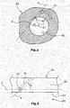
- the sample inlet opening 40 is provided with an opening axis a which is inclined with respect to the inlet cross plane h with an inclination angle A2 of about 60°, as only schematically shown in figure 3 . Additionally, the inlet opening axis a is angled with respect to the radial line r of the cylindrical vial head surface 32 with a tangency angle A1 of more than 30°, preferably of more than 45°, and more preferably as close to 90° as possible.
- the liquid sample is flowing through the inlet opening 40 into the sample volume 18 with a tangential flow vector which is directed downwardly so that the liquid current flows along the cylindrical vial surface 22 in a helical line with a total rotational angle of about 200° down to the vial bottom wall 23 where the liquid flow is reflected and decelerated so that the liquid flows back upwardly in a center column of the liquid sample 19.
- the liquid flow then arrives at the conical light trap body 36 and is thereby forced to flow radially outwardly, and is finally leaving the sample volume 18 via the sample outlet opening 50 and the outlet conduct 51.
- the cylinder diameter D20,D30 of the lateral vial surface 22 and of the lateral head surface 32 is about 15 to 16 mm.
- the total axial length of the sample volume 18 is about 80 mm so that the total volume of the sample volume 18 is about 14000 mm 3 .
- the current speed of the inflowing liquid is highest such that the current speed of the liquid in all regions of the sample volume 18 is larger than the settling speed of a sand particle of, for example, 50 ⁇ m.
- a sand particle of 50 ⁇ m is always carried away with the liquid current and cannot settle at the bottom wall 23 of the sample vial 20.
- the current speed of the inflowing liquid is adapted so as to allow the liquid to flow downwardly at the radial outside along the vial surface 22 of the sample vial 20 and to flow upwardly in the center.
Landscapes
- Chemical & Material Sciences (AREA)
- General Health & Medical Sciences (AREA)
- Life Sciences & Earth Sciences (AREA)
- Health & Medical Sciences (AREA)
- Analytical Chemistry (AREA)
- Biochemistry (AREA)
- Physics & Mathematics (AREA)
- General Physics & Mathematics (AREA)
- Immunology (AREA)
- Pathology (AREA)
- Dispersion Chemistry (AREA)
- Optical Measuring Cells (AREA)
- Investigating Or Analysing Materials By Optical Means (AREA)
Description
- The present invention refers to a nephelometric process turbidimeter for continuously or quasi-continuously measuring the turbidity of a liquid sample, for example drinking water, in a transparent sample vial.
- A nephelometric turbidimeter determines the concentration of solid particles suspended in a liquid sample within a sample vial by projecting a measurement light beam into the liquid sample within the vial. An optical turbidity sensor which is provided outside the cuvette body detects the amount of light scattered by the suspended solid particles at an angle of typically 90° with respect to the light beam axis. In a process turbidimeter the liquid sample within the sample volume defined by the sample vial is exchanged continuously, quasi-continuously or periodically to continuously supply a control circuit with turbidity values for controlling the turbidity of the liquid. The measurement frequency or response time of the turbidimeter is defined by the sample exchange time which is the time which is needed to completely exchange the sample within the vial in a defined grade as, for example, by 99%. The higher the measurement frequency of the turbidimeter is, the shorter is the reaction time of the control circuit, and the shorter the reaction time of the control circuit is, the better is the control quality of the control circuit.
- In a state of the art nephelometric process turbidimeter, a separate vial head is provided on the vial opening to thereby define, together with the sample vial, a closed sample volume. The vial head is provided with a sample inlet opening and a sample outlet opening, both being located at the end wall of the vial head, the end wall lying in a cross plane with respect to the longitudinal axis of the cylindrical sample vial. The sample exchange time of this arrangement ranges from 30 to 120 seconds.
- It is an object of the invention to provide a nephelometric process turbidimeter for measuring the turbidity of a liquid sample with a decreased sample exchange time.
-
US 5 446 544 A discloses a turbidimeter with a sample vial and a separate vial head, both defining a sample volume for the liquid sample, wherein the lateral inner surface of the sample volume is cylindrical. The sample inlet opening through which the liquid sample flows into the sample volume and a sample outlet opening through which the liquid sample flows out of the sample volume, are both provided at the vial head. -
WO 88/02855 A1 - This object is solved with a nephelometric process turbidimeter with the features of claim 1.
- The transparent sample vial and the separate vial head both define the sample volume for the liquid sample. The lateral inner surface of the sample volume is cylindrical. The sample inlet opening through which the liquid sample flows into the sample volume as well as the sample outlet opening through which the liquid sample flows out of the sample volume are both provided at the vial head. According to the invention, the sample inlet opening is not arranged at the top surface of the vial head, but is arranged at the cylindrical lateral surface of the vial head. The sample inlet opening is arranged axially closer to the sample vial than the sample outlet opening, so that the inlet opening is arranged below the outlet opening if the sample vial and the vial head are standing vertically upright.
- The inlet opening axis of the sample inlet opening is the spatial middle axis of the sample outlet duct, and thereby is identical with the current flow vector of the liquid flowing out of the sample inlet opening into the sample volume. The inlet opening axis is not orientated at a right angle with respect to the plane of the inlet opening because the inlet opening is tapered.
- The inlet opening axis of the sample inlet opening is inclined with respect to the inlet cross plane with an inclination angle of 10° to 80°. The inlet cross plane is a plane arranged in a right angle with respect to the longitudinal axis defined by the sample volume cylinder. In other words, the sample inlet opening is orientated with a vertical component in the direction of the sample vial so that the flow vector of the liquid flowing into the sample volume has a vertical component.
- The inlet opening axis is also angled with respect to the radius line of the cylinder with a tangency angle of more than 15° so that the flow vector of the liquid flowing into the sample volume has a tangency component or is orientated exactly tangentially which would correspond to a tangency angle of about 90°.
- As a result, the liquid flowing into the sample volume flows to the bottom of the sample vial in a helical line along the lateral inner surface of the sample volume. The flow impulse of the liquid is reflected backwardly and reduced at the bottom wall of the sample vial so that the liquid flows back in the direction of the vial head through the center region of the sample volume. The sample outlet opening is, seen in the direction of the back-flowing liquid, arranged behind the sample inlet opening so that the liquid can expand radially outwardly behind the sample inlet opening without colliding with the liquid flowing into the sample volume through the sample inlet opening.
- Experiments have shown that this arrangement of the sample inlet opening and the sample outlet opening allows to considerably decrease the sample exchange interval to less than 20-30 seconds. The short sample exchange interval results in an increased measurement frequency so that the reaction time is decreased and the control quality of the control circuit is improved accordingly.
- According to a preferred embodiment of the invention, the vial head is provided with a light-trap structure and the sample inlet opening is arranged axially beyond the light-trap structure. The light-trap structure is arranged opposite to the bottom wall of the sample vial and is in particular advantageous if the measurement beam is directed axially through the vial bottom wall into the sample volume. Generally, the light-trap structure can be realized in many different ways. But many light-trap structures extend axially from the axial end of the vial head into the sample volume so that the fluidic cross sectional area is reduced by the light-trap structure. As a consequence, the back-flowing sample liquid can be forced radially outwardly by the light-trap structure. Since the sample inlet opening is arranged axially beyond the light trap structure, i.e. with an axial distance to the light-trap structure, the back-flowing sample liquid current does not collide with the in-flowing sample liquid current.
- Preferably, the light-trap structure is a conical light-trap body extending axially from the axial end of the vial head. The conical angle of the light-trap body with respect to the longitudinal axis is preferably smaller than 45°. The sample inlet opening is preferably arranged axially beyond the tip of the conical light-trap body, seen from the sample outlet opening.
- The conical light-trap body is an efficient light-trap structure and also allows a laminar axial flow of the back-flowing sample liquid current along the light-trap cone. The steeper the cone is, the better are the light-trapping effect and the laminar flow quality of the liquid flowing along the cone.
- According to a preferred embodiment of the invention, the sample outlet opening is arranged at the axial top end of the sample volume. If the light-trap structure is provided as a cone, the outlet opening is provided in the basic plane of the cone and adjacent to the cone basis. If no light-trap structure is provided and the axial end of the vial head is provided as a plane end wall, the sample outlet opening can be arranged in the middle of the end wall.
- Preferably, the inner surface of the vial head is completely black and mat to improve the light-absorbing quality of the vial head.
- According to a preferred embodiment of the invention, the diameter of the cylindrical sample volume is 5 mm to 30 mm, and preferably is 10 mm to 20 mm, so that the diameter of the cylindrical sample volume is relatively small. Since the diameter of the cylindrical sample volume is relatively small, the total volume of the sample volume is reduced significantly. As a consequence, the sample exchange interval is also reduced significantly. Preferably, the inclination angle of the inlet opening axis is between 45° and 75°. The inclination angle preferably is chosen so as to cause a screw-like or helical sample current path down to the bottom wall of the sample vial with a rotational angle of at most 250° to 200° so that the inflowing sample current does not collide with itself. The rotational angle is affected by the longitudinal length of the vial and the inclination angle and is also slightly affected by the liquid current inlet speed.
- Preferably, the axial distance of the sample inlet opening to the bottom wall of the sample vial is more than 30 mm and is preferably less than 150 mm. The axial distance should be as low as possible to avoid that the helical sample current extends a total rotational angle of more than 250° to 200° to avoid that the inflowing sample current collides with itself.
- One embodiment of the invention is described with reference to the enclosed drawings, wherein
-
figure 1 shows a process turbidimeter with a sample volume defined by a sample vial and a vial head with a sample inlet opening and a sample outlet opening provided at the vial head, -
figure 2 a cross section of the inlet opening plane II-II offigure 1 , andfigure 3 the unfolded lateral surface of the vial head. -
Figure 1 shows a schematically anephelometric process turbidimeter 10 for quasi-continuously measuring the turbidity of aliquid sample 19, for example of drinking water. - The
turbidimeter 10 is provided with a transparent andcylindrical sample vial 20 and a non-transparentvial head 30 closing the top opening of thesample vial 20. Thevial head 30 and thesample vial 20 together enclose and define asample volume 18 which is completely filled with theliquid sample 19. Thelateral surface 22 of thesample vial 20 and thelateral surface 32 of thevial head 30 are both cylindrical and have the same diameter D20,D30 so that they together define acylindrical sample volume 18 with a longitudinalsample volume axis 21 preferably being orientated vertically. - The cup-
shaped sample vial 20 is provided with a plane andtransparent bottom wall 23 lying in a cross plane with respect to the longitudinalsample volume axis 21. Ameasurement light source 12 is arranged outside thesample vial 20 under thebottom wall 23. Thelight source 12 generates alight beam 25 which is substantially axially directed through thevial bottom wall 23 into theliquid sample 19. Thelight beam 25 is scattered by particles of theliquid sample 19, and a part of the scattered light is collected and reflected by aring prism 14 reflecting the scattered light to alight detector 16. - The
vial head 30 is made out of black plastic and is provided with a mat black inside surface. At the axial end portion of thevial head 30, thevial head 30 is provided with a light-trap structure 34 which is defined by a conical light-trap body 36. The cone angle between the conical surface of the light-trap body 36 and the longitudinalsample volume axis 21 is 45° at the most, and is preferably less than 45°. The axial height H3 of the conical light-trap body 36 with respect to the axial end portion of thevial head 30 is about 15 mm. - The
vial head 30 is provided with asample inlet conduit 41 with a sample inlet opening 40 through which the liquid sample continuously flows into thesample volume 18 and is provided with asample outlet conduit 51 with a sample outlet opening 50 through which the liquid sample flows out of thesample volume 18. The sample inlet opening 40 is arranged at thecylindrical surface 32 of thevial head 30 and the sample outlet opening is arranged at the axial top end of thesample volume 18 and adjacent to the base of the conical light-trap body 36. - The sample inlet opening 40 is arranged axially beyond the light-
trap structure 34 with a longitudinal opening offset H2 of 20mm with respect to the axial end portion of thevial head 30. The longitudinal opening offset H2 is larger than the axial height H3 of the conical light-trap body 36 so that the sample inlet opening 40 is arranged with an axial distance from thesample outlet opening 50 and does not laterally overlap with the light-trap structure 34. In other words, the sample inlet opening 40 is arranged axially closer to thesample vial 20 then thesample outlet opening 50 and the cone tip. - The orientation of the sample outlet opening axis is vertical so that the outlet current vector is orientated vertically. The sample inlet opening 40 is provided with an opening axis a which is inclined with respect to the inlet cross plane h with an inclination angle A2 of about 60°, as only schematically shown in
figure 3 . Additionally, the inlet opening axis a is angled with respect to the radial line r of the cylindricalvial head surface 32 with a tangency angle A1 of more than 30°, preferably of more than 45°, and more preferably as close to 90° as possible. - The liquid sample is flowing through the inlet opening 40 into the
sample volume 18 with a tangential flow vector which is directed downwardly so that the liquid current flows along thecylindrical vial surface 22 in a helical line with a total rotational angle of about 200° down to thevial bottom wall 23 where the liquid flow is reflected and decelerated so that the liquid flows back upwardly in a center column of theliquid sample 19. The liquid flow then arrives at the conicallight trap body 36 and is thereby forced to flow radially outwardly, and is finally leaving thesample volume 18 via thesample outlet opening 50 and theoutlet conduct 51. - The cylinder diameter D20,D30 of the
lateral vial surface 22 and of thelateral head surface 32 is about 15 to 16 mm. The total axial length of thesample volume 18 is about 80 mm so that the total volume of thesample volume 18 is about 14000 mm3. - The current speed of the inflowing liquid is highest such that the current speed of the liquid in all regions of the
sample volume 18 is larger than the settling speed of a sand particle of, for example, 50 µm. As a consequence, a sand particle of 50 µm is always carried away with the liquid current and cannot settle at thebottom wall 23 of thesample vial 20. The current speed of the inflowing liquid is adapted so as to allow the liquid to flow downwardly at the radial outside along thevial surface 22 of thesample vial 20 and to flow upwardly in the center.
Claims (8)
- A nephelometric process turbidimeter (10) for measuring a turbidity of a liquid sample (19), the turbidimeter (10) comprising:a transparent sample vial (20) and a separate vial head (30), both defining a sample volume (18) for the liquid sample (19), wherein the lateral inner surface (22, 32) of the sample volume (18) is cylindrical, and an inlet cross plane (h) being defined by a plane arranged in a right angle with respect to a longitudinal axis of the cylindrical sample volume (18),a sample inlet opening (40) through which the liquid sample flows into the sample volume (18) and a sample outlet opening (50) through which the liquid sample flows out of the sample volume (18), both openings (40, 50) being provided at the vial head (30),characterised bythe sample inlet opening (40) being arranged at the cylindrical surface (32) of the vial head (30) and being arranged axially closer to the sample vial (20) than the sample outlet opening (50), whereinthe inlet opening axis (a) of the sample inlet opening (40) is inclined with respect to the inlet cross plane (h) with a inclination angle (A2) of 10° to 80° and is angled with respect to the radius (r) with a tangency angle (A1) of more than 15°.
- The nephelometric process turbidimeter (10) of claim 1, wherein the vial head (30) is provided with a light-trap structure (34) and the sample inlet opening (40) is arranged axially beyond the light-trap structure (34).
- The nephelometric process turbidimeter (10) of claim 2, wherein the light trap structure (34) is an axial conical light trap body (36).
- The nephelometric process turbidimeter (10) of one of the preceding claims, wherein the sample outlet opening (50) is arranged at the axial end of the sample volume (18).
- The nephelometric process turbidimeter (10) of one of the preceding claims, wherein the inner surface of the vial head (30) is black.
- The nephelometric process turbidimeter (10) of one of the preceding claims, wherein the diameter of the cylindrical sample volume (18) is 5-30 mm, preferably 10-20 mm.
- The nephelometric process turbidimeter (10) of one of the preceding claims, wherein in the distance (H1) of the sample inlet opening (40) to a bottom wall (23) of the sample vial (20) is more than 30 mm.
- The nephelometric process turbidimeter (10) of one of the preceding claims, wherein the inclination angle (A2) of the inlet opening axis (a) is between 45° and 75°.
Priority Applications (6)
| Application Number | Priority Date | Filing Date | Title |
|---|---|---|---|
| EP14195057.6A EP3026421B1 (en) | 2014-11-27 | 2014-11-27 | A nephelometric process turbidimeter |
| CA2913084A CA2913084C (en) | 2014-11-27 | 2015-11-24 | A nephelometric process turbidimeter |
| CN201510830307.9A CN105651734B (en) | 2014-11-27 | 2015-11-25 | Scattering formula process nephelometer |
| US14/951,501 US9546944B2 (en) | 2014-11-27 | 2015-11-25 | Nephelometric process turbidimeter |
| BR102015029692-4A BR102015029692B1 (en) | 2014-11-27 | 2015-11-26 | NEBELOMETRIC PROCESS TURBIDIMETER TO MEASURE A TURBIDITY OF A LIQUID SAMPLE |
| JP2015232010A JP6645815B2 (en) | 2014-11-27 | 2015-11-27 | Turbidimetry for process turbidimetry |
Applications Claiming Priority (1)
| Application Number | Priority Date | Filing Date | Title |
|---|---|---|---|
| EP14195057.6A EP3026421B1 (en) | 2014-11-27 | 2014-11-27 | A nephelometric process turbidimeter |
Publications (2)
| Publication Number | Publication Date |
|---|---|
| EP3026421A1 EP3026421A1 (en) | 2016-06-01 |
| EP3026421B1 true EP3026421B1 (en) | 2017-05-03 |
Family
ID=51987047
Family Applications (1)
| Application Number | Title | Priority Date | Filing Date |
|---|---|---|---|
| EP14195057.6A Active EP3026421B1 (en) | 2014-11-27 | 2014-11-27 | A nephelometric process turbidimeter |
Country Status (6)
| Country | Link |
|---|---|
| US (1) | US9546944B2 (en) |
| EP (1) | EP3026421B1 (en) |
| JP (1) | JP6645815B2 (en) |
| CN (1) | CN105651734B (en) |
| BR (1) | BR102015029692B1 (en) |
| CA (1) | CA2913084C (en) |
Families Citing this family (3)
| Publication number | Priority date | Publication date | Assignee | Title |
|---|---|---|---|---|
| EP3026424A1 (en) * | 2014-11-27 | 2016-06-01 | Hach Lange GmbH | Nephelometric turbidimeter using a labeled cuvette |
| US11435277B2 (en) * | 2015-10-20 | 2022-09-06 | Tintometer, Gmbh | Device for removing energy from a beam and a method(s) of use thereof |
| SG11202103776YA (en) * | 2018-12-03 | 2021-05-28 | Sirtex Medical Inc | Apparatus for delivery of radioembolization microspheres |
Family Cites Families (24)
| Publication number | Priority date | Publication date | Assignee | Title |
|---|---|---|---|---|
| DE3027317C2 (en) * | 1980-07-18 | 1982-06-16 | Hans 8400 Regensburg Krause | Flow fluorometer |
| JPS5739337A (en) * | 1980-08-20 | 1982-03-04 | Toshiba Corp | Turbidimeter |
| US4432642A (en) * | 1981-10-06 | 1984-02-21 | Tolles Walter E | Nephelometer |
| JPS61189252U (en) * | 1985-05-17 | 1986-11-26 | ||
| GB8624587D0 (en) * | 1986-10-14 | 1986-11-19 | North Sea Instr Ltd | Particle analysis apparatus |
| CN86210309U (en) * | 1986-12-18 | 1987-08-26 | 西南师范大学 | Turbidity meter |
| JPS6413436A (en) * | 1987-07-08 | 1989-01-18 | Hitachi Ltd | Cell for photodetection |
| EP0608309A4 (en) * | 1991-10-14 | 1994-09-14 | Iei Pty Ltd | Improvements relating to a sampling chamber for a pollution detector. |
| CN2143330Y (en) * | 1992-10-14 | 1993-10-06 | 王志武 | Desk turbidimeter |
| US5446544A (en) * | 1993-01-22 | 1995-08-29 | Hf Scientific, Inc. | Turbidimeter |
| US5574232A (en) * | 1995-06-01 | 1996-11-12 | Robert Davidson | Liquid sample flow-through analysis cell |
| JP2002181690A (en) * | 2000-12-15 | 2002-06-26 | Horiba Ltd | Particle diameter distribution measuring apparatus |
| US7046347B1 (en) * | 2001-03-30 | 2006-05-16 | Amend John R | Instrument with colorimeter and sensor inputs for interfacing with a computer |
| CN2514351Y (en) * | 2001-12-20 | 2002-10-02 | 孙墨杰 | Batch-type on-line automatic washing turbidimeter |
| AU2003213294A1 (en) * | 2002-02-25 | 2003-09-09 | Waters Investments Limited | An opaque additive to block stray light in teflon af light-guiding flowcells |
| JP2004245612A (en) * | 2003-02-10 | 2004-09-02 | Horiba Ltd | Apparatus for measuring particle size distribution |
| US7658884B2 (en) * | 2005-10-05 | 2010-02-09 | Swan Analytische Instrumente Ag | Photometric method and apparatus for measuring a liquid's turbidity, fluorescence, phosphorescence and/or absorption coefficient |
| KR20090098453A (en) * | 2008-03-14 | 2009-09-17 | 삼성전자주식회사 | Turbidity sensor and home appliances |
| JP4675406B2 (en) * | 2008-09-29 | 2011-04-20 | 日本分光株式会社 | Sample collection container, sample collection device, and sample collection method in a supercritical fluid system |
| US7659980B1 (en) * | 2008-11-24 | 2010-02-09 | Herbert Leckie Mitchell | Nephelometric turbidity sensor device |
| JP2012132750A (en) * | 2010-12-21 | 2012-07-12 | Sharp Corp | Turbidity meter |
| WO2015043675A1 (en) * | 2013-09-30 | 2015-04-02 | Hach Lange Gmbh | Nephelometric turbidimeter and method for detection of the contamination of a sample cuvette of a nephelometric turbidimeter |
| EP3026424A1 (en) * | 2014-11-27 | 2016-06-01 | Hach Lange GmbH | Nephelometric turbidimeter using a labeled cuvette |
| EP3705873B1 (en) * | 2014-11-27 | 2022-10-12 | Hach Lange GmbH | Nephelometric turbidimeter vial arrangement |
-
2014
- 2014-11-27 EP EP14195057.6A patent/EP3026421B1/en active Active
-
2015
- 2015-11-24 CA CA2913084A patent/CA2913084C/en active Active
- 2015-11-25 US US14/951,501 patent/US9546944B2/en active Active
- 2015-11-25 CN CN201510830307.9A patent/CN105651734B/en active Active
- 2015-11-26 BR BR102015029692-4A patent/BR102015029692B1/en active IP Right Grant
- 2015-11-27 JP JP2015232010A patent/JP6645815B2/en active Active
Also Published As
| Publication number | Publication date |
|---|---|
| EP3026421A1 (en) | 2016-06-01 |
| US9546944B2 (en) | 2017-01-17 |
| JP2016105089A (en) | 2016-06-09 |
| JP6645815B2 (en) | 2020-02-14 |
| BR102015029692B1 (en) | 2021-04-13 |
| CA2913084A1 (en) | 2016-05-27 |
| US20160153886A1 (en) | 2016-06-02 |
| CN105651734B (en) | 2018-06-12 |
| CA2913084C (en) | 2018-07-31 |
| BR102015029692A2 (en) | 2016-06-14 |
| CN105651734A (en) | 2016-06-08 |
Similar Documents
| Publication | Publication Date | Title |
|---|---|---|
| US8678204B2 (en) | Centrifugal separator | |
| CA2687349C (en) | Induced vortex particle separator | |
| CA2913084C (en) | A nephelometric process turbidimeter | |
| CN103347580A (en) | Multi-chambered hydroclone | |
| RU2666883C1 (en) | Dust collector with fire and explosion safety system | |
| EP2626139A1 (en) | Cyclone separator for gas liquid separation | |
| SE535756C2 (en) | Flow deflector for hydrocyclone | |
| UA127498C2 (en) | Hydrocyclone separator | |
| CN102802756B (en) | Filter | |
| RU2008117464A (en) | METHOD AND DEVICE FOR THICKENING Sludge Transported With Wastewater | |
| KR20180022758A (en) | Dual cyclone type processing apparatus of suspened solids | |
| JP2016511140A (en) | Centrifuge with stretched struts | |
| RU2367523C1 (en) | Cyclone | |
| JP2008119694A (en) | Horizontal dust remover | |
| WO2020040705A1 (en) | Solid-liquid separator | |
| RU2668028C1 (en) | Dust collector with fire and explosion safety system | |
| RU176513U1 (en) | DUST CATCHER CLASSIFIER | |
| JP2018533479A (en) | Cyclone system | |
| US9687760B2 (en) | Separation devices, systems and methods for separation of particulates from liquid | |
| KR20020029329A (en) | Improved injection of a solids-laden water stream into a centrifugal separator | |
| US7374672B2 (en) | Filter device comprising integral centrifugal separation | |
| RU2545559C1 (en) | Gas treatment centrifuge | |
| JP2015020083A (en) | Defoaming device and liquid analyzer | |
| RU2302907C2 (en) | Hydraulic cyclone | |
| JP2009018278A (en) | Cyclone type filtering apparatus |
Legal Events
| Date | Code | Title | Description |
|---|---|---|---|
| PUAI | Public reference made under article 153(3) epc to a published international application that has entered the european phase |
Free format text: ORIGINAL CODE: 0009012 |
|
| 17P | Request for examination filed |
Effective date: 20150701 |
|
| AK | Designated contracting states |
Kind code of ref document: A1 Designated state(s): AL AT BE BG CH CY CZ DE DK EE ES FI FR GB GR HR HU IE IS IT LI LT LU LV MC MK MT NL NO PL PT RO RS SE SI SK SM TR |
|
| AX | Request for extension of the european patent |
Extension state: BA ME |
|
| GRAP | Despatch of communication of intention to grant a patent |
Free format text: ORIGINAL CODE: EPIDOSNIGR1 |
|
| STAA | Information on the status of an ep patent application or granted ep patent |
Free format text: STATUS: GRANT OF PATENT IS INTENDED |
|
| INTG | Intention to grant announced |
Effective date: 20170125 |
|
| GRAS | Grant fee paid |
Free format text: ORIGINAL CODE: EPIDOSNIGR3 |
|
| GRAA | (expected) grant |
Free format text: ORIGINAL CODE: 0009210 |
|
| STAA | Information on the status of an ep patent application or granted ep patent |
Free format text: STATUS: THE PATENT HAS BEEN GRANTED |
|
| AK | Designated contracting states |
Kind code of ref document: B1 Designated state(s): AL AT BE BG CH CY CZ DE DK EE ES FI FR GB GR HR HU IE IS IT LI LT LU LV MC MK MT NL NO PL PT RO RS SE SI SK SM TR |
|
| REG | Reference to a national code |
Ref country code: GB Ref legal event code: FG4D |
|
| REG | Reference to a national code |
Ref country code: AT Ref legal event code: REF Ref document number: 890524 Country of ref document: AT Kind code of ref document: T Effective date: 20170515 Ref country code: CH Ref legal event code: EP |
|
| REG | Reference to a national code |
Ref country code: IE Ref legal event code: FG4D |
|
| REG | Reference to a national code |
Ref country code: DE Ref legal event code: R096 Ref document number: 602014009248 Country of ref document: DE |
|
| REG | Reference to a national code |
Ref country code: NL Ref legal event code: MP Effective date: 20170503 |
|
| REG | Reference to a national code |
Ref country code: AT Ref legal event code: MK05 Ref document number: 890524 Country of ref document: AT Kind code of ref document: T Effective date: 20170503 |
|
| REG | Reference to a national code |
Ref country code: LT Ref legal event code: MG4D |
|
| PG25 | Lapsed in a contracting state [announced via postgrant information from national office to epo] |
Ref country code: HR Free format text: LAPSE BECAUSE OF FAILURE TO SUBMIT A TRANSLATION OF THE DESCRIPTION OR TO PAY THE FEE WITHIN THE PRESCRIBED TIME-LIMIT Effective date: 20170503 Ref country code: NO Free format text: LAPSE BECAUSE OF FAILURE TO SUBMIT A TRANSLATION OF THE DESCRIPTION OR TO PAY THE FEE WITHIN THE PRESCRIBED TIME-LIMIT Effective date: 20170803 Ref country code: FI Free format text: LAPSE BECAUSE OF FAILURE TO SUBMIT A TRANSLATION OF THE DESCRIPTION OR TO PAY THE FEE WITHIN THE PRESCRIBED TIME-LIMIT Effective date: 20170503 Ref country code: AT Free format text: LAPSE BECAUSE OF FAILURE TO SUBMIT A TRANSLATION OF THE DESCRIPTION OR TO PAY THE FEE WITHIN THE PRESCRIBED TIME-LIMIT Effective date: 20170503 Ref country code: ES Free format text: LAPSE BECAUSE OF FAILURE TO SUBMIT A TRANSLATION OF THE DESCRIPTION OR TO PAY THE FEE WITHIN THE PRESCRIBED TIME-LIMIT Effective date: 20170503 Ref country code: GR Free format text: LAPSE BECAUSE OF FAILURE TO SUBMIT A TRANSLATION OF THE DESCRIPTION OR TO PAY THE FEE WITHIN THE PRESCRIBED TIME-LIMIT Effective date: 20170804 Ref country code: LT Free format text: LAPSE BECAUSE OF FAILURE TO SUBMIT A TRANSLATION OF THE DESCRIPTION OR TO PAY THE FEE WITHIN THE PRESCRIBED TIME-LIMIT Effective date: 20170503 |
|
| REG | Reference to a national code |
Ref country code: FR Ref legal event code: PLFP Year of fee payment: 4 |
|
| PG25 | Lapsed in a contracting state [announced via postgrant information from national office to epo] |
Ref country code: PL Free format text: LAPSE BECAUSE OF FAILURE TO SUBMIT A TRANSLATION OF THE DESCRIPTION OR TO PAY THE FEE WITHIN THE PRESCRIBED TIME-LIMIT Effective date: 20170503 Ref country code: SE Free format text: LAPSE BECAUSE OF FAILURE TO SUBMIT A TRANSLATION OF THE DESCRIPTION OR TO PAY THE FEE WITHIN THE PRESCRIBED TIME-LIMIT Effective date: 20170503 Ref country code: RS Free format text: LAPSE BECAUSE OF FAILURE TO SUBMIT A TRANSLATION OF THE DESCRIPTION OR TO PAY THE FEE WITHIN THE PRESCRIBED TIME-LIMIT Effective date: 20170503 Ref country code: NL Free format text: LAPSE BECAUSE OF FAILURE TO SUBMIT A TRANSLATION OF THE DESCRIPTION OR TO PAY THE FEE WITHIN THE PRESCRIBED TIME-LIMIT Effective date: 20170503 Ref country code: LV Free format text: LAPSE BECAUSE OF FAILURE TO SUBMIT A TRANSLATION OF THE DESCRIPTION OR TO PAY THE FEE WITHIN THE PRESCRIBED TIME-LIMIT Effective date: 20170503 Ref country code: BG Free format text: LAPSE BECAUSE OF FAILURE TO SUBMIT A TRANSLATION OF THE DESCRIPTION OR TO PAY THE FEE WITHIN THE PRESCRIBED TIME-LIMIT Effective date: 20170803 Ref country code: IS Free format text: LAPSE BECAUSE OF FAILURE TO SUBMIT A TRANSLATION OF THE DESCRIPTION OR TO PAY THE FEE WITHIN THE PRESCRIBED TIME-LIMIT Effective date: 20170903 |
|
| PG25 | Lapsed in a contracting state [announced via postgrant information from national office to epo] |
Ref country code: SK Free format text: LAPSE BECAUSE OF FAILURE TO SUBMIT A TRANSLATION OF THE DESCRIPTION OR TO PAY THE FEE WITHIN THE PRESCRIBED TIME-LIMIT Effective date: 20170503 Ref country code: EE Free format text: LAPSE BECAUSE OF FAILURE TO SUBMIT A TRANSLATION OF THE DESCRIPTION OR TO PAY THE FEE WITHIN THE PRESCRIBED TIME-LIMIT Effective date: 20170503 Ref country code: CZ Free format text: LAPSE BECAUSE OF FAILURE TO SUBMIT A TRANSLATION OF THE DESCRIPTION OR TO PAY THE FEE WITHIN THE PRESCRIBED TIME-LIMIT Effective date: 20170503 Ref country code: RO Free format text: LAPSE BECAUSE OF FAILURE TO SUBMIT A TRANSLATION OF THE DESCRIPTION OR TO PAY THE FEE WITHIN THE PRESCRIBED TIME-LIMIT Effective date: 20170503 Ref country code: DK Free format text: LAPSE BECAUSE OF FAILURE TO SUBMIT A TRANSLATION OF THE DESCRIPTION OR TO PAY THE FEE WITHIN THE PRESCRIBED TIME-LIMIT Effective date: 20170503 |
|
| REG | Reference to a national code |
Ref country code: DE Ref legal event code: R097 Ref document number: 602014009248 Country of ref document: DE |
|
| PG25 | Lapsed in a contracting state [announced via postgrant information from national office to epo] |
Ref country code: IT Free format text: LAPSE BECAUSE OF FAILURE TO SUBMIT A TRANSLATION OF THE DESCRIPTION OR TO PAY THE FEE WITHIN THE PRESCRIBED TIME-LIMIT Effective date: 20170503 Ref country code: SM Free format text: LAPSE BECAUSE OF FAILURE TO SUBMIT A TRANSLATION OF THE DESCRIPTION OR TO PAY THE FEE WITHIN THE PRESCRIBED TIME-LIMIT Effective date: 20170503 |
|
| PLBE | No opposition filed within time limit |
Free format text: ORIGINAL CODE: 0009261 |
|
| STAA | Information on the status of an ep patent application or granted ep patent |
Free format text: STATUS: NO OPPOSITION FILED WITHIN TIME LIMIT |
|
| 26N | No opposition filed |
Effective date: 20180206 |
|
| PG25 | Lapsed in a contracting state [announced via postgrant information from national office to epo] |
Ref country code: SI Free format text: LAPSE BECAUSE OF FAILURE TO SUBMIT A TRANSLATION OF THE DESCRIPTION OR TO PAY THE FEE WITHIN THE PRESCRIBED TIME-LIMIT Effective date: 20170503 |
|
| PG25 | Lapsed in a contracting state [announced via postgrant information from national office to epo] |
Ref country code: MC Free format text: LAPSE BECAUSE OF FAILURE TO SUBMIT A TRANSLATION OF THE DESCRIPTION OR TO PAY THE FEE WITHIN THE PRESCRIBED TIME-LIMIT Effective date: 20170503 |
|
| PG25 | Lapsed in a contracting state [announced via postgrant information from national office to epo] |
Ref country code: LI Free format text: LAPSE BECAUSE OF NON-PAYMENT OF DUE FEES Effective date: 20171130 Ref country code: CH Free format text: LAPSE BECAUSE OF NON-PAYMENT OF DUE FEES Effective date: 20171130 |
|
| PG25 | Lapsed in a contracting state [announced via postgrant information from national office to epo] |
Ref country code: LU Free format text: LAPSE BECAUSE OF NON-PAYMENT OF DUE FEES Effective date: 20171127 |
|
| REG | Reference to a national code |
Ref country code: BE Ref legal event code: MM Effective date: 20171130 |
|
| REG | Reference to a national code |
Ref country code: IE Ref legal event code: MM4A |
|
| PG25 | Lapsed in a contracting state [announced via postgrant information from national office to epo] |
Ref country code: MT Free format text: LAPSE BECAUSE OF NON-PAYMENT OF DUE FEES Effective date: 20171127 |
|
| PG25 | Lapsed in a contracting state [announced via postgrant information from national office to epo] |
Ref country code: IE Free format text: LAPSE BECAUSE OF NON-PAYMENT OF DUE FEES Effective date: 20171127 |
|
| PG25 | Lapsed in a contracting state [announced via postgrant information from national office to epo] |
Ref country code: BE Free format text: LAPSE BECAUSE OF NON-PAYMENT OF DUE FEES Effective date: 20171130 |
|
| PG25 | Lapsed in a contracting state [announced via postgrant information from national office to epo] |
Ref country code: HU Free format text: LAPSE BECAUSE OF FAILURE TO SUBMIT A TRANSLATION OF THE DESCRIPTION OR TO PAY THE FEE WITHIN THE PRESCRIBED TIME-LIMIT; INVALID AB INITIO Effective date: 20141127 |
|
| PG25 | Lapsed in a contracting state [announced via postgrant information from national office to epo] |
Ref country code: CY Free format text: LAPSE BECAUSE OF FAILURE TO SUBMIT A TRANSLATION OF THE DESCRIPTION OR TO PAY THE FEE WITHIN THE PRESCRIBED TIME-LIMIT Effective date: 20170503 |
|
| PG25 | Lapsed in a contracting state [announced via postgrant information from national office to epo] |
Ref country code: MK Free format text: LAPSE BECAUSE OF FAILURE TO SUBMIT A TRANSLATION OF THE DESCRIPTION OR TO PAY THE FEE WITHIN THE PRESCRIBED TIME-LIMIT Effective date: 20170503 |
|
| REG | Reference to a national code |
Ref country code: DE Ref legal event code: R082 Ref document number: 602014009248 Country of ref document: DE Representative=s name: TERPATENT PARTGMBB, DE Ref country code: DE Ref legal event code: R082 Ref document number: 602014009248 Country of ref document: DE Representative=s name: TERPATENT PATENTANWAELTE TER SMITTEN EBERLEIN-, DE |
|
| PG25 | Lapsed in a contracting state [announced via postgrant information from national office to epo] |
Ref country code: TR Free format text: LAPSE BECAUSE OF FAILURE TO SUBMIT A TRANSLATION OF THE DESCRIPTION OR TO PAY THE FEE WITHIN THE PRESCRIBED TIME-LIMIT Effective date: 20170503 |
|
| PG25 | Lapsed in a contracting state [announced via postgrant information from national office to epo] |
Ref country code: PT Free format text: LAPSE BECAUSE OF FAILURE TO SUBMIT A TRANSLATION OF THE DESCRIPTION OR TO PAY THE FEE WITHIN THE PRESCRIBED TIME-LIMIT Effective date: 20170503 |
|
| PG25 | Lapsed in a contracting state [announced via postgrant information from national office to epo] |
Ref country code: AL Free format text: LAPSE BECAUSE OF FAILURE TO SUBMIT A TRANSLATION OF THE DESCRIPTION OR TO PAY THE FEE WITHIN THE PRESCRIBED TIME-LIMIT Effective date: 20170503 |
|
| PGFP | Annual fee paid to national office [announced via postgrant information from national office to epo] |
Ref country code: DE Payment date: 20251119 Year of fee payment: 12 |
|
| PGFP | Annual fee paid to national office [announced via postgrant information from national office to epo] |
Ref country code: GB Payment date: 20251121 Year of fee payment: 12 |
|
| PGFP | Annual fee paid to national office [announced via postgrant information from national office to epo] |
Ref country code: FR Payment date: 20251125 Year of fee payment: 12 |