EP3026414A1 - Testing device for thin-walled large bearing - Google Patents
Testing device for thin-walled large bearing Download PDFInfo
- Publication number
- EP3026414A1 EP3026414A1 EP14830127.8A EP14830127A EP3026414A1 EP 3026414 A1 EP3026414 A1 EP 3026414A1 EP 14830127 A EP14830127 A EP 14830127A EP 3026414 A1 EP3026414 A1 EP 3026414A1
- Authority
- EP
- European Patent Office
- Prior art keywords
- bearing
- face board
- general
- thin
- purpose frame
- Prior art date
- Legal status (The legal status is an assumption and is not a legal conclusion. Google has not performed a legal analysis and makes no representation as to the accuracy of the status listed.)
- Withdrawn
Links
- 238000012360 testing method Methods 0.000 title claims abstract description 87
- 230000007246 mechanism Effects 0.000 claims abstract description 70
- 238000009434 installation Methods 0.000 claims abstract description 17
- 238000003780 insertion Methods 0.000 claims description 13
- 230000037431 insertion Effects 0.000 claims description 13
- 238000011156 evaluation Methods 0.000 description 10
- 238000000034 method Methods 0.000 description 5
- 230000005540 biological transmission Effects 0.000 description 3
- 238000005096 rolling process Methods 0.000 description 3
- 238000003384 imaging method Methods 0.000 description 2
- 238000012986 modification Methods 0.000 description 2
- 230000004048 modification Effects 0.000 description 2
- 210000000056 organ Anatomy 0.000 description 2
- 210000005252 bulbus oculi Anatomy 0.000 description 1
- 210000000078 claw Anatomy 0.000 description 1
- 238000010276 construction Methods 0.000 description 1
- 230000000994 depressogenic effect Effects 0.000 description 1
- 210000003128 head Anatomy 0.000 description 1
- 230000000149 penetrating effect Effects 0.000 description 1
- 238000004904 shortening Methods 0.000 description 1
Images



Classifications
-
- G—PHYSICS
- G01—MEASURING; TESTING
- G01M—TESTING STATIC OR DYNAMIC BALANCE OF MACHINES OR STRUCTURES; TESTING OF STRUCTURES OR APPARATUS, NOT OTHERWISE PROVIDED FOR
- G01M13/00—Testing of machine parts
- G01M13/04—Bearings
-
- A—HUMAN NECESSITIES
- A61—MEDICAL OR VETERINARY SCIENCE; HYGIENE
- A61B—DIAGNOSIS; SURGERY; IDENTIFICATION
- A61B6/00—Apparatus or devices for radiation diagnosis; Apparatus or devices for radiation diagnosis combined with radiation therapy equipment
- A61B6/02—Arrangements for diagnosis sequentially in different planes; Stereoscopic radiation diagnosis
- A61B6/03—Computed tomography [CT]
- A61B6/032—Transmission computed tomography [CT]
- A61B6/035—Mechanical aspects of CT
-
- G—PHYSICS
- G01—MEASURING; TESTING
- G01M—TESTING STATIC OR DYNAMIC BALANCE OF MACHINES OR STRUCTURES; TESTING OF STRUCTURES OR APPARATUS, NOT OTHERWISE PROVIDED FOR
- G01M13/00—Testing of machine parts
- G01M13/04—Bearings
- G01M13/045—Acoustic or vibration analysis
Definitions
- the present invention relates to a testing device for conducting various tests of a thin-walled large bearing used in, for example, a CT scanner device which is a medical examination device.
- a CT scanner device (for example, Fig. 13 in Patent Document 1) has, as an examination unit, a circular rotating mount (gantry) which allows a cradle on which an examination subject such as a patient is laid to enter thereto and exit therefrom.
- the rotating mount is rotatably supported via a bearing on a fixing unit on the outer circumferential side, and is provided with an X-ray tube, an X-ray detector, and the like for capturing an image.
- the bearing used for supporting the rotating mount is a thin-walled large bearing with an outer diameter of about 600 to 1300 mm, and a load of about 1 t from mounted components such as the X-ray tube is applied to an inner ring of the bearing.
- CT scanner devices are configured such that the tilt angle of the rotating mount can be changed.
- the load applied to the bearing varies depending on the tilt angle of the rotating mount.
- the bearing for supporting the rotating mount of the CT scanner device is required to have the following performances.
- Patent Document 2 An example of such testing devices is disclosed in Patent Document 2. This testing device holds the bearing such that the bearing can be tilted at any angle, by a bearing holding mechanism, and allows an inner ring of the held bearing to be rotated at any rotation speed, thus enabling a performance evaluation test of the bearing under various conditions.
- Patent Document 2 describes that, since the baring can be tilted at any angle, the testing device is capable to make "the attachment orientation of the bearing be the same as that of, for example, a rolling bearing used for supporting a CT scanner gantry head". However, the specification of Patent Document 2 does not disclose that the bearing can be held horizontally. In addition, since the testing device is such a type that the bearing is fixed by being fitted into a depressed portion of a housing, the bearing can be fixed to the housing even when the bearing is in a vertical orientation. Thus, it is considered that, in this testing device, the bearing is attached to the bearing holding mechanism in a state in which the bearing is set in a vertical orientation or in a tilted orientation.
- the bearing used in the CT scanner device is large and heavy, it is not easy to attach the bearing to the bearing holding mechanism while a person supports the bearing in an appropriate orientation.
- a gap between the bearing holding mechanism and the bearing becomes uneven in the circumferential direction due to the influence of the weight of the bearing, and therefore it is difficult to attach the bearing at the center of the bearing holding mechanism.
- An object of the present invention is to provide a testing device for a thin-walled large bearing, that allows the thin-walled large bearing as a test target to be easily and accurately installed and allows a performance evaluation test to be conducted with the installed thin-walled large bearing tilted in any orientation.
- a testing device for a thin-walled large bearing of the present invention includes: a face board configured to allow the thin-walled large bearing as a test target to be installed thereon; a face board support mechanism configured to support the face board such that the face board can be tilted around a tilting central shaft set to be horizontal, the tilting central shaft coinciding with or being parallel with a diameter line of the bearing installed on the face board; an angle change drive device configured to change a tilt angle of the face board; and a bearing rotation motor installed on the face board and configured to rotate an inner ring of the bearing.
- the face board support mechanism and the angle change drive device are capable of changing an orientation of the face board in a range from a horizontal orientation through a vertical orientation to a tilted orientation.
- the face board is provided with a bearing installation mechanism configured to install the bearing such that the bearing is placed on the face board and an outer ring of the bearing is fixed.
- the "thin-walled large bearing" as the test target in the present invention refers to a bearing in which a difference between an inner diameter and an outer diameter thereof with respect to the inner diameter is smaller than that of a general bearing, and the inner diameter is great, for example, a bearing in which a value of (outer diameter - inner diameter) / (inner diameter) is 0.3 or smaller and the inner diameter is 600 mm or greater.
- the face board is set in the horizontal orientation by the face board support mechanism and the angle change drive device, and the bearing is installed by the bearing installation mechanism in a state in which the bearing is placed on the face board set in the horizontal orientation. Since the face board is horizontal, it is only necessary to lower the bearing set in the horizontal orientation from above onto the face board in installation of the bearing, and it is not necessary to support the bearing in a proper orientation by a person. Therefore, even if the bearing is the thin-walled large bearing, the bearing can be easily installed on the face board. In addition, when the bearing is placed on the face board set in the horizontal orientation, the weight of the bearing is uniformly applied to the face board.
- the face board After the bearing is installed on the face board, the face board is set in the vertical orientation or the tilted orientation, and the inner ring of the bearing installed on the face board is rotated by the bearing rotation motor, whereby a performance evaluation test of the bearing is conducted. Since the angle of the face board can be changed to any tilt angle or a predetermined tilt angle, the performance evaluation test of the bearing can be conducted in a state close to a usage state.
- the bearing installation mechanism may include: a ring-shaped general-purpose frame which is detachably provided on the face board and is capable of selectively and concentrically fixing each of bearings having plural types of outer diameters; and a frame fixing module configured to fix the general-purpose frame to the face board.
- a ring-shaped general-purpose frame which is detachably provided on the face board and is capable of selectively and concentrically fixing each of bearings having plural types of outer diameters
- a frame fixing module configured to fix the general-purpose frame to the face board.
- the frame fixing module may include: a bolt insertion hole formed in the general-purpose frame or the face board; and a fixation bolt to be inserted into the bolt insertion hole so as to form an adjustment gap therebetween, to fix the general-purpose frame to the face board.
- a positioning mechanism may be provided which is configured to cause a center of the general-purpose frame to coincide with a center of the face board before fastening by the fixation bolt is performed.
- the positioning mechanism may be composed of: eccentric contact members rotatably provided at an eccentric position around a central axis perpendicular to the face board, to contact with respective plural positions of an outer circumferential surface of the general-purpose frame; and a rotation preventing module configured to switch the eccentric contact member between a rotation prevented state and a rotation allowed state.
- the general-purpose frame is fixed to the face board through the following procedure.
- the general-purpose frame to which the bearing as the test target is fixed is placed roughly at a target installation position on the face board.
- the general-purpose frame has not been fixed to the face board yet, and the general-purpose frame can be moved within a range of the adjustment gap between the bolt insertion hole and the fixation bolt.
- the center of the general-purpose frame is caused to coincide with the center of the face board by the positioning mechanism.
- the fixation bolt is fastened to fix the general-purpose frame to the face board.
- the positioning mechanism is composed of plural sets of the eccentric contact member and the rotation preventing module, and is configured to cause the eccentric contact members to contact with the respective plural positions of an outer circumferential surface of the general-purpose frame, thereby positioning the general-purpose frame. Therefore, the mechanism is simple, and the positioning operation is easy.
- a weight may be provided which is detachably attached to the inner ring of the bearing, to generate a moment load to the bearing.
- a face board fixing mechanism configured to fix the face board to the face board support mechanism at any tilt angle or a predetermined tilt angle may be provided separately from the angle change drive device.
- the testing device for the thin-walled large bearing of the present invention is suitable for conducting a performance evaluation test of a bearing for supporting a rotating mount of a CT scanner device.
- FIG. 1 is a front view of the testing device for the thin-walled large bearing
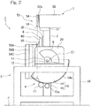
- Fig. 2 is a side view thereof.
- the testing device 1 for the thin-walled large bearing includes a face board 2, a face board support mechanism 3, an angle change drive device 4, a face board fixing mechanism 5, a bearing installation mechanism 6, and a bearing rotating mechanism 7.
- a bearing 60 as a test target to be subjected to a performance evaluation test by the testing device 1 is, for example, the thin-walled large bearing used for supporting a rotating mount 71 such as a gantry of a CT scanner device 70 shown in Fig. 8 .
- the thin-walled large bearing is a rolling bearing such as a deep groove ball bearing, an angular contact ball bearing, a 4-point contact ball bearing, a cylindrical roller bearing, or a tapered roller bearing, for example.
- a rolling bearing such as a deep groove ball bearing, an angular contact ball bearing, a 4-point contact ball bearing, a cylindrical roller bearing, or a tapered roller bearing, for example.
- the face board 2 is used for installing thereon the bearing 60 as the test target, which is the thin-walled large bearing.
- the face board 2 is a ring-like plate body having an octagonal outer shape and having an opening 2a ( Fig. 6 ) at the center thereof.
- the face board support mechanism 3 includes: a frame 10 placed on a floor surface F; and a pair of right and left tilting support bearing mechanisms 11 provided at an upper end of the frame 10, and rotatably supports a pair of tilting central shafts 12 protruding from right and left side surfaces of the face board 2, by the pair of right and left tilting support bearing mechanisms 11, respectively.
- a central axis C1 of the tilting central shaft 12 horizontally extends along the right-left direction, and coincides with a diameter line of the bearing 60 as the test target installed on the face board 2. Instead of coinciding with the diameter line of the bearing 60 as the test target, the central axis C1 of the tilting central shaft 12 may be parallel with the diameter line of the bearing 60 as the test target.
- the face board support mechanism 3 the face board 2 is supported such that the face board 2 can be tilted around the central axis C1 of the tilting central shaft 12.
- the angle change drive device 4 is a device for changing a tilt angle of the face board 2 around the central axis C1 of the tilting central shaft 12.
- the angle change drive device 4 includes a rotation transmission mechanism 16 composed of: a rotated element 14 fixed on one (in the example shown in the drawings, right one) of the right and left side surfaces of the face board 2; and a rotating element 15 provided on the frame 10.
- the angle change drive device 4 tilts the face board 2 together with the rotated element 14 by rotating the rotating element 15 by a rotational drive source 17 such as a motor provided on the frame 10.
- the rotation of the rotational drive source 17 is transmitted to the rotating element 15 via a reduction gear (not shown) such as a worm reduction gear so that the speed of the rotation is reduced.
- the rotated element 14 is formed by attaching a chain 14a in a fixed manner to the outer circumference of a fan-shaped plate material centered on the central axis C1 of the tilting central shaft 12.
- the rotating element 15 is a sprocket having a claw 15a formed on the outer circumference thereof and to be engaged with the chain 14a.
- the rotated element 14 and the rotating element 15 may be gears having teeth engaged with each other.
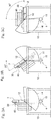
- the orientation of the face board 2 can be changed in a range from a horizontal orientation through a vertical orientation to a tilted orientation by the angle change drive device 4.
- the orientation of the face board 2 can be changed from the tilted orientation (forward tilt at 35 degrees) shown in Fig. 3B to the horizontal orientation (backward tilt at 90 degrees) shown in Fig. 3C .
- the CT scanner device 70 Fig. 8
- the CT scanner device 70 conducts a test while changing the tilt of the rotating mount 71 ( Fig. 8 ) in a range of about ⁇ 30 degrees.
- the face board fixing mechanism 5 is a mechanism for fixing the face board 2 to the face board support mechanism 3, at any tilt angle or a predetermined tilt angle.
- Fig. 4 and Fig. 5 show an example of the face board fixing mechanism 5.
- the face board fixing mechanism 5 shown in Fig. 4 has a fixation plate 20 provided on the frame 10 and having a plurality of arc-shaped guide grooves 20a, 20b, and 20c which are different in their radiuses and concentric about the central axis C1 of the tilting central shaft 12. Screw shafts 21A, 21B, and 21C with their ends screwed into a side surface of the face board 2 are inserted through the respective guide grooves 20a, 20b, and 20c of the fixation plate 20.
- Each screw shaft 21A, 21B, 21C is provided with a contact member 22 formed integrally therewith and having a greater diameter than those of the screw shafts 21A, 21B, 21C.
- a rotational operation lever 23 is attached to the contact member 22. The rotational operation lever 23 is turned to screw the screw shaft 21A (21B, 21C) into the face board 2 and cause the contact member 22 to strongly contact with the fixation plate 20, thereby fixing the face board 2 to the fixation plate 20 by means of a friction force between the contact member 22 and the fixation plate 20.
- the face board 2 is fixed at any tilt angle.
- the screw shafts 21A, 21B, and 21C may be provided in a fixed state to the face board 2, and a nut (not shown) screwed to each screw shaft 21A, 21B, 21C may be fastened to fix the face board 2 to the fixation plate 20 by means of a friction force between the nut and the fixation plate 20.
- a nut (not shown) screwed to each screw shaft 21A, 21B, 21C may be fastened to fix the face board 2 to the fixation plate 20 by means of a friction force between the nut and the fixation plate 20.
- three pairs of the guide grooves 20a, 20b, and 20c and the screw shafts 21A, 21B, and 21C are provided, but the number of the pairs is not limited to three.
- the face board fixing mechanism 5 is provided at each of the right and the left, but may be provided at only one of the right and the left.
- the bearing installation mechanism 6 is a mechanism for installing the bearing 60 as the test target in a state in which the bearing 60 is placed on the face board 2, and includes: a general-purpose frame 30 to which an outer ring 60a ( Fig. 6 ) of the bearing 60 as the test target is fixed; and a frame fixing module 31 for fixing the general-purpose frame 30 to the face board 2.
- the general-purpose frame 30 is a ring-shaped plate material having an opening 30a at the center thereof.
- fixation of the outer ring 60a to the general-purpose frame 30 is made by inserting a bolt 33 into a through hole 61 formed along the axial direction in the outer ring 60a, and then screwing a thread portion of the bolt 33 into a screw hole 34 formed in the general-purpose frame 30.
- a plurality of the through holes 61 and a plurality of the screw holes 34 are provided, along respective concentric circles, in the outer ring 60a and the general-purpose frame 30, respectively.
- a plurality of screw holes 34 are provided along each of a plurality of concentric circles having different diameters.
- a bearing 60 having any outer diameter can be selected from among the bearings 60 as the test targets having plural types of outer diameters, and each of the bearings 60 can be concentrically installed on the one general-purpose frame 30 in an exchangeable manner, i.e., a selective manner.
- Through holes may be formed along the axial direction in the face board 2 and the general-purpose frame 30, and a screw hole (not shown) may be formed in the outer ring 60a, whereby the outer ring 60a may be fastened to be fixed to the general-purpose frame 30 by a bolt (not shown) inserted from the face board 2 side.
- a bolt not shown
- the frame fixing module 31 is composed of: a bolt insertion hole 36 formed along the axial direction in the general-purpose frame 30; a screw hole 37 formed in the face board 2 so as to correspond to the bolt insertion hole 36; and a fixation bolt 38 to be inserted through the bolt insertion hole 36 and screwed into the screw hole 37.
- a fixation bolt 38 is inserted into the bolt insertion hole 36, an adjustment gap 39 is formed therebetween at least in the radial direction.
- the bolt insertion hole 36 is formed to be a circular hole having a greater hole diameter than the diameter of the fixation bolt 38, or a long hole elongated in the radial direction.
- the fixation bolt 38 inserted through the bolt insertion hole 36 is screwed into the screw hole 37 to fix the general-purpose frame 30 to the face board 2, and here, a positioning mechanism 41 ( Fig. 1 ) is provided for causing the center of the general-purpose frame 30 to coincide with a center O of the face board 2 before the fixation bolt 38 is fastened.
- the positioning mechanism 41 is composed of two positioning mechanism portions 41A and 41B provided at two positions separated in the circumferential direction of the face board 2.
- the positions where the positioning mechanism portions 41A and 41B are provided are not particularly limited, but it is preferable that the positions thereof are lower than the tilting central shaft 12 when the face board 2 is tilted.
- the positioning mechanism portions 41A and 41B each have an eccentric contact member 42 which is rotatable around a central axis C2 perpendicular to a general-purpose frame fixation surface 2a of the face board 2.
- a rotation support shaft 43 having upper and lower portions 43a and 43b respectively extending upward and downward from upper and lower end surfaces of the eccentric contact member 42 is rotatably supported by a support member 44 fixed to the face board 2.
- the center of the rotation support shaft 43 coincides with the central axis C2.
- the eccentric contact member 42 has a cylindrical shape and the central axis C2 is eccentric with respect to a center Q of the cylinder.
- the upper portion 43a of the rotation support shaft 43 has an operation hole 45 penetrating in a direction perpendicular to the central axis C2.
- an end side of an upper shaft support portion 44a of the support member 44 is divided via a slit 47 into two parts which become branched pieces 44aa and 44ab.
- a fastening screw 48 is inserted from one branched piece 44aa side, and a thread portion of the fastening screw 48 is screwed into the other branched piece 44ab.
- a lever 49 attached to a base end of the fastening screw 48 By turning a lever 49 attached to a base end of the fastening screw 48, the length by which the fastening screw 48 is screwed into the other branched piece 44ab is changed, whereby each of the branched pieces 44aa and 44ab is elastically deformed and the distance therebetween is changed.
- the distance is shortened, as shown in Fig.
- the bearing rotating mechanism 7 transmits rotation of a bearing rotation motor 52 provided on a bracket 51 fixed to the face board 2, to an inner ring 60b of the bearing 60 as the test target, via a belt transmission device 53.
- the belt transmission device 53 is composed of: a driving pulley 54 attached to an output shaft 52a of the bearing rotation motor 52; a driven pulley 55 fixed to the inner ring 60b of the bearing 60 as the test target; and a belt 56 wound around the driving pulley 54 and the driven pulley 55.
- the driven pulley 55 is provided concentrically with the inner ring 60b, and as shown in Fig.
- the bearing rotating mechanism 7 is capable of rotating the inner ring 60b of the bearing 60 as the test target at a rotation speed of about 400 revolutions per minute.
- a plurality of weights 58A, 58B, and 58C for applying a moment load to the inner ring 60b are attached by bolts 59 in a stacked manner.
- the weight value of each of the weights 58A, 58B, and 58C and the number of the weights to be attached can be freely selected. Since the driven pulley 55 and the weights 58A, 58B, and 58C are located on the same side in the axial direction with respect to the bearing 60 as the test target, the moment load can be effectively applied to the bearing 60 as the test target.
- Sensors (not shown) for detecting respectively torque acting on the bearing 60 as the test target, and vibration, heat, sound, etc. generated during rotation are attached at corresponding appropriate positions in the testing device 1.
- a usage method of the testing device 1 will be described.
- the face board support mechanism 3 and the angle change drive device 4 the face board 2 is set in the horizontal orientation as shown in Fig. 3C .
- the general-purpose frame 30 to which the bearing 60 as the test target has been fixed is installed on the face board 2 set in the horizontal orientation.
- the fixation of the bearing 60 as the test target to the general-purpose frame 30 may be performed at a place separated from the testing device 1.
- the installation of the general-purpose frame 30 on the face board 2 is performed through the following procedure.
- the general-purpose frame 30 to which the bearing 60 as the test target has been fixed is placed roughly at a target installation position on the face board 2, using a crane or the like.
- the fixation bolt 38 is inserted into the bolt insertion hole 36 of the general-purpose frame 30, and the fixation bolt 38 is screwed into the screw hole 37 of the face board 2.
- the fixation bolt 38 is not completely screwed into the screw hole 37. Therefore, the general-purpose frame 30 has not been fixed to the face board 2 yet, and the general-purpose frame 30 can be moved within a range of the adjustment gap 39 between the bolt insertion hole 36 and the fixation bolt 38.
- the positioning mechanism 41 In this state, by the positioning mechanism 41, the general-purpose frame 30 is positioned such that the center of the general-purpose frame 30 coincides with the center O of the face board 2.
- the positioning method is as follows: the eccentric contact member 42 of each of the positioning mechanism portions 41A and 41B is set in a rotation allowed state, and is rotated so that the largest radius portion of the eccentric contact member 42 is directed toward the center O of the face board 2 as shown by a solid line in Fig. 7A . Thereafter, the eccentric contact member 42 is set in a rotation prevented state.
- each of a plurality of portions of an outer circumferential surface of the general-purpose frame 30 contacts with the largest radius portion of the eccentric contact member 42, whereby the center of the general-purpose frame 30 is positioned at a proper position so as to coincide with the center O of the face board 2.
- the general-purpose frame 30 placed at the rough position is positioned farther from the positioning mechanism portions 41A and 41B than the center O of the face board 2 is, since there is a gap between the general-purpose frame 30 and the eccentric contact member 42, the general-purpose frame 30 is shifted on the face board 2 so as to fill the gap, whereby the general-purpose frame 30 is positioned at a proper position.
- the fixation bolt 38 ( Fig. 1 ) is fastened to fix the general-purpose frame 30 to the face board 2.
- the rotation prevented state of the eccentric contact member 42 is cancelled, and the eccentric contact member 42 is rotated to direct the smallest radius portion thereof toward the center O of the face board 2, so that the eccentric contact member 42 does not contact with the general-purpose frame 30.
- wearing of the bearing 60 as the test target due to fretting of the eccentric contact member 42 can be prevented.
- the general-purpose frame 30 is installed on the face board 2 set in the horizontal orientation, it is only necessary to lower the general-purpose frame 30 from above onto the face board 2 in installation of the bearing, and it is not necessary to support the general-purpose frame 30 in a proper orientation by a person. Therefore, even if the bearing 60 as the test target is the thin-walled large bearing with a great weight, the general-purpose frame 30 can be easily installed on the face board 2.
- the general-purpose frame 30 is placed on the face board 2 set in the horizontal orientation, a load from the bearing 60 as the test target and the general-purpose frame 30 is uniformly applied to the face board 2. Therefore, position adjustment of the general-purpose frame 30 along a bearing installation surface 2b of the face board 2 can be easily performed, and the bearing 60 as the test target can be accurately installed at the center of the face board 2.
- the driven pulley 55 and the weights 58A, 58B, and 58C are attached to the inner ring 60b of the bearing 60 as the test target.
- the driven pulley 55 and the weights 58A, 58B, and 58C may be attached to the inner ring 60b of the bearing 60 as the test target before the general-purpose frame 30 is installed on the face board 2.
- the belt 56 is wound around the driving pulley 54 and the driven pulley 55, whereby test preparation is completed.
- the face board 2 is set in the vertical orientation or the tilted orientation, to conduct a performance evaluation test of the bearing 60 as the test target.
- the face board 2 is fixed at a determined tilt angle by the face board fixing mechanism 5.
- the performance evaluation test is conducted by rotating the inner ring 60b of the bearing 60 as the test target by the bearing rotation motor 52 and then reading a value detected by each of the above sensors. Since the face board 2 can be changed at any tilt angle or a predetermined tile angle, the performance evaluation test of the bearing 60 as the test target can be conducted in a state close to the usage state.
- the CT scanner device 70 shown in Fig. 8 will be described.
- the CT scanner device 70 includes: an examination unit 73 having an opening portion 72; and a cradle 74 movable in the opening portion 72.
- the rotating mount 71 on the inner circumferential side is rotatably supported via two bearings 60 as rolling test targets on a fixation portion 75 on the outer circumferential side.
- the rotating mount 71 is provided with an X-ray tube 76 and an X-ray detector 77 located opposite to each other in the diameter direction.
- the cradle 74 on which an examination subject 78 such as a patient is laid is inserted into the opening portion 72 of the examination unit 73, the rotating mount 71 is rotated around the cradle 74 while X-rays are irradiated from the X-ray tube 76, and then the X-rays transmitted through the examination subject are detected by the X-ray detector 77, whereby a sectional image of the examination subject 78 is obtained.
Landscapes
- Health & Medical Sciences (AREA)
- Physics & Mathematics (AREA)
- Life Sciences & Earth Sciences (AREA)
- Engineering & Computer Science (AREA)
- General Physics & Mathematics (AREA)
- Medical Informatics (AREA)
- Pathology (AREA)
- Heart & Thoracic Surgery (AREA)
- High Energy & Nuclear Physics (AREA)
- Theoretical Computer Science (AREA)
- Nuclear Medicine, Radiotherapy & Molecular Imaging (AREA)
- Optics & Photonics (AREA)
- Pulmonology (AREA)
- Radiology & Medical Imaging (AREA)
- Biomedical Technology (AREA)
- Biophysics (AREA)
- Molecular Biology (AREA)
- Surgery (AREA)
- Animal Behavior & Ethology (AREA)
- General Health & Medical Sciences (AREA)
- Public Health (AREA)
- Veterinary Medicine (AREA)
- Acoustics & Sound (AREA)
- Apparatus For Radiation Diagnosis (AREA)
- Testing Of Devices, Machine Parts, Or Other Structures Thereof (AREA)
Abstract
Description
- This application is based on and claims Convention priority to Japanese patent application No.
2013-152397, filed July 23, 2013 - The present invention relates to a testing device for conducting various tests of a thin-walled large bearing used in, for example, a CT scanner device which is a medical examination device.
- A CT scanner device (for example, Fig. 13 in Patent Document 1) has, as an examination unit, a circular rotating mount (gantry) which allows a cradle on which an examination subject such as a patient is laid to enter thereto and exit therefrom. The rotating mount is rotatably supported via a bearing on a fixing unit on the outer circumferential side, and is provided with an X-ray tube, an X-ray detector, and the like for capturing an image. The bearing used for supporting the rotating mount is a thin-walled large bearing with an outer diameter of about 600 to 1300 mm, and a load of about 1 t from mounted components such as the X-ray tube is applied to an inner ring of the bearing. Depending on a part to be imaged, such as an eyeball, the angle of the imaging needs to be changed, and therefore some CT scanner devices are configured such that the tilt angle of the rotating mount can be changed. In such CT scanner devices, the load applied to the bearing varies depending on the tilt angle of the rotating mount.
- Generally, the bearing for supporting the rotating mount of the CT scanner device is required to have the following performances.
- (1) Silence. This prevents an organ from being contracted due to patient's tension, and gives a sense of ease to the patient, to keep the organ acting normally.
- (2) Low vibration. The lower the vibration is, the higher the quality of a captured image is.
- (3) High speed. Shortening a time needed for imaging reduces the X-ray exposed dose.
- In order to assure the above performances of the bearing for supporting the rotating mount, it is necessary to conduct a performance evaluation test before the bearing is incorporated into the CT scanner device. An example of such testing devices is disclosed in
Patent Document 2. This testing device holds the bearing such that the bearing can be tilted at any angle, by a bearing holding mechanism, and allows an inner ring of the held bearing to be rotated at any rotation speed, thus enabling a performance evaluation test of the bearing under various conditions. -
- [Patent Document 1] JP Laid-open Patent Publication No.
2012-82844 - [Patent Document 2]
JP Laid-open Patent Publication No. 2005-315681 -
Patent Document 2 describes that, since the baring can be tilted at any angle, the testing device is capable to make "the attachment orientation of the bearing be the same as that of, for example, a rolling bearing used for supporting a CT scanner gantry head". However, the specification ofPatent Document 2 does not disclose that the bearing can be held horizontally. In addition, since the testing device is such a type that the bearing is fixed by being fitted into a depressed portion of a housing, the bearing can be fixed to the housing even when the bearing is in a vertical orientation. Thus, it is considered that, in this testing device, the bearing is attached to the bearing holding mechanism in a state in which the bearing is set in a vertical orientation or in a tilted orientation. Since the bearing used in the CT scanner device is large and heavy, it is not easy to attach the bearing to the bearing holding mechanism while a person supports the bearing in an appropriate orientation. In addition, when the bearing is in a vertical orientation or in a tilted orientation, a gap between the bearing holding mechanism and the bearing becomes uneven in the circumferential direction due to the influence of the weight of the bearing, and therefore it is difficult to attach the bearing at the center of the bearing holding mechanism. - An object of the present invention is to provide a testing device for a thin-walled large bearing, that allows the thin-walled large bearing as a test target to be easily and accurately installed and allows a performance evaluation test to be conducted with the installed thin-walled large bearing tilted in any orientation.
- A testing device for a thin-walled large bearing of the present invention includes: a face board configured to allow the thin-walled large bearing as a test target to be installed thereon; a face board support mechanism configured to support the face board such that the face board can be tilted around a tilting central shaft set to be horizontal, the tilting central shaft coinciding with or being parallel with a diameter line of the bearing installed on the face board; an angle change drive device configured to change a tilt angle of the face board; and a bearing rotation motor installed on the face board and configured to rotate an inner ring of the bearing. The face board support mechanism and the angle change drive device are capable of changing an orientation of the face board in a range from a horizontal orientation through a vertical orientation to a tilted orientation. The face board is provided with a bearing installation mechanism configured to install the bearing such that the bearing is placed on the face board and an outer ring of the bearing is fixed. The "thin-walled large bearing" as the test target in the present invention refers to a bearing in which a difference between an inner diameter and an outer diameter thereof with respect to the inner diameter is smaller than that of a general bearing, and the inner diameter is great, for example, a bearing in which a value of (outer diameter - inner diameter) / (inner diameter) is 0.3 or smaller and the inner diameter is 600 mm or greater.
- According to the above configuration, the face board is set in the horizontal orientation by the face board support mechanism and the angle change drive device, and the bearing is installed by the bearing installation mechanism in a state in which the bearing is placed on the face board set in the horizontal orientation. Since the face board is horizontal, it is only necessary to lower the bearing set in the horizontal orientation from above onto the face board in installation of the bearing, and it is not necessary to support the bearing in a proper orientation by a person. Therefore, even if the bearing is the thin-walled large bearing, the bearing can be easily installed on the face board. In addition, when the bearing is placed on the face board set in the horizontal orientation, the weight of the bearing is uniformly applied to the face board. Therefore, position adjustment of the bearing along a bearing placement surface of the face board can be easily performed, and the bearing can be accurately installed at the center of the face board. Further, since the installation is performed in a state in which the bearing is placed on the face board, application to bearings having various outer diameters is easy, unlike a method in which a bearing is fitted into a face board.
- After the bearing is installed on the face board, the face board is set in the vertical orientation or the tilted orientation, and the inner ring of the bearing installed on the face board is rotated by the bearing rotation motor, whereby a performance evaluation test of the bearing is conducted. Since the angle of the face board can be changed to any tilt angle or a predetermined tilt angle, the performance evaluation test of the bearing can be conducted in a state close to a usage state.
- In the present invention, the bearing installation mechanism may include: a ring-shaped general-purpose frame which is detachably provided on the face board and is capable of selectively and concentrically fixing each of bearings having plural types of outer diameters; and a frame fixing module configured to fix the general-purpose frame to the face board. In this case, application to plural types of bearings having different outer diameters is enabled with a single bearing installation mechanism. In addition, the bearing can be fixed to the general-purpose frame at a place separated from the testing device, and the general-purpose frame to which the bearing is fixed can be fixed to the face board. Even if the type of the outer diameter of the bearing fixed to the general-purpose frame differs, operation for fixing the general-purpose frame to the face board is the same, and therefore work for installing the bearing on the face board is simplified.
- The frame fixing module may include: a bolt insertion hole formed in the general-purpose frame or the face board; and a fixation bolt to be inserted into the bolt insertion hole so as to form an adjustment gap therebetween, to fix the general-purpose frame to the face board. A positioning mechanism may be provided which is configured to cause a center of the general-purpose frame to coincide with a center of the face board before fastening by the fixation bolt is performed. The positioning mechanism may be composed of: eccentric contact members rotatably provided at an eccentric position around a central axis perpendicular to the face board, to contact with respective plural positions of an outer circumferential surface of the general-purpose frame; and a rotation preventing module configured to switch the eccentric contact member between a rotation prevented state and a rotation allowed state.
- In this case, the general-purpose frame is fixed to the face board through the following procedure. First, the general-purpose frame to which the bearing as the test target is fixed is placed roughly at a target installation position on the face board. At this stage, the general-purpose frame has not been fixed to the face board yet, and the general-purpose frame can be moved within a range of the adjustment gap between the bolt insertion hole and the fixation bolt. In this state, the center of the general-purpose frame is caused to coincide with the center of the face board by the positioning mechanism. Then, the fixation bolt is fastened to fix the general-purpose frame to the face board. The positioning mechanism is composed of plural sets of the eccentric contact member and the rotation preventing module, and is configured to cause the eccentric contact members to contact with the respective plural positions of an outer circumferential surface of the general-purpose frame, thereby positioning the general-purpose frame. Therefore, the mechanism is simple, and the positioning operation is easy.
- In the present invention, a weight may be provided which is detachably attached to the inner ring of the bearing, to generate a moment load to the bearing. By providing the weight, the same moment load as that would be applied to the bearing in a usage state can be applied to the bearing.
- In the present invention, a face board fixing mechanism configured to fix the face board to the face board support mechanism at any tilt angle or a predetermined tilt angle may be provided separately from the angle change drive device. By providing the face board fixing mechanism, the tilt angle of the face board can be prevented with high accuracy from being unintentionally changed during a test or the like.
- Thus, the testing device for the thin-walled large bearing of the present invention is suitable for conducting a performance evaluation test of a bearing for supporting a rotating mount of a CT scanner device.
- Any combination of at least two constructions, disclosed in the appended claims and/or the specification and/or the accompanying drawings should be construed as included within the scope of the present invention. In particular, any combination of two or more of the appended claims should be equally construed as included within the scope of the present invention.
- In any event, the present invention will become more clearly understood from the following description of preferred embodiments thereof, when taken in conjunction with the accompanying drawings. However, the embodiments and the drawings are given only for the purpose of illustration and explanation, and are not to be taken as limiting the scope of the present invention in any way whatsoever, which scope is to be determined by the appended claims. In the accompanying drawings, like reference numerals are used to denote like parts throughout the several views, and:
-
Fig. 1 is a front view of a testing device for a thin-walled large bearing according to an embodiment of the present invention; -
Fig. 2 is a side view of the testing device for the thin-walled large bearing; -
Fig. 3A is a side view schematically showing a state in which a face board of the testing device for the thin-walled large bearing is in a vertical orientation; -
Fig. 3B is a side view schematically showing a state in which the face board of the testing device for the thin-walled large bearing is in a tilted orientation; -
Fig. 3C is a side view schematically showing a state in which the face board of the testing device for the thin-walled large bearing is in a horizontal orientation; -
Fig. 4 is a side view of a face board fixing mechanism of the testing device for the thin-walled large bearing; -
Fig. 5 is a view including a perspective view of the face board fixing mechanism and a partial enlarged view thereof; -
Fig. 6 is a broken side view of a part of the testing device for the thin-walled large bearing; -
Fig. 7A is a plan view of a positioning mechanism of the testing device for the thin-walled large bearing; -
Fig. 7B is a side view of the positioning mechanism of the testing device for the thin-walled large bearing; and -
Fig. 8 is a sectional view of an example of a CT scanner device. - An embodiment of a testing device for a thin-walled large bearing according to the present invention will be described with reference to
Fig. 1 to Fig. 7B .Fig. 1 is a front view of the testing device for the thin-walled large bearing, andFig. 2 is a side view thereof. Thetesting device 1 for the thin-walled large bearing includes aface board 2, a faceboard support mechanism 3, an anglechange drive device 4, a faceboard fixing mechanism 5, abearing installation mechanism 6, and a bearingrotating mechanism 7. A bearing 60 as a test target to be subjected to a performance evaluation test by thetesting device 1 is, for example, the thin-walled large bearing used for supporting arotating mount 71 such as a gantry of aCT scanner device 70 shown inFig. 8 . The thin-walled large bearing is a rolling bearing such as a deep groove ball bearing, an angular contact ball bearing, a 4-point contact ball bearing, a cylindrical roller bearing, or a tapered roller bearing, for example. A specific configuration of theCT scanner device 70 will be described later. - In
Fig. 1 andFig. 2 , theface board 2 is used for installing thereon thebearing 60 as the test target, which is the thin-walled large bearing. In this example, theface board 2 is a ring-like plate body having an octagonal outer shape and having anopening 2a (Fig. 6 ) at the center thereof. The faceboard support mechanism 3 includes: aframe 10 placed on a floor surface F; and a pair of right and left tiltingsupport bearing mechanisms 11 provided at an upper end of theframe 10, and rotatably supports a pair of tiltingcentral shafts 12 protruding from right and left side surfaces of theface board 2, by the pair of right and left tiltingsupport bearing mechanisms 11, respectively. A central axis C1 of the tiltingcentral shaft 12 horizontally extends along the right-left direction, and coincides with a diameter line of thebearing 60 as the test target installed on theface board 2. Instead of coinciding with the diameter line of thebearing 60 as the test target, the central axis C1 of the tiltingcentral shaft 12 may be parallel with the diameter line of thebearing 60 as the test target. By the faceboard support mechanism 3, theface board 2 is supported such that theface board 2 can be tilted around the central axis C1 of the tiltingcentral shaft 12. - The angle
change drive device 4 is a device for changing a tilt angle of theface board 2 around the central axis C1 of the tiltingcentral shaft 12. The anglechange drive device 4 includes arotation transmission mechanism 16 composed of: a rotatedelement 14 fixed on one (in the example shown in the drawings, right one) of the right and left side surfaces of theface board 2; and arotating element 15 provided on theframe 10. The anglechange drive device 4 tilts theface board 2 together with the rotatedelement 14 by rotating therotating element 15 by arotational drive source 17 such as a motor provided on theframe 10. The rotation of therotational drive source 17 is transmitted to therotating element 15 via a reduction gear (not shown) such as a worm reduction gear so that the speed of the rotation is reduced. For example, the rotatedelement 14 is formed by attaching achain 14a in a fixed manner to the outer circumference of a fan-shaped plate material centered on the central axis C1 of the tiltingcentral shaft 12. Therotating element 15 is a sprocket having aclaw 15a formed on the outer circumference thereof and to be engaged with thechain 14a. The rotatedelement 14 and therotating element 15 may be gears having teeth engaged with each other. - As shown in
Fig. 3A to Fig. 3C , the orientation of theface board 2 can be changed in a range from a horizontal orientation through a vertical orientation to a tilted orientation by the anglechange drive device 4. For example, as shown inFig. 3A , using the vertical orientation as a reference, the orientation of theface board 2 can be changed from the tilted orientation (forward tilt at 35 degrees) shown inFig. 3B to the horizontal orientation (backward tilt at 90 degrees) shown inFig. 3C . By the way, the CT scanner device 70 (Fig. 8 ) conducts a test while changing the tilt of the rotating mount 71 (Fig. 8 ) in a range of about ± 30 degrees. - The face
board fixing mechanism 5 is a mechanism for fixing theface board 2 to the faceboard support mechanism 3, at any tilt angle or a predetermined tilt angle.Fig. 4 and Fig. 5 show an example of the faceboard fixing mechanism 5. The faceboard fixing mechanism 5 shown inFig. 4 has afixation plate 20 provided on theframe 10 and having a plurality of arc-shapedguide grooves central shaft 12.Screw shafts face board 2 are inserted through therespective guide grooves fixation plate 20. Eachscrew shaft contact member 22 formed integrally therewith and having a greater diameter than those of thescrew shafts rotational operation lever 23 is attached to thecontact member 22. Therotational operation lever 23 is turned to screw thescrew shaft 21A (21B, 21C) into theface board 2 and cause thecontact member 22 to strongly contact with thefixation plate 20, thereby fixing theface board 2 to thefixation plate 20 by means of a friction force between thecontact member 22 and thefixation plate 20. Thus, theface board 2 is fixed at any tilt angle. - Instead of the above configuration, the
screw shafts face board 2, and a nut (not shown) screwed to eachscrew shaft face board 2 to thefixation plate 20 by means of a friction force between the nut and thefixation plate 20. In the example inFig. 4 and Fig. 5 , three pairs of theguide grooves screw shafts Fig. 4 and Fig. 5 , the faceboard fixing mechanism 5 is provided at each of the right and the left, but may be provided at only one of the right and the left. - The bearing
installation mechanism 6 is a mechanism for installing thebearing 60 as the test target in a state in which thebearing 60 is placed on theface board 2, and includes: a general-purpose frame 30 to which anouter ring 60a (Fig. 6 ) of thebearing 60 as the test target is fixed; and aframe fixing module 31 for fixing the general-purpose frame 30 to theface board 2. In the example inFig. 6 , the general-purpose frame 30 is a ring-shaped plate material having anopening 30a at the center thereof. - As shown in
Fig. 6 , fixation of theouter ring 60a to the general-purpose frame 30 is made by inserting abolt 33 into a throughhole 61 formed along the axial direction in theouter ring 60a, and then screwing a thread portion of thebolt 33 into ascrew hole 34 formed in the general-purpose frame 30. A plurality of the throughholes 61 and a plurality of the screw holes 34 are provided, along respective concentric circles, in theouter ring 60a and the general-purpose frame 30, respectively. In addition, in the general-purpose frame 30, a plurality of screw holes 34 are provided along each of a plurality of concentric circles having different diameters. Therefore, for one general-purpose frame 30, abearing 60 having any outer diameter can be selected from among thebearings 60 as the test targets having plural types of outer diameters, and each of thebearings 60 can be concentrically installed on the one general-purpose frame 30 in an exchangeable manner, i.e., a selective manner. Through holes (not shown) may be formed along the axial direction in theface board 2 and the general-purpose frame 30, and a screw hole (not shown) may be formed in theouter ring 60a, whereby theouter ring 60a may be fastened to be fixed to the general-purpose frame 30 by a bolt (not shown) inserted from theface board 2 side. However, in light of handling performance, attachment performance, and the like, it is desirable that theouter ring 60a is fastened to be fixed to the general-purpose frame 30 by thebolt 33 inserted from theouter ring 60a side, as in the present embodiment. - The
frame fixing module 31 is composed of: abolt insertion hole 36 formed along the axial direction in the general-purpose frame 30; ascrew hole 37 formed in theface board 2 so as to correspond to thebolt insertion hole 36; and afixation bolt 38 to be inserted through thebolt insertion hole 36 and screwed into thescrew hole 37. When thefixation bolt 38 is inserted into thebolt insertion hole 36, anadjustment gap 39 is formed therebetween at least in the radial direction. In order to form theadjustment gap 39, thebolt insertion hole 36 is formed to be a circular hole having a greater hole diameter than the diameter of thefixation bolt 38, or a long hole elongated in the radial direction. - The
fixation bolt 38 inserted through thebolt insertion hole 36 is screwed into thescrew hole 37 to fix the general-purpose frame 30 to theface board 2, and here, a positioning mechanism 41 (Fig. 1 ) is provided for causing the center of the general-purpose frame 30 to coincide with a center O of theface board 2 before thefixation bolt 38 is fastened. Thepositioning mechanism 41 is composed of twopositioning mechanism portions face board 2. The positions where thepositioning mechanism portions central shaft 12 when theface board 2 is tilted. - As shown in
Fig. 7A and Fig. 7B , thepositioning mechanism portions eccentric contact member 42 which is rotatable around a central axis C2 perpendicular to a general-purposeframe fixation surface 2a of theface board 2. Specifically, as shown inFig. 7B , arotation support shaft 43 having upper andlower portions eccentric contact member 42 is rotatably supported by asupport member 44 fixed to theface board 2. The center of therotation support shaft 43 coincides with the central axis C2. Theeccentric contact member 42 has a cylindrical shape and the central axis C2 is eccentric with respect to a center Q of the cylinder. Theupper portion 43a of therotation support shaft 43 has anoperation hole 45 penetrating in a direction perpendicular to the central axis C2. By inserting a tool (not shown) into theoperation hole 45 and turning the tool, theeccentric contact member 42 can be rotated around the central axis C2. - As shown in
Fig. 7A , an end side of an uppershaft support portion 44a of thesupport member 44 is divided via aslit 47 into two parts which become branched pieces 44aa and 44ab. Afastening screw 48 is inserted from one branched piece 44aa side, and a thread portion of thefastening screw 48 is screwed into the other branched piece 44ab. By turning alever 49 attached to a base end of thefastening screw 48, the length by which thefastening screw 48 is screwed into the other branched piece 44ab is changed, whereby each of the branched pieces 44aa and 44ab is elastically deformed and the distance therebetween is changed. When the distance is shortened, as shown inFig. 7B , theupper portion 43a of therotation support shaft 43 is tightened, whereby rotation of theeccentric contact member 42 is prevented. When the distance is increased, the tightening of theupper portion 43a of therotation support shaft 43 is released, whereby theeccentric contact member 42 is allowed to rotate. That is, the branched pieces 44aa and 44ab, thefastening screw 48, and thelever 49 shown inFig. 7A compose arotation preventing module 50 for switching theeccentric contact member 42 between a rotation prevented state and a rotation allowed state. - In
Fig. 1 andFig. 2 , the bearingrotating mechanism 7 transmits rotation of abearing rotation motor 52 provided on abracket 51 fixed to theface board 2, to aninner ring 60b of thebearing 60 as the test target, via abelt transmission device 53. Thebelt transmission device 53 is composed of: a drivingpulley 54 attached to anoutput shaft 52a of thebearing rotation motor 52; a drivenpulley 55 fixed to theinner ring 60b of thebearing 60 as the test target; and abelt 56 wound around the drivingpulley 54 and the drivenpulley 55. The drivenpulley 55 is provided concentrically with theinner ring 60b, and as shown inFig. 6 , is fixed to theinner ring 60b by abolt 57 fastening a large-diameter portion 55b which protrudes toward the outer diameter side relative to abelt wound portion 55a. For example, the bearingrotating mechanism 7 is capable of rotating theinner ring 60b of thebearing 60 as the test target at a rotation speed of about 400 revolutions per minute. - As shown in
Fig. 2 , on a surface of the drivenpulley 55 opposite to a surface thereof that contacts with theinner ring 60b of thebearing 60 as the test target, a plurality ofweights inner ring 60b are attached bybolts 59 in a stacked manner. The weight value of each of theweights pulley 55 and theweights bearing 60 as the test target, the moment load can be effectively applied to thebearing 60 as the test target. Sensors (not shown) for detecting respectively torque acting on thebearing 60 as the test target, and vibration, heat, sound, etc. generated during rotation are attached at corresponding appropriate positions in thetesting device 1. - A usage method of the
testing device 1 will be described. By the faceboard support mechanism 3 and the anglechange drive device 4, theface board 2 is set in the horizontal orientation as shown inFig. 3C . Then, the general-purpose frame 30 to which thebearing 60 as the test target has been fixed is installed on theface board 2 set in the horizontal orientation. The fixation of thebearing 60 as the test target to the general-purpose frame 30 may be performed at a place separated from thetesting device 1. - In detail, the installation of the general-
purpose frame 30 on theface board 2 is performed through the following procedure. First, the general-purpose frame 30 to which thebearing 60 as the test target has been fixed is placed roughly at a target installation position on theface board 2, using a crane or the like. Then, thefixation bolt 38 is inserted into thebolt insertion hole 36 of the general-purpose frame 30, and thefixation bolt 38 is screwed into thescrew hole 37 of theface board 2. At this stage, thefixation bolt 38 is not completely screwed into thescrew hole 37. Therefore, the general-purpose frame 30 has not been fixed to theface board 2 yet, and the general-purpose frame 30 can be moved within a range of theadjustment gap 39 between thebolt insertion hole 36 and thefixation bolt 38. - In this state, by the
positioning mechanism 41, the general-purpose frame 30 is positioned such that the center of the general-purpose frame 30 coincides with the center O of theface board 2. The positioning method is as follows: theeccentric contact member 42 of each of thepositioning mechanism portions eccentric contact member 42 is directed toward the center O of theface board 2 as shown by a solid line inFig. 7A . Thereafter, theeccentric contact member 42 is set in a rotation prevented state. Thus, in the case where the center of the general-purpose frame 30 placed at the rough position is positioned closer to thepositioning mechanism portions face board 2 is, each of a plurality of portions of an outer circumferential surface of the general-purpose frame 30 contacts with the largest radius portion of theeccentric contact member 42, whereby the center of the general-purpose frame 30 is positioned at a proper position so as to coincide with the center O of theface board 2. In the case where the center of the general-purpose frame 30 placed at the rough position is positioned farther from thepositioning mechanism portions face board 2 is, since there is a gap between the general-purpose frame 30 and theeccentric contact member 42, the general-purpose frame 30 is shifted on theface board 2 so as to fill the gap, whereby the general-purpose frame 30 is positioned at a proper position. After the positioning is finished, the fixation bolt 38 (Fig. 1 ) is fastened to fix the general-purpose frame 30 to theface board 2. - After the general-
purpose frame 30 is fixed to theface board 2, the rotation prevented state of theeccentric contact member 42 is cancelled, and theeccentric contact member 42 is rotated to direct the smallest radius portion thereof toward the center O of theface board 2, so that theeccentric contact member 42 does not contact with the general-purpose frame 30. Thus, during a test, wearing of thebearing 60 as the test target due to fretting of theeccentric contact member 42 can be prevented. - Thus, in the case where the general-
purpose frame 30 is installed on theface board 2 set in the horizontal orientation, it is only necessary to lower the general-purpose frame 30 from above onto theface board 2 in installation of the bearing, and it is not necessary to support the general-purpose frame 30 in a proper orientation by a person. Therefore, even if thebearing 60 as the test target is the thin-walled large bearing with a great weight, the general-purpose frame 30 can be easily installed on theface board 2. When the general-purpose frame 30 is placed on theface board 2 set in the horizontal orientation, a load from the bearing 60 as the test target and the general-purpose frame 30 is uniformly applied to theface board 2. Therefore, position adjustment of the general-purpose frame 30 along a bearing installation surface 2b of theface board 2 can be easily performed, and thebearing 60 as the test target can be accurately installed at the center of theface board 2. - After the general-
purpose frame 30 is installed on theface board 2, the drivenpulley 55 and theweights inner ring 60b of thebearing 60 as the test target. The drivenpulley 55 and theweights inner ring 60b of thebearing 60 as the test target before the general-purpose frame 30 is installed on theface board 2. Finally, thebelt 56 is wound around the drivingpulley 54 and the drivenpulley 55, whereby test preparation is completed. - After the test preparation is completed, the
face board 2 is set in the vertical orientation or the tilted orientation, to conduct a performance evaluation test of thebearing 60 as the test target. At this time, theface board 2 is fixed at a determined tilt angle by the faceboard fixing mechanism 5. Thereby, the tilt angle of theface board 2 can be reliably prevented from being unintentionally changed during a test or the like, thus ensuring security. The performance evaluation test is conducted by rotating theinner ring 60b of thebearing 60 as the test target by thebearing rotation motor 52 and then reading a value detected by each of the above sensors. Since theface board 2 can be changed at any tilt angle or a predetermined tile angle, the performance evaluation test of thebearing 60 as the test target can be conducted in a state close to the usage state. - The
CT scanner device 70 shown inFig. 8 will be described. TheCT scanner device 70 includes: anexamination unit 73 having an openingportion 72; and acradle 74 movable in the openingportion 72. In theexamination unit 73, therotating mount 71 on the inner circumferential side is rotatably supported via twobearings 60 as rolling test targets on afixation portion 75 on the outer circumferential side. Therotating mount 71 is provided with anX-ray tube 76 and anX-ray detector 77 located opposite to each other in the diameter direction. Thecradle 74 on which an examination subject 78 such as a patient is laid is inserted into the openingportion 72 of theexamination unit 73, therotating mount 71 is rotated around thecradle 74 while X-rays are irradiated from theX-ray tube 76, and then the X-rays transmitted through the examination subject are detected by theX-ray detector 77, whereby a sectional image of the examination subject 78 is obtained. - Although the present invention has been fully described in connection with the preferred embodiments thereof with reference to the accompanying drawings which are used only for the purpose of illustration, those skilled in the art will readily conceive numerous changes and modifications within the framework of obviousness upon the reading of the specification herein presented of the present invention. Accordingly, such changes and modifications are, unless they depart from the scope of the present invention as delivered from the claims annexed hereto, to be construed as included therein.
-
- 1 ····testing device
- 2 ····face board
- 3 ····face board support mechanism
- 4 ····angle change drive device
- 5 ····face board fixing mechanism
- 6 ····bearing installation mechanism
- 7 ····bearing rotating mechanism
- 12 ····tilting central shaft
- 30 ····general-purpose frame
- 31 ····frame fixing module
- 41 ····positioning mechanism
- 42 ....eccentric contact member
- 50 ····rotation preventing module
- 52 ····bearing rotation motor
- 58A, 58B, 58C ····weight
- 60 ····bearing as test target
- 70 ····CT scanner device
- 71 ····rotating mount
- C1 ····central axis of tilting central shaft
- C2 ····central axis perpendicular to face board
- O ····center of face board
Claims (6)
- A testing device for a thin-walled large bearing, comprising:a face board configured to allow the thin-walled large bearing as a test target to be installed thereon;a face board support mechanism configured to support the face board such that the face board can be tilted around a tilting central shaft set to be horizontal, the tilting central shaft coinciding with or being parallel with a diameter line of the bearing installed on the face board;an angle change drive device configured to change a tilt angle of the face board; anda bearing rotation motor installed on the face board and configured to rotate an inner ring of the bearing, whereinthe face board support mechanism and the angle change drive device are capable of changing an orientation of the face board in a range from a horizontal orientation through a vertical orientation to a tilted orientation, andthe face board is provided with a bearing installation mechanism configured to install the bearing such that the bearing is placed on the face board and an outer ring of the bearing is fixed.
- The testing device for the thin-walled large bearing, as claimed in claim 1, wherein
the bearing installation mechanism includes: a ring-shaped general-purpose frame which is detachably provided on the face board and is capable of selectively and concentrically fixing each of bearings having plural types of outer diameters; and a frame fixing module configured to fix the general-purpose frame to the face board. - The testing device for the thin-walled large bearing, as claimed in claim 2, wherein
the frame fixing module includes: a bolt insertion hole formed in the general-purpose frame or the face board; and a fixation bolt to be inserted into the bolt insertion hole so as to form an adjustment gap therebetween, to fix the general-purpose frame to the face board,
a positioning mechanism is provided which is configured to cause a center of the general-purpose frame to coincide with a center of the face board before fastening by the fixation bolt is performed, and
the positioning mechanism is composed of: a plurality of eccentric contact members rotatably provided at an eccentric position around a central axis perpendicular to the face board, to contact with respective plural positions of an outer circumferential surface of the general-purpose frame; and a rotation preventing module configured to switch the eccentric contact member between a rotation prevented state and a rotation allowed state. - The testing device for the thin-walled large bearing, as claimed in any one of claims 1 to 3, wherein
a weight is provided which is detachably attached to the inner ring of the bearing, to generate a moment load to the bearing. - The testing device for the thin-walled large bearing, as claimed in any one of claims 1 to 4, wherein
a face board fixing mechanism configured to fix the face board to the face board support mechanism at any tilt angle or a predetermined tilt angle is provided separately from the angle change drive device. - The testing device for the thin-walled large bearing, as claimed in any one of claims 1 to 5, wherein
the bearing is a bearing to support a rotating mount of a CT scanner device.
Applications Claiming Priority (2)
| Application Number | Priority Date | Filing Date | Title |
|---|---|---|---|
| JP2013152397A JP6173815B2 (en) | 2013-07-23 | 2013-07-23 | Thin large bearing test equipment |
| PCT/JP2014/068673 WO2015012139A1 (en) | 2013-07-23 | 2014-07-14 | Testing device for thin-walled large bearing |
Publications (2)
| Publication Number | Publication Date |
|---|---|
| EP3026414A1 true EP3026414A1 (en) | 2016-06-01 |
| EP3026414A4 EP3026414A4 (en) | 2017-03-01 |
Family
ID=52393183
Family Applications (1)
| Application Number | Title | Priority Date | Filing Date |
|---|---|---|---|
| EP14830127.8A Withdrawn EP3026414A4 (en) | 2013-07-23 | 2014-07-14 | Testing device for thin-walled large bearing |
Country Status (6)
| Country | Link |
|---|---|
| US (1) | US20160139000A1 (en) |
| EP (1) | EP3026414A4 (en) |
| JP (1) | JP6173815B2 (en) |
| KR (1) | KR20160034314A (en) |
| CN (1) | CN105408732A (en) |
| WO (1) | WO2015012139A1 (en) |
Cited By (1)
| Publication number | Priority date | Publication date | Assignee | Title |
|---|---|---|---|---|
| DE102024203962A1 (en) * | 2024-04-29 | 2025-10-30 | Siemens Healthineers Ag | Method for checking a rotary bearing of a gantry of a computed tomography system |
Families Citing this family (15)
| Publication number | Priority date | Publication date | Assignee | Title |
|---|---|---|---|---|
| JP6297373B2 (en) * | 2014-03-22 | 2018-03-20 | Ntn株式会社 | Thin large bearing test equipment |
| CN106596107B (en) * | 2016-12-27 | 2019-03-26 | 华南理工大学 | A kind of flexible precision thin-wall bearing fault diagnosis life testing machine |
| CN106769045B (en) * | 2017-01-06 | 2019-05-31 | 洛阳轴承研究所有限公司 | A kind of RV retarder base bearing performance testing device |
| CN106769050B (en) * | 2017-02-16 | 2023-06-16 | 通用技术集团昆明机床股份有限公司 | Measuring device for measuring rigidity of bearing group of machine tool spindle |
| CN108692940B (en) * | 2018-06-12 | 2023-11-24 | 华南理工大学 | A transmission shaft assembly for sequential testing of flexible thin-walled bearings |
| DE102018132582A1 (en) * | 2018-12-18 | 2020-06-18 | Schaeffler Technologies AG & Co. KG | Test bench and method for testing a bearing |
| CN109443216B (en) * | 2018-12-27 | 2023-11-28 | 上海机动车检测认证技术研究中心有限公司 | Part positioning device for scanning test |
| WO2020250857A1 (en) * | 2019-06-12 | 2020-12-17 | 株式会社ジェイテクト | Rolling bearing test device, and method for testing rolling bearing |
| CN111474321B (en) * | 2020-05-20 | 2022-06-28 | 山东理工职业学院 | A vehicle axle detection device and detection method |
| CN112362345A (en) * | 2020-10-19 | 2021-02-12 | 徐正涛 | Test fixture for testing rotation fluency of bearings with different sizes |
| CN114184380B (en) * | 2021-11-26 | 2024-08-02 | 人本股份有限公司 | CT machine turntable bearing test device |
| CN115389203A (en) * | 2022-09-20 | 2022-11-25 | 洛阳Lyc轴承有限公司 | Testing device for main bearing of high-speed CT machine |
| KR102696341B1 (en) * | 2023-05-02 | 2024-08-19 | 한국생산기술연구원 | Fixing and load-applying device for testing wave generator bearings and performance test method of wave generator bearings using the device |
| KR102610065B1 (en) * | 2023-08-17 | 2023-12-05 | 한화시스템(주) | Rotator for concentricity measurement and runout adjustment |
| CN117091841B (en) * | 2023-10-09 | 2023-12-26 | 山西阳光三极科技股份有限公司 | Bearing detection device of railway wagon |
Family Cites Families (11)
| Publication number | Priority date | Publication date | Assignee | Title |
|---|---|---|---|---|
| JPS59190207U (en) * | 1983-06-06 | 1984-12-17 | 株式会社島津製作所 | computer tomography device |
| JP4092563B2 (en) * | 2002-12-19 | 2008-05-28 | 日本精工株式会社 | Resonance measuring device and resonance measuring method of bearing device |
| JP2005315681A (en) * | 2004-04-28 | 2005-11-10 | Nsk Ltd | Bearing test equipment |
| JP4311290B2 (en) * | 2004-07-12 | 2009-08-12 | 日本精工株式会社 | Stationary wheel creep test apparatus and test method for rolling bearings |
| JP4942496B2 (en) * | 2007-01-26 | 2012-05-30 | Ntn株式会社 | Bearing state inspection device and bearing state inspection method |
| CN100593702C (en) * | 2008-09-01 | 2010-03-10 | 洛阳工铭机电设备有限公司 | Helicopter automatic tilting device large-sized thin-wall bearing intelligent checking analytical method and device |
| JP2010091091A (en) * | 2008-10-10 | 2010-04-22 | Ntn Corp | Cage for rolling bearing, and rolling bearing for ct scanner |
| CN201575909U (en) * | 2009-11-27 | 2010-09-08 | 洛阳工铭机电设备有限公司 | Detecting device for ceramic ball bearing with heavy caliber and thin wall |
| JP2012082844A (en) | 2010-10-06 | 2012-04-26 | Ntn Corp | Rolling bearing |
| CN102809487B (en) * | 2012-08-09 | 2014-12-03 | 浙江传媒学院 | Mute life testing machine of rolling bearing |
| JP6297373B2 (en) * | 2014-03-22 | 2018-03-20 | Ntn株式会社 | Thin large bearing test equipment |
-
2013
- 2013-07-23 JP JP2013152397A patent/JP6173815B2/en not_active Expired - Fee Related
-
2014
- 2014-07-14 EP EP14830127.8A patent/EP3026414A4/en not_active Withdrawn
- 2014-07-14 WO PCT/JP2014/068673 patent/WO2015012139A1/en not_active Ceased
- 2014-07-14 CN CN201480041335.6A patent/CN105408732A/en active Pending
- 2014-07-14 KR KR1020167002097A patent/KR20160034314A/en not_active Withdrawn
-
2016
- 2016-01-20 US US15/001,870 patent/US20160139000A1/en not_active Abandoned
Non-Patent Citations (1)
| Title |
|---|
| See references of WO2015012139A1 * |
Cited By (2)
| Publication number | Priority date | Publication date | Assignee | Title |
|---|---|---|---|---|
| DE102024203962A1 (en) * | 2024-04-29 | 2025-10-30 | Siemens Healthineers Ag | Method for checking a rotary bearing of a gantry of a computed tomography system |
| DE102024203962B4 (en) * | 2024-04-29 | 2025-11-06 | Siemens Healthineers Ag | Method for checking a rotary bearing of a gantry of a computed tomography system |
Also Published As
| Publication number | Publication date |
|---|---|
| JP2015021921A (en) | 2015-02-02 |
| WO2015012139A1 (en) | 2015-01-29 |
| EP3026414A4 (en) | 2017-03-01 |
| KR20160034314A (en) | 2016-03-29 |
| JP6173815B2 (en) | 2017-08-02 |
| US20160139000A1 (en) | 2016-05-19 |
| CN105408732A (en) | 2016-03-16 |
Similar Documents
| Publication | Publication Date | Title |
|---|---|---|
| EP3026414A1 (en) | Testing device for thin-walled large bearing | |
| EP3124949A1 (en) | Testing device for thin-walled large-sized bearing | |
| US7419450B2 (en) | Light source apparatus for electronic endoscope and electronic endoscope having the light source apparatus | |
| US20020168044A1 (en) | Tiltable gantry for X-ray tomography system | |
| JPH1057368A (en) | X-ray computed tomography apparatus | |
| EP1762177A2 (en) | X-ray computed tomographic apparatus | |
| JP4431523B2 (en) | X-ray irradiation apparatus and X-ray imaging apparatus | |
| JP2016023996A (en) | Vibration measuring device | |
| US7217038B2 (en) | Fixing structure for rolling bearing | |
| KR101855581B1 (en) | An apparatus for inserting a needle | |
| KR101651565B1 (en) | Target apparatus of x-ray generator | |
| JPWO2022113416A5 (en) | ||
| JP4761898B2 (en) | X-ray computed tomography system | |
| KR101651564B1 (en) | Target apparatus capable of shielding x-ray | |
| US20240407740A1 (en) | Integrated computed tomography rotating base with an integrated drive system | |
| US20250366800A1 (en) | Integrated stationary and rotating computed tomography gantry structure with a unified drive | |
| US20250241604A1 (en) | Head image acquisition device and head image acquisition method | |
| JP2007130119A (en) | X-ray CT system | |
| JP4694316B2 (en) | Light source device for electronic endoscope and electronic endoscope device | |
| EP4105508A1 (en) | Rotation mechanism for x-ray examination device, x-ray examination device, and adjustment method for rotation mechanism for x-ray examination device | |
| US9074987B2 (en) | Lubricant distribution acquisition device and lubricant distribution acquisition method | |
| KR20140096912A (en) | A rotating support assembly and a photographing apparatus comprising the same | |
| KR20160056573A (en) | Dental x-ray imaging apparatus having gantry housing |
Legal Events
| Date | Code | Title | Description |
|---|---|---|---|
| PUAI | Public reference made under article 153(3) epc to a published international application that has entered the european phase |
Free format text: ORIGINAL CODE: 0009012 |
|
| 17P | Request for examination filed |
Effective date: 20160201 |
|
| AK | Designated contracting states |
Kind code of ref document: A1 Designated state(s): AL AT BE BG CH CY CZ DE DK EE ES FI FR GB GR HR HU IE IS IT LI LT LU LV MC MK MT NL NO PL PT RO RS SE SI SK SM TR |
|
| AX | Request for extension of the european patent |
Extension state: BA ME |
|
| DAX | Request for extension of the european patent (deleted) | ||
| A4 | Supplementary search report drawn up and despatched |
Effective date: 20170201 |
|
| RIC1 | Information provided on ipc code assigned before grant |
Ipc: A61B 6/03 20060101ALI20170126BHEP Ipc: G01M 13/04 20060101AFI20170126BHEP |
|
| 17Q | First examination report despatched |
Effective date: 20171121 |
|
| STAA | Information on the status of an ep patent application or granted ep patent |
Free format text: STATUS: THE APPLICATION HAS BEEN WITHDRAWN |
|
| 18W | Application withdrawn |
Effective date: 20180320 |