EP3026257A1 - Schaufel für Wasserturbine - Google Patents
Schaufel für Wasserturbine Download PDFInfo
- Publication number
- EP3026257A1 EP3026257A1 EP14290359.0A EP14290359A EP3026257A1 EP 3026257 A1 EP3026257 A1 EP 3026257A1 EP 14290359 A EP14290359 A EP 14290359A EP 3026257 A1 EP3026257 A1 EP 3026257A1
- Authority
- EP
- European Patent Office
- Prior art keywords
- vane
- plates
- inner element
- hydraulic
- stay
- Prior art date
- Legal status (The legal status is an assumption and is not a legal conclusion. Google has not performed a legal analysis and makes no representation as to the accuracy of the status listed.)
- Granted
Links
Images

Classifications
-
- F—MECHANICAL ENGINEERING; LIGHTING; HEATING; WEAPONS; BLASTING
- F03—MACHINES OR ENGINES FOR LIQUIDS; WIND, SPRING, OR WEIGHT MOTORS; PRODUCING MECHANICAL POWER OR A REACTIVE PROPULSIVE THRUST, NOT OTHERWISE PROVIDED FOR
- F03B—MACHINES OR ENGINES FOR LIQUIDS
- F03B3/00—Machines or engines of reaction type; Parts or details peculiar thereto
- F03B3/12—Blades; Blade-carrying rotors
- F03B3/121—Blades, their form or construction
-
- F—MECHANICAL ENGINEERING; LIGHTING; HEATING; WEAPONS; BLASTING
- F05—INDEXING SCHEMES RELATING TO ENGINES OR PUMPS IN VARIOUS SUBCLASSES OF CLASSES F01-F04
- F05B—INDEXING SCHEME RELATING TO WIND, SPRING, WEIGHT, INERTIA OR LIKE MOTORS, TO MACHINES OR ENGINES FOR LIQUIDS COVERED BY SUBCLASSES F03B, F03D AND F03G
- F05B2240/00—Components
- F05B2240/20—Rotors
- F05B2240/30—Characteristics of rotor blades, i.e. of any element transforming dynamic fluid energy to or from rotational energy and being attached to a rotor
- F05B2240/301—Cross-section characteristics
-
- F—MECHANICAL ENGINEERING; LIGHTING; HEATING; WEAPONS; BLASTING
- F05—INDEXING SCHEMES RELATING TO ENGINES OR PUMPS IN VARIOUS SUBCLASSES OF CLASSES F01-F04
- F05B—INDEXING SCHEME RELATING TO WIND, SPRING, WEIGHT, INERTIA OR LIKE MOTORS, TO MACHINES OR ENGINES FOR LIQUIDS COVERED BY SUBCLASSES F03B, F03D AND F03G
- F05B2240/00—Components
- F05B2240/20—Rotors
- F05B2240/30—Characteristics of rotor blades, i.e. of any element transforming dynamic fluid energy to or from rotational energy and being attached to a rotor
- F05B2240/302—Segmented or sectional blades
-
- F—MECHANICAL ENGINEERING; LIGHTING; HEATING; WEAPONS; BLASTING
- F05—INDEXING SCHEMES RELATING TO ENGINES OR PUMPS IN VARIOUS SUBCLASSES OF CLASSES F01-F04
- F05B—INDEXING SCHEME RELATING TO WIND, SPRING, WEIGHT, INERTIA OR LIKE MOTORS, TO MACHINES OR ENGINES FOR LIQUIDS COVERED BY SUBCLASSES F03B, F03D AND F03G
- F05B2260/00—Function
- F05B2260/30—Retaining components in desired mutual position
- F05B2260/301—Retaining bolts or nuts
-
- Y—GENERAL TAGGING OF NEW TECHNOLOGICAL DEVELOPMENTS; GENERAL TAGGING OF CROSS-SECTIONAL TECHNOLOGIES SPANNING OVER SEVERAL SECTIONS OF THE IPC; TECHNICAL SUBJECTS COVERED BY FORMER USPC CROSS-REFERENCE ART COLLECTIONS [XRACs] AND DIGESTS
- Y02—TECHNOLOGIES OR APPLICATIONS FOR MITIGATION OR ADAPTATION AGAINST CLIMATE CHANGE
- Y02E—REDUCTION OF GREENHOUSE GAS [GHG] EMISSIONS, RELATED TO ENERGY GENERATION, TRANSMISSION OR DISTRIBUTION
- Y02E10/00—Energy generation through renewable energy sources
- Y02E10/20—Hydro energy
Definitions
- the present invention generally relates to hydraulic turbines. More in particular, the present invention relates to guide vanes and stay vanes for a hydraulic turbine.
- stay vanes and guide vanes are one of the main parts of hydraulic turbines such as, for example, Francis, Kaplan or pump turbine.
- Stay vanes are main components of stay rings, which are normally constructed of upper and lower ring plates to which stay vanes are attached, normally welded. Stay vanes are fixed and not adjustable once welded. They have streamline shape to produce minimum losses in flow. The number of stay vanes, per stay ring, usually varies from 15 to 24. Inside hydraulic turbine, stay rings and stay vanes have several important functions: erection, hydraulic, structural and sealing function.
- the main erection function of stay rings is to ensure leveling between a head cover and a bottom ring during turbine erection.
- the main hydraulic functions of the stay rings are: to guide the water flow to get the required velocity field in inlet of hydraulic regulation devices (guide vanes), to minimize hydraulic head losses, and to prevent Karman fluctuation at the outlet of stay vane trailing edge.
- Important structural function of stay rings is to sustain the different load cases, including concreting, normal operating cases, and exceptional operating cases.
- their sealing function is to ensure sealing between inlet and distributor (i.e. stay ring-head cover and stay ring-bottom ring).
- Guide vanes of Kaplan, Francis or pump turbines are hydraulic parts positioned around a runner of the turbine. There are normally from 20 to 24 guide vanes per turbine. The guide vanes control the runner inlet flow by being rotated due to operating mechanical system. Similarly to stay vanes, guide vanes are also of a streamline shape. The guide vanes have to be designed to perform several important functions.
- the guide vanes have to control the leakage flow in a closed position.
- the guide vanes seal the distributor by obstruction.
- the obstruction is not perfect and there are three leaking areas: two functional clearances between the hydraulic profile sides and the wearing plates (upper and lower), and the contact between two guide vanes.
- the guide vanes design should prevent any break of the guide vanes in an accidental jamming case. At closure, a foreign body can jam between two guide vanes.
- a safety device ensures that the reaction of operating load will not break the guide vane body.
- hydraulic shape of the guide vanes has to be sustainable and long lasting. The hydraulic shape can be damaged by its environment. Beside the corrosion phenomena the water flow carries solid foreign bodies which impact and scratch the hydraulic parts.
- the design has to facilitate the hydraulic shape maintenance. Considering that the turbine owner wants to rework the hydraulic shape because it has been damaged, the state of the art design obliges him to dismantle the head cover and to take back the involved guide vane. This involves a huge time waste and production loss.
- the object of the present invention is to solve the aforementioned problems by providing a hydraulic turbine vane as substantially defined in independent claim 1.
- the present solution discloses a vane for a hydraulic turbine, comprising at least two plates consecutively disposed such to form a hollow hydraulic shape, and an inner element at least partially enclosed by said at least two plates, and wherein at least one of the plates is removably attached to the inner element.
- all the plates are removably attached to the inner element.
- At least two plates are removably attached to each other.
- the number of plates is four or five.
- plates are attached to the inner element and/or to each other using removable assembly technology, such as bolts.
- the inner element is rectangular shaped beam or plate, preferably made of carbon steel.
- At least one of the plates is made of a composite material, preferably glass fiber reinforced composite.
- the vane further comprises at least one clearance between at least one plate and the inner element.
- the vane comprises at least two clearances separated by the inner element.
- the clearance between the plates and the inner element is at least partially filled with a foam material.
- the vane is a stay vane for hydraulic turbine.
- the vane further comprises an upper trunnion or/and a lower trunnion.
- the vane further comprises an upper side cover and/or a bottom side cover at least partially attached to the vane.
- the vane is a guide vane for hydraulic turbine.
- the current application also provides for stay ring and hydraulic turbine comprising at least one of the vanes described above.
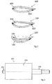
- stay vanes 100 With reference to figure 1 , it is showed three variations of stay vanes 100 from the prior art.
- the hydraulic profiles, all of streamlined shape, are slightly different, but all of them are constructed by welding two plates 102 and 104.
- stay vanes usually have a hollow profile, and they are made of steel. Before welding, the plates are often rolled or folded with machine tool. That is why the design is a manufacturable two dimensional (2D) section.
- stay vanes could have a full profile, instead of hollow profile, manufactured by a casting.
- Figure 2 shows a perspective view of a guide vane 200 from the prior art.
- guide vanes are made of a steel material, and they have three main parts: hydraulic profile 204, a lower trunnion 202, and an upper trunnion 206.
- Figure 3a shows a cross section of a stay vane 300 according to an embodiment of the present invention.
- the vane 300 comprises two plates 301 and 302 consecutively disposed forming a hydraulic shape.
- the plates may have different shapes such as straight, curved, and rounded.
- the plates may also have different thicknesses. In general number of plates is at least two.
- An inner element 306 is enclosed by the plates 301 and 302.
- one plate 301 is removably attached to the inner element 306.
- the at least two plates 301 and 302 can be removably attached to each other.
- removably attached in general it is meant, for example, that the plate 301 can be dismantled from the inner element 306 and mounted again.
- One example of the means to removably attach the plates to the inner element 306 is using bolts.
- the plate 302 is also removably attached to the inner element 306.
- Figure 3b shows a cross section of a vane 300 according to preferred embodiment of the present invention.
- the vane 300 comprises 4 plates 301, 302, 303, and 304 consecutively disposed forming a hydraulic shape.
- An inner element 306 is enclosed by the plates 301, 302, 303, and 304.
- all plates 301, 302, 303, and 304 are removably attached to the inner element 306.
- the at least two consecutive plates such as 301 and 303 can be removably attached to each other.
- the inner element 306 is a painted carbon steel or stainless steel plate or beam with a simple geometry section, such as rectangular. In general, the inner element 306 contributes to the structural function.
- At least one of the plates 301, 302, 303, and 304 is made of a composite material, preferably glass fiber reinforced composite. In one preferred embodiment of the present invention, all the plates 301,302,303 and 304 are made of a composite material.
- the composite shaping processes make possible to manufacture easily three dimensional (3D) hydraulic profiles.
- 3D composite plates can improve the water flow quality in turbine, concerning the assumption of velocity field uniformity in the vertical dimension; 3D composite plates allow the hydraulic profile to go paste the rings on the radial direction of the distributor, and ensure hydraulic continuity with the water guides.
- the dismountable composite plates allow modifying the hydraulic shape with a minimum machine down-time.
- the lightweight plates facilitate the handling. This particular advantage of the vane 300 according to the invention can be used for a hydraulic optimization or in case of machine refurbishment.
- Composite material advantages makes possible to sustain the profile shape and surface finishes against water and solid impacts during operation. An improvement of environmental resistance is expected comparing with the painted carbon steel solution.
- the plates of the vane 300 according to the invention are dismountable to make possible to commute a worn one. The worn plates can be repaired in workshop.
- the composite solution allows trailing edges of the vane 300 thin design up to zero thickness. This allows better to optimize the shape of the profile of the vane 300 against Karman phenomenon.
- the clearance 310 there is a clearance 310 between the plates 301 and 302 and the inner element.
- at least part of the clearance 307, 308, 309, 310, or whole clearance can advantageously be filled with a foam material.
- the foam material is used to improve the strength of the plates during operating conditions (against pressure load) and in an accidental case (impact of a foreign body).
- the foam material contributes to structural function.
- the example of the foam material that can be used is polyurethane.
- the vane 300 according to the invention may be advantageously used as a stay vane of a hydraulic turbine.
- Figure 4 shows a perspective view of a stay vane 300 mounted on a part of a lower ring 404 of a stay ring according to an embodiment of the present invention.
- Figure 4 is sketched to show only upper parts of the plates, so that an inner structure of the vane 300 including the foam 320 and the inner element 306 is visible.
- the inner element 306 is attached or welded to the lower ring 404.
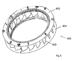
- Figure 5 shows a perspective view of a stay ring 400 according to an embodiment of the present invention.
- the main elements of the stay ring 400 are an upper ring 402, the lower ring 404 and a plurality of stay vanes 300.
- the inner element is attached to the upper ring 402 and the lower ring 404, in one embodiment the attachment is by welding.
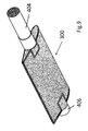
- Figure 6 shows a cross section view of a vane according to another embodiment of the present invention.
- the inner element 306 is following the shape of the adjacent plates 302 and 304, so that there can be substantially no clearance between plates 301 and 302 and the inner element 306.
- the plates 304 and 305 are removably attached to each other. In this embodiment they are attached using bolts.
- a clearance 309 between the plates 304,305 and the inner element 306, and a clearance 310 between the plate 303 and the inner element 306, are in this embodiment filled with a foam material.
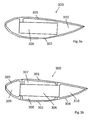
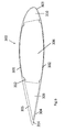
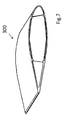
- the perspective view of this embodiment according to the invention is shown in Figure 7 .
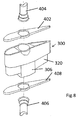
- this design of the vane 300 may be advantageously used for a guide vane of a hydraulic turbine as shown in Figure 8 and Figure 9 .
- the guide vane 300 comprises an upper trunnion 404, a lower trunnion 406, an upper side cover 402 and a bottom side cover 408, the both covers may be attached to the hydraulic shape of the vane 300.
- the upper trunnion 404, the inner element 306 and the lower trunnion 406 may be attached one to each other or may be created out of a single piece, preferably of steel material.
- Figure 8 is sketched to show only upper parts of the plates, so that an inner structure of the vane 300 including the foam 320 and the inner element 306 is visible.
- the plates of the vane 300 and the side covers 402,408 are composed of structural glass fiber reinforced composite material. Such a composite material may be shaped by an infusion molding or RTM light processes.
- the foams 320 may casted on the leading and trailing edges of the vane 300.
- the plates are joined on the inner element 306 by bolting solutions.
- Figure 9 shows the guide vane assembled of the parts shown in Figure 8 .
- the proposed design of the guide vane 300 has many advantages comparing to prior art solutions.
- the proposed design makes possible to include flexible membranes in the hydraulic shape sides. By pressurizing the chamber inside the hydraulic profile, it is possible to induce enough deformations in the membranes to reduce clearances on the sides and avoid leakage.
- the new design uses the flexible property of composite to ensure a superior contact area, so that the sealing is controlled on the contact line leading edge/ trailing edge.
- the composite shaping processes permit to insert elongation gauge in part body, and to monitor the structure and adapt the self-resetting system to detect an unusual elongation on the panel critical areas.
- the composite plates protect effectively vanes against impacts and scratches.
- the new design includes composite plates holding on the inner element by a dismountable assembly, so that they can be removed through the distributor without dismantling the head cover.
Landscapes
- Engineering & Computer Science (AREA)
- Chemical & Material Sciences (AREA)
- Combustion & Propulsion (AREA)
- Mechanical Engineering (AREA)
- General Engineering & Computer Science (AREA)
- Hydraulic Turbines (AREA)
Priority Applications (1)
| Application Number | Priority Date | Filing Date | Title |
|---|---|---|---|
| EP14290359.0A EP3026257B1 (de) | 2014-11-28 | 2014-11-28 | Schaufel für Wasserturbine |
Applications Claiming Priority (1)
| Application Number | Priority Date | Filing Date | Title |
|---|---|---|---|
| EP14290359.0A EP3026257B1 (de) | 2014-11-28 | 2014-11-28 | Schaufel für Wasserturbine |
Publications (2)
| Publication Number | Publication Date |
|---|---|
| EP3026257A1 true EP3026257A1 (de) | 2016-06-01 |
| EP3026257B1 EP3026257B1 (de) | 2019-04-17 |
Family
ID=52338933
Family Applications (1)
| Application Number | Title | Priority Date | Filing Date |
|---|---|---|---|
| EP14290359.0A Not-in-force EP3026257B1 (de) | 2014-11-28 | 2014-11-28 | Schaufel für Wasserturbine |
Country Status (1)
| Country | Link |
|---|---|
| EP (1) | EP3026257B1 (de) |
Cited By (2)
| Publication number | Priority date | Publication date | Assignee | Title |
|---|---|---|---|---|
| CN109014649A (zh) * | 2018-08-29 | 2018-12-18 | 哈尔滨电机厂有限责任公司 | 进出水边无焊接坡口结构的固定导叶及装焊工艺方法 |
| GB2589307A (en) * | 2019-10-31 | 2021-06-02 | Nova Innovation Ltd | Tidal turbine blades |
Citations (2)
| Publication number | Priority date | Publication date | Assignee | Title |
|---|---|---|---|---|
| US20060120869A1 (en) * | 2003-03-12 | 2006-06-08 | Wilson Jack W | Cooled turbine spar shell blade construction |
| US20140227100A1 (en) * | 2011-09-23 | 2014-08-14 | Howden Solyvent-Ventect | Rotating Machine Blade with Reinforced Modular Structure |
-
2014
- 2014-11-28 EP EP14290359.0A patent/EP3026257B1/de not_active Not-in-force
Patent Citations (2)
| Publication number | Priority date | Publication date | Assignee | Title |
|---|---|---|---|---|
| US20060120869A1 (en) * | 2003-03-12 | 2006-06-08 | Wilson Jack W | Cooled turbine spar shell blade construction |
| US20140227100A1 (en) * | 2011-09-23 | 2014-08-14 | Howden Solyvent-Ventect | Rotating Machine Blade with Reinforced Modular Structure |
Cited By (3)
| Publication number | Priority date | Publication date | Assignee | Title |
|---|---|---|---|---|
| CN109014649A (zh) * | 2018-08-29 | 2018-12-18 | 哈尔滨电机厂有限责任公司 | 进出水边无焊接坡口结构的固定导叶及装焊工艺方法 |
| GB2589307A (en) * | 2019-10-31 | 2021-06-02 | Nova Innovation Ltd | Tidal turbine blades |
| GB2589307B (en) * | 2019-10-31 | 2023-04-26 | Nova Innovation Ltd | Tidal turbine blades |
Also Published As
| Publication number | Publication date |
|---|---|
| EP3026257B1 (de) | 2019-04-17 |
Similar Documents
| Publication | Publication Date | Title |
|---|---|---|
| CN108560596B (zh) | 可逆式沉管隧道最终接头及其对接施工方法 | |
| CA2921439C (en) | Composite compressor blade for an axial-flow turbomachine | |
| US8777160B2 (en) | Aircraft including an internal partition | |
| KR101994249B1 (ko) | 풍력발전 타워의 보강 및 증고를 위한 구조 보강체 및 시공방법 | |
| EP3026257B1 (de) | Schaufel für Wasserturbine | |
| US20170088245A1 (en) | Method of manufacturing a rotor body of a magnus-type rotor | |
| CN103953017A (zh) | 龙宫竖管旋流通道切向喷射推水动力轮发电厂 | |
| CN101108648B (zh) | 一种船舶整流导管的制造方法 | |
| US10190565B2 (en) | Method of refurbishing an energy conversion facility and refurbished energy conversion facility | |
| CN103938638A (zh) | 一种深水单壁钢围堰浮筒法的施工方法 | |
| CN110303265A (zh) | 一种低温储罐内罐顶板施工工艺及低温储罐施工工艺 | |
| Kozinec | Generalization of the methodology of studying the durability of segmental gates | |
| CN106969252A (zh) | 正多边形稀油密封气柜改建的单段式橡胶膜密封气柜 | |
| WO2019024290A1 (zh) | 一种双曲面线型舱室脚手架装置搭设方法 | |
| JP6055706B2 (ja) | 渦巻きポンプ | |
| CN106013784A (zh) | 一种角钢框架模板及施工方法 | |
| CN210799000U (zh) | 一种自锚式无支撑杆件的盾构隧道加固体系 | |
| CN110593911B (zh) | 自锚式无支撑杆件的盾构隧道加固体系及其施工方法 | |
| CN205444121U (zh) | 能不断水维修渡槽墙身的临时围护设施 | |
| CN109967975A (zh) | 大型浮式检修门的建造方法 | |
| US1762121A (en) | Hydraulic machine | |
| CN104846850B (zh) | 潮差区和水位变动区的钢板桩防护系统及其施工方法 | |
| CN207452955U (zh) | 一种组合测量塔系统 | |
| US1818050A (en) | Valve construction | |
| CN111946358B (zh) | 一种处置富水砂层中盾尾变形的矫正工装及其施工工艺 |
Legal Events
| Date | Code | Title | Description |
|---|---|---|---|
| PUAI | Public reference made under article 153(3) epc to a published international application that has entered the european phase |
Free format text: ORIGINAL CODE: 0009012 |
|
| AK | Designated contracting states |
Kind code of ref document: A1 Designated state(s): AL AT BE BG CH CY CZ DE DK EE ES FI FR GB GR HR HU IE IS IT LI LT LU LV MC MK MT NL NO PL PT RO RS SE SI SK SM TR |
|
| AX | Request for extension of the european patent |
Extension state: BA ME |
|
| STAA | Information on the status of an ep patent application or granted ep patent |
Free format text: STATUS: REQUEST FOR EXAMINATION WAS MADE |
|
| 17P | Request for examination filed |
Effective date: 20161201 |
|
| RBV | Designated contracting states (corrected) |
Designated state(s): AL AT BE BG CH CY CZ DE DK EE ES FI FR GB GR HR HU IE IS IT LI LT LU LV MC MK MT NL NO PL PT RO RS SE SI SK SM TR |
|
| RAP1 | Party data changed (applicant data changed or rights of an application transferred) |
Owner name: GE RENEWABLE TECHNOLOGIES |
|
| GRAP | Despatch of communication of intention to grant a patent |
Free format text: ORIGINAL CODE: EPIDOSNIGR1 |
|
| STAA | Information on the status of an ep patent application or granted ep patent |
Free format text: STATUS: GRANT OF PATENT IS INTENDED |
|
| INTG | Intention to grant announced |
Effective date: 20181108 |
|
| GRAS | Grant fee paid |
Free format text: ORIGINAL CODE: EPIDOSNIGR3 |
|
| GRAA | (expected) grant |
Free format text: ORIGINAL CODE: 0009210 |
|
| STAA | Information on the status of an ep patent application or granted ep patent |
Free format text: STATUS: THE PATENT HAS BEEN GRANTED |
|
| AK | Designated contracting states |
Kind code of ref document: B1 Designated state(s): AL AT BE BG CH CY CZ DE DK EE ES FI FR GB GR HR HU IE IS IT LI LT LU LV MC MK MT NL NO PL PT RO RS SE SI SK SM TR |
|
| REG | Reference to a national code |
Ref country code: GB Ref legal event code: FG4D |
|
| REG | Reference to a national code |
Ref country code: CH Ref legal event code: EP |
|
| REG | Reference to a national code |
Ref country code: DE Ref legal event code: R096 Ref document number: 602014044838 Country of ref document: DE |
|
| REG | Reference to a national code |
Ref country code: AT Ref legal event code: REF Ref document number: 1121826 Country of ref document: AT Kind code of ref document: T Effective date: 20190515 Ref country code: IE Ref legal event code: FG4D |
|
| REG | Reference to a national code |
Ref country code: NL Ref legal event code: MP Effective date: 20190417 |
|
| REG | Reference to a national code |
Ref country code: LT Ref legal event code: MG4D |
|
| PG25 | Lapsed in a contracting state [announced via postgrant information from national office to epo] |
Ref country code: NL Free format text: LAPSE BECAUSE OF FAILURE TO SUBMIT A TRANSLATION OF THE DESCRIPTION OR TO PAY THE FEE WITHIN THE PRESCRIBED TIME-LIMIT Effective date: 20190417 |
|
| PG25 | Lapsed in a contracting state [announced via postgrant information from national office to epo] |
Ref country code: PT Free format text: LAPSE BECAUSE OF FAILURE TO SUBMIT A TRANSLATION OF THE DESCRIPTION OR TO PAY THE FEE WITHIN THE PRESCRIBED TIME-LIMIT Effective date: 20190817 Ref country code: AL Free format text: LAPSE BECAUSE OF FAILURE TO SUBMIT A TRANSLATION OF THE DESCRIPTION OR TO PAY THE FEE WITHIN THE PRESCRIBED TIME-LIMIT Effective date: 20190417 Ref country code: SE Free format text: LAPSE BECAUSE OF FAILURE TO SUBMIT A TRANSLATION OF THE DESCRIPTION OR TO PAY THE FEE WITHIN THE PRESCRIBED TIME-LIMIT Effective date: 20190417 Ref country code: HR Free format text: LAPSE BECAUSE OF FAILURE TO SUBMIT A TRANSLATION OF THE DESCRIPTION OR TO PAY THE FEE WITHIN THE PRESCRIBED TIME-LIMIT Effective date: 20190417 Ref country code: ES Free format text: LAPSE BECAUSE OF FAILURE TO SUBMIT A TRANSLATION OF THE DESCRIPTION OR TO PAY THE FEE WITHIN THE PRESCRIBED TIME-LIMIT Effective date: 20190417 Ref country code: LT Free format text: LAPSE BECAUSE OF FAILURE TO SUBMIT A TRANSLATION OF THE DESCRIPTION OR TO PAY THE FEE WITHIN THE PRESCRIBED TIME-LIMIT Effective date: 20190417 Ref country code: FI Free format text: LAPSE BECAUSE OF FAILURE TO SUBMIT A TRANSLATION OF THE DESCRIPTION OR TO PAY THE FEE WITHIN THE PRESCRIBED TIME-LIMIT Effective date: 20190417 Ref country code: NO Free format text: LAPSE BECAUSE OF FAILURE TO SUBMIT A TRANSLATION OF THE DESCRIPTION OR TO PAY THE FEE WITHIN THE PRESCRIBED TIME-LIMIT Effective date: 20190717 |
|
| PG25 | Lapsed in a contracting state [announced via postgrant information from national office to epo] |
Ref country code: PL Free format text: LAPSE BECAUSE OF FAILURE TO SUBMIT A TRANSLATION OF THE DESCRIPTION OR TO PAY THE FEE WITHIN THE PRESCRIBED TIME-LIMIT Effective date: 20190417 Ref country code: RS Free format text: LAPSE BECAUSE OF FAILURE TO SUBMIT A TRANSLATION OF THE DESCRIPTION OR TO PAY THE FEE WITHIN THE PRESCRIBED TIME-LIMIT Effective date: 20190417 Ref country code: GR Free format text: LAPSE BECAUSE OF FAILURE TO SUBMIT A TRANSLATION OF THE DESCRIPTION OR TO PAY THE FEE WITHIN THE PRESCRIBED TIME-LIMIT Effective date: 20190718 Ref country code: LV Free format text: LAPSE BECAUSE OF FAILURE TO SUBMIT A TRANSLATION OF THE DESCRIPTION OR TO PAY THE FEE WITHIN THE PRESCRIBED TIME-LIMIT Effective date: 20190417 Ref country code: BG Free format text: LAPSE BECAUSE OF FAILURE TO SUBMIT A TRANSLATION OF THE DESCRIPTION OR TO PAY THE FEE WITHIN THE PRESCRIBED TIME-LIMIT Effective date: 20190717 |
|
| REG | Reference to a national code |
Ref country code: AT Ref legal event code: MK05 Ref document number: 1121826 Country of ref document: AT Kind code of ref document: T Effective date: 20190417 |
|
| PG25 | Lapsed in a contracting state [announced via postgrant information from national office to epo] |
Ref country code: IS Free format text: LAPSE BECAUSE OF FAILURE TO SUBMIT A TRANSLATION OF THE DESCRIPTION OR TO PAY THE FEE WITHIN THE PRESCRIBED TIME-LIMIT Effective date: 20190817 |
|
| REG | Reference to a national code |
Ref country code: DE Ref legal event code: R097 Ref document number: 602014044838 Country of ref document: DE |
|
| PG25 | Lapsed in a contracting state [announced via postgrant information from national office to epo] |
Ref country code: DK Free format text: LAPSE BECAUSE OF FAILURE TO SUBMIT A TRANSLATION OF THE DESCRIPTION OR TO PAY THE FEE WITHIN THE PRESCRIBED TIME-LIMIT Effective date: 20190417 Ref country code: RO Free format text: LAPSE BECAUSE OF FAILURE TO SUBMIT A TRANSLATION OF THE DESCRIPTION OR TO PAY THE FEE WITHIN THE PRESCRIBED TIME-LIMIT Effective date: 20190417 Ref country code: SK Free format text: LAPSE BECAUSE OF FAILURE TO SUBMIT A TRANSLATION OF THE DESCRIPTION OR TO PAY THE FEE WITHIN THE PRESCRIBED TIME-LIMIT Effective date: 20190417 Ref country code: CZ Free format text: LAPSE BECAUSE OF FAILURE TO SUBMIT A TRANSLATION OF THE DESCRIPTION OR TO PAY THE FEE WITHIN THE PRESCRIBED TIME-LIMIT Effective date: 20190417 Ref country code: AT Free format text: LAPSE BECAUSE OF FAILURE TO SUBMIT A TRANSLATION OF THE DESCRIPTION OR TO PAY THE FEE WITHIN THE PRESCRIBED TIME-LIMIT Effective date: 20190417 Ref country code: EE Free format text: LAPSE BECAUSE OF FAILURE TO SUBMIT A TRANSLATION OF THE DESCRIPTION OR TO PAY THE FEE WITHIN THE PRESCRIBED TIME-LIMIT Effective date: 20190417 |
|
| PLBE | No opposition filed within time limit |
Free format text: ORIGINAL CODE: 0009261 |
|
| STAA | Information on the status of an ep patent application or granted ep patent |
Free format text: STATUS: NO OPPOSITION FILED WITHIN TIME LIMIT |
|
| PG25 | Lapsed in a contracting state [announced via postgrant information from national office to epo] |
Ref country code: IT Free format text: LAPSE BECAUSE OF FAILURE TO SUBMIT A TRANSLATION OF THE DESCRIPTION OR TO PAY THE FEE WITHIN THE PRESCRIBED TIME-LIMIT Effective date: 20190417 Ref country code: SM Free format text: LAPSE BECAUSE OF FAILURE TO SUBMIT A TRANSLATION OF THE DESCRIPTION OR TO PAY THE FEE WITHIN THE PRESCRIBED TIME-LIMIT Effective date: 20190417 |
|
| 26N | No opposition filed |
Effective date: 20200120 |
|
| PG25 | Lapsed in a contracting state [announced via postgrant information from national office to epo] |
Ref country code: TR Free format text: LAPSE BECAUSE OF FAILURE TO SUBMIT A TRANSLATION OF THE DESCRIPTION OR TO PAY THE FEE WITHIN THE PRESCRIBED TIME-LIMIT Effective date: 20190417 |
|
| PG25 | Lapsed in a contracting state [announced via postgrant information from national office to epo] |
Ref country code: SI Free format text: LAPSE BECAUSE OF FAILURE TO SUBMIT A TRANSLATION OF THE DESCRIPTION OR TO PAY THE FEE WITHIN THE PRESCRIBED TIME-LIMIT Effective date: 20190417 |
|
| REG | Reference to a national code |
Ref country code: DE Ref legal event code: R119 Ref document number: 602014044838 Country of ref document: DE |
|
| REG | Reference to a national code |
Ref country code: CH Ref legal event code: PL |
|
| PG25 | Lapsed in a contracting state [announced via postgrant information from national office to epo] |
Ref country code: LI Free format text: LAPSE BECAUSE OF NON-PAYMENT OF DUE FEES Effective date: 20191130 Ref country code: CH Free format text: LAPSE BECAUSE OF NON-PAYMENT OF DUE FEES Effective date: 20191130 Ref country code: MC Free format text: LAPSE BECAUSE OF FAILURE TO SUBMIT A TRANSLATION OF THE DESCRIPTION OR TO PAY THE FEE WITHIN THE PRESCRIBED TIME-LIMIT Effective date: 20190417 Ref country code: LU Free format text: LAPSE BECAUSE OF NON-PAYMENT OF DUE FEES Effective date: 20191128 |
|
| REG | Reference to a national code |
Ref country code: BE Ref legal event code: MM Effective date: 20191130 |
|
| GBPC | Gb: european patent ceased through non-payment of renewal fee |
Effective date: 20191128 |
|
| PG25 | Lapsed in a contracting state [announced via postgrant information from national office to epo] |
Ref country code: GB Free format text: LAPSE BECAUSE OF NON-PAYMENT OF DUE FEES Effective date: 20191128 Ref country code: DE Free format text: LAPSE BECAUSE OF NON-PAYMENT OF DUE FEES Effective date: 20200603 Ref country code: FR Free format text: LAPSE BECAUSE OF NON-PAYMENT OF DUE FEES Effective date: 20191130 Ref country code: IE Free format text: LAPSE BECAUSE OF NON-PAYMENT OF DUE FEES Effective date: 20191128 |
|
| PG25 | Lapsed in a contracting state [announced via postgrant information from national office to epo] |
Ref country code: BE Free format text: LAPSE BECAUSE OF NON-PAYMENT OF DUE FEES Effective date: 20191130 |
|
| PG25 | Lapsed in a contracting state [announced via postgrant information from national office to epo] |
Ref country code: CY Free format text: LAPSE BECAUSE OF FAILURE TO SUBMIT A TRANSLATION OF THE DESCRIPTION OR TO PAY THE FEE WITHIN THE PRESCRIBED TIME-LIMIT Effective date: 20190417 |
|
| PG25 | Lapsed in a contracting state [announced via postgrant information from national office to epo] |
Ref country code: HU Free format text: LAPSE BECAUSE OF FAILURE TO SUBMIT A TRANSLATION OF THE DESCRIPTION OR TO PAY THE FEE WITHIN THE PRESCRIBED TIME-LIMIT; INVALID AB INITIO Effective date: 20141128 Ref country code: MT Free format text: LAPSE BECAUSE OF FAILURE TO SUBMIT A TRANSLATION OF THE DESCRIPTION OR TO PAY THE FEE WITHIN THE PRESCRIBED TIME-LIMIT Effective date: 20190417 |
|
| PG25 | Lapsed in a contracting state [announced via postgrant information from national office to epo] |
Ref country code: MK Free format text: LAPSE BECAUSE OF FAILURE TO SUBMIT A TRANSLATION OF THE DESCRIPTION OR TO PAY THE FEE WITHIN THE PRESCRIBED TIME-LIMIT Effective date: 20190417 |