EP3025970A1 - Device for bundling product stacks - Google Patents
Device for bundling product stacks Download PDFInfo
- Publication number
- EP3025970A1 EP3025970A1 EP15195222.3A EP15195222A EP3025970A1 EP 3025970 A1 EP3025970 A1 EP 3025970A1 EP 15195222 A EP15195222 A EP 15195222A EP 3025970 A1 EP3025970 A1 EP 3025970A1
- Authority
- EP
- European Patent Office
- Prior art keywords
- product
- product stack
- conveying direction
- conveyor support
- strapping
- Prior art date
- Legal status (The legal status is an assumption and is not a legal conclusion. Google has not performed a legal analysis and makes no representation as to the accuracy of the status listed.)
- Granted
Links
- 238000000034 method Methods 0.000 claims description 11
- 230000000284 resting effect Effects 0.000 claims description 2
- 239000000047 product Substances 0.000 description 148
- 238000011161 development Methods 0.000 description 12
- 230000018109 developmental process Effects 0.000 description 12
- 230000033001 locomotion Effects 0.000 description 7
- 238000006073 displacement reaction Methods 0.000 description 5
- 230000001133 acceleration Effects 0.000 description 3
- 230000027455 binding Effects 0.000 description 3
- 238000009739 binding Methods 0.000 description 3
- 239000013589 supplement Substances 0.000 description 3
- 239000000969 carrier Substances 0.000 description 2
- 238000005086 pumping Methods 0.000 description 2
- 230000001360 synchronised effect Effects 0.000 description 2
- 240000003517 Elaeocarpus dentatus Species 0.000 description 1
- 230000001419 dependent effect Effects 0.000 description 1
- 239000013013 elastic material Substances 0.000 description 1
- 229920001971 elastomer Polymers 0.000 description 1
- 239000000806 elastomer Substances 0.000 description 1
- 238000005516 engineering process Methods 0.000 description 1
- 239000004744 fabric Substances 0.000 description 1
- 239000000835 fiber Substances 0.000 description 1
- 238000004519 manufacturing process Methods 0.000 description 1
- 239000000463 material Substances 0.000 description 1
- 239000002184 metal Substances 0.000 description 1
- 239000004753 textile Substances 0.000 description 1
Images


Classifications
-
- B—PERFORMING OPERATIONS; TRANSPORTING
- B65—CONVEYING; PACKING; STORING; HANDLING THIN OR FILAMENTARY MATERIAL
- B65B—MACHINES, APPARATUS OR DEVICES FOR, OR METHODS OF, PACKAGING ARTICLES OR MATERIALS; UNPACKING
- B65B13/00—Bundling articles
- B65B13/18—Details of, or auxiliary devices used in, bundling machines or bundling tools
- B65B13/183—Load orienting means
-
- B—PERFORMING OPERATIONS; TRANSPORTING
- B65—CONVEYING; PACKING; STORING; HANDLING THIN OR FILAMENTARY MATERIAL
- B65B—MACHINES, APPARATUS OR DEVICES FOR, OR METHODS OF, PACKAGING ARTICLES OR MATERIALS; UNPACKING
- B65B13/00—Bundling articles
- B65B13/02—Applying and securing binding material around articles or groups of articles, e.g. using strings, wires, strips, bands or tapes
-
- B—PERFORMING OPERATIONS; TRANSPORTING
- B65—CONVEYING; PACKING; STORING; HANDLING THIN OR FILAMENTARY MATERIAL
- B65B—MACHINES, APPARATUS OR DEVICES FOR, OR METHODS OF, PACKAGING ARTICLES OR MATERIALS; UNPACKING
- B65B27/00—Bundling particular articles presenting special problems using string, wire, or narrow tape or band; Baling fibrous material, e.g. peat, not otherwise provided for
- B65B27/08—Bundling paper sheets, envelopes, bags, newspapers, or other thin flat articles
-
- B—PERFORMING OPERATIONS; TRANSPORTING
- B65—CONVEYING; PACKING; STORING; HANDLING THIN OR FILAMENTARY MATERIAL
- B65B—MACHINES, APPARATUS OR DEVICES FOR, OR METHODS OF, PACKAGING ARTICLES OR MATERIALS; UNPACKING
- B65B35/00—Supplying, feeding, arranging or orientating articles to be packaged
- B65B35/10—Feeding, e.g. conveying, single articles
- B65B35/24—Feeding, e.g. conveying, single articles by endless belts or chains
- B65B35/243—Feeding, e.g. conveying, single articles by endless belts or chains using cooperating conveyors engaging the articles simultaneously
-
- B—PERFORMING OPERATIONS; TRANSPORTING
- B65—CONVEYING; PACKING; STORING; HANDLING THIN OR FILAMENTARY MATERIAL
- B65B—MACHINES, APPARATUS OR DEVICES FOR, OR METHODS OF, PACKAGING ARTICLES OR MATERIALS; UNPACKING
- B65B35/00—Supplying, feeding, arranging or orientating articles to be packaged
- B65B35/30—Arranging and feeding articles in groups
- B65B35/40—Arranging and feeding articles in groups by reciprocating or oscillatory pushers
- B65B35/405—Arranging and feeding articles in groups by reciprocating or oscillatory pushers linked to endless conveyors
-
- B—PERFORMING OPERATIONS; TRANSPORTING
- B65—CONVEYING; PACKING; STORING; HANDLING THIN OR FILAMENTARY MATERIAL
- B65G—TRANSPORT OR STORAGE DEVICES, e.g. CONVEYORS FOR LOADING OR TIPPING, SHOP CONVEYOR SYSTEMS OR PNEUMATIC TUBE CONVEYORS
- B65G15/00—Conveyors having endless load-conveying surfaces, i.e. belts and like continuous members, to which tractive effort is transmitted by means other than endless driving elements of similar configuration
- B65G15/10—Conveyors having endless load-conveying surfaces, i.e. belts and like continuous members, to which tractive effort is transmitted by means other than endless driving elements of similar configuration comprising two or more co-operating endless surfaces with parallel longitudinal axes, or a multiplicity of parallel elements, e.g. ropes defining an endless surface
- B65G15/12—Conveyors having endless load-conveying surfaces, i.e. belts and like continuous members, to which tractive effort is transmitted by means other than endless driving elements of similar configuration comprising two or more co-operating endless surfaces with parallel longitudinal axes, or a multiplicity of parallel elements, e.g. ropes defining an endless surface with two or more endless belts
Definitions
- the invention is in the field of conveyor technology and relates to an apparatus and a method for strapping product stacks, the apparatus comprising a first conveyor support and, in the conveying direction of the first conveyor support and spaced from the second conveyor support, wherein between the first and second conveyor support and substantially transversely to the conveying direction a strapping gap for strapping the product stack is formed with a strapping band.
- Sheet-like products such as printed products
- the strapping ensures the cohesion of the product stack.
- product stack can be supplied to a strapping device.
- the product stacks are conveyed for example on a conveyor belt into a strapping position in the strapping device. During this process, it must be ensured that the products which form the product stack do not slip each other and the product stack breaks down.
- the publications DE 102 03 903 A1 and DE 199 20 531 A1 describe in each case a device with a stacker and a subsequent thereto Strapping device for strapping a stack of goods.
- the stack is created by means of the cross stacker and conveyed via a conveyor support in a Umreifungsposition.
- the stack is here on lateral guide and transport walls formed in the manner of an endless conveyor belt and provided with feed tabs, guided laterally.
- the feed tabs run in the conveying direction behind the stack and push the stack against a retractable into the pump room package stop.
- the package stopper is formed by stop bars, which are stationary during operation. During the advancing movement of the not yet strapped stack of goods is guided and supported to the side by the side guide walls and to the rear through the feed tabs. Towards the front in the conveying direction of the stack is supported only in the strapping position by the stationary package stop.
- the stacks come with their leading stack side so only with reaching the Umreifungsposition in abutment with the package stop. During their promotion to the Umreifungsposition the stacks remain in the conveying direction forward but unguided.
- the invention is therefore based on the object to propose a device for strapping product stacks, which allows optimal guidance of the product stack conveyed into the strapping position to each side.
- the product stack should be guided safely in particular at each delivery time. Furthermore, it should be ensured that the stability of the product stack is ensured at any time during acceleration and deceleration of the unbound product stack.
- the invention is characterized by the fact that viewed in the conveying direction on both sides of the second conveyor support each side guide means is arranged, which guide the product stack laterally and enclose a delivery chamber with the second conveyor support.
- the side guide devices form, in particular, a delivery channel with the second delivery support.
- the lateral guiding devices furthermore each contain at least one circumferentially drivable feed limiting element, which protrudes laterally into the conveying space or conveying channel and is designed to make a contact closure with the product stack in order to prevent slippage or slipping of products or product units out of the product stack.
- contact closure in this patent application is quite generally a physical contact, such as frictional contact or stop to understand.
- the two side guide devices for the second conveyor support can be driven by a common or separate drives.
- the feed limiting element is designed in particular to act on the lateral and / or front stack side in a front section of the product stack.
- the feed limiting element is a feed limit stop which, viewed in the conveying direction in the conveying direction, can be moved forwardly relative to the product stack.
- the feed limiting element is a friction element which is designed to produce a frictional contact with the stack side in the conveying direction.
- the lateral stack side is the side guide device facing stack side.
- the two side guide devices are therefore opposite each other, with the second conveyor support disposed therebetween.
- the feed limiting elements of the two side guide devices are in particular aligned with each other by the conveying space or conveying channel moves.
- the two side guide devices are driven in particular synchronously to each other.
- the feed limiting element serves to guide the product stack in the conveying direction against the front when it is stopped when reaching the strapping position.
- the product stack is formed in particular by at least two superimposed product units.
- the product units contain in particular at least one printed product, such as newspaper, magazine, brochure or prospectus.
- the product units may also contain a plurality of nested products.
- the product units may also contain inserts, such as product samples, data carriers or advertising inserts.
- the product units can in particular also be envelopes with inserted advertising supplements.
- the first and second conveying pads are serial along the conveying direction, i. arranged one after the other.
- the strapping gap formed between the first and second conveying supports is in particular part of a strapping space within which the strapping of the product stack takes place.
- the strapping space lies in particular in a plane oriented vertically and transversely to the conveying direction of the product stack.
- the strapping space may be limited by a band guide channel.
- the strapping of the product stack takes place in particular transversely to the conveying direction of the product stack.
- the strapping band with which the product stack is strapped can be made of plastic or metal.
- the strapping can also be a textile structure such as fabric or cord of plastic or natural fibers.
- the lateral guiding devices each contain at least one guide body which is driven circumferentially by at least two deflecting elements spaced apart from one another.
- the guide body is particularly flexible.
- the deflecting elements are arranged in particular perpendicular to the conveyor support.
- the at least one feed limiting element is in this case arranged in particular on the guide body and is rotatable with this.
- the second conveyor support is driven in particular via a drive.
- the second conveyor support is formed by a circumferentially driven conveyor belt, in particular a belt conveyor.
- the second conveyor support is in particular aligned horizontally.
- the conveyor support or the conveyor belt can be integrated in a work table of the device.
- the feed limiting element serves to guide and support the front stacking area in the conveying direction or the front stacking side, in particular during braking of the product stack upon reaching the strapping position.
- a lateral guide device is likewise arranged on both sides of the first conveyor support.
- the two side guide devices guide the product stack laterally. They form together with the conveyor support a pumping room.
- the delivery chamber is in particular a delivery channel.
- these contain at least one circumferentially drivable feed limiting element, which protrudes laterally into the conveying space or conveying channel and is designed to make a contact closure with the product stack in order to prevent slippage of individual products or product units from the product stack in the conveying direction.
- the feed limiting element is a feed limit stop, which is movable in advance in the conveying space in the conveying direction relative to the product stack.
- the feed limiting element is a friction element, which is designed to be connected to the side in the conveying direction, i. to make a frictional contact with the stack side facing this side guide device.
- the two side guide devices are therefore opposite each other, with the second conveyor support disposed therebetween.
- the two side guide devices for the first conveyor pad can be driven by a common or separate drives.
- the feed limiting elements of the two side guide devices are in particular aligned with each other by the conveying space or conveying channel moves.
- the two side guide devices are driven in particular synchronously to each other.
- the two pairings of side guide devices for the first and second conveyor support are in particular driven synchronously with each other.
- the feed limiting element also serves to guide and support the front stacking area in the conveying direction or the front stacking side before the product stack is conveyed with its front stacking side over the strapping gap and into the area of influence of the second conveyor support.
- the feed limiting element ensures that products or product units of the product stack can not slip forward.
- the lateral guiding device for the first conveyor support contains at least one circumferentially drivable feed stop, which in the conveying space or conveying channel in the conveying direction is trailing relative to the product stack.
- the product stack is supported via the feed stop, especially when accelerating the product stack, viewed in the conveying direction towards the rear.
- the product stack can also be pushed over the feed stop in the conveying direction, in particular pushed into the strapping.
- the feed stops of the two side guide devices are in particular aligned with each other by the conveying space or conveying channel moves.
- the two side guide devices with the feed stops are driven in particular synchronously to each other.
- the side guide devices for the first conveyor support each contain both at least one leading feed limiting element and at least one trailing feed stop. As a result, the product stack viewed in the conveying direction is guided both towards the two sides and against the front and against the back and supported against slipping.
- the lateral guiding devices for the first conveying support each comprise at least one guide body, which is driven circumferentially by at least two deflecting members spaced apart from one another.
- the guide body is particularly flexible.
- the deflecting elements are arranged in particular perpendicular to the conveyor support.
- At least one feed limiting element is provided, then this is in particular arranged on the guide body and can be moved circumferentially with it.
- At least one feed stop provided, this is in particular arranged on the guide body and with this circumferentially movable.
- both at least one feed limiting element and at least one feed stop are provided, then these are arranged on a common or on different guide body and with this circumferentially movable.
- the second conveyor support is driven in particular via a drive.
- the first and second conveyor supports can be driven via separate or via a common drive.
- the two conveyor supports are driven in particular synchronously.
- the first conveyor support is formed by a circumferentially driven conveyor belt, in particular a belt conveyor.
- the first conveyor support is in particular aligned horizontally.
- the first conveyor support or the conveyor belt can be integrated in the work table of the device.
- the device comprises a displacement device, by means of which at least one, in particular both lateral guidance devices of a pairing of lateral guidance devices are displaceable from their operating position into a passive position.
- the displacement device can be designed to move at least one, in particular both lateral guidance devices of a pairing of lateral guidance devices via a translatory movement or a pivoting movement or a combination of translatory movement and pivoting movement between the operating position and passive position.
- the device comprises a displacement device, by means of which at least one, in particular both side guide devices of a pairing of lateral guide devices translationally displaceable and so the distance between the two side guide devices adjustable is.
- the displacement device may correspond to the displacement device described above.
- the guide body of a side guide device may be a belt, a rope, a chain or a belt.
- the guide body is in particular a band which forms a lateral guide wall.
- the guide wall is arranged in particular perpendicular to the conveyor support.
- the band may in particular be designed in the manner of an endless conveyor belt.
- the band may be a modular ribbon with a plurality of modular ribbon members connected together.
- the deflecting member may be a deflection roller.
- One or both of the at least two pulleys may be driven.
- the axis of rotation of the deflection is in each case arranged in particular perpendicular to the conveyor support.
- the feed limiting element may have elastic properties.
- the feed limiting element may in particular be made of or contain an elastic material, such as an elastomer.
- the feed limit stop may be strip-shaped.
- the feed limit stop can extend vertically to the conveyor support.
- Trained as a friction element feed limiting element can, for. B. be designed as a brush or have in the delivery chamber projecting fins.
- the feed stop may also be strip-shaped.
- the feed stop may extend vertically to the conveyor support.
- the side guide devices can be fastened, for example, to a holder arranged above the side guide devices, in particular suspended, be.
- the holder may be, for example, a cross member arranged transversely to the conveying direction over the conveyor support in the form of a cross member.
- the product stack lies in the strapping position with a rear stack section viewed in the conveying direction on the first conveyor support and with a front stack section on the second conveyor support.
- the strapping of the product stack with a strapping band is also referred to as binding.
- the products or product units of the product stack are held together by the strapping and secured against mutual slippage.
- the bond may be a transverse or longitudinal bond.
- Several bindings can be made.
- a combined transverse and longitudinal binding has the advantage that it gives the product stack a good cohesion on all sides.
- the feed limitation element is a feed limit stop, which is moved ahead of the product stack in the conveying direction such that products or product units of the product stack come into abutment against the feed limit stop when the product stack is being decelerated.
- the feed limiting element is a friction element, which is moved laterally or leading to the product stack in the conveying direction, such that viewed in the conveying direction, the lateral stacking side of the product stack during braking of the product stack with the feed limiting element enters into a lateral frictional contact, so that products or product units of the product stack can not slip forward in the conveying direction.
- the feed limiting element can be moved at a lower speed than the associated second conveyor support.
- the feed limiting element can also be moved at the same speed as the second conveyor support.
- the speeds of the conveyor support and the feed limiting element may in particular be synchronous.
- the circumferentially moving feed limiting element in particular when it is a feed limit stop, can in particular be pivoted in front of the front stacking side between the side guide means around the deflecting from a return section in the conveying space or conveying channel and the product stack to be moved forward through the pumping chamber.
- the circumferentially moving feed limiting element can also be pivoted in at the same time as the product stack is moved in between the lateral guide devices around the deflecting elements from a return section into the conveying space or conveying channel and laterally moved from the product stack through the conveying space.
- the product stack is in particular moved together with the feed limiting element in the Umreifungsposition.
- the feed limiting element is moved at the end of the delivery chamber or conveying channel to the deflection member back into the return section and moved back against the conveying direction.
- the invention has the advantage that the products or product units can no longer slip forward due to the inertial force when the product stack is being decelerated, as a result of which the product stack would disintegrate.
- the quality of the bound product stack is very high because the product units of the product stack are aligned not only to the side but also to the front during strapping.
- the invention also allows the strapping of the product stack in faster cycles, which are inevitably associated with higher accelerations. So are Thanks to the present invention, for example, cycle times of less than 2 seconds are possible.
- the product stacks are moved at speeds of 0.5 to 1 m / s. Correspondingly steep are therefore the braking and acceleration ramps before and after strapping the product stack at a standstill and correspondingly large the resulting inertial forces.
- the feed limiting elements are not designed as stationary stop elements during operation but rather are moved in the conveying direction, the product stacks moving in the conveying direction into the strapping position can not impinge on the feed limiting elements. This prevents damage to the product stacks or rebounding of the product stacks by the feed limitation elements.
- Another advantage of the preceding invention is that existing strapping devices can be retrofitted comparatively easily and inexpensively with the technical features according to the invention.
- FIGS. 1a to 1e show a first embodiment of the invention and the course of the inventive method based on a chronological image sequence.
- the device 1 comprises a first belt conveyor 11 with a first conveyor belt, which forms a horizontal conveyor support 10.
- the first belt conveyor 11 or the conveyor belt is driven by means of a drive 5.
- the apparatus 1 further includes a second belt conveyor 21 arranged in the conveying direction F following the first belt conveyor 11 and having a second conveyor belt which likewise forms a horizontal conveyor support 20.
- the second belt conveyor 21 or the conveyor belt is driven by means of a drive 5.
- the first and second belt conveyors 11, 21 are driven synchronously with each other.
- the two belt conveyors 11, 21 are spaced apart in the conveying direction F, so that between the first and second belt conveyors 11, 21 a transversely extending to the conveying direction F strapping gap 4 is formed.
- a side guide device 30 is arranged in each case.
- the first belt conveyor 11 and the two side guide devices 30 together form a conveyor channel for the product stacks 2.
- the side guide devices 30 each comprise a guide band 31, which is guided circumferentially around two deflection rollers 32a, 32b arranged one behind the other in the conveying direction F and spaced from one another.
- the deflection rollers 32a, 32b and correspondingly the guide belt 31 are aligned perpendicular to the conveyor support 10. Accordingly, the guide band 31 forms a lateral, vertical guide wall.
- a feed limit stop 33 is arranged, which is moved along with the guide belt 31 circumferentially.
- the feed limit stop 33 forms a leading stop for the product stack 2 in the delivery channel.
- a side guide device 40 is also arranged.
- the second belt conveyor 21 and the two side guide devices 40 together also form a conveyor channel for the product stacks 2, 2 '.
- the two side guide devices 40 each likewise comprise a guide band 41, which is guided circumferentially around two deflection rollers 42a, 42b arranged one behind the other in the conveying direction F and spaced from one another.
- the guide rollers 42a, 42b and accordingly the guide belt 41 are aligned perpendicular to the conveyor support 20. Accordingly, the guide band 41 forms a lateral, vertical guide wall.
- a feed limit stop 43 is arranged, which is moved along with the guide belt 41 circumferentially.
- the feed limit stop 43 forms a leading stop for the product stack 2, 2 'in the conveying channel.
- the two pairings of lateral guide devices 30, 40 are driven synchronously with one another via drives 5.
- the product stack 2 is conveyed to the first belt conveyor 10. Both the conveyor belt of the belt conveyor 10 and the lateral guide belts 31 of the side guide devices 30 are driven in this case.
- the feed limit stops 33 of the two guide belts 31 are pivoted out of the return section into the conveyor channel, so that they are arranged in advance relative to the supplied product stack 2 (see FIG. 1a ).
- the movement of the guide belts 31 and the feed limit stops 33 is synchronized with the feed of the product stack 2.
- the two, leading and aligned feed limit stops 33 form a stop for the front in the conveying direction F stack side 3 and are moved together with the product stack 2 in the conveying direction F. If the product stack 2 has to be braked for certain reasons, then the feed limit stops 33 prevent the products or product units from slipping off to the front.
- the product stack 2 is now further conveyed by the first belt conveyor 10 in the conveying direction F beyond the strapping gap 4.
- the feed limit stops 43 of the two guide belts 41 are pivoted out of the return section into the conveyor channel, so that they cross over the strapping gap 4 in the conveying direction F.
- Product stack 2 are arranged leading.
- the feed limit stops 43 prevent now when stopping the stack 2 in the strapping position slipping of products or product units forward.
- the product stack 2 is then strapped in the strapping position and then conveyed further in the conveying direction F.
- the belt conveyors 11, 21 and the guide belts 31, 41 are set in motion again.
- the strapped product stack 2 ' is conveyed out of the strapping position by means of the second belt conveyor 21 (see Figure 1d and le).
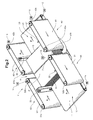
- FIG. 2 shown embodiment of an inventive device 1 'differs from the embodiment according to Figure 1a-1e in that the lateral guide devices 50 for the first conveyor support 10 each contain a guide belt 51, to which at least one feed limit stop 53 is attached instead of at least one feed limit stop, which is arranged downstream of the product stack 2 conveyed on the first belt conveyor 11.
- the trailing feed stops 53 form a guide for the rear in the conveying direction stacking side 6.
- the feed stops 53 of the two side guide devices 50 are aligned with each other and are moved synchronously through the conveying channel. They can be moved through the conveyor channel in such a way that the product stacks 2 are pushed by the feed stops 53 in the conveying direction F and / or are supported towards the rear.
- the product stack 2 is now according to this embodiment in a position in which it is arranged transversely over the strapping gap 4, and in particular in the strapping position, both at its rear stack side 6 and at its front stack side 3 by corresponding stops 43, 53 out and supported.
- the FIG. 3 shows a possible embodiment of the structural design of a side guide 63 for product stack 2.
- the side guide 63 includes a cross-beam 61, to each of which two spaced side guide means 60 are mounted.
- the cross-beam 61 is disposed above the side guide means 60, wherein the side guide means 60 are mounted hanging on the cross-beam 61.
- the side guide means 60 are shown without the associated guide band. Accordingly, the two deflection rollers 62a, 62b are clearly visible.
- the pulleys 62a, 62b include drive wheels with a toothing for driving the guide belts. At least one of the two deflection rollers 62a, 62b is driven by a drive 65.
Abstract
Die Erfindung betrifft eine Vorrichtung (1) zum Umreifen von Produktstapeln (2), enthaltend eine erste Förderauflage (10) und eine, in Förderrichtung (F) der ersten Förderauflage (10) nachfolgend und von dieser beabstandet angeordnete, zweite Förderauflage (20), wobei zwischen der ersten und zweiten Förderauflage (20) und im Wesentlichen quer zur Förderrichtung (F) ein Umreifungsspalt (4) zum Umreifen des Produktstapels (2) mit einem Umreifungsband (7) ausgebildet wird. In Förderrichtung (F) betrachtet ist auf beiden Seiten der zweiten Förderauflage (20) jeweils eine Seitenführungseinrichtung (40) angeordnet, welche die Produktstapel (2) seitlich führen und mit der zweiten Förderauflage (20) einen Förderraum einschliessen. Die Seitenführungseinrichtungen (40) enthalten jeweils mindestens ein umlaufend antreibbares Vorschubbegrenzungselement (43), welches seitlich in den Förderraum vorsteht und dazu ausgelegt ist, zwecks Verhinderung des Auseinanderrutschens von Produkten oder Produkteinheiten des Produktstapels (2) in Förderrichtung (F) mit dem Produktstapel (2) einen Kontaktschluss einzugehen.The invention relates to a device (1) for strapping product stacks (2), comprising a first conveyor support (10) and a second conveyor support (20) arranged downstream of and spaced from the first conveyor support (10) in the conveying direction (F) of the first conveyor support (10). wherein between the first and second conveyor support (20) and substantially transversely to the conveying direction (F), a strapping gap (4) for strapping the product stack (2) with a strapping band (7) is formed. In the conveying direction (F) viewed on both sides of the second conveyor support (20) each have a side guide means (40) are arranged, which laterally guide the product stacks (2) and with the second conveyor support (20) enclose a delivery chamber. The side guiding devices (40) each contain at least one circumferentially drivable feed limiting element (43) which projects laterally into the conveying space and is designed to prevent the slipping of products or product units of the product stack (2) in the conveying direction (F) with the product stack (2 ) to make a contact closure.
Description
Die Erfindung liegt auf dem Gebiet der Fördertechnik und betrifft eine Vorrichtung und ein Verfahren zum Umreifen von Produktstapeln, wobei die Vorrichtung eine erste Förderauflage und eine, in Förderrichtung der ersten Förderauflage nachfolgend und von dieser beabstandet angeordnete, zweite Förderauflage enthält, wobei zwischen der ersten und zweiten Förderauflage und im Wesentlichen quer zur Förderrichtung ein Umreifungsspalt zum Umreifen des Produktstapels mit einem Umreifungsband ausgebildet wird.The invention is in the field of conveyor technology and relates to an apparatus and a method for strapping product stacks, the apparatus comprising a first conveyor support and, in the conveying direction of the first conveyor support and spaced from the second conveyor support, wherein between the first and second conveyor support and substantially transversely to the conveying direction a strapping gap for strapping the product stack is formed with a strapping band.
Flächige Produkte, wie Druckprodukte, werden nach deren Herstellung für den nachfolgenden Transport häufig zu Produktstapeln zusammengefasst und mittels einer Umreifungsvorrichtung einfach oder mehrfach umreift. Die Umreifung sorgt für den Zusammenhalt des Produktstapels.Sheet-like products, such as printed products, are often grouped into product stacks after their production for the subsequent transport and strapped simply or repeatedly by means of a strapping device. The strapping ensures the cohesion of the product stack.
Zur Herstellung der Umreifung müssen die z. B. an einer Stapelvorrichtung erstellten Produktstapel einer Umreifungsvorrichtung zugeführt werden. Hierzu werden die Produktstapel beispielsweise auf einem Förderband in eine Umreifungsposition in der Umreifungsvorrichtung gefördert. Bei diesem Vorgang ist darauf zu achten, dass die Produkte, welche den Produktstapel, bilden nicht gegenseitig verrutschen und der Produktstapel zerfällt.To produce the strapping z. B. created on a stacking device product stack can be supplied to a strapping device. For this purpose, the product stacks are conveyed for example on a conveyor belt into a strapping position in the strapping device. During this process, it must be ensured that the products which form the product stack do not slip each other and the product stack breaks down.
So ist es bekannt, Seitenführungseinrichtungen vorzusehen, welche die auf dem Förderband geförderten Produktstapel seitlich führen.It is thus known to provide lateral guiding devices which laterally guide the product stacks conveyed on the conveyor belt.
Die Veröffentlichungsschriften
Die beschriebenen Vorrichtungen weisen nun den Nachteil auf, dass die Paketanschläge im Betrieb stationär sind. Die Gutstapel kommen mit ihrer vorlaufenden Stapelseite also erst mit Erreichen der Umreifungsposition in Anschlag mit dem Paketanschlag. Während ihrer Förderung in die Umreifungsposition bleiben die Stapel in Förderrichtung nach vorne jedoch ungeführt.The devices described now have the disadvantage that the package stops are stationary during operation. The stacks come with their leading stack side so only with reaching the Umreifungsposition in abutment with the package stop. During their promotion to the Umreifungsposition the stacks remain in the conveying direction forward but unguided.
Auf dem Gebiet der Verarbeitung von Druckereierzeugnissen werden immer komplexere Produkteinheiten hergestellt, welche neben Druckereierzeugnissen, wie Zeitschriften, Zeitungen, Prospekte oder Broschüren, noch Beilagen, wie Warenmuster, Datenträger oder Werbematerial, enthalten. Dies führt dazu, dass die einzelnen Produkteinheiten sowie die aus solchen Produkteinheiten gebildeten Produktstapel unförmig sind. Die Unförmigkeit zeichnet sich insbesondere dadurch aus, dass die einzelnen Produkte oder Produkteinheiten keine konstante Dicke aufweisen. Entsprechend liegend die zu einem Produktstapel zusammengefassten Produkteinheiten nicht mehr flächig aufeinander, wodurch der Produktstapel stark an Stabilität einbüsst.In the field of processing of printed products, more and more complex product units are produced, which contain not only printed matter such as magazines, newspapers, brochures or leaflets, but also supplements such as samples, data carriers or advertising material. This leads to the fact that the individual product units and the product stacks formed from such product units are bulky. The shapelessness is characterized in particular by the fact that the individual products or product units do not have a constant thickness. Accordingly, the product units combined to form a product stack no longer lie flat on top of one another, as a result of which the product stack loses stability considerably.
Dadurch wird die Förderung solcher Produktstapel aus der Stapeleinrichtung bis zur Einnahme der Umreifungsposition und der Ausführung einer ersten Umreifung zunehmend anspruchsvoller. Insbesondere beim Beschleunigen und Abbremsen der Produktstapel besteht die Gefahr, dass Produkte, wie Beilagen oder Warenmuster, bzw. Produkteinheiten aufgrund der auftretenden Trägheitskräfte aus dem Produktstapel rutschen und der Produktstapel zerfällt.As a result, the promotion of such product stacks from the stacking device to the assumption of the strapping position and the execution of a first strapping becomes increasingly demanding. In particular, when accelerating and decelerating the product stack there is a risk that products, such as supplements or samples, or product units due to the inertial forces occurring slip out of the product stack and the product stack is crumbling.
Der Erfindung liegt daher die Aufgabe zugrunde, eine Vorrichtung zum Umreifen von Produktstapeln vorzuschlagen, welche eine optimale Führung der in die Umreifungsposition geförderten Produktstapel zu jeder Seite hin erlaubt.The invention is therefore based on the object to propose a device for strapping product stacks, which allows optimal guidance of the product stack conveyed into the strapping position to each side.
Der Produktstapel soll insbesondere zu jedem Förderzeitpunkt sicher geführt sein. Ferner soll gewährleistet sein, dass beim Beschleunigen und Abbremsen des ungebundenen Produktstapels die Stabilität des Produktstapels jederzeit gewährleistet ist.The product stack should be guided safely in particular at each delivery time. Furthermore, it should be ensured that the stability of the product stack is ensured at any time during acceleration and deceleration of the unbound product stack.
Die Aufgabe wird durch eine Vorrichtung mit den Merkmalen des Anspruch 1 und durch ein Verfahren mit den Merkmalen des Anspruchs 11 gelöst. Weiterbildungen und besondere Ausführungsformen der Erfindung ergeben sich aus den abhängigen Ansprüchen, der Beschreibung und den Zeichnungen.The object is achieved by a device having the features of claim 1 and by a method having the features of
Die Erfindung zeichnet sich nun dadurch aus, dass in Förderrichtung betrachtet auf beiden Seiten der zweiten Förderauflage jeweils eine Seitenführungseinrichtung angeordnet ist, welche die Produktstapel seitlich führen und mit der zweiten Förderauflage einen Förderraum einschliessen. Die Seitenführungseinrichtungen bilden mit der zweiten Förderauflage insbesondere einen Förderkanal aus.The invention is characterized by the fact that viewed in the conveying direction on both sides of the second conveyor support each side guide means is arranged, which guide the product stack laterally and enclose a delivery chamber with the second conveyor support. The side guide devices form, in particular, a delivery channel with the second delivery support.
Die Seitenführungseinrichtungen enthalten ferner jeweils mindestens ein umlaufend antreibbares Vorschubbegrenzungselement, welches seitlich in den Förderraum bzw. Förderkanal vorsteht und dazu ausgelegt ist, zwecks Verhinderung des Wegrutschens bzw. Auseinanderrutschens von Produkten oder Produkteinheiten aus dem Produktstapel in Förderrichtung, mit dem Produktstapel einen Kontaktschluss einzugehen. Unter Kontaktschluss ist in dieser Patentanmeldung ganz allgemein ein physischer Kontakt, wie Reibkontakt oder Anschlag, zu verstehen.The lateral guiding devices furthermore each contain at least one circumferentially drivable feed limiting element, which protrudes laterally into the conveying space or conveying channel and is designed to make a contact closure with the product stack in order to prevent slippage or slipping of products or product units out of the product stack. By contact closure in this patent application is quite generally a physical contact, such as frictional contact or stop to understand.
Die beiden Seitenführungseinrichtungen zur zweiten Förderauflage können über einen gemeinsamen oder über separate Antriebe angetrieben sein.The two side guide devices for the second conveyor support can be driven by a common or separate drives.
Das Vorschubbegrenzungselement ist insbesondere darauf ausgelegt in einem vorderen Abschnitt des Produktstapels auf die seitliche und/oder vordere Stapelseite einzuwirken.The feed limiting element is designed in particular to act on the lateral and / or front stack side in a front section of the product stack.
Gemäss einer Weiterbildung der Erfindung ist das Vorschubbegrenzungselement ein Vorschubbegrenzungsanschlag, welcher im Förderraum in Förderrichtung betrachtet relativ zum Produktstapel vorlaufend bewegbar ist.According to a development of the invention, the feed limiting element is a feed limit stop which, viewed in the conveying direction in the conveying direction, can be moved forwardly relative to the product stack.
Gemäss einer anderen Weiterbildung der Erfindung ist das Vorschubbegrenzungselement ein Reibungselement, welches dazu ausgelegt ist, mit der in Förderrichtung seitlichen Stapelseite einen Reibkontakt herzustellen. Die seitliche Stapelseite ist die der Seitenführungseinrichtung zugewandte Stapelseite.According to another embodiment of the invention, the feed limiting element is a friction element which is designed to produce a frictional contact with the stack side in the conveying direction. The lateral stack side is the side guide device facing stack side.
Die beiden Seitenführungseinrichtungen liegen einander folglich gegenüber, wobei die zweite Förderauflage dazwischen angeordnet ist. Die Vorschubbegrenzungselemente der beiden Seitenführungseinrichtungen werden insbesondere aufeinander ausgerichtet durch den Förderraum bzw. Förderkanal bewegt. Die beiden Seitenführungseinrichtungen werden insbesondere synchron zueinander angetrieben.The two side guide devices are therefore opposite each other, with the second conveyor support disposed therebetween. The feed limiting elements of the two side guide devices are in particular aligned with each other by the conveying space or conveying channel moves. The two side guide devices are driven in particular synchronously to each other.
Das Vorschubbegrenzungselement dient der Führung des Produktstapels in Förderrichtung gegen vorne, wenn dieser mit Erreichen der Umreifungsposition angehalten wird.The feed limiting element serves to guide the product stack in the conveying direction against the front when it is stopped when reaching the strapping position.
Der Produktstapel wird insbesondere durch mindestens zwei aufeinander gelegte Produkteinheiten ausgebildet. Die Produkteinheiten enthalten insbesondere mindestens ein Druckereiprodukt, wie Zeitung, Zeitschrift, Broschüre oder Prospekt. Die Produkteinheiten können auch eine Mehrzahl von ineinander gesteckten Produkten enthalten. Ferner können die Produkteinheiten auch Beilagen, wie Warenmuster, Datenträger oder Werbebeilagen enthalten. Die Produkteinheiten können insbesondere auch Umschläge mit eingesteckten Werbebeilagen sein.The product stack is formed in particular by at least two superimposed product units. The product units contain in particular at least one printed product, such as newspaper, magazine, brochure or prospectus. The product units may also contain a plurality of nested products. Furthermore, the product units may also contain inserts, such as product samples, data carriers or advertising inserts. The product units can in particular also be envelopes with inserted advertising supplements.
Die erste und zweite Förderauflage sind entlang der Förderrichtung seriell, d.h. nacheinander angeordnet.The first and second conveying pads are serial along the conveying direction, i. arranged one after the other.
Der zwischen der ersten und zweiten Förderauflage ausgebildete Umreifungsspalt ist insbesondere Teil eines Umreifungsraumes, innerhalb welchem die Umreifung des Produktstapels stattfindet. Der Umreifungsraum liegt insbesondere in einer vertikal und quer zur Förderrichtung des Produktstapels ausgerichteten Ebene. Der Umreifungsraum kann durch einen Bandführungskanal begrenzt sein.The strapping gap formed between the first and second conveying supports is in particular part of a strapping space within which the strapping of the product stack takes place. The strapping space lies in particular in a plane oriented vertically and transversely to the conveying direction of the product stack. The strapping space may be limited by a band guide channel.
Die Umreifung des Produktstapels erfolgt insbesondere quer zur Förderrichtung des Produktstapels. Das Umreifungsband, mit welchem der Produktstapel umreift wird, kann aus Kunststoff oder Metall sein. Das Umreifungsband kann auch ein textiles Gebilde wie Gewebe oder Schnur aus Kunststoff- oder Naturfasern sein.The strapping of the product stack takes place in particular transversely to the conveying direction of the product stack. The strapping band with which the product stack is strapped can be made of plastic or metal. The strapping can also be a textile structure such as fabric or cord of plastic or natural fibers.
Gemäss einer Weiterbildung der Seitenführungseinrichtungen enthalten diese jeweils mindestens einen, um mindestens zwei voneinander beabstandete Umlenkorgane umlaufend angetriebenen Führungskörper. Der Führungskörper ist insbesondere flexibel. Die Umlenkorgane sind insbesondere senkrecht zur Förderauflage angeordnet.According to a further development of the lateral guiding devices, they each contain at least one guide body which is driven circumferentially by at least two deflecting elements spaced apart from one another. The guide body is particularly flexible. The deflecting elements are arranged in particular perpendicular to the conveyor support.
Das mindestens eine Vorschubbegrenzungselement ist hierbei insbesondere am Führungskörper angeordnet und ist mit diesem umlaufend bewegbar.The at least one feed limiting element is in this case arranged in particular on the guide body and is rotatable with this.
Die zweite Förderauflage wird insbesondere über einen Antrieb angetrieben.The second conveyor support is driven in particular via a drive.
Gemäss einer Weiterbildung der Vorrichtung wird die zweite Förderauflage durch ein umlaufend angetriebenes Förderband, insbesondere eines Bandförderers, ausgebildet.According to a development of the device, the second conveyor support is formed by a circumferentially driven conveyor belt, in particular a belt conveyor.
Die zweite Förderauflage ist insbesondere horizontal ausgerichtet. Die Förderauflage bzw. das Förderband kann in einen Arbeitstisch der Vorrichtung integriert sein.The second conveyor support is in particular aligned horizontally. The conveyor support or the conveyor belt can be integrated in a work table of the device.
Das Vorschubbegrenzungselement dient der Führung und Stützung des in Förderrichtung vorderen Stapelbereichs bzw. der vorderen Stapelseite, insbesondere beim Abbremsen des Produktstapels bei Erreichen der Umreifungsposition.The feed limiting element serves to guide and support the front stacking area in the conveying direction or the front stacking side, in particular during braking of the product stack upon reaching the strapping position.
Gemäss einer Weiterbildung der Vorrichtung ist in Förderrichtung betrachtet auf beiden Seiten der ersten Förderauflage jeweils ebenfalls eine Seitenführungseinrichtung angeordnet. Die beiden Seitenführungseinrichtungen führen den Produktstapel seitlich. Sie bilden zusammen mit der Förderauflage einen Förderraum aus. Der Förderraum ist insbesondere ein Förderkanal.According to a development of the device, viewed in the conveying direction, a lateral guide device is likewise arranged on both sides of the first conveyor support. The two side guide devices guide the product stack laterally. They form together with the conveyor support a pumping room. The delivery chamber is in particular a delivery channel.
Gemäss einer Weiterbildung der Seitenführungseinrichtungen zur ersten Förderauflage enthalten diese mindestens ein umlaufend antreibbares Vorschubbegrenzungselement, welches seitlich in den Förderraum bzw. Förderkanal vorsteht und dazu ausgelegt ist, zwecks Verhinderung des Wegrutschens einzelner Produkte oder Produkteinheiten vom Produktstapel in Förderrichtung, mit dem Produktstapel einen Kontaktschluss einzugehen.According to a further development of the lateral guiding devices for the first conveying support, these contain at least one circumferentially drivable feed limiting element, which protrudes laterally into the conveying space or conveying channel and is designed to make a contact closure with the product stack in order to prevent slippage of individual products or product units from the product stack in the conveying direction.
Gemäss einer Weiterbildung der Erfindung ist das Vorschubbegrenzungselement ein Vorschubbegrenzungsanschlag, welcher im Förderraum in Förderrichtung relativ zum Produktstapel vorlaufend bewegbar ist.According to one embodiment of the invention, the feed limiting element is a feed limit stop, which is movable in advance in the conveying space in the conveying direction relative to the product stack.
Gemäss einer anderen Weiterbildung der Erfindung ist das Vorschubbegrenzungselement ein Reibungselement ist, welches dazu ausgelegt ist, mit der in Förderrichtung seitlichen, d.h. mit der dieser Seitenführungseinrichtung zugewandten, Stapelseite einen Reibkontakt herzustellen.According to another embodiment of the invention, the feed limiting element is a friction element, which is designed to be connected to the side in the conveying direction, i. to make a frictional contact with the stack side facing this side guide device.
Die beiden Seitenführungseinrichtungen liegen einander folglich gegenüber, wobei die zweite Förderauflage dazwischen angeordnet ist.The two side guide devices are therefore opposite each other, with the second conveyor support disposed therebetween.
Die beiden Seitenführungseinrichtungen zur ersten Förderauflage können über einen gemeinsamen oder über separate Antriebe angetrieben sein.The two side guide devices for the first conveyor pad can be driven by a common or separate drives.
Die Vorschubbegrenzungselemente der beiden Seitenführungseinrichtungen werden insbesondere aufeinander ausgerichtet durch den Förderraum bzw. Förderkanal bewegt. Die beiden Seitenführungseinrichtungen werden insbesondere synchron zueinander angetrieben.The feed limiting elements of the two side guide devices are in particular aligned with each other by the conveying space or conveying channel moves. The two side guide devices are driven in particular synchronously to each other.
Die beiden Paarungen von Seitenführungseinrichtungen zur ersten und zweiten Förderauflage werden insbesondere synchron zueinander angetrieben.The two pairings of side guide devices for the first and second conveyor support are in particular driven synchronously with each other.
Das Vorschubbegrenzungselement dient ebenfalls der Führung und Stützung des in Förderrichtung vorderen Stapelbereichs bzw. der vorderen Stapelseite bevor der Produktstapel mit seiner vorderen Stapelseite über den Umreifungsspalt gefördert und in den Einflussbereich der zweiten Förderauflage gelangt.The feed limiting element also serves to guide and support the front stacking area in the conveying direction or the front stacking side before the product stack is conveyed with its front stacking side over the strapping gap and into the area of influence of the second conveyor support.
Muss beispielsweise der geförderte Produktstapel abgebremst werden, bevor dieser seine Umreifungsposition erreicht hat, so stellt das Vorschubbegrenzungselement sicher, dass Produkte oder Produkteinheiten des Produktstapels nicht nach vorne verrutschen können.If, for example, the conveyed product stack has to be braked before it has reached its strapping position, then the feed limiting element ensures that products or product units of the product stack can not slip forward.
Gemäss einer Weiterbildung der Seitenführungseinrichtung zur ersten Förderauflage enthält diese mindestens einen umlaufend antreibbaren Vorschubanschlag, welcher im Förderraum bzw. Förderkanal in Förderrichtung relativ zum Produktstapel nachlaufend bewegbar ist.According to a further development of the lateral guiding device for the first conveyor support, it contains at least one circumferentially drivable feed stop, which in the conveying space or conveying channel in the conveying direction is trailing relative to the product stack.
Der Produktstapel wird über den Vorschubanschlag, insbesondere beim Beschleunigen des Produktstapels, in Förderrichtung betrachtet gegen hinten gestützt.The product stack is supported via the feed stop, especially when accelerating the product stack, viewed in the conveying direction towards the rear.
Der Produktstapel kann ferner über den Vorschubanschlag in Förderrichtung geschoben, insbesondere in die Umreifungsposition geschoben, werden.The product stack can also be pushed over the feed stop in the conveying direction, in particular pushed into the strapping.
Die Vorschubanschläge der beiden Seitenführungseinrichtungen werden insbesondere aufeinander ausgerichtet durch den Förderraum bzw. Förderkanal bewegt. Die beiden Seitenführungseinrichtungen mit den Vorschubanschlägen werden insbesondere synchron zueinander angetrieben.The feed stops of the two side guide devices are in particular aligned with each other by the conveying space or conveying channel moves. The two side guide devices with the feed stops are driven in particular synchronously to each other.
Es ist möglich, dass die Seitenführungseinrichtungen zur ersten Förderauflage jeweils sowohl mindestens ein vorlaufendes Vorschubbegrenzungselement als auch mindestens einen nachlaufenden Vorschubanschlag enthalten. Dadurch wird der Produktstapel in Förderrichtung betrachtet sowohl zu den beiden Seiten hin als auch gegen vorne und gegen hinten geführt und gegen ein Verrutschen gestützt.It is possible that the side guide devices for the first conveyor support each contain both at least one leading feed limiting element and at least one trailing feed stop. As a result, the product stack viewed in the conveying direction is guided both towards the two sides and against the front and against the back and supported against slipping.
Gemäss einer Weiterbildung der Erfindung enthalten die Seitenführungseinrichtungen zur ersten Förderauflage jeweils mindestens einen, um mindestens zwei voneinander beabstandete Umlenkorgane umlaufend angetriebenen Führungskörper. Der Führungskörper ist insbesondere flexibel. Die Umlenkorgane sind insbesondere senkrecht zur Förderauflage angeordnet.According to a further development of the invention, the lateral guiding devices for the first conveying support each comprise at least one guide body, which is driven circumferentially by at least two deflecting members spaced apart from one another. The guide body is particularly flexible. The deflecting elements are arranged in particular perpendicular to the conveyor support.
Ist mindestens ein Vorschubbegrenzungselement vorgesehen, so ist dieses insbesondere am Führungskörper angeordnet und mit diesem umlaufend bewegbar.If at least one feed limiting element is provided, then this is in particular arranged on the guide body and can be moved circumferentially with it.
Ist mindestens ein Vorschubanschlag vorgesehen, so ist dieser insbesondere am Führungskörper angeordnet und mit diesem umlaufend bewegbar.If at least one feed stop provided, this is in particular arranged on the guide body and with this circumferentially movable.
Sind sowohl mindestens ein Vorschubbegrenzungselement als auch mindestens ein Vorschubanschlag vorgesehen, so sind diese an einem gemeinsamen oder an verschiedenen Führungskörper angeordnet und mit diesem umlaufend bewegbar.If both at least one feed limiting element and at least one feed stop are provided, then these are arranged on a common or on different guide body and with this circumferentially movable.
Die zweite Förderauflage wird insbesondere über einen Antrieb angetrieben. Die erste und zweite Förderauflage können über separate oder über einen gemeinsamen Antrieb angetrieben sein. Die beiden Förderauflagen werden insbesondere synchron angetrieben.The second conveyor support is driven in particular via a drive. The first and second conveyor supports can be driven via separate or via a common drive. The two conveyor supports are driven in particular synchronously.
Gemäss einer Weiterbildung der Vorrichtung wird die erste Förderauflage durch ein umlaufend angetriebenes Förderband, insbesondere eines Bandförderers, ausgebildet.According to a development of the device, the first conveyor support is formed by a circumferentially driven conveyor belt, in particular a belt conveyor.
Die erste Förderauflage ist insbesondere horizontal ausgerichtet. Die erste Förderauflage bzw. das Förderband kann in den Arbeitstisch der Vorrichtung integriert sein.The first conveyor support is in particular aligned horizontally. The first conveyor support or the conveyor belt can be integrated in the work table of the device.
Gemäss einer Weiterbildung der Erfindung umfasst die Vorrichtung eine Verschiebeeinrichtung, mittels welcher mindestens eine, insbesondere beide Seitenführungseinrichtungen einer Paarung von Seitenführungseinrichtungen aus ihrer Betriebsposition in eine Passivposition verschiebbar sind.According to a development of the invention, the device comprises a displacement device, by means of which at least one, in particular both lateral guidance devices of a pairing of lateral guidance devices are displaceable from their operating position into a passive position.
Die Verschiebeeinrichtung kann dazu ausgelegt sein, mindestens eine, insbesondere beide Seitenführungseinrichtungen einer Paarung von Seitenführungseinrichtungen über eine translatorische Bewegung oder eine Schwenkbewegung oder einer Kombination von translatorischer Bewegung und Schwenkbewegung zwischen der Betriebsposition und Passivposition zu bewegen.The displacement device can be designed to move at least one, in particular both lateral guidance devices of a pairing of lateral guidance devices via a translatory movement or a pivoting movement or a combination of translatory movement and pivoting movement between the operating position and passive position.
Gemäss einer Weiterbildung der Erfindung umfasst die Vorrichtung eine Verschiebeeinrichtung, mittels welcher mindestens eine, insbesondere beide Seitenführungseinrichtungen einer Paarung von Seitenführungseinrichtungen translatorisch verschiebbar und so die Distanz zwischen den beiden Seitenführungseinrichtungen einstellbar ist. Die Verschiebeeinrichtung kann der weiter oben beschriebenen Verschiebeeinrichtung entsprechen.According to one embodiment of the invention, the device comprises a displacement device, by means of which at least one, in particular both side guide devices of a pairing of lateral guide devices translationally displaceable and so the distance between the two side guide devices adjustable is. The displacement device may correspond to the displacement device described above.
Der Führungskörper einer Seitenführungseinrichtung kann ein Riemen, ein Seil, eine Kette oder ein Band sein. Der Führungskörper ist insbesondere ein Band, welches eine seitliche Führungswand ausbildet. Die Führungswand ist insbesondere senkrecht zur Förderauflage angeordnet.The guide body of a side guide device may be a belt, a rope, a chain or a belt. The guide body is in particular a band which forms a lateral guide wall. The guide wall is arranged in particular perpendicular to the conveyor support.
Das Band kann insbesondere in der Art eines endlosen Förderbandes ausgebildet sein. Das Band kann insbesondere eine Modulbandkette mit einer Mehrzahl von miteinander verbundenen Modulbandgliedern sein.The band may in particular be designed in the manner of an endless conveyor belt. In particular, the band may be a modular ribbon with a plurality of modular ribbon members connected together.
Das Umlenkorgan kann eine Umlenkrolle sein. Eine oder beide der mindestens zwei Umlenkrollen kann angetrieben sein. Die Drehachse der Umlenkorgane ist jeweils insbesondere senkrecht zur Förderauflage angeordnet.The deflecting member may be a deflection roller. One or both of the at least two pulleys may be driven. The axis of rotation of the deflection is in each case arranged in particular perpendicular to the conveyor support.
Das Vorschubbegrenzungselement kann elastische Eigenschaften aufweisen. Das Vorschubbegrenzungselement kann insbesondere aus einem elastischen Material, wie einem Elastomer, ausgebildet sein oder dieses enthalten.The feed limiting element may have elastic properties. The feed limiting element may in particular be made of or contain an elastic material, such as an elastomer.
Der Vorschubbegrenzungsanschlag kann leistenförmig ausgebildet sein. Der Vorschubbegrenzungsanschlag kann sich vertikal zur Förderauflage erstrecken.The feed limit stop may be strip-shaped. The feed limit stop can extend vertically to the conveyor support.
Das als Reibungselement ausgebildete Vorschubbegrenzungselement kann z. B. als Bürste ausgebildet sein oder in den Förderraum vorstehende Lamellen aufweisen.Trained as a friction element feed limiting element can, for. B. be designed as a brush or have in the delivery chamber projecting fins.
Der Vorschubanschlag kann ebenfalls leistenförmig ausgebildet sein. Der Vorschubanschlag kann sich vertikal zur Förderauflage erstrecken.The feed stop may also be strip-shaped. The feed stop may extend vertically to the conveyor support.
Die Seitenführungseinrichtungen können beispielsweise an einer oberhalb der Seitenführungseinrichtungen angeordneten Halterung befestigt, insbesondere aufgehängt, sein. Die Halterung kann beispielsweise ein quer zur Förderrichtung über die Förderauflage angeordnete Traverse in Form eines Querträgers sein.The side guide devices can be fastened, for example, to a holder arranged above the side guide devices, in particular suspended, be. The holder may be, for example, a cross member arranged transversely to the conveying direction over the conveyor support in the form of a cross member.
Die Erfindung betrifft auch ein Verfahren zum Umreifen von Produktstapeln mit einer Vorrichtung gemäss obiger Beschreibung. Das Verfahren umfasst die folgenden Schritte:
- Fördern eines auf der ersten Förderauflage aufliegenden Produktstapels in Förderrichtung,
- Übernehmen des durch die erste Förderauflage, insbesondere über den Umreifungsspalt hinaus, geförderten Produktstapels durch die zweite Förderauflage und
- Weiterfördern des Produktstapels in eine Umreifungsposition, in welcher der Produktstapel quer über dem Umreifungsspalt angeordnet ist,
- Umreifen des Produktstapels mit einem Umreifungsband,
- Weiterfördern des umreiften Produktstapels,
- Conveying a product stack resting on the first conveyor support in the conveying direction,
- Taking over the product stack conveyed through the first conveyor support, in particular beyond the strapping nip, by the second conveyor support and
- Further conveying the product stack into a strapping position, in which the product stack is arranged transversely over the strapping gap,
- Strapping the product stack with a strapping band,
- Further conveying the strapped product stack,
Der Produktstapel liegt folglich in der Umreifungsposition mit einem in Förderrichtung betrachtet hinteren Stapelabschnitt auf der ersten Förderauflage und mit einem vorderen Stapelabschnitt auf der zweiten Förderauflage.Consequently, the product stack lies in the strapping position with a rear stack section viewed in the conveying direction on the first conveyor support and with a front stack section on the second conveyor support.
Das Umreifen des Produktstapels mit einem Umreifungsband wird auch als Binden bezeichnet. Die Produkte bzw. Produkteinheiten des Produktstapels werden durch die Umreifung zusammengehalten und gegen ein gegenseitiges Verrutschen gesichert.The strapping of the product stack with a strapping band is also referred to as binding. The products or product units of the product stack are held together by the strapping and secured against mutual slippage.
Die Bindung kann eine Quer- oder Längsbindung sein. Es können mehrere Bindungen vorgenommen werden. Eine kombinierte Quer- und Längsbindung weist den Vorteil auf, dass diese dem Produktstapel zu allen Seiten hin einen guten Zusammenhalt vermittelt.The bond may be a transverse or longitudinal bond. Several bindings can be made. A combined transverse and longitudinal binding has the advantage that it gives the product stack a good cohesion on all sides.
Gemäss einer Weiterbildung des Verfahrens ist das Vorschubbegrenzungselement ein Vorschubbegrenzungsanschlag, welcher vorlaufend zum Produktstapel in Förderrichtung mitbewegt wird, derart dass Produkte oder Produkteinheiten des Produktstapels beim Abbremsen des Produktstapels am Vorschubbegrenzungsanschlag in Anschlag kommen.According to a development of the method, the feed limitation element is a feed limit stop, which is moved ahead of the product stack in the conveying direction such that products or product units of the product stack come into abutment against the feed limit stop when the product stack is being decelerated.
Gemäss einer anderen Weiterbildung des Verfahrens ist das Vorschubbegrenzungselement ein Reibungselement, welches seitlich oder vorlaufend zum Produktstapel in Förderrichtung mitbewegt wird, derart dass in Förderrichtung betrachtet die seitliche Stapelseite des Produktstapels beim Abbremsen des Produktstapels mit dem Vorschubbegrenzungselement einen seitlichen Reibkontakt eingeht, so dass Produkte oder Produkteinheiten des Produktstapels nicht in Förderrichtung nach vorne wegrutschen können.According to another development of the method, the feed limiting element is a friction element, which is moved laterally or leading to the product stack in the conveying direction, such that viewed in the conveying direction, the lateral stacking side of the product stack during braking of the product stack with the feed limiting element enters into a lateral frictional contact, so that products or product units of the product stack can not slip forward in the conveying direction.
Das Vorschubbegrenzungselement kann mit einer kleineren Geschwindigkeit als die dazugehörige zweite Förderauflage bewegt werden. Das Vorschubbegrenzungselement kann auch mit derselben Geschwindigkeit wie die zweite Förderauflage bewegt werden. Die Geschwindigkeiten der Förderauflage und des Vorschubbegrenzungselements können insbesondere synchron sein.The feed limiting element can be moved at a lower speed than the associated second conveyor support. The feed limiting element can also be moved at the same speed as the second conveyor support. The speeds of the conveyor support and the feed limiting element may in particular be synchronous.
Das umlaufend bewegte Vorschubbegrenzungselement, insbesondere wenn es sich um einen Vorschubbegrenzungsanschlag handelt, kann insbesondere vor dem Hineinbewegen der vorderen Stapelseite zwischen die Seitenführungseinrichtungen um die Umlenkorgane aus einem Rückführabschnitt in den Förderraum bzw. Förderkanal eingeschwenkt und dem Produktstapel vorlaufend durch den Förderraum bewegt werden.The circumferentially moving feed limiting element, in particular when it is a feed limit stop, can in particular be pivoted in front of the front stacking side between the side guide means around the deflecting from a return section in the conveying space or conveying channel and the product stack to be moved forward through the pumping chamber.
Der Produktstapel kommt bei diesem Vorgang mit der vorderen Stapelseite in Anschlag mit dem Vorschubbegrenzungsanschlag.During this process, the product stack comes into abutment with the front stacking side with the feed limit stop.
Das umlaufend bewegte Vorschubbegrenzungselement kann auch gleichzeitig mit dem Hineinbewegen des Produktstapels zwischen die Seitenführungseinrichtungen um die Umlenkorgane aus einem Rückführabschnitt in den Förderraum bzw. Förderkanal eingeschwenkt und seitlich vom Produktstapel mitlaufend durch den Förderraum bewegt werden.The circumferentially moving feed limiting element can also be pivoted in at the same time as the product stack is moved in between the lateral guide devices around the deflecting elements from a return section into the conveying space or conveying channel and laterally moved from the product stack through the conveying space.
Der Produktstapel wird insbesondere gemeinsam mit dem Vorschubbegrenzungselement in die Umreifungsposition bewegt.The product stack is in particular moved together with the feed limiting element in the Umreifungsposition.
Bei der Weiterförderung des umreiften Produktstapels wird das Vorschubbegrenzungselement am Ende des Förderraums bzw. Förderkanals um das Umlenkorgan wieder in den Rückführabschnitt bewegt und entgegen der Förderrichtung zurückbewegt.In the further promotion of the strapped product stack, the feed limiting element is moved at the end of the delivery chamber or conveying channel to the deflection member back into the return section and moved back against the conveying direction.
Die Erfindung weist den Vorteil, dass die Produkte bzw. Produkteinheiten beim Abbremsen des Produktstapels nicht mehr aufgrund der Trägheitskraft nach vorne wegrutschen können, wodurch der Produktstapel zerfallen würde.The invention has the advantage that the products or product units can no longer slip forward due to the inertial force when the product stack is being decelerated, as a result of which the product stack would disintegrate.
Dadurch können auch Produktstapel mit unförmigen Produkten bzw. Produkteinheiten, welche z. B. nicht flächig aufeinander liegen, problemlos verarbeitet werden.As a result, product stacks with bulky products or product units which z. B. are not flat on each other, are processed easily.
Ferner ist die Qualität des gebundenen Produktstapels sehr hoch, da die Produkteinheiten des Produktstapels bei der Umreifung nicht nur zur Seite sondern auch nach vorne ausgerichtet sind.Furthermore, the quality of the bound product stack is very high because the product units of the product stack are aligned not only to the side but also to the front during strapping.
Die Erfindung erlaubt zudem auch das Umreifen der Produktstapel in schnelleren Zyklen, welche unweigerlich mit höheren Beschleunigungen verbunden sind. So sind dank der vorliegenden Erfindung beispielsweise Zykluszeiten von unter 2 Sekunden möglich. Die Produktstapel werden dabei mit Geschwindigkeiten von 0.5 bis 1 m/s bewegt. Entsprechend steil sind daher die Brems- und Beschleunigungsrampen vor und nach dem Umreifen des Produktstapels im Stillstand und entsprechend gross die daraus resultierenden Trägheitskräfte.The invention also allows the strapping of the product stack in faster cycles, which are inevitably associated with higher accelerations. So are Thanks to the present invention, for example, cycle times of less than 2 seconds are possible. The product stacks are moved at speeds of 0.5 to 1 m / s. Correspondingly steep are therefore the braking and acceleration ramps before and after strapping the product stack at a standstill and correspondingly large the resulting inertial forces.
Da die Vorschubbegrenzungselemente im Betrieb nicht als feststehende Anschlagelemente ausgebildet sind sondern vielmehr in Förderrichtung mitbewegt werden, können die in Förderrichtung in die Umreifungsposition bewegten Produktstapel auch nicht auf die Vorschubbegrenzungselemente aufprallen. Dadurch wird eine Beschädigung der Produktstapel oder ein Zurückprallen der Produktstapel von den Vorschubbegrenzung selementen verhindert.Since the feed limiting elements are not designed as stationary stop elements during operation but rather are moved in the conveying direction, the product stacks moving in the conveying direction into the strapping position can not impinge on the feed limiting elements. This prevents damage to the product stacks or rebounding of the product stacks by the feed limitation elements.
Ein weiterer Vorteil der vorlaufenden Erfindung liegt auch darin, dass bestehende Umreifungsvorrichtungen vergleichsweise einfach und kostengünstig mit den erfindungsgemässen, technischen Merkmalen nachrüstbar sind.Another advantage of the preceding invention is that existing strapping devices can be retrofitted comparatively easily and inexpensively with the technical features according to the invention.
Beispiele der Erfindung sind in den Zeichnungen dargestellt und nachfolgend beschrieben. Es zeigen schematisch:
- Fig. 1a - 1e
- eine perspektivische Ansicht einer erfindungsgemässen Vorrichtung gemäss einer ersten Ausführungsform in verschiedenen Betriebspositionen;
- Fig. 2
- eine perspektivische Ansicht einer erfindungsgemässen Vorrichtung gemäss einer zweiten Ausführungsform;
- Fig. 3
- eine perspektivische Ansicht der Befestigung der Seitenführungseinrichtungen.
- Fig. 1a - 1e
- a perspective view of an inventive device according to a first embodiment in different operating positions;
- Fig. 2
- a perspective view of an inventive device according to a second embodiment;
- Fig. 3
- a perspective view of the attachment of the side guide devices.
Die
Die Vorrichtung 1 enthält einen ersten Bandförderer 11 mit einem ersten Förderband, welches eine horizontale Förderauflage 10 ausbildet. Der erste Bandförderer 11 bzw. das Förderband wird mittels eines Antriebes 5 angetrieben.The device 1 comprises a
Die Vorrichtung 1 enthält im Weiteren einen in Förderrichtung F im Anschluss an den ersten Bandförderer 11 angeordneten, zweiten Bandförderer 21 mit einem zweiten Förderband, welches ebenfalls eine horizontale Förderauflage 20 ausbildet. Der zweite Bandförderer 21 bzw. das Förderband wird mittels eines Antriebes 5 angetrieben. Der erste und zweite Bandförderer 11, 21 werden synchron zueinander angetrieben.The apparatus 1 further includes a
Die beiden Bandförderer 11, 21 sind in Förderrichtung F voneinander beabstandet, so dass zwischen dem ersten und zweiten Bandförderer 11, 21 ein quer zur Förderrichtung F verlaufender Umreifungsspalt 4 ausgebildet wird.The two
Seitlich vom ersten Bandförderer 11 ist jeweils eine Seitenführungseinrichtung 30 angeordnet. Der erste Bandförderer 11 und die beiden Seitenführungseinrichtungen 30 bilden zusammen einen Förderkanal für die Produktstapel 2 aus.Side of the
Die Seitenführungseinrichtungen 30 umfassen jeweils ein Führungsband 31, welches um zwei in Förderrichtung F hintereinander und voneinander beabstandet angeordnete Umlenkrollen 32a, 32b umlaufend geführt ist. Die Umlenkrollen 32a, 32b und entsprechend das Führungsband 31 sind senkrecht zur Förderauflage 10 ausgerichtet. Entsprechend bildet das Führungsband 31 eine seitliche, vertikale Führungswand aus.The
Am Führungsband 31 ist ein Vorschubbegrenzungsanschlag 33 angeordnet, welcher mit dem Führungsband 31 umlaufend mitbewegt wird. Der Vorschubbegrenzungsanschlag 33 bildet für den Produktstapel 2 im Förderkanal einen vorlaufenden Anschlag aus.On
Ferner ist jeweils seitlich vom zweiten Bandförderer 21 ebenfalls eine Seitenführungseinrichtung 40 angeordnet. Der zweite Bandförderer 21 und die beiden Seitenführungseinrichtungen 40 bilden zusammen ebenfalls einen Förderkanal für die Produktstapel 2, 2' aus.Furthermore, in each case laterally from the
Die beiden Seitenführungseinrichtungen 40 umfassen jeweils ebenfalls ein Führungsband 41, welches um zwei in Förderrichtung F hintereinander und voneinander beabstandet angeordnete Umlenkrollen 42a, 42b umlaufend geführt ist. Die Umlenkrollen 42a, 42b und entsprechend das Führungsband 41 sind senkrecht zur Förderauflage 20 ausgerichtet. Entsprechend bildet das Führungsband 41 eine seitliche, vertikale Führungswand aus.The two
Am Führungsband 41 ist ein Vorschubbegrenzungsanschlag 43 angeordnet, welcher mit dem Führungsband 41 umlaufend mitbewegt wird. Der Vorschubbegrenzungsanschlag 43 bildet für den Produktstapel 2, 2' im Förderkanal einen vorlaufenden Anschlag aus.On the
Die beiden Paarungen von Seitenführungseinrichtungen 30, 40 werden über Antriebe 5 synchron zueinander angetrieben.The two pairings of
Zur Umreifung eines Produktstapels 2, welcher zum Beispiel in einer StapelVorrichtung erstellt wurde, wird der Produktstapel 2 dem ersten Bandförderer 10 zugefördert. Sowohl das Förderband des Bandförderers 10 als auch die seitlichen Führungsbänder 31 der Seitenführungseinrichtungen 30 werden hierbei angetrieben.For strapping a
Bevor der Produktstapel 2 jedoch mit seiner vorderen Stapelseite 3 zwischen die beiden Seitenführungseinrichtungen 30 bewegt wird, werden die Vorschubbegrenzungsanschläge 33 der beiden Führungsbänder 31 aus dem Rückführabschnitt in den Förderkanal eingeschwenkt, so dass diese gegenüber dem zugeführten Produktstapel 2 vorlaufend angeordnet sind (siehe
Die Bewegung der Führungsbänder 31 und der Vorschubbegrenzungsanschläge 33 ist mit der Zuförderung des Produktstapels 2 synchronisiert.The movement of the
Die beiden, vorlaufenden und aufeinander ausgerichteten Vorschubbegrenzungsanschläge 33 bilden einen Anschlag für die in Förderrichtung F vordere Stapelseite 3 aus und werden gemeinsam mit dem Produktstapel 2 in Förderrichtung F bewegt. Sollte der Produktstapel 2 aus bestimmten Gründen abgebremst werden müssen, so verhindern die Vorschubbegrenzungsanschläge 33 ein Wegrutschen von Produkten oder Produkteinheiten nach vorne.The two, leading and aligned feed limit stops 33 form a stop for the front in the conveying direction
Erreicht die vordere Stapelseite 3 den Umreifungsspalt 4, werden die Vorschubbegrenzungsanschläge 33 aus dem Förderkanal ausgeschwenkt und in den Rückführabschnitt bewegt (siehe
Der Produktstapel 2 wird nun durch den ersten Bandförderer 10 in Förderrichtung F über den Umreifungsspalt 4 hinaus weitergefördert.The
Bevor der Produktstapel 2 jedoch mit seiner vorlaufenden Stirnkante 3 zwischen die beiden Seitenführungseinrichtungen 40 des zweiten Bandförderers 20 bewegt wird, werden die Vorschubbegrenzungsanschläge 43 der beiden Führungsbänder 41 aus dem Rückführabschnitt in den Förderkanal eingeschwenkt, so dass diese gegenüber dem den Umreifungsspalt 4 in Förderrichtung F überquerenden Produktstapel 2 vorlaufend angeordnet sind.However, before the
Mit Erreichen der Umreifungsposition werden die Bandförderer 11, 21 sowie auch die Führungsbänder 31, 41 mit ihren Vorschubbegrenzungsanschlägen 33, 43 abgebremst und angehalten. Der Produktstapel 2 liegt in der Umreifungsposition quer über dem Umreifungsspalt 4 (siehe
Die Vorschubbegrenzungsanschläge 43 verhindern nun beim Anhalten des Stapels 2 in der Umreifungsposition ein Wegrutschen von Produkten oder Produkteinheiten nach vorne.The feed limit stops 43 prevent now when stopping the
Der Produktstapel 2 wird nun in der Umreifungsposition umreift und anschliessend in Förderrichtung F weitergefördert. Hierzu werden die Bandförderer 11, 21 sowie die Führungsbänder 31, 41 wieder in Bewegung versetzt.The
Der umreifte Produktstapel 2' wird mittels des zweiten Bandförderers 21 aus der Umreifungsposition herausgefördert (siehe
Die in
Die Vorschubanschläge 53 der beiden Seitenführungseinrichtungen 50 sind aufeinander ausgerichtet und werden synchron durch den Förderkanal bewegt. Sie können derart durch den Förderkanal bewegt werden, dass die Produktstapel 2 durch die Vorschubanschläge 53 in Förderrichtung F geschoben und/oder gegen hinten gestützt werden.The feed stops 53 of the two
Der Produktstapel 2 ist nun gemäss dieser Ausführungsform in einer Position, in welcher dieser quer über dem Umreifungsspalt 4 angeordnet ist, und insbesondere in der Umreifungsposition, sowohl an seiner hinteren Stapelseite 6 als auch an seiner vorderen Stapelseite 3 durch entsprechende Anschläge 43, 53 geführt und gestützt. Die
Die Seitenführungseinrichtungen 60 sind ohne das dazugehörige Führungsband dargestellt. Entsprechend sind jeweils die beiden Umlenkrollen 62a, 62b gut sichtbar. Die Umlenkrollen 62a, 62b enthalten Antriebsräder mit einer Zahnung zum Antreiben der Führungsbänder. Mindestens eine der beiden Umlenkrollen 62a, 62b wird über einen Antrieb 65 angetrieben.The side guide means 60 are shown without the associated guide band. Accordingly, the two
Claims (12)
in Förderrichtung (F) betrachtet auf beiden Seiten der zweiten Förderauflage (20) jeweils eine Seitenführungseinrichtung (40) angeordnet ist, welche die Produktstapel (2) seitlich führen und mit der zweiten Förderauflage (20) einen Förderraum einschliessen, und die Seitenführungseinrichtungen (40) jeweils mindestens ein umlaufend antreibbares Vorschubbegrenzungselement (43) enthalten, welches seitlich in den Förderraum vorsteht und dazu ausgelegt ist, zwecks Verhinderung des Auseinanderrutschens von Produkten oder Produkteinheiten des Produktstapels (2) in Förderrichtung (F), mit dem Produktstapel (2) einen Kontaktschluss einzugehen.Device (1) for strapping product stacks (2), comprising a first conveyor support (10) and, in the conveying direction (F) of the first conveyor support (10) following and spaced therefrom, second conveyor support (20), wherein between the first and second conveyor support (20) and substantially transversely to the conveying direction (F) a strapping gap (4) for strapping the product stack (2) with a strapping band (7) is formed, characterized in that
in the conveying direction (F) a lateral guide device (40) is arranged on both sides of the second conveyor support (20), which guide the product stacks (2) laterally and enclose a conveyor chamber with the second conveyor support (20), and the lateral guiding devices (40) in each case at least one circumferentially drivable Vorschubbegrenzungselement (43) included, which projects laterally into the delivery chamber and is designed to prevent the slipping of products or product units of the product stack (2) in the conveying direction (F), with the product stack (2) to make a contact closure ,
Applications Claiming Priority (1)
| Application Number | Priority Date | Filing Date | Title |
|---|---|---|---|
| CH01813/14A CH710406A1 (en) | 2014-11-25 | 2014-11-25 | Device for strapping stacks of products. |
Publications (2)
| Publication Number | Publication Date |
|---|---|
| EP3025970A1 true EP3025970A1 (en) | 2016-06-01 |
| EP3025970B1 EP3025970B1 (en) | 2017-11-08 |
Family
ID=54557337
Family Applications (1)
| Application Number | Title | Priority Date | Filing Date |
|---|---|---|---|
| EP15195222.3A Active EP3025970B1 (en) | 2014-11-25 | 2015-11-18 | Device for bundling product stacks |
Country Status (4)
| Country | Link |
|---|---|
| US (1) | US20160144986A1 (en) |
| EP (1) | EP3025970B1 (en) |
| AU (1) | AU2015258249B2 (en) |
| CH (1) | CH710406A1 (en) |
Families Citing this family (3)
| Publication number | Priority date | Publication date | Assignee | Title |
|---|---|---|---|---|
| DE102009040700A1 (en) * | 2009-09-10 | 2011-03-24 | Krones Ag | Method and device for the production of containers |
| CN113619840A (en) * | 2020-05-06 | 2021-11-09 | 四川卡库机器人科技有限公司 | Moving platform for banding machine, banding device and banding method |
| CN116835035B (en) * | 2023-09-01 | 2023-11-03 | 泰州市榕兴医疗用品股份有限公司 | Medical gauze stacking and binding integrated machine |
Citations (6)
| Publication number | Priority date | Publication date | Assignee | Title |
|---|---|---|---|---|
| CH591383A5 (en) * | 1976-01-27 | 1977-09-15 | Grapha Holding Ag | |
| DE19920531A1 (en) | 1999-05-05 | 2000-11-16 | Smb Schwede Maschb Gmbh | Hoop-casing machine for hoop-casing stack of goods, especially stack of newspapers or similar, by means of hoop-casing strip has work table and hoop-casing device on it with strip guidance element that is free of guide channel sections |
| EP1273542A1 (en) * | 2001-07-05 | 2003-01-08 | Grapha-Holding AG | Device for transporting printed products stacked up on a support |
| DE10203903A1 (en) | 2002-01-31 | 2003-08-14 | Smb Schwede Maschb Gmbh | Strapping machine for binding stack of e.g. periodicals has controller provided to secondary conveyors, and which has motor that control speed of guide walls and position of feed plates |
| EP1439143A1 (en) * | 2003-01-14 | 2004-07-21 | Ferag AG | Method and device for forming stacks of printed products, comprising an additional sheet |
| EP2157038A1 (en) * | 2008-08-18 | 2010-02-24 | Ferag AG | Intermediary storage device and stacking unit with intermediary storage device |
Family Cites Families (10)
| Publication number | Priority date | Publication date | Assignee | Title |
|---|---|---|---|---|
| US3225684A (en) * | 1964-09-02 | 1965-12-28 | Signode Corp | Machine for tying bundles |
| US4312266A (en) * | 1980-05-30 | 1982-01-26 | Ovalstrapping, Inc. | Object-turning apparatus for a high-speed strapping machine |
| NL8105908A (en) * | 1981-12-30 | 1983-07-18 | Metaverpa Nv | MECHANISM FOR TURNING AN OBJECT ABOUT A VERTICAL AXIS OVER A PARTICULAR ANGLE. |
| US4769970A (en) * | 1987-07-23 | 1988-09-13 | Jcc Engineering Co., Ltd | Automatic packing machine |
| DE4007264A1 (en) * | 1990-03-08 | 1990-07-05 | Smb Schwede Maschinenbau Gmbh | Packing station for wrapping objects with diagonal cross strips |
| DE4138800A1 (en) * | 1991-11-26 | 1993-05-27 | Signode Bernpak Gmbh | METHOD AND DEVICE FOR AVOIDING OPERATING INTERRUPTIONS ON MACHINES FOR STRAPPING PACKAGES |
| EP0894721B1 (en) * | 1997-07-04 | 2003-01-29 | Ferag AG | Method and device for tying single objects or stacks of objects |
| DE59806405D1 (en) * | 1997-07-09 | 2003-01-09 | Ferag Verpakkingstechniek B V | Method and device for strapping individual objects or stacks of objects. |
| DE10148698A1 (en) * | 2001-10-02 | 2003-04-24 | Mosca G Maschf | Rotary device for conveyor systems |
| US6789469B1 (en) * | 2003-04-29 | 2004-09-14 | Illinois Tool Works, Inc. | Bundling assembly for strapping machine |
-
2014
- 2014-11-25 CH CH01813/14A patent/CH710406A1/en not_active Application Discontinuation
-
2015
- 2015-11-18 EP EP15195222.3A patent/EP3025970B1/en active Active
- 2015-11-19 AU AU2015258249A patent/AU2015258249B2/en not_active Ceased
- 2015-11-24 US US14/949,996 patent/US20160144986A1/en not_active Abandoned
Patent Citations (6)
| Publication number | Priority date | Publication date | Assignee | Title |
|---|---|---|---|---|
| CH591383A5 (en) * | 1976-01-27 | 1977-09-15 | Grapha Holding Ag | |
| DE19920531A1 (en) | 1999-05-05 | 2000-11-16 | Smb Schwede Maschb Gmbh | Hoop-casing machine for hoop-casing stack of goods, especially stack of newspapers or similar, by means of hoop-casing strip has work table and hoop-casing device on it with strip guidance element that is free of guide channel sections |
| EP1273542A1 (en) * | 2001-07-05 | 2003-01-08 | Grapha-Holding AG | Device for transporting printed products stacked up on a support |
| DE10203903A1 (en) | 2002-01-31 | 2003-08-14 | Smb Schwede Maschb Gmbh | Strapping machine for binding stack of e.g. periodicals has controller provided to secondary conveyors, and which has motor that control speed of guide walls and position of feed plates |
| EP1439143A1 (en) * | 2003-01-14 | 2004-07-21 | Ferag AG | Method and device for forming stacks of printed products, comprising an additional sheet |
| EP2157038A1 (en) * | 2008-08-18 | 2010-02-24 | Ferag AG | Intermediary storage device and stacking unit with intermediary storage device |
Also Published As
| Publication number | Publication date |
|---|---|
| EP3025970B1 (en) | 2017-11-08 |
| AU2015258249B2 (en) | 2020-07-09 |
| AU2015258249A1 (en) | 2016-06-09 |
| CH710406A1 (en) | 2016-05-31 |
| US20160144986A1 (en) | 2016-05-26 |
Similar Documents
| Publication | Publication Date | Title |
|---|---|---|
| DE2138119C3 (en) | Device for stacking blanks or the like. Stackable | |
| EP1882651B1 (en) | Device and method for separating a flow of articles | |
| EP1686084B1 (en) | Device for gathering printed sheets along a conveying route of a circulating conveyer | |
| EP2199240B1 (en) | Device for separating parts | |
| DE1561728B2 (en) | BOW CONVEYOR | |
| DE102013002754A1 (en) | Apparatus for laying out printed products supplied in a product stream in two separate stacks | |
| EP0031515A1 (en) | Apparatus for producing packaging blanks by separation from a continuously moving web | |
| DE60113580T2 (en) | Cutting machine for a variety of kitchen and / or toilet paper rolls | |
| EP0498068A1 (en) | Folder, in which the folded articles are transported using transportation means ,idlers and conveyors | |
| EP2277812B1 (en) | Method for lateral alignment of products with level base, in particular printed products and transport device for carrying out the method | |
| CH662330A5 (en) | DEVICE FOR GENERATING SPACES IN A MOVING STREAM OF OVERLAPPING PAPER SHEETS. | |
| EP3025970B1 (en) | Device for bundling product stacks | |
| DE102006011642A1 (en) | Device for forming stacks of flat products | |
| EP2202158B1 (en) | Strapping device and method for operation | |
| DE3423479C2 (en) | ||
| DE1237504B (en) | Device for producing an even conveying flow | |
| EP1231176B1 (en) | Device for feeding printed products in a conveyor duct | |
| EP1528023A1 (en) | Method and device for changing a stream of flat objects | |
| EP2994402B1 (en) | Manipulator | |
| DE202015008899U1 (en) | Plant for forming a folded object | |
| DE1115500B (en) | Transport device for card-shaped recording media, especially punch cards | |
| DE102009045319B4 (en) | Formateinstellvorrichtung | |
| EP1219558A2 (en) | Method and device for collating flat obects | |
| EP2316767B1 (en) | Device and method for manufacturing printed product stacks | |
| EP1522513A2 (en) | Device for separating flat products arranged in shingled formation |
Legal Events
| Date | Code | Title | Description |
|---|---|---|---|
| PUAI | Public reference made under article 153(3) epc to a published international application that has entered the european phase |
Free format text: ORIGINAL CODE: 0009012 |
|
| AK | Designated contracting states |
Kind code of ref document: A1 Designated state(s): AL AT BE BG CH CY CZ DE DK EE ES FI FR GB GR HR HU IE IS IT LI LT LU LV MC MK MT NL NO PL PT RO RS SE SI SK SM TR |
|
| AX | Request for extension of the european patent |
Extension state: BA ME |
|
| STAA | Information on the status of an ep patent application or granted ep patent |
Free format text: STATUS: REQUEST FOR EXAMINATION WAS MADE |
|
| 17P | Request for examination filed |
Effective date: 20161125 |
|
| RBV | Designated contracting states (corrected) |
Designated state(s): AL AT BE BG CH CY CZ DE DK EE ES FI FR GB GR HR HU IE IS IT LI LT LU LV MC MK MT NL NO PL PT RO RS SE SI SK SM TR |
|
| GRAP | Despatch of communication of intention to grant a patent |
Free format text: ORIGINAL CODE: EPIDOSNIGR1 |
|
| STAA | Information on the status of an ep patent application or granted ep patent |
Free format text: STATUS: GRANT OF PATENT IS INTENDED |
|
| RIC1 | Information provided on ipc code assigned before grant |
Ipc: B65B 27/08 20060101ALI20170504BHEP Ipc: B65B 35/24 20060101ALI20170504BHEP Ipc: B65B 35/40 20060101ALI20170504BHEP Ipc: B65B 13/18 20060101ALI20170504BHEP Ipc: B65B 13/02 20060101AFI20170504BHEP Ipc: B65G 15/12 20060101ALI20170504BHEP |
|
| INTG | Intention to grant announced |
Effective date: 20170522 |
|
| GRAS | Grant fee paid |
Free format text: ORIGINAL CODE: EPIDOSNIGR3 |
|
| GRAA | (expected) grant |
Free format text: ORIGINAL CODE: 0009210 |
|
| STAA | Information on the status of an ep patent application or granted ep patent |
Free format text: STATUS: THE PATENT HAS BEEN GRANTED |
|
| AK | Designated contracting states |
Kind code of ref document: B1 Designated state(s): AL AT BE BG CH CY CZ DE DK EE ES FI FR GB GR HR HU IE IS IT LI LT LU LV MC MK MT NL NO PL PT RO RS SE SI SK SM TR |
|
| REG | Reference to a national code |
Ref country code: GB Ref legal event code: FG4D Free format text: NOT ENGLISH |
|
| REG | Reference to a national code |
Ref country code: CH Ref legal event code: EP Ref country code: AT Ref legal event code: REF Ref document number: 943899 Country of ref document: AT Kind code of ref document: T Effective date: 20171115 |
|
| REG | Reference to a national code |
Ref country code: IE Ref legal event code: FG4D Free format text: LANGUAGE OF EP DOCUMENT: GERMAN |
|
| REG | Reference to a national code |
Ref country code: CH Ref legal event code: NV Representative=s name: FREI PATENTANWALTSBUERO AG, CH |
|
| REG | Reference to a national code |
Ref country code: DE Ref legal event code: R096 Ref document number: 502015002298 Country of ref document: DE |
|
| REG | Reference to a national code |
Ref country code: NL Ref legal event code: MP Effective date: 20171108 |
|
| REG | Reference to a national code |
Ref country code: LT Ref legal event code: MG4D |
|
| PG25 | Lapsed in a contracting state [announced via postgrant information from national office to epo] |
Ref country code: FI Free format text: LAPSE BECAUSE OF FAILURE TO SUBMIT A TRANSLATION OF THE DESCRIPTION OR TO PAY THE FEE WITHIN THE PRESCRIBED TIME-LIMIT Effective date: 20171108 Ref country code: NO Free format text: LAPSE BECAUSE OF FAILURE TO SUBMIT A TRANSLATION OF THE DESCRIPTION OR TO PAY THE FEE WITHIN THE PRESCRIBED TIME-LIMIT Effective date: 20180208 Ref country code: SE Free format text: LAPSE BECAUSE OF FAILURE TO SUBMIT A TRANSLATION OF THE DESCRIPTION OR TO PAY THE FEE WITHIN THE PRESCRIBED TIME-LIMIT Effective date: 20171108 Ref country code: ES Free format text: LAPSE BECAUSE OF FAILURE TO SUBMIT A TRANSLATION OF THE DESCRIPTION OR TO PAY THE FEE WITHIN THE PRESCRIBED TIME-LIMIT Effective date: 20171108 Ref country code: LT Free format text: LAPSE BECAUSE OF FAILURE TO SUBMIT A TRANSLATION OF THE DESCRIPTION OR TO PAY THE FEE WITHIN THE PRESCRIBED TIME-LIMIT Effective date: 20171108 Ref country code: NL Free format text: LAPSE BECAUSE OF FAILURE TO SUBMIT A TRANSLATION OF THE DESCRIPTION OR TO PAY THE FEE WITHIN THE PRESCRIBED TIME-LIMIT Effective date: 20171108 |
|
| PG25 | Lapsed in a contracting state [announced via postgrant information from national office to epo] |
Ref country code: RS Free format text: LAPSE BECAUSE OF FAILURE TO SUBMIT A TRANSLATION OF THE DESCRIPTION OR TO PAY THE FEE WITHIN THE PRESCRIBED TIME-LIMIT Effective date: 20171108 Ref country code: LV Free format text: LAPSE BECAUSE OF FAILURE TO SUBMIT A TRANSLATION OF THE DESCRIPTION OR TO PAY THE FEE WITHIN THE PRESCRIBED TIME-LIMIT Effective date: 20171108 Ref country code: BG Free format text: LAPSE BECAUSE OF FAILURE TO SUBMIT A TRANSLATION OF THE DESCRIPTION OR TO PAY THE FEE WITHIN THE PRESCRIBED TIME-LIMIT Effective date: 20180208 Ref country code: HR Free format text: LAPSE BECAUSE OF FAILURE TO SUBMIT A TRANSLATION OF THE DESCRIPTION OR TO PAY THE FEE WITHIN THE PRESCRIBED TIME-LIMIT Effective date: 20171108 Ref country code: GR Free format text: LAPSE BECAUSE OF FAILURE TO SUBMIT A TRANSLATION OF THE DESCRIPTION OR TO PAY THE FEE WITHIN THE PRESCRIBED TIME-LIMIT Effective date: 20180209 Ref country code: IS Free format text: LAPSE BECAUSE OF FAILURE TO SUBMIT A TRANSLATION OF THE DESCRIPTION OR TO PAY THE FEE WITHIN THE PRESCRIBED TIME-LIMIT Effective date: 20180308 |
|
| PG25 | Lapsed in a contracting state [announced via postgrant information from national office to epo] |
Ref country code: CZ Free format text: LAPSE BECAUSE OF FAILURE TO SUBMIT A TRANSLATION OF THE DESCRIPTION OR TO PAY THE FEE WITHIN THE PRESCRIBED TIME-LIMIT Effective date: 20171108 Ref country code: SK Free format text: LAPSE BECAUSE OF FAILURE TO SUBMIT A TRANSLATION OF THE DESCRIPTION OR TO PAY THE FEE WITHIN THE PRESCRIBED TIME-LIMIT Effective date: 20171108 Ref country code: EE Free format text: LAPSE BECAUSE OF FAILURE TO SUBMIT A TRANSLATION OF THE DESCRIPTION OR TO PAY THE FEE WITHIN THE PRESCRIBED TIME-LIMIT Effective date: 20171108 Ref country code: DK Free format text: LAPSE BECAUSE OF FAILURE TO SUBMIT A TRANSLATION OF THE DESCRIPTION OR TO PAY THE FEE WITHIN THE PRESCRIBED TIME-LIMIT Effective date: 20171108 Ref country code: CY Free format text: LAPSE BECAUSE OF FAILURE TO SUBMIT A TRANSLATION OF THE DESCRIPTION OR TO PAY THE FEE WITHIN THE PRESCRIBED TIME-LIMIT Effective date: 20171108 |
|
| REG | Reference to a national code |
Ref country code: DE Ref legal event code: R097 Ref document number: 502015002298 Country of ref document: DE |
|
| PG25 | Lapsed in a contracting state [announced via postgrant information from national office to epo] |
Ref country code: RO Free format text: LAPSE BECAUSE OF FAILURE TO SUBMIT A TRANSLATION OF THE DESCRIPTION OR TO PAY THE FEE WITHIN THE PRESCRIBED TIME-LIMIT Effective date: 20171108 Ref country code: LU Free format text: LAPSE BECAUSE OF NON-PAYMENT OF DUE FEES Effective date: 20171118 Ref country code: IT Free format text: LAPSE BECAUSE OF FAILURE TO SUBMIT A TRANSLATION OF THE DESCRIPTION OR TO PAY THE FEE WITHIN THE PRESCRIBED TIME-LIMIT Effective date: 20171108 Ref country code: SM Free format text: LAPSE BECAUSE OF FAILURE TO SUBMIT A TRANSLATION OF THE DESCRIPTION OR TO PAY THE FEE WITHIN THE PRESCRIBED TIME-LIMIT Effective date: 20171108 Ref country code: PL Free format text: LAPSE BECAUSE OF FAILURE TO SUBMIT A TRANSLATION OF THE DESCRIPTION OR TO PAY THE FEE WITHIN THE PRESCRIBED TIME-LIMIT Effective date: 20171108 |
|
| REG | Reference to a national code |
Ref country code: BE Ref legal event code: MM Effective date: 20171130 |
|
| REG | Reference to a national code |
Ref country code: IE Ref legal event code: MM4A |
|
| PLBE | No opposition filed within time limit |
Free format text: ORIGINAL CODE: 0009261 |
|
| STAA | Information on the status of an ep patent application or granted ep patent |
Free format text: STATUS: NO OPPOSITION FILED WITHIN TIME LIMIT |
|
| PG25 | Lapsed in a contracting state [announced via postgrant information from national office to epo] |
Ref country code: MT Free format text: LAPSE BECAUSE OF FAILURE TO SUBMIT A TRANSLATION OF THE DESCRIPTION OR TO PAY THE FEE WITHIN THE PRESCRIBED TIME-LIMIT Effective date: 20171108 |
|
| REG | Reference to a national code |
Ref country code: FR Ref legal event code: ST Effective date: 20180905 |
|
| 26N | No opposition filed |
Effective date: 20180809 |
|
| PG25 | Lapsed in a contracting state [announced via postgrant information from national office to epo] |
Ref country code: FR Free format text: LAPSE BECAUSE OF NON-PAYMENT OF DUE FEES Effective date: 20180108 Ref country code: IE Free format text: LAPSE BECAUSE OF NON-PAYMENT OF DUE FEES Effective date: 20171118 |
|
| PG25 | Lapsed in a contracting state [announced via postgrant information from national office to epo] |
Ref country code: BE Free format text: LAPSE BECAUSE OF NON-PAYMENT OF DUE FEES Effective date: 20171130 Ref country code: SI Free format text: LAPSE BECAUSE OF FAILURE TO SUBMIT A TRANSLATION OF THE DESCRIPTION OR TO PAY THE FEE WITHIN THE PRESCRIBED TIME-LIMIT Effective date: 20171108 |
|
| PG25 | Lapsed in a contracting state [announced via postgrant information from national office to epo] |
Ref country code: MC Free format text: LAPSE BECAUSE OF FAILURE TO SUBMIT A TRANSLATION OF THE DESCRIPTION OR TO PAY THE FEE WITHIN THE PRESCRIBED TIME-LIMIT Effective date: 20171108 Ref country code: HU Free format text: LAPSE BECAUSE OF FAILURE TO SUBMIT A TRANSLATION OF THE DESCRIPTION OR TO PAY THE FEE WITHIN THE PRESCRIBED TIME-LIMIT; INVALID AB INITIO Effective date: 20151118 |
|
| PG25 | Lapsed in a contracting state [announced via postgrant information from national office to epo] |
Ref country code: MK Free format text: LAPSE BECAUSE OF FAILURE TO SUBMIT A TRANSLATION OF THE DESCRIPTION OR TO PAY THE FEE WITHIN THE PRESCRIBED TIME-LIMIT Effective date: 20171108 |
|
| PG25 | Lapsed in a contracting state [announced via postgrant information from national office to epo] |
Ref country code: TR Free format text: LAPSE BECAUSE OF FAILURE TO SUBMIT A TRANSLATION OF THE DESCRIPTION OR TO PAY THE FEE WITHIN THE PRESCRIBED TIME-LIMIT Effective date: 20171108 |
|
| PG25 | Lapsed in a contracting state [announced via postgrant information from national office to epo] |
Ref country code: PT Free format text: LAPSE BECAUSE OF FAILURE TO SUBMIT A TRANSLATION OF THE DESCRIPTION OR TO PAY THE FEE WITHIN THE PRESCRIBED TIME-LIMIT Effective date: 20171108 |
|
| PG25 | Lapsed in a contracting state [announced via postgrant information from national office to epo] |
Ref country code: AL Free format text: LAPSE BECAUSE OF FAILURE TO SUBMIT A TRANSLATION OF THE DESCRIPTION OR TO PAY THE FEE WITHIN THE PRESCRIBED TIME-LIMIT Effective date: 20171108 |
|
| GBPC | Gb: european patent ceased through non-payment of renewal fee |
Effective date: 20191118 |
|
| PG25 | Lapsed in a contracting state [announced via postgrant information from national office to epo] |
Ref country code: GB Free format text: LAPSE BECAUSE OF NON-PAYMENT OF DUE FEES Effective date: 20191118 |
|
| REG | Reference to a national code |
Ref country code: AT Ref legal event code: MM01 Ref document number: 943899 Country of ref document: AT Kind code of ref document: T Effective date: 20201118 |
|
| PG25 | Lapsed in a contracting state [announced via postgrant information from national office to epo] |
Ref country code: AT Free format text: LAPSE BECAUSE OF NON-PAYMENT OF DUE FEES Effective date: 20201118 |
|
| P01 | Opt-out of the competence of the unified patent court (upc) registered |
Effective date: 20230526 |
|
| PGFP | Annual fee paid to national office [announced via postgrant information from national office to epo] |
Ref country code: DE Payment date: 20231121 Year of fee payment: 9 Ref country code: CH Payment date: 20231201 Year of fee payment: 9 |