EP3025950A1 - Small watercraft for leisure use - Google Patents
Small watercraft for leisure use Download PDFInfo
- Publication number
- EP3025950A1 EP3025950A1 EP14829853.2A EP14829853A EP3025950A1 EP 3025950 A1 EP3025950 A1 EP 3025950A1 EP 14829853 A EP14829853 A EP 14829853A EP 3025950 A1 EP3025950 A1 EP 3025950A1
- Authority
- EP
- European Patent Office
- Prior art keywords
- small watercraft
- disposed
- room
- space
- deck
- Prior art date
- Legal status (The legal status is an assumption and is not a legal conclusion. Google has not performed a legal analysis and makes no representation as to the accuracy of the status listed.)
- Withdrawn
Links
- 239000000463 material Substances 0.000 claims abstract description 16
- 238000000034 method Methods 0.000 abstract description 4
- 238000010586 diagram Methods 0.000 description 7
- 230000000694 effects Effects 0.000 description 3
- 239000011521 glass Substances 0.000 description 3
- 239000003795 chemical substances by application Substances 0.000 description 1
- 238000004891 communication Methods 0.000 description 1
- 230000000295 complement effect Effects 0.000 description 1
- 230000008602 contraction Effects 0.000 description 1
- 238000007796 conventional method Methods 0.000 description 1
- 239000003365 glass fiber Substances 0.000 description 1
- 238000012423 maintenance Methods 0.000 description 1
- 238000005192 partition Methods 0.000 description 1
- 238000000638 solvent extraction Methods 0.000 description 1
- 238000005507 spraying Methods 0.000 description 1
- 229920006337 unsaturated polyester resin Polymers 0.000 description 1
Images










Classifications
-
- B—PERFORMING OPERATIONS; TRANSPORTING
- B63—SHIPS OR OTHER WATERBORNE VESSELS; RELATED EQUIPMENT
- B63B—SHIPS OR OTHER WATERBORNE VESSELS; EQUIPMENT FOR SHIPPING
- B63B29/00—Accommodation for crew or passengers not otherwise provided for
- B63B29/02—Cabins or other living spaces; Construction or arrangement thereof
-
- B—PERFORMING OPERATIONS; TRANSPORTING
- B63—SHIPS OR OTHER WATERBORNE VESSELS; RELATED EQUIPMENT
- B63B—SHIPS OR OTHER WATERBORNE VESSELS; EQUIPMENT FOR SHIPPING
- B63B19/00—Arrangements or adaptations of ports, doors, windows, port-holes, or other openings or covers
-
- B—PERFORMING OPERATIONS; TRANSPORTING
- B63—SHIPS OR OTHER WATERBORNE VESSELS; RELATED EQUIPMENT
- B63B—SHIPS OR OTHER WATERBORNE VESSELS; EQUIPMENT FOR SHIPPING
- B63B19/00—Arrangements or adaptations of ports, doors, windows, port-holes, or other openings or covers
- B63B19/02—Clear-view screens; Windshields
-
- B—PERFORMING OPERATIONS; TRANSPORTING
- B63—SHIPS OR OTHER WATERBORNE VESSELS; RELATED EQUIPMENT
- B63B—SHIPS OR OTHER WATERBORNE VESSELS; EQUIPMENT FOR SHIPPING
- B63B27/00—Arrangement of ship-based loading or unloading equipment for cargo or passengers
- B63B27/14—Arrangement of ship-based loading or unloading equipment for cargo or passengers of ramps, gangways or outboard ladders ; Pilot lifts
-
- B—PERFORMING OPERATIONS; TRANSPORTING
- B63—SHIPS OR OTHER WATERBORNE VESSELS; RELATED EQUIPMENT
- B63B—SHIPS OR OTHER WATERBORNE VESSELS; EQUIPMENT FOR SHIPPING
- B63B34/00—Vessels specially adapted for water sports or leisure; Body-supporting devices specially adapted for water sports or leisure
-
- B—PERFORMING OPERATIONS; TRANSPORTING
- B63—SHIPS OR OTHER WATERBORNE VESSELS; RELATED EQUIPMENT
- B63B—SHIPS OR OTHER WATERBORNE VESSELS; EQUIPMENT FOR SHIPPING
- B63B45/00—Arrangements or adaptations of signalling or lighting devices
- B63B45/06—Arrangements or adaptations of signalling or lighting devices the devices being intended to illuminate vessels' decks or interior
-
- B—PERFORMING OPERATIONS; TRANSPORTING
- B63—SHIPS OR OTHER WATERBORNE VESSELS; RELATED EQUIPMENT
- B63B—SHIPS OR OTHER WATERBORNE VESSELS; EQUIPMENT FOR SHIPPING
- B63B49/00—Arrangements of nautical instruments or navigational aids
-
- B—PERFORMING OPERATIONS; TRANSPORTING
- B63—SHIPS OR OTHER WATERBORNE VESSELS; RELATED EQUIPMENT
- B63B—SHIPS OR OTHER WATERBORNE VESSELS; EQUIPMENT FOR SHIPPING
- B63B19/00—Arrangements or adaptations of ports, doors, windows, port-holes, or other openings or covers
- B63B2019/0007—Ship's windows
- B63B2019/0038—Ship's windows, other than bull's eyes
-
- B—PERFORMING OPERATIONS; TRANSPORTING
- B63—SHIPS OR OTHER WATERBORNE VESSELS; RELATED EQUIPMENT
- B63B—SHIPS OR OTHER WATERBORNE VESSELS; EQUIPMENT FOR SHIPPING
- B63B19/00—Arrangements or adaptations of ports, doors, windows, port-holes, or other openings or covers
- B63B19/08—Ports or like openings in vessels' sides or at the vessels' bow or stern
- B63B2019/086—Stern ports, e.g. for ferries or Ro-Ro-vessels
Definitions
- the present invention relates to a technique for a small watercraft.
- the small watercrafts include a small watercraft for leisure use that is used for sports, recreations, and the like (see Patent Literature 1).
- the small watercraft for leisure use includes compartments such as a pilot house, an owner room, a guest room, a salon, a galley, a shower room, and a lounge space.
- the small watercraft is formed with a hull and a deck curved to have an inner surface with a curved shape.
- the compartment of the small watercraft is formed with walls (inner wall materials) in an inboard section standing in a vertical direction.
- the present invention is made in view of the situation described above, and an object of the present invention is to provide a technique related to a small watercraft with which, compared with a configuration with an inboard section having standing walls, an inboard space is more effectively used so that a larger space of the compartment can be achieved.
- a small watercraft for leisure use according to the present invention includes a compartment, in which the compartment is formed with an inner wall material provided on an inboard section in such a manner as to be curved in accordance with a shape of the inboard section.
- the compartment includes a beam member exposed in the compartment.
- the compartment includes a lighting device disposed to the beam member.
- the small watercraft further includes a pilot house, and a windshield disposed on a front side of the pilot house, in which the windshield is disposed across left and right end portions of the pilot house.
- an inboard space of a small watercraft is effectively used, so that a space of a compartment can be configured to be large.
- a small watercraft 1 according to an embodiment of the present invention is described with reference to Figs. 1 to 23 .
- the small watercraft 1 is a small watercraft for leisure use, and is used for sports, recreations, and the like.
- the small watercraft 1 has an overall length of approximately 12 m, a weight of approximately 10 tons, and a complement of 12 persons.
- the small watercraft 1 includes an engine (not illustrated), and is configured to obtain thrust by driving a propeller (not illustrated) with the engine serving as a power source.
- the small watercraft 1 includes a deck 1b on an upper side of a hull 1a and a cabin 1c on an upper side of the deck 1b.
- the small watercraft 1 includes a lounge space 8 and a pilot house 2 that are in the cabin 1c.
- the small watercraft 1 has a width of the deck 1b smaller than a width of the hull 1a, and side portions of the deck 1b positioned more on the inner side than side portions of the hull 1a.
- the hull 1a and the deck 1b of the small watercraft 1 are mainly made of an FRP material.
- Outer shapes of the hull 1a and the deck 1b are formed by spraying gelcoat on a mold coated with a release agent (wax), and after the gelcoat is dried (cured), stacking layers of glass fiber roving, unsaturated polyester resin, and the like until a designed thickness is achieved.
- a release agent wax
- the hull 1a of the small watercraft 1 is provided with the deck 1b, the cabin 1c, an engine room 1d, a radar arm 1e, a pair of left and right air introduction ports 1f, 1f, a rear deck 1g, and a transom gate 1h.
- the deck 1b covers an upper part of the hull 1a and forms a compartment and the like.
- the deck 1b is provided with a plurality of windows (a front roof window 11, a rear roof window 12, and a pair of left and right side windows 13, 13) for daylighting in the compartment in the inboard section and a mooring device 22.
- the front roof window 11 and the rear roof window 12 are widows for daylighting in the inboard section.
- the front roof window 11 is disposed at a portion of the deck 1b more on the front side than the cabin 1c and on a bow side of the deck 1b, in a non-openable (fixed) state.
- the front roof window 11 is disposed at a portion that is separated from the bow by a distance corresponding to approximately one fifth of the hull length.
- the rear roof window 12 is disposed at a portion of the deck 1b more on the front side than the cabin 1c and on a stem side of the deck 1b, in an openable state.
- the rear roof window 12 is separated from the bow by a distance corresponding to approximately two fifths of the hull length.
- the rear roof window 12 can be opened by an opening angle that is larger than 90° about a stem side portion.
- the rear roof window 12 is configured to be tightly closable with a plurality of unillustrated fasteners.
- the rear roof window 12 in an opened state can be used for ventilating the compartment, for going to and coming back from a bow deck (deck 1b), or for other like purposes. More specifically, an unillustrated ladder supporting unit is formed on a window frame of the rear roof window 12.
- the rear roof window 12 is configured in such a manner that, in the opened state, a ladder 100 can be supported by the ladder supporting unit.
- the ladder 100 to be used is configured to be extendable and retractable, and is contained in a container box 53 in an owner room 3 described later (see Fig. 15 ).
- the ladder 100 is configured to be taken out from a side surface opening 53b of the container box 53 to be used.
- the present embodiment is not limited to the ladder 100, and a gangway may be used.
- the side windows 13, 13 of the small watercraft 1 are disposed on left and right side portions of the deck 1b.
- the side window 13 is disposed to extend from an approximately center portion in a bow and stem direction to a portion that is separated from the bow by a distance corresponding to one fifth of the hull length.
- the pair of left and right side windows 13 each have an inboard section side divided into two sections of a bow side window 13a and a stem side window 13b.
- the pair of left and right side windows 13 each have the bow side window 13a serving as a window for the owner room 2 and the stem side window 13b serving as a window for a salon 4 and a galley 5.
- the small watercraft 1 can have a space large enough to dispose the front roof window 11 and the rear roof window 12 (a space large enough to dispose two roof windows on the deck 1b arranged in the bow and stem direction).
- the small watercraft 1 can have the pair of left and right side windows 13 that are large in the bow and stem direction.
- the cabin 1c protrudes beyond the deck 1b to cover the rear side of the deck 1b, whereby the pilot house 2 and the lounge space 8 are formed.
- a person can go into and come out from the cabin 1c through a gateway 1c of the rear deck 1g.
- the cabin 1c includes a windshield 14, a pair of left and right side windows 15, 15, a movable roof 16, and a window door 45 serving as the gateway 1i of the rear deck 1g.
- the cabin 1c has an opening formed in a roof portion.
- the windshield 14 of the cabin 1c is disposed across left and right end portions of the pilot house 2.
- the windshield 14 has a left and right direction width that is approximately the same as a left and right direction width of the pilot house 2.
- the small watercraft 1 features a better view from a helmsman seat 21 a in the pilot house 2 compared with a configuration without the windshield 14 disposed across the left and right end portions of the pilot house 2.
- the movable roof 16 is provided in the opening formed in the ceiling portion of the cabin 1c. More specifically, the movable roof 16 is disposed above the helmsman seat 21a and an assistant helmsman seat 21b. As illustrated in Figs. 21 and 22 , the movable roof 16 includes a fixed portion 16a and a movable portion 16b, and is openable and closable through sliding movement of the movable portion 16b.
- the fixed portion 16a and the movable portion 16b of the movable roof 16 are each formed by fitting a glass piece on a frame.
- the movable roof 16 has crosspieces 16c formed in the movable portion 16b to achieve high glass strength. Thus, the movable portion 16b of the movable roof 16 can stably operate.
- the window door 45 serving as the gateway 1i, is provided at a center portion of a stem side end portion of the cabin 1c.
- the window door 45 is formed as a sliding door that moves in a left-and-right direction to be opened and closed.
- the window door 45 is entirely glassed.
- the fixed portions on both left and right sides of the window door 45, at the stem side end portion of the cabin 1c, are glassed.
- the small watercraft 1 includes the engine room 1d, the radar arm 1e, the pair of left and right air introduction ports 1f, 1f, the rear deck 1g, and the transom gate 1h.
- An engine is disposed in the engine room 1d of the small watercraft 1.
- the engine room 1d is provided in a space (inboard section) surrounded by the hull 1a and the deck 1b.
- the engine room 1d is disposed below the cabin 1c.
- the engine room 1d is disposed below the rear deck 1g.
- the radar arm 1e of the small watercraft 1 is provided with a radar (not illustrated) and supports the radar.
- the radar arm 1e is integrally formed with the hull 1a.
- the radar arm 1e is formed to have an arch shape.
- the radar arm 1e extends from an upper end from the hull 1a in an inclined manner in an upper rear direction, and surrounds side portions of the deck 1b, rear side portions of the cabin 1c, and a rear upper portion of the cabin 1c.
- the air introduction ports 1f of the small watercraft 1 are used for introducing intake air for the engine into the engine room 1d in the inboard section from the outside.
- the air introduced into the inboard section through the air introduction ports 1f is supplied to the engine room 1d through piping (not illustrated).
- the rear deck 1g is disposed in a stem portion and more on a rear side than the cabin 1c, and thus the rear deck 1g is disposed above the engine room 1d.
- An opening 1m, communicating with the engine room 1d, is formed in an approximately center portion of the rear deck 1g.
- the rear deck 1g is provided with a flap door 41 that can be opened and closed to close the opening 1m.
- the small watercraft 1 has the flap door 41 of the rear deck 1g serving as a top board of the engine room 1d.
- maintenance work for the engine 23 in the engine room 1d can be performed while the flap door 41 of the rear deck 1g is in the open state.
- the flap door 41 can be opened and closed by raising and lowering the bow side of the flap door 41 about a hinge 41a, provided at an end portion on the stem side, serving as a rotational axis.
- the bow side end portion of the flap door 41 is connected to an electric cylinder 42 provided in the engine room 1d.
- the flap door 41 can be opened and closed through extension and contraction of the electric cylinder 42.
- a trench In is formed at an edge portion over the entire circumference of the opening 1m on an upper surface of the rear deck 1g.
- the trench In has a shape similar to the flap door 41, and a size large enough to fit the flap door 41 with a gap in between.
- the trench In is formed to have a depth that is approximately the same as the thickness of the flap door 41.
- the trench 1n supports the flap door 41 in such a manner that the upper surface of the rear deck 1g is flush with the upper surface of the flap door 41 covering the opening 1m.
- the trench 1n and a groove 1p of the rear deck 1g may have bent end portions.
- the transom gate 1h of the small watercraft 1 is disposed in the stem side rear end portion.
- the transom gate 1h is formed as a part of a transom surrounding the rear deck 1g.
- the transom gate 1h is rotatable.
- the transom gate 1h is used as a path to move from the small watercraft 1 to a land (for example, a pier) by being rotated to be laid rearward.
- the small watercraft 1 includes inboard compartments.
- the small watercraft 1 includes the pilot house 2, the owner room 3, the salon 4, the galley 5, a guest room 6, a shower room 7, a lounge space 8, and the like.
- the compartments (the pilot house 2, the owner room 3, the salon 4, the galley 5, the guest room 6, the shower room 7, the lounge space 8, and the like) of the small watercraft 1 are provided in a space surrounded by the hull 1a, the deck 1b, and/or the cabin 1c.
- the small watercraft 1 includes the pilot house 2 and the lounge space 8 disposed in the cabin 1c.
- the small watercraft 1 includes the pilot house 2 disposed on the bow side, and the lounge space 8 disposed on the stem side, in the cabin 1c.
- the small watercraft 1 has the rear deck 1g and the cabin 1c with approximately the same floor (sole) height.
- the pilot house 2 is disposed to be a compartment that comes first in the watercraft (the cabin 1c) from the gateway 1i of the rear deck 1g.
- the small watercraft 1 has the owner room 3, the salon 4, the galley 5, the guest room 6, the shower room 7, and the like at positions that are more on the bow side than the cabin 1c and below the floor of the cabin 1c.
- the small watercraft 1 has a protruding portion 2a as a portion of the pilot house 2 on the bow side in the cabin 1c protruding upward to have a space large enough for the owner room 3, the salon 4, the galley 5, the guest room 6, the shower room 7, and the like.
- the pilot house 2 includes the helmsman seat 21a, the assistant helmsman seat 21b, and a control panel 46.
- the pilot house 2 has the helmsman seat 21a and the control panel 46 on a starboard side relative the bow.
- the control panel 46 in the pilot house 2 is provided on a side surface of the protruding portion 2a in the cabin 1c.
- the pilot house 2 has the assistant helmsman seat 21b disposed on a port side relative to the bow.
- the pilot house 2 includes a path 1j on the side surface of the protruding portion 2a in the cabin 1c and at an approximately center portion between the helmsman seat 21a and the assistant helmsman seat 21b.
- the path 1j extends toward the bow to lead to the owner room 3, the salon 4, the galley 5, the guest room 6, the shower room 7, and the like in the inboard section.
- a person in charge of steering the small watercraft 1 sits on the helmsman seat 21a to perform the steering.
- the helmsman seat 21a is disposed to face the control panel 46.
- the helmsman seat 21a is movable in upper, lower, front, and rear directions to be suitable for the body of the person in charge of steering.
- the control panel 46 includes operation tools, meters, and the like for the small watercraft 1 in a concentrated manner.
- the control panel 46 is provided with monitors 47, analog meters 48, a handle 49, a throttle lever 50, a joy stick 51, and the like.
- the control panel 46 has a plurality of the analog meters 48 arranged side-by-side in the left and right direction and disposed above the monitors 47.
- Each of the analog meters 48 has a metallic ring 48a attached to an edge portion and eight recesses 48b formed at an equal interval on an outer side surface of the ring 48a (see Fig. 14 ).
- the control panel 46 has the handle 49 and the joy stick 51 disposed on a display screen side of the monitors 47.
- the control panel 46 has the throttle lever 50 disposed on the starboard side.
- the assistant helmsman seat 21b is arranged side-by-side with the helmsman seat 21a, and is disposed on the port side.
- the assistant helmsman seat 21b is disposed to face a side surface of the protruding portion 2a in the cabin 1c.
- the assistant helmsman seat 21b is disposed on a partially raised floor of the cabin 1c.
- An air-conditioner outlet 2b is disposed on a portion of the side surface of the protruding portion 2a in front of the assistant helmsman seat 21b.
- a skylight 2c, in communication with the guest room 6, is disposed at a portion of an upper surface of the protruding portion 2a in front of the assistant helmsman seat 21b close to the windshield 14.
- a cup holder and the like are disposed on a port side surface close to the assistant helmsman seat 21b.
- a cabinet 2d is provided on a port side surface behind the assistant helmsman seat 21b. The cabinet 2d stores a storage type LCD TV 2e.
- the owner room 3 is a main bedroom.
- the owner room 3 is more on the bow side than any other one of the compartments.
- the owner room 3 is disposed adjacent to a farther side (bow side) of the path 1j with a door 3a in between.
- a bed 52 for two persons is disposed at the center of the owner room 3.
- the bed 52 in the owner room 3 includes a bed board 52a and a bedding 52b such as a mattress.
- the bed 52 in the owner room 3 has the container box 53 on the bed board.
- the container box 53 includes a container portion divided into two sections.
- the container box 53 includes floor openings 53a, 53a (hatched portions in Fig. 15 ) for respective sections on a floor of the bed board 52a and a side surface opening 53b on a side surface of the bed board 52a.
- the owner room 3 of the small watercraft 1 has curved side surfaces in accordance with the shape of the hull 1a of the small watercraft 1.
- the owner room 3 has inner wall materials 54 provided on the inboard section (side portions of the inboard section) in accordance with the shape of the curved side surfaces.
- An unillustrated audio device and an operation device 56a for the audio device are provided on a port side surface of the owner room 3 in an embedded manner.
- a speaker 56b is provided on a ceiling of the owner room 3.
- An air-conditioner outlet 56c that is additional equipment is provided at an upper portion of the side surface of the owner room 3 on the port side.
- the outlet 56 may be disposed on both starboard and port sides in the owner room 3.
- the cabinet 56d is disposed on a rear-starboard side in the owner room 3.
- the bow side windows 13a of the side windows 13 are disposed on side surfaces of the owner room 3 on the starboard and port sides.
- the front roof window 11 is disposed at approximately the center of the ceiling of the owner room 3.
- the daylighting in the owner room 3 with sunlight can be achieved through the bow side windows 13a of the side windows 13 formed on the hull 1a and the front roof window 11 formed on the deck 1b.
- the owner room 3 is the compartment that is curved in accordance with the shape of the hull 1a, and has the side surfaces provided with the inner wall materials 54.
- the space of the inboard section can be more effectively used, so that the owner room 3 can have a larger space (living space) compared with a configuration in which walls (inner wall materials) stand vertically in the inboard section.
- the unillustrated audio device and the operation device 56a for the audio device are embedded in the side surface of the owner room 3.
- the small watercraft 1 needs no inboard space for placing the audio device and the operation device 56a for the audio device, whereby the inboard space can be effectively used, so that the owner room 3 can have a larger space (living space).
- the inner wall materials 54 of the owner room 3 of the small watercraft 1 include a cushion material.
- the owner room 3 has a plurality of the inner wall materials 54 (cushion materials) that are long in the bow and stem direction arranged in the upper and lower direction in a clinker built fashion.
- the owner room 3 is formed with the plurality of inner wall materials 54, including the cushion materials, arranged in the upper and lower direction in the clinker built fashion as described above.
- the inboard space can be effectively used, so that the owner room 3 can have a larger space (living space).
- the owner room 3 with a better appearance can be achieved.
- the owner room 3 is formed with a plurality of beam members 55 exposed in the owner room 3 in the inboard section (side portions of the inboard section).
- the owner room 3 is provided with the beam members 55 arranged at a predetermined interval in the bow and stem direction in the watercraft.
- the small watercraft 1 with the owner room 3 as a compartment provided with the beam members 55 exposed in the owner room 3 can have a strength improved with the beam members 55 exposed in the owner room 3 unlike in the configuration where the beam members 55 are hidden to make the space of the owner room 3 smaller.
- a lighting device 57 is disposed at an approximately center portion in the upper and lower direction of each of the beam members 55 that are disposed to be exposed in the owner room 3 of the small watercraft 1.
- the lighting device 57 is disposed to be embedded in a notch 55a formed at the center portion in the upper and lower direction of the beam members 55.
- the lighting device 57 including a light source 57a such as an incandescent light, a fluorescent light, or an LED lighting device is disposed in a space that is formed to extend toward the inner side of the beam members 55 from the notch 55a.
- a side surface 55b of the notch 55a is illuminated with light from the light source 57a of the lighting device 57.
- the lighting device 57 is for indirect lighting using the beam members 55.
- the lighting device 57 may be provided with a light distribution plate 57b including a glass plate for dispersing the light in the light radiated directions of the incandescent light, the fluorescent light, or the LED lighting device 57c.
- the lighting device 57 is disposed by using the beam members 55 exposed in the owner room 3, whereby the number of the lighting device 57 in the owner room 3 can be increased without sacrificing the space in the owner room 3 (compartment).
- the salon 4 illustrated in Fig. 9 and 10 is what is known as a lounge.
- the salon 4 is disposed on the stem side of the owner room 3 and on the starboard side of the path 1j.
- the salon 4 includes a sofa 58, a table 59, and a monitor 60.
- the salon 4 includes a container box 61 disposed below the sofa 58.
- the salon 4 has a ceiling provided with the rear roof window 12.
- the salon 4 has the stem side window 13b disposed on a side surface on the starboard side. Daylighting in the salon 4 with sunlight can be achieved through the rear roof window 12 formed in the deck 1b and the stem side window 13b of the side window 13 formed in the hull 1a.
- the galley 5 illustrated in Fig. 9 and 10 is what is known as a kitchen.
- the galley 5 is disposed on the stem side of the owner room 3 and on the port side of the path 1j.
- the galley 5 and the salon 4 are arranged side-by-side in the left and right direction.
- the galley 5 includes a sink 62, a stove 63, a storage shelf 64, and the like.
- the galley 5 has a ceiling provided with the rear roof window 12.
- the galley 5 has a side surface on the port side provided with the stem side window 13b of the side window 13.
- daylighting in the salon 4 with sunlight can be achieved through the rear roof window 12 formed in the deck 1b and the stem side window 13b formed in the hull 1a.
- the guest room 6 illustrated in Fig. 9 and 10 is a second bed room.
- the guest room 6 is disposed on the stem side of the galley 5 and on the port side of the path 1j.
- the guest room 6 is disposed below the assistant helmsman seat 21b in the pilot house 2.
- the guest room 6 has a ceiling provided with the skylight 2c.
- daylighting of the guest room 6 with sunlight from the windshield 14 of the cabin 1c can be achieved through the skylight 2c.
- the guest room 6 is further provided with an unillustrated reading light.
- the guest room 6 includes a bed 65 for two persons at the center.
- the guest room 6 includes a cabinet 66 and a door 6a disposed on the bow side (a side closer to the galley 5).
- the shower room 7 is disposed on the stem side of the salon 4 and on the starboard side of the path 1j.
- the shower room 7 is arranged side-by-side with the guest room 6 with the path 1j in between, and is disposed below the helmsman seat 21a in the pilot house 2.
- the lounge space 8 of the small watercraft 1 is disposed in the cabin 1c at a center portion in the bow and stem direction.
- the lounge space 8 is disposed on the stem side in the cabin 1c.
- the lounge space 8 is disposed more on the stem side than any other one of the compartments.
- the lounge space 8 includes a sofa 67, a table 68, and a cabinet 69.
- the small watercraft 1 includes the owner room 3 provided with the plurality of windows (the front roof window 11, the rear roof window 12, and the pair of left and right bow side windows 13a).
- the owner room 3 can be made bright by daylighting through the front roof window 11.
- the small watercraft 1 includes the side windows 13, on the side portions of the deck 1b, having the bow side windows 13a on the left and right sides of the owner room 3 and the stem side windows 13b disposed on the salon 4 and the galley 5.
- the owner room 3, the salon 4, and the galley 5 can be made bright by daylighting through the side windows 13.
- the salon 4 and the galley 5 can be made bright by daylighting through the rear roof window 12 and the pair of left and right stem side windows 13b.
- the small watercraft 1 has the rear roof window 12 that is openable and closable and thus can be used for ventilating the compartments, for going to and coming back from the bow deck (deck 1b), or the like.
- the small watercraft 1 includes the cabin 1c provided with the windshield 14, the pair of left and right side windows 15, 15, and the window door 45 serving as the gateway 1i.
- the windshield 14 is disposed at a front portion of the cabin 1c and the side windows 15, 15 are disposed at the side portions of the cabin 1c.
- the windshield 14 is disposed on the front side of the helmsman seat 21a, and the side windows 15, 15 are respectively disposed on the left and the right sides of the helmsman seat 21 a.
- the cabin 1c of the small watercraft 1 is provided with the glassed window door 45, serving as the gateway 1i to the rear deck 1g, on the stem side.
- the window door 45 is disposed at the stem side end portion of the cabin 1c and serves as a partition from the rear deck 1g.
- the small watercraft 1 includes the pilot house 2 and the lounge space 8 that are surrounded by the windshield 14, the pair of left and right side windows 15, 15, the movable roof 16, and the window door 45.
- the helmsman seat 21 a and the lounge space 8 can be made bright by daylighting through the windshield 14, the pair of left and right side windows 15, the movable roof 16, and the window door 45.
- the guest room 6 can be made bright by the daylighting through the skylight 2c.
- the pilot house 2 and the lounge space 8 of the small watercraft 1 are disposed in the same space with no partitioning wall separating one from the other provided in between.
- the helmsman seat 21a in the pilot house 2 is movable in the upper, lower, front, and rear directions.
- the helmsman seat 21a in the pilot house 2 is rotatable by 360° to adjust the orientation (the orientation of the driver in charge of steering sitting on the helmsman seat 21a).
- the helmsman seat 21 a is oriented toward the bow side when the steering of the small watercraft 1 is performed.
- the helmsman seat 21 a in the pilot house 2 rotated to be oriented to the lounge space 8 (for example, rotated by 180° from the bow side) faces the sofa 67 and the table 68 in the lounge space 8.
- the helmsman seat 21a in the pilot house 2 rotated to be oriented toward the lounge space 8 faces the sofa 67 and the table 68 in the lounge space 8 as described above
- the helmsman seat 21 a in the pilot house 2 rotated to be oriented toward the lounge space 8 faces the sofa 67 and the table 68 in the lounge space 8
- the table 68 in the lounge space 8 can be surrounded by the helmsman seat 21a in the pilot house 2 and the sofa 67 in the lounge space 8.
- the pilot house 2 and the lounge space 8 can each have a compact structure in the small watercraft 1 without compromising the functionality, whereby the space in which the pilot house 2 and the lounge space 8 are formed can be effectively used.
- the pilot house 2 of the small watercraft 1 further includes the assistant helmsman seat 21b that is disposed next to (on the left side of) the helmsman seat 21a, movable in the upper, lower, front and rear directions as in the case of the helmsman seat 21a, and rotatable by 360°.
- the seats in the pilot house 2 that is, the assistant helmsman seat 21b and the helmsman seat 21a in the pilot house 2 rotated to be oriented toward the lounge space 8 face the sofa 67 and the table 68 in the lounge space 8.
- the table 68 in the lounge space 8 can be surrounded by the helmsman seat 21a and the assistant helmsman seat 21b in the pilot house 2, and the sofa 67 in the lounge space 8.
- the small watercraft 1 is relatively long on the bow side as viewed from the pilot house 2.
- the small watercraft 1 can have a space large enough to dispose the front roof window 11 and the rear roof window 12 (space large enough to arrange the two roof windows on the deck 1b in the bow and stem direction).
- the pair of left and right side windows 13 of the small watercraft 1 can be made large in the bow and stem direction.
- the owner room 3, the guest room 6, the salon 4, the galley 5, and the shower room 7 of the small watercraft 1 can be made wide in the bow and stem direction.
- the small watercraft 1 may include a seat 19 and a backrest 20 in the stem portion.
- the seat 19 in the small watercraft 1 is detachably attached to the rear deck 1g and the backrest 20 is detachably attached to an inner wall of the transom.
- the present invention can be applied to a technique for a small watercraft for leisure use that is used for sports, recreations, and the like.
Landscapes
- Engineering & Computer Science (AREA)
- Chemical & Material Sciences (AREA)
- Combustion & Propulsion (AREA)
- Mechanical Engineering (AREA)
- Ocean & Marine Engineering (AREA)
- Radar, Positioning & Navigation (AREA)
- Remote Sensing (AREA)
- Residential Or Office Buildings (AREA)
- Body Structure For Vehicles (AREA)
- Aiming, Guidance, Guns With A Light Source, Armor, Camouflage, And Targets (AREA)
Abstract
Description
- The present invention relates to a technique for a small watercraft.
- Various conventional techniques related to small watercrafts have been known.
- The small watercrafts include a small watercraft for leisure use that is used for sports, recreations, and the like (see Patent Literature 1).
- For example, the small watercraft for leisure use includes compartments such as a pilot house, an owner room, a guest room, a salon, a galley, a shower room, and a lounge space.
- PTL 1: Japanese Unexamined Patent Application Publication No.
2009-208655 - The small watercraft is formed with a hull and a deck curved to have an inner surface with a curved shape.
- However, even though the hull and the deck each thus have the inner surface with a curved shape, the compartment of the small watercraft is formed with walls (inner wall materials) in an inboard section standing in a vertical direction.
- Thus, there is a problem in that the inboard space of the small watercraft cannot be effectively used, and thus the space of the compartment (living space) is small.
- The present invention is made in view of the situation described above, and an object of the present invention is to provide a technique related to a small watercraft with which, compared with a configuration with an inboard section having standing walls, an inboard space is more effectively used so that a larger space of the compartment can be achieved.
- A problem to be solved by the present invention is as described above, and means for solving the problem will now be described.
- A small watercraft for leisure use according to the present invention includes a compartment, in which the compartment is formed with an inner wall material provided on an inboard section in such a manner as to be curved in accordance with a shape of the inboard section.
- According to the present invention, the compartment includes a beam member exposed in the compartment.
- According to the present invention, the compartment includes a lighting device disposed to the beam member.
- According to the present invention, the small watercraft further includes a pilot house, and a windshield disposed on a front side of the pilot house, in which the windshield is disposed across left and right end portions of the pilot house. Advantageous Effects of Invention
- The following effect is obtained as an effect of the present invention.
- With the present invention, an inboard space of a small watercraft is effectively used, so that a space of a compartment can be configured to be large.
-
- [
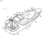
Fig. 1] Fig. 1 is a perspective view of a small watercraft according to an embodiment of the present invention. - [
Fig. 2] Fig. 2 is a perspective view of the small watercraft. - [
Fig. 3] Fig. 3 is a left side view of the small watercraft. - [
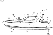
Fig. 4] Fig. 4 is a right side view of the small watercraft. - [
Fig. 5] Fig. 5 is a plan view of the small watercraft. - [
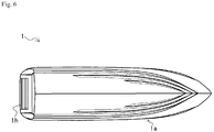
Fig. 6] Fig. 6 is a bottom view of the small watercraft. - [
Fig. 7] Fig. 7 is a front view of the small watercraft. - [
Fig. 8] Fig. 8 is a rear view of the small watercraft. - [
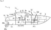
Fig. 9] Fig. 9 is a schematic side view illustrating an internal structure of the small watercraft. - [
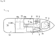
Fig. 10] Fig. 10 is a schematic plan view illustrating an internal structure of the small watercraft. - [
Fig. 11] Fig. 11(a) is a schematic view illustrating a state where a flap door of a rear deck of the small watercraft has turned, andFig. 11 (b) is an enlarged view illustrating another embodiment of the flap door of the rear deck of the small watercraft. - [
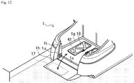
Fig. 12] Fig. 12 is a perspective view illustrating a state where a transom gate of the small watercraft has rotated. - [
Fig. 13] Fig. 13 is a diagram illustrating a pilot house of the small watercraft. - [
Fig. 14] Fig. 14(a) is a perspective view illustrating analog meters of a control panel of the small watercraft, andFig. 14(b) is an enlarged front view of the analog meter of the control panel of the small watercraft. - [
Fig. 15] Fig. 15 is a diagram illustrating an owner room of the small watercraft. - [
Fig. 16] Fig. 16(a) is a perspective view illustrating a structure of a lighting device in the owner room of the small watercraft,Fig. 16(b) is a cross-sectional view illustrating a structure of the lighting device in the owner room of the small watercraft, andFig. 16(c) is a cross-sectional view illustrating a structure of the lighting device including a light distribution plate in the owner room of the small watercraft. - [
Fig. 17] Fig. 17 is a diagram illustrating a salon of the small watercraft. - [
Fig. 18] Fig. 18 is a diagram illustrating a galley of the small watercraft. - [
Fig. 19] Fig. 19 is a diagram illustrating a guest room of the small watercraft. - [
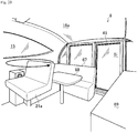
Fig. 20] Fig. 20 is a diagram illustrating a lounge space of the small watercraft. - [
Fig. 21] Fig. 21 is an enlarged perspective view illustrating a state where a movable roof of the small watercraft is open. - [
Fig. 22] Fig. 22 is a diagram illustrating a state where a movable portion of the movable roof of the small watercraft is moving. - [
Fig. 23] Fig. 23 is a perspective view illustrating a stem portion of the small watercraft. - A
small watercraft 1 according to an embodiment of the present invention is described with reference toFigs. 1 to 23 . - As illustrated in
Figs. 1 to 8 , thesmall watercraft 1 is a small watercraft for leisure use, and is used for sports, recreations, and the like. For example, thesmall watercraft 1 has an overall length of approximately 12 m, a weight of approximately 10 tons, and a complement of 12 persons. Thesmall watercraft 1 includes an engine (not illustrated), and is configured to obtain thrust by driving a propeller (not illustrated) with the engine serving as a power source. - As illustrated in
Figs. 1 to 10 , thesmall watercraft 1 includes adeck 1b on an upper side of ahull 1a and acabin 1c on an upper side of thedeck 1b. Thesmall watercraft 1 includes alounge space 8 and apilot house 2 that are in thecabin 1c. Thesmall watercraft 1 has a width of thedeck 1b smaller than a width of thehull 1a, and side portions of thedeck 1b positioned more on the inner side than side portions of thehull 1a. Thehull 1a and thedeck 1b of thesmall watercraft 1 are mainly made of an FRP material. Outer shapes of thehull 1a and thedeck 1b are formed by spraying gelcoat on a mold coated with a release agent (wax), and after the gelcoat is dried (cured), stacking layers of glass fiber roving, unsaturated polyester resin, and the like until a designed thickness is achieved. - Configurations of components of the
small watercraft 1 are described in detail below. - The
hull 1a of thesmall watercraft 1 is provided with thedeck 1b, thecabin 1c, anengine room 1d, aradar arm 1e, a pair of left and rightair introduction ports rear deck 1g, and atransom gate 1h. - The
deck 1b covers an upper part of thehull 1a and forms a compartment and the like. Thedeck 1b is provided with a plurality of windows (afront roof window 11, arear roof window 12, and a pair of left andright side windows 13, 13) for daylighting in the compartment in the inboard section and amooring device 22. - The
front roof window 11 and therear roof window 12 are widows for daylighting in the inboard section. Thefront roof window 11 is disposed at a portion of thedeck 1b more on the front side than thecabin 1c and on a bow side of thedeck 1b, in a non-openable (fixed) state. Thefront roof window 11 is disposed at a portion that is separated from the bow by a distance corresponding to approximately one fifth of the hull length. - The
rear roof window 12 is disposed at a portion of thedeck 1b more on the front side than thecabin 1c and on a stem side of thedeck 1b, in an openable state. Therear roof window 12 is separated from the bow by a distance corresponding to approximately two fifths of the hull length. Therear roof window 12 can be opened by an opening angle that is larger than 90° about a stem side portion. Therear roof window 12 is configured to be tightly closable with a plurality of unillustrated fasteners. Therear roof window 12 in an opened state can be used for ventilating the compartment, for going to and coming back from a bow deck (deck 1b), or for other like purposes. More specifically, an unillustrated ladder supporting unit is formed on a window frame of therear roof window 12. Therear roof window 12 is configured in such a manner that, in the opened state, aladder 100 can be supported by the ladder supporting unit. - The
ladder 100 to be used is configured to be extendable and retractable, and is contained in acontainer box 53 in anowner room 3 described later (seeFig. 15 ). Theladder 100 is configured to be taken out from a side surface opening 53b of thecontainer box 53 to be used. The present embodiment is not limited to theladder 100, and a gangway may be used. - As illustrated in
Figs. 1 to 4 ,9 ,15 ,17 , and18 , theside windows small watercraft 1 are disposed on left and right side portions of thedeck 1b. Theside window 13 is disposed to extend from an approximately center portion in a bow and stem direction to a portion that is separated from the bow by a distance corresponding to one fifth of the hull length. The pair of left andright side windows 13 each have an inboard section side divided into two sections of abow side window 13a and astem side window 13b. The pair of left andright side windows 13 each have thebow side window 13a serving as a window for theowner room 2 and thestem side window 13b serving as a window for asalon 4 and agalley 5. - The
small watercraft 1, divided into the bow side and the stem side at thecabin 1c (pilot house 2), is relatively longer on the bow side. Thus, thesmall watercraft 1 can have a space large enough to dispose thefront roof window 11 and the rear roof window 12 (a space large enough to dispose two roof windows on thedeck 1b arranged in the bow and stem direction). Thus, thesmall watercraft 1 can have the pair of left andright side windows 13 that are large in the bow and stem direction. - As illustrated in
Figs. 1 to 10 , thecabin 1c protrudes beyond thedeck 1b to cover the rear side of thedeck 1b, whereby thepilot house 2 and thelounge space 8 are formed. A person can go into and come out from thecabin 1c through agateway 1c of therear deck 1g. Thecabin 1c includes awindshield 14, a pair of left andright side windows movable roof 16, and awindow door 45 serving as thegateway 1i of therear deck 1g. Thecabin 1c has an opening formed in a roof portion. - As illustrated in
Figs. 1 ,5 ,7 , and13 , thewindshield 14 of thecabin 1c is disposed across left and right end portions of thepilot house 2. - The
windshield 14 has a left and right direction width that is approximately the same as a left and right direction width of thepilot house 2. Thus, thesmall watercraft 1 features a better view from ahelmsman seat 21 a in thepilot house 2 compared with a configuration without thewindshield 14 disposed across the left and right end portions of thepilot house 2. - The
movable roof 16 is provided in the opening formed in the ceiling portion of thecabin 1c. More specifically, themovable roof 16 is disposed above thehelmsman seat 21a and anassistant helmsman seat 21b. As illustrated inFigs. 21 and22 , themovable roof 16 includes a fixedportion 16a and amovable portion 16b, and is openable and closable through sliding movement of themovable portion 16b. The fixedportion 16a and themovable portion 16b of themovable roof 16 are each formed by fitting a glass piece on a frame. Themovable roof 16 hascrosspieces 16c formed in themovable portion 16b to achieve high glass strength. Thus, themovable portion 16b of themovable roof 16 can stably operate. - The
window door 45, serving as thegateway 1i, is provided at a center portion of a stem side end portion of thecabin 1c. Thewindow door 45 is formed as a sliding door that moves in a left-and-right direction to be opened and closed. Thewindow door 45 is entirely glassed. The fixed portions on both left and right sides of thewindow door 45, at the stem side end portion of thecabin 1c, are glassed. - The
small watercraft 1 includes theengine room 1d, theradar arm 1e, the pair of left and rightair introduction ports rear deck 1g, and thetransom gate 1h. - An engine is disposed in the
engine room 1d of thesmall watercraft 1. - The
engine room 1d is provided in a space (inboard section) surrounded by thehull 1a and thedeck 1b. Theengine room 1d is disposed below thecabin 1c. Theengine room 1d is disposed below therear deck 1g. - The
radar arm 1e of thesmall watercraft 1 is provided with a radar (not illustrated) and supports the radar. - The
radar arm 1e is integrally formed with thehull 1a. - The
radar arm 1e is formed to have an arch shape. Theradar arm 1e extends from an upper end from thehull 1a in an inclined manner in an upper rear direction, and surrounds side portions of thedeck 1b, rear side portions of thecabin 1c, and a rear upper portion of thecabin 1c. - The
air introduction ports 1f of thesmall watercraft 1 are used for introducing intake air for the engine into theengine room 1d in the inboard section from the outside. - In the
small watercraft 1, the air introduced into the inboard section through theair introduction ports 1f is supplied to theengine room 1d through piping (not illustrated). - As illustrated in
Fig. 11(a) , therear deck 1g is disposed in a stem portion and more on a rear side than thecabin 1c, and thus therear deck 1g is disposed above theengine room 1d. Anopening 1m, communicating with theengine room 1d, is formed in an approximately center portion of therear deck 1g. Therear deck 1g is provided with aflap door 41 that can be opened and closed to close theopening 1m. In other words, thesmall watercraft 1 has theflap door 41 of therear deck 1g serving as a top board of theengine room 1d. Thus, in thesmall watercraft 1, maintenance work for the engine 23 in theengine room 1d can be performed while theflap door 41 of therear deck 1g is in the open state. - The
flap door 41 can be opened and closed by raising and lowering the bow side of theflap door 41 about ahinge 41a, provided at an end portion on the stem side, serving as a rotational axis. The bow side end portion of theflap door 41 is connected to anelectric cylinder 42 provided in theengine room 1d. Theflap door 41 can be opened and closed through extension and contraction of theelectric cylinder 42. - A trench In is formed at an edge portion over the entire circumference of the
opening 1m on an upper surface of therear deck 1g. The trench In has a shape similar to theflap door 41, and a size large enough to fit theflap door 41 with a gap in between. The trench In is formed to have a depth that is approximately the same as the thickness of theflap door 41. Thus, thetrench 1n supports theflap door 41 in such a manner that the upper surface of therear deck 1g is flush with the upper surface of theflap door 41 covering theopening 1m. As illustrated inFig. 11(b) , thetrench 1n and agroove 1p of therear deck 1g may have bent end portions. - The
transom gate 1h of thesmall watercraft 1 is disposed in the stem side rear end portion. Thetransom gate 1h is formed as a part of a transom surrounding therear deck 1g. - As illustrated in
Fig. 12 , thetransom gate 1h is rotatable. Thetransom gate 1h is used as a path to move from thesmall watercraft 1 to a land (for example, a pier) by being rotated to be laid rearward. - Next, a configuration of an inboard section of the
small watercraft 1 will be described in detail. - As illustrated in
Fig. 9 and10 , thesmall watercraft 1 includes inboard compartments. Thesmall watercraft 1 includes thepilot house 2, theowner room 3, thesalon 4, thegalley 5, aguest room 6, a shower room 7, alounge space 8, and the like. The compartments (thepilot house 2, theowner room 3, thesalon 4, thegalley 5, theguest room 6, the shower room 7, thelounge space 8, and the like) of thesmall watercraft 1 are provided in a space surrounded by thehull 1a, thedeck 1b, and/or thecabin 1c. - The
small watercraft 1 includes thepilot house 2 and thelounge space 8 disposed in thecabin 1c. Thesmall watercraft 1 includes thepilot house 2 disposed on the bow side, and thelounge space 8 disposed on the stem side, in thecabin 1c. Thesmall watercraft 1 has therear deck 1g and thecabin 1c with approximately the same floor (sole) height. Thus, thepilot house 2 is disposed to be a compartment that comes first in the watercraft (thecabin 1c) from thegateway 1i of therear deck 1g. - The
small watercraft 1 has theowner room 3, thesalon 4, thegalley 5, theguest room 6, the shower room 7, and the like at positions that are more on the bow side than thecabin 1c and below the floor of thecabin 1c. Thesmall watercraft 1 has a protrudingportion 2a as a portion of thepilot house 2 on the bow side in thecabin 1c protruding upward to have a space large enough for theowner room 3, thesalon 4, thegalley 5, theguest room 6, the shower room 7, and the like. - As illustrated in
Fig. 9 , steering of thesmall watercraft 1 is performed in thepilot house 2. Thepilot house 2 includes thehelmsman seat 21a, theassistant helmsman seat 21b, and acontrol panel 46. - As illustrated in
Fig. 13 , thepilot house 2 has thehelmsman seat 21a and thecontrol panel 46 on a starboard side relative the bow. Thecontrol panel 46 in thepilot house 2 is provided on a side surface of the protrudingportion 2a in thecabin 1c. Thepilot house 2 has theassistant helmsman seat 21b disposed on a port side relative to the bow. Thepilot house 2 includes apath 1j on the side surface of the protrudingportion 2a in thecabin 1c and at an approximately center portion between thehelmsman seat 21a and theassistant helmsman seat 21b. Thepath 1j extends toward the bow to lead to theowner room 3, thesalon 4, thegalley 5, theguest room 6, the shower room 7, and the like in the inboard section. - A person in charge of steering the
small watercraft 1 sits on thehelmsman seat 21a to perform the steering. Thehelmsman seat 21a is disposed to face thecontrol panel 46. Thehelmsman seat 21a is movable in upper, lower, front, and rear directions to be suitable for the body of the person in charge of steering. - The
control panel 46 includes operation tools, meters, and the like for thesmall watercraft 1 in a concentrated manner. Thecontrol panel 46 is provided withmonitors 47,analog meters 48, ahandle 49, athrottle lever 50, ajoy stick 51, and the like. Thecontrol panel 46 has a plurality of theanalog meters 48 arranged side-by-side in the left and right direction and disposed above themonitors 47. Each of theanalog meters 48 has ametallic ring 48a attached to an edge portion and eightrecesses 48b formed at an equal interval on an outer side surface of thering 48a (seeFig. 14 ). Thecontrol panel 46 has thehandle 49 and thejoy stick 51 disposed on a display screen side of themonitors 47. Thecontrol panel 46 has thethrottle lever 50 disposed on the starboard side. - A person who assists the person in charge of steering the
small watercraft 1 sits on theassistant helmsman seat 21b. Theassistant helmsman seat 21b is arranged side-by-side with thehelmsman seat 21a, and is disposed on the port side. Theassistant helmsman seat 21b is disposed to face a side surface of the protrudingportion 2a in thecabin 1c. Theassistant helmsman seat 21b is disposed on a partially raised floor of thecabin 1c. An air-conditioner outlet 2b is disposed on a portion of the side surface of the protrudingportion 2a in front of theassistant helmsman seat 21b. Askylight 2c, in communication with theguest room 6, is disposed at a portion of an upper surface of the protrudingportion 2a in front of theassistant helmsman seat 21b close to thewindshield 14. A cup holder and the like are disposed on a port side surface close to theassistant helmsman seat 21b. Acabinet 2d is provided on a port side surface behind theassistant helmsman seat 21b. Thecabinet 2d stores a storagetype LCD TV 2e. - As illustrated in
Figs. 9 and10 , theowner room 3 is a main bedroom. Theowner room 3 is more on the bow side than any other one of the compartments. Thus, theowner room 3 is disposed adjacent to a farther side (bow side) of thepath 1j with adoor 3a in between. As illustrated inFig. 15 , abed 52 for two persons is disposed at the center of theowner room 3. Thebed 52 in theowner room 3 includes abed board 52a and abedding 52b such as a mattress. - The
bed 52 in theowner room 3 has thecontainer box 53 on the bed board. Thecontainer box 53 includes a container portion divided into two sections. Thecontainer box 53 includesfloor openings Fig. 15 ) for respective sections on a floor of thebed board 52a and a side surface opening 53b on a side surface of thebed board 52a. Thus, even when thebedding 52b is disposed on thebed board 52a, an object contained in thecontainer box 53 can be taken out through theside surface opening 53b. - The
owner room 3 of thesmall watercraft 1 has curved side surfaces in accordance with the shape of thehull 1a of thesmall watercraft 1. Theowner room 3 hasinner wall materials 54 provided on the inboard section (side portions of the inboard section) in accordance with the shape of the curved side surfaces. An unillustrated audio device and anoperation device 56a for the audio device are provided on a port side surface of theowner room 3 in an embedded manner. Aspeaker 56b is provided on a ceiling of theowner room 3. An air-conditioner outlet 56c that is additional equipment is provided at an upper portion of the side surface of theowner room 3 on the port side. The outlet 56 may be disposed on both starboard and port sides in theowner room 3. Thecabinet 56d is disposed on a rear-starboard side in theowner room 3. - The
bow side windows 13a of theside windows 13 are disposed on side surfaces of theowner room 3 on the starboard and port sides. Thefront roof window 11 is disposed at approximately the center of the ceiling of theowner room 3. Thus, the daylighting in theowner room 3 with sunlight can be achieved through thebow side windows 13a of theside windows 13 formed on thehull 1a and thefront roof window 11 formed on thedeck 1b. - As described above, the
owner room 3 is the compartment that is curved in accordance with the shape of thehull 1a, and has the side surfaces provided with theinner wall materials 54. Thus, in thesmall watercraft 1, the space of the inboard section can be more effectively used, so that theowner room 3 can have a larger space (living space) compared with a configuration in which walls (inner wall materials) stand vertically in the inboard section. The unillustrated audio device and theoperation device 56a for the audio device are embedded in the side surface of theowner room 3. Thus, thesmall watercraft 1 needs no inboard space for placing the audio device and theoperation device 56a for the audio device, whereby the inboard space can be effectively used, so that theowner room 3 can have a larger space (living space). - The
inner wall materials 54 of theowner room 3 of thesmall watercraft 1 include a cushion material. - The
owner room 3 has a plurality of the inner wall materials 54 (cushion materials) that are long in the bow and stem direction arranged in the upper and lower direction in a clinker built fashion. - The
owner room 3 is formed with the plurality ofinner wall materials 54, including the cushion materials, arranged in the upper and lower direction in the clinker built fashion as described above. Thus, in thesmall watercraft 1, the inboard space can be effectively used, so that theowner room 3 can have a larger space (living space). Furthermore, theowner room 3 with a better appearance can be achieved. - The
owner room 3 is formed with a plurality ofbeam members 55 exposed in theowner room 3 in the inboard section (side portions of the inboard section). Theowner room 3 is provided with thebeam members 55 arranged at a predetermined interval in the bow and stem direction in the watercraft. - The
small watercraft 1 with theowner room 3 as a compartment provided with thebeam members 55 exposed in theowner room 3 can have a strength improved with thebeam members 55 exposed in theowner room 3 unlike in the configuration where thebeam members 55 are hidden to make the space of theowner room 3 smaller. - As illustrated in
Figs. 15 and16 , alighting device 57 is disposed at an approximately center portion in the upper and lower direction of each of thebeam members 55 that are disposed to be exposed in theowner room 3 of thesmall watercraft 1. - As illustrated in
Figs. 16(a) and 16(b) , thelighting device 57 is disposed to be embedded in anotch 55a formed at the center portion in the upper and lower direction of thebeam members 55. Thelighting device 57 including alight source 57a such as an incandescent light, a fluorescent light, or an LED lighting device is disposed in a space that is formed to extend toward the inner side of thebeam members 55 from thenotch 55a. Aside surface 55b of thenotch 55a is illuminated with light from thelight source 57a of thelighting device 57. Thus, thelighting device 57 is for indirect lighting using thebeam members 55. As illustrated inFig. 16(c) , thelighting device 57 may be provided with alight distribution plate 57b including a glass plate for dispersing the light in the light radiated directions of the incandescent light, the fluorescent light, or theLED lighting device 57c. - In the
small watercraft 1 with thelighting device 57 disposed in thebeam members 55 in theowner room 3, thelighting device 57 is disposed by using thebeam members 55 exposed in theowner room 3, whereby the number of thelighting device 57 in theowner room 3 can be increased without sacrificing the space in the owner room 3 (compartment). - The
salon 4 illustrated inFig. 9 and10 is what is known as a lounge. Thesalon 4 is disposed on the stem side of theowner room 3 and on the starboard side of thepath 1j. As illustrated inFig. 17 , thesalon 4 includes asofa 58, a table 59, and amonitor 60. Thesalon 4 includes acontainer box 61 disposed below thesofa 58. Thesalon 4 has a ceiling provided with therear roof window 12. Thesalon 4 has thestem side window 13b disposed on a side surface on the starboard side. Daylighting in thesalon 4 with sunlight can be achieved through therear roof window 12 formed in thedeck 1b and thestem side window 13b of theside window 13 formed in thehull 1a. - The
galley 5 illustrated inFig. 9 and10 is what is known as a kitchen. Thegalley 5 is disposed on the stem side of theowner room 3 and on the port side of thepath 1j. Thus, thegalley 5 and thesalon 4 are arranged side-by-side in the left and right direction. As illustrated inFig. 18 , thegalley 5 includes a sink 62, astove 63, astorage shelf 64, and the like. Thegalley 5 has a ceiling provided with therear roof window 12. Thegalley 5 has a side surface on the port side provided with thestem side window 13b of theside window 13. Thus, daylighting in thesalon 4 with sunlight can be achieved through therear roof window 12 formed in thedeck 1b and thestem side window 13b formed in thehull 1a. - The
guest room 6 illustrated inFig. 9 and10 is a second bed room. Theguest room 6 is disposed on the stem side of thegalley 5 and on the port side of thepath 1j. Thus, theguest room 6 is disposed below theassistant helmsman seat 21b in thepilot house 2. As illustrated inFig. 19 , theguest room 6 has a ceiling provided with theskylight 2c. Thus, daylighting of theguest room 6 with sunlight from thewindshield 14 of thecabin 1c can be achieved through theskylight 2c. Theguest room 6 is further provided with an unillustrated reading light. As illustrated inFig. 17 , theguest room 6 includes abed 65 for two persons at the center. Theguest room 6 includes acabinet 66 and adoor 6a disposed on the bow side (a side closer to the galley 5). - As illustrated in
Figs 9 and10 , the shower room 7 is disposed on the stem side of thesalon 4 and on the starboard side of thepath 1j. Thus, the shower room 7 is arranged side-by-side with theguest room 6 with thepath 1j in between, and is disposed below thehelmsman seat 21a in thepilot house 2. - As illustrated in
Fig. 9 , thelounge space 8 of thesmall watercraft 1 is disposed in thecabin 1c at a center portion in the bow and stem direction. Thelounge space 8 is disposed on the stem side in thecabin 1c. Thelounge space 8 is disposed more on the stem side than any other one of the compartments. As illustrated inFig. 20 , thelounge space 8 includes asofa 67, a table 68, and acabinet 69. - As illustrated in any one of
Figs. 1 to 5 ,7 ,9 ,10 , and15 , thesmall watercraft 1 includes theowner room 3 provided with the plurality of windows (thefront roof window 11, therear roof window 12, and the pair of left and rightbow side windows 13a). In thesmall watercraft 1, theowner room 3 can be made bright by daylighting through thefront roof window 11. - The
small watercraft 1 includes theside windows 13, on the side portions of thedeck 1b, having thebow side windows 13a on the left and right sides of theowner room 3 and thestem side windows 13b disposed on thesalon 4 and thegalley 5. Thus, in thesmall watercraft 1, theowner room 3, thesalon 4, and thegalley 5 can be made bright by daylighting through theside windows 13. - In the
small watercraft 1, thesalon 4 and thegalley 5 can be made bright by daylighting through therear roof window 12 and the pair of left and rightstem side windows 13b. Thesmall watercraft 1 has therear roof window 12 that is openable and closable and thus can be used for ventilating the compartments, for going to and coming back from the bow deck (deck 1b), or the like. - As illustrated in any one of
Figs. 1 to 5 ,7 ,9 ,13 , and20 , thesmall watercraft 1 includes thecabin 1c provided with thewindshield 14, the pair of left andright side windows window door 45 serving as thegateway 1i. Thewindshield 14 is disposed at a front portion of thecabin 1c and theside windows cabin 1c. Thewindshield 14 is disposed on the front side of thehelmsman seat 21a, and theside windows helmsman seat 21 a. Thecabin 1c of thesmall watercraft 1 is provided with the glassedwindow door 45, serving as thegateway 1i to therear deck 1g, on the stem side. Thewindow door 45 is disposed at the stem side end portion of thecabin 1c and serves as a partition from therear deck 1g. - The
small watercraft 1 includes thepilot house 2 and thelounge space 8 that are surrounded by thewindshield 14, the pair of left andright side windows movable roof 16, and thewindow door 45. Thus, in thesmall watercraft 1, thehelmsman seat 21 a and thelounge space 8 can be made bright by daylighting through thewindshield 14, the pair of left andright side windows 15, themovable roof 16, and thewindow door 45. Furthermore, theguest room 6 can be made bright by the daylighting through theskylight 2c. - As illustrated in any one of
Figs. 9 ,13 , and20 , thepilot house 2 and thelounge space 8 of thesmall watercraft 1 are disposed in the same space with no partitioning wall separating one from the other provided in between. Thehelmsman seat 21a in thepilot house 2 is movable in the upper, lower, front, and rear directions. Thehelmsman seat 21a in thepilot house 2 is rotatable by 360° to adjust the orientation (the orientation of the driver in charge of steering sitting on thehelmsman seat 21a). In thesmall watercraft 1, thehelmsman seat 21 a is oriented toward the bow side when the steering of thesmall watercraft 1 is performed. Thehelmsman seat 21 a in thepilot house 2 rotated to be oriented to the lounge space 8 (for example, rotated by 180° from the bow side) faces thesofa 67 and the table 68 in thelounge space 8. - In the
small watercraft 1 in which thepilot house 2 and thelounge space 8 are disposed in the same space and thehelmsman seat 21a in thepilot house 2 rotated to be oriented toward thelounge space 8 faces thesofa 67 and the table 68 in thelounge space 8 as described above, thehelmsman seat 21 a in thepilot house 2 rotated to be oriented toward thelounge space 8 faces thesofa 67 and the table 68 in thelounge space 8, and thus the table 68 in thelounge space 8 can be surrounded by thehelmsman seat 21a in thepilot house 2 and thesofa 67 in thelounge space 8. - Thus, the
pilot house 2 and thelounge space 8 can each have a compact structure in thesmall watercraft 1 without compromising the functionality, whereby the space in which thepilot house 2 and thelounge space 8 are formed can be effectively used. - The
pilot house 2 of thesmall watercraft 1 further includes theassistant helmsman seat 21b that is disposed next to (on the left side of) thehelmsman seat 21a, movable in the upper, lower, front and rear directions as in the case of thehelmsman seat 21a, and rotatable by 360°. - The
assistant helmsman seat 21b in thepilot house 2 rotated to be oriented toward thelounge space 8 faces thesofa 67 and the table 68 in thelounge space 8. - As described above, the seats in the
pilot house 2, that is, theassistant helmsman seat 21b and thehelmsman seat 21a in thepilot house 2 rotated to be oriented toward thelounge space 8 face thesofa 67 and the table 68 in thelounge space 8. Thus, in thesmall watercraft 1, the table 68 in thelounge space 8 can be surrounded by thehelmsman seat 21a and theassistant helmsman seat 21b in thepilot house 2, and thesofa 67 in thelounge space 8. - As illustrated in
Figs. 1 to 10 , thesmall watercraft 1 is relatively long on the bow side as viewed from thepilot house 2. - Thus, the
small watercraft 1 can have a space large enough to dispose thefront roof window 11 and the rear roof window 12 (space large enough to arrange the two roof windows on thedeck 1b in the bow and stem direction). - In addition, the pair of left and
right side windows 13 of thesmall watercraft 1 can be made large in the bow and stem direction. - Furthermore, the
owner room 3, theguest room 6, thesalon 4, thegalley 5, and the shower room 7 of thesmall watercraft 1 can be made wide in the bow and stem direction. - As illustrated in
Fig. 23 , thesmall watercraft 1 may include aseat 19 and abackrest 20 in the stem portion. Theseat 19 in thesmall watercraft 1 is detachably attached to therear deck 1g and thebackrest 20 is detachably attached to an inner wall of the transom. - The present invention can be applied to a technique for a small watercraft for leisure use that is used for sports, recreations, and the like.
-
- 1
- small watercraft
- 1a
- hull
- 1b
- deck
- 1c
- cabin
- 1d
- engine room
- 1e
- radar arm
- 1f
- air introduction port
- 1g
- rear deck
- 1i
- gateway
- 1j
- path
- 2
- pilot house
- 3
- owner room
- 4
- salon
- 5
- galley
- 6
- guest room
- 7
- shower room
- 8
- lounge space
- 11
- front roof window
- 12
- rear roof window
- 13
- side window
- 14
- windshield
- 15
- side windows
- 16
- movable roof
- 54
- inner wall material
- 55
- beam member
Claims (4)
- A small watercraft for leisure use comprising a compartment,
wherein the compartment is formed with an inner wall material provided on an inboard section in such a manner as to be curved in accordance with a shape of the inboard section. - The small watercraft according to claim 1,
wherein the compartment includes a beam member exposed in the compartment. - The small watercraft according to claim 2,
wherein the compartment includes a lighting device disposed to the beam member. - The small watercraft according to any one of claims 1 to 3, further comprising:a pilot house; anda windshield disposed on a front side of the pilot house, whereinthe windshield is disposed across left and right end portions of the pilot house.
Applications Claiming Priority (4)
| Application Number | Priority Date | Filing Date | Title |
|---|---|---|---|
| JP2013154038 | 2013-07-24 | ||
| JP2013257527A JP2015024804A (en) | 2013-12-12 | 2013-12-12 | Small ship |
| JP2013257528A JP2015042541A (en) | 2013-07-24 | 2013-12-12 | Small boat |
| PCT/JP2014/069070 WO2015012197A1 (en) | 2013-07-24 | 2014-07-17 | Small watercraft for leisure use |
Publications (2)
| Publication Number | Publication Date |
|---|---|
| EP3025950A1 true EP3025950A1 (en) | 2016-06-01 |
| EP3025950A4 EP3025950A4 (en) | 2017-03-15 |
Family
ID=55472871
Family Applications (1)
| Application Number | Title | Priority Date | Filing Date |
|---|---|---|---|
| EP14829853.2A Withdrawn EP3025950A4 (en) | 2013-07-24 | 2014-07-17 | Small watercraft for leisure use |
Country Status (5)
| Country | Link |
|---|---|
| US (1) | US20160159441A1 (en) |
| EP (1) | EP3025950A4 (en) |
| CN (1) | CN105408198A (en) |
| AU (1) | AU2014294186A1 (en) |
| WO (1) | WO2015012197A1 (en) |
Family Cites Families (13)
| Publication number | Priority date | Publication date | Assignee | Title |
|---|---|---|---|---|
| US1848502A (en) * | 1932-03-08 | Haeold l | ||
| US4064584A (en) * | 1976-09-13 | 1977-12-27 | James Harold Funkhouser | Upper boat deck |
| JPS54115888A (en) * | 1978-02-27 | 1979-09-08 | Yamaha Motor Co Ltd | Ceiling structure in cabin of small ship |
| GB2050256A (en) * | 1979-05-29 | 1981-01-07 | Aston H C A | Improvements in and relating to the construction of boat hulls |
| SE456331B (en) * | 1985-04-26 | 1988-09-26 | Acci Handelsbolag | ROOM UNIT, SPECIFICALLY CABIN OR COTTAGE BY VESSEL |
| JPH0798508B2 (en) * | 1985-05-01 | 1995-10-25 | ヤマハ発動機株式会社 | Small hull structure |
| JP2906132B2 (en) * | 1996-04-03 | 1999-06-14 | ミヤマ造船株式会社 | Ship |
| FR2771994B1 (en) * | 1997-12-04 | 2000-01-14 | Dufour And Sparks Sa | CRAFT FOR HOUSEHOLD USE |
| JP2000163605A (en) * | 1998-11-30 | 2000-06-16 | Yanmar Diesel Engine Co Ltd | 3D shape drawing method |
| JP5044449B2 (en) | 2008-03-05 | 2012-10-10 | ヤマハ発動機株式会社 | Small ship |
| CN101767631A (en) * | 2008-12-29 | 2010-07-07 | 上海红双喜游艇有限公司 | Glass reinforced plastic module connecting method for yacht |
| IT1394863B1 (en) * | 2009-07-22 | 2012-07-20 | Fb Design Srl | QUICK METHOD FOR THE CONSTRUCTION OF BOATS |
| US8337265B2 (en) * | 2009-07-24 | 2012-12-25 | Neprud Kevin R | Amphibious yacht |
-
2014
- 2014-07-17 AU AU2014294186A patent/AU2014294186A1/en not_active Abandoned
- 2014-07-17 CN CN201480041839.8A patent/CN105408198A/en active Pending
- 2014-07-17 WO PCT/JP2014/069070 patent/WO2015012197A1/en not_active Ceased
- 2014-07-17 US US14/905,909 patent/US20160159441A1/en not_active Abandoned
- 2014-07-17 EP EP14829853.2A patent/EP3025950A4/en not_active Withdrawn
Also Published As
| Publication number | Publication date |
|---|---|
| AU2014294186A1 (en) | 2016-03-10 |
| EP3025950A4 (en) | 2017-03-15 |
| CN105408198A (en) | 2016-03-16 |
| WO2015012197A1 (en) | 2015-01-29 |
| US20160159441A1 (en) | 2016-06-09 |
Similar Documents
| Publication | Publication Date | Title |
|---|---|---|
| US9079528B2 (en) | PSU pod assembly and method for using same | |
| US9365291B2 (en) | Passenger service unit pod assembly | |
| US20170349244A1 (en) | Cuddy cabin vessel with separate privacy enclosure | |
| US20060237585A1 (en) | Airplane interior systems | |
| US8616143B2 (en) | Boat access hatch and seat | |
| CN109803889A (en) | Seat arrangement, in particular for an aircraft | |
| CA2807530A1 (en) | Integrated aircraft interior | |
| CN105408201B (en) | Leisure spitkit | |
| US6860222B2 (en) | Convertible deck yacht | |
| CN106715266A (en) | Overhead luggage compartment for aircraft | |
| US9522735B2 (en) | Aircraft area comprising a luggage compartment | |
| US20210261255A1 (en) | Aircraft Interior Structure Including a Surface and an Integrated Footwell | |
| CN205770000U (en) | A kind of hatch board with concealed hand steered device | |
| JP2015042541A (en) | Small boat | |
| US20160159441A1 (en) | Small watercraft for leisure use | |
| CN109383809B (en) | Aircraft with a flight control device | |
| US7401568B2 (en) | Boat with skylight windows | |
| JP5086994B2 (en) | Renovation of aircraft cabin seats and baggage compartment | |
| JP2015024804A (en) | Small ship | |
| JP2017119481A (en) | Liquefied gas carrier | |
| JP7720794B2 (en) | Floating body | |
| JP2015024803A (en) | Small ship | |
| CA2755146A1 (en) | Family boat | |
| Plan | port | |
| US20140331907A1 (en) | Marine aft bulkhead and window system |
Legal Events
| Date | Code | Title | Description |
|---|---|---|---|
| PUAI | Public reference made under article 153(3) epc to a published international application that has entered the european phase |
Free format text: ORIGINAL CODE: 0009012 |
|
| 17P | Request for examination filed |
Effective date: 20160224 |
|
| AK | Designated contracting states |
Kind code of ref document: A1 Designated state(s): AL AT BE BG CH CY CZ DE DK EE ES FI FR GB GR HR HU IE IS IT LI LT LU LV MC MK MT NL NO PL PT RO RS SE SI SK SM TR |
|
| AX | Request for extension of the european patent |
Extension state: BA ME |
|
| DAX | Request for extension of the european patent (deleted) | ||
| A4 | Supplementary search report drawn up and despatched |
Effective date: 20170210 |
|
| RIC1 | Information provided on ipc code assigned before grant |
Ipc: B63B 19/00 20060101ALI20170206BHEP Ipc: B63B 3/26 20060101ALI20170206BHEP Ipc: B63B 29/02 20060101ALI20170206BHEP Ipc: B63B 45/06 20060101ALI20170206BHEP Ipc: B63B 11/00 20060101AFI20170206BHEP |
|
| STAA | Information on the status of an ep patent application or granted ep patent |
Free format text: STATUS: REQUEST FOR EXAMINATION WAS MADE |
|
| STAA | Information on the status of an ep patent application or granted ep patent |
Free format text: STATUS: THE APPLICATION IS DEEMED TO BE WITHDRAWN |
|
| 18D | Application deemed to be withdrawn |
Effective date: 20170912 |