EP3025882A1 - Amphibious unicycle - Google Patents
Amphibious unicycle Download PDFInfo
- Publication number
- EP3025882A1 EP3025882A1 EP13890232.5A EP13890232A EP3025882A1 EP 3025882 A1 EP3025882 A1 EP 3025882A1 EP 13890232 A EP13890232 A EP 13890232A EP 3025882 A1 EP3025882 A1 EP 3025882A1
- Authority
- EP
- European Patent Office
- Prior art keywords
- annular casing
- unicycle
- accommodation cavity
- seat
- amphibious
- Prior art date
- Legal status (The legal status is an assumption and is not a legal conclusion. Google has not performed a legal analysis and makes no representation as to the accuracy of the status listed.)
- Granted
Links
- 230000004308 accommodation Effects 0.000 claims abstract description 45
- 238000007789 sealing Methods 0.000 claims description 5
- XLYOFNOQVPJJNP-UHFFFAOYSA-N water Substances O XLYOFNOQVPJJNP-UHFFFAOYSA-N 0.000 abstract description 15
- QVGXLLKOCUKJST-UHFFFAOYSA-N atomic oxygen Chemical compound [O] QVGXLLKOCUKJST-UHFFFAOYSA-N 0.000 description 5
- 229910052760 oxygen Inorganic materials 0.000 description 5
- 239000001301 oxygen Substances 0.000 description 5
- 238000005516 engineering process Methods 0.000 description 2
- 239000004576 sand Substances 0.000 description 2
- 230000008859 change Effects 0.000 description 1
- 230000009189 diving Effects 0.000 description 1
- 230000035622 drinking Effects 0.000 description 1
- 239000000428 dust Substances 0.000 description 1
- 239000003292 glue Substances 0.000 description 1
- 238000005286 illumination Methods 0.000 description 1
- 230000007246 mechanism Effects 0.000 description 1
- 238000000034 method Methods 0.000 description 1
- 230000004048 modification Effects 0.000 description 1
- 238000012986 modification Methods 0.000 description 1
- 230000008569 process Effects 0.000 description 1
- 239000007921 spray Substances 0.000 description 1
Images


Classifications
-
- B—PERFORMING OPERATIONS; TRANSPORTING
- B60—VEHICLES IN GENERAL
- B60F—VEHICLES FOR USE BOTH ON RAIL AND ON ROAD; AMPHIBIOUS OR LIKE VEHICLES; CONVERTIBLE VEHICLES
- B60F3/00—Amphibious vehicles, i.e. vehicles capable of travelling both on land and on water; Land vehicles capable of travelling under water
- B60F3/0061—Amphibious vehicles specially adapted for particular purposes or of a particular type
- B60F3/0084—Amphibious cycles
-
- B—PERFORMING OPERATIONS; TRANSPORTING
- B63—SHIPS OR OTHER WATERBORNE VESSELS; RELATED EQUIPMENT
- B63H—MARINE PROPULSION OR STEERING
- B63H5/00—Arrangements on vessels of propulsion elements directly acting on water
- B63H5/02—Arrangements on vessels of propulsion elements directly acting on water of paddle wheels, e.g. of stern wheels
-
- B—PERFORMING OPERATIONS; TRANSPORTING
- B63—SHIPS OR OTHER WATERBORNE VESSELS; RELATED EQUIPMENT
- B63H—MARINE PROPULSION OR STEERING
- B63H5/00—Arrangements on vessels of propulsion elements directly acting on water
- B63H5/07—Arrangements on vessels of propulsion elements directly acting on water of propellers
Definitions
- the application relates to the field of vehicle technology, especially to an amphibious unicycle.
- the basic structures of vehicles still keep the multiple-wheel-drive mode. Furthermore, at present, the vehicles can only drive on flat lands. For vehicles which need to meet the requirements for driving in deserts or other special lands, additional reformations to the structures of the vehicle are required so as to adapt to different ground conditions. Furthermore, at present, only hydrogliders can drive on the surface of water; the hydrogliders are not driven by wheels to drive on the surface of water, but belong to one type of airplanes. Only submarines can dive in the water, and there is no vehicle capable of diving in the water now.
- the vehicles in the prior art possess poor adaptability of driving conditions, and do not have the ability to drive underwater or on the water surface, that is, the vehicles in the prior art have no amphibious function.
- the application aims at providing an amphibious unicycle, and solving the problems that the vehicles in the prior art possess poor adaptability on driving conditions and have no amphibious function.
- the invention is realized by an amphibious unicycle which comprises an annular casing having a accommodation cavity; two sides of the annular casing are respectively provided with two openings which are communicated with the accommodation cavity; doors are arranged at the openings for sealing the openings; the doors are rotatably connected with the annular casing; two sides of the annular casing are respectively provided with external rotor motors arranged annularly; the external rotors of the external rotor motors are provided with a plurality of drainage holes arranged around the periphery of the external rotors; the accommodation cavity is provided therein with a power system for driving the unicycle.
- the unicycle provided by the invention can form a enclosed structure comprising the door and the annular casing; owing to the external rotor motors at two sides of the annular casing and the external rotors, the unicycle can drive on lands including the desert, and even on the surface of water; the unicycle possesses great adaptability to driving conditions and amphibious effect.
- the embodiment provides an amphibious unicycle 1, which comprises an annular casing 100; the annular casing 100 is provided with an accommodation cavity 1001. Two openings are arranged on the two sides of the annular casing 100 respectively; the two openings are communicated with the accommodation cavity 1001. Doors 101 are hermetically arranged on the openings on two sides of the annular casings 100. The doors 101 are rotatably connected to the annular casing 100. When the doors 101 are closed, the doors 101 seal the accommodation cavity 1001; when the doors 101 are opened, the accommodation cavity 1001 is in an opening state.
- the annular casing 100 can also be provided with an opening on one side thereof, therefore, it is possible to provide only one aforesaid door 101 .
- the opening can also be arranged on other positions of the annular casing 100 such as the upper end or the lower end. Therefore, when the door 101 is arranged on the opening, the door 101 can also seal the accommodation cavity 1001 of the annular casing 100.
- the annular casing 100 can be set into other shapes such as square or other different shapes, which is not limited by this embodiment, as long as the annular casing 100 is a casing having the accommodation cavity 1001, and provided with the opening; the opening is provided with a door 101 which can seal the accommodation cavity 1001, and the door 101 is rotatably connected with the casing.
- the external rotor motors comprise external rotors 111 which are arranged vertically along both sides of the annular casing 100; furthermore, the external rotors 111 are provided with a plurality of drainage holes 1111 distributed around the peripheries of the external rotors 111.
- the two sides of annular casing 100 is further provided with drive gear structures 1112 arranged annularly and propellers 119; the propellers 119 are driven by the drive gear structures 1112 to rotate.
- the drive gear structures 1112 are arranged on the inner sides of the external rotors 111, and the propellers 119 are extended beyond the annular casing 100.
- each of the above mentioned drive gear structures 1112 comprises gears arranged around the inner sides of the external rotors 111 and a rotor for driving the rotation.
- the power element for driving the rotation of gears can also be an air cylinder.
- the gears are propeller gears; surely, the gears can also be gears of other structures.
- the propeller 119 comprises a propeller stem; a gearhead is arranged at the upper end of the propeller stem, and the gearhead is configured to engage with the gears of the drive gear structure 1112.
- a plurality of paddles are arranged at the lower end of the propeller stem, and the plurality of paddles are distributed annularly.
- the gearhead of the propeller 119 of the drive gear structure 1112 rotates so as to rotate the propeller stem, and further drive the plurality of paddles to rotate, thereby providing power to drive the unicycle 1 forward.
- the above mentioned two external rotors 111 in combination of the annular casing 100 constitute a structure of a single-wheel shape.
- the accommodation cavity 1001 of the above mentioned annular casing 100 is further provided therein with a power system113, which is configured to drive the whole unicycle 1 to run and provide power.
- the power system 113 is electrically connected with the above mentioned drive gear structures 1112. Therefore, the power system 113 drives the motors to run, thereby making the gears drive the external rotors 111 work, and enable the unicycle 1 to run.
- the unicycle 1 provided by the embodiment can drive on lands using the external rotors 111 arranged on two sides of the annular casing 100.
- the annular casing 100 and the doors 101 can form an enclosed structure, which means that the doors 101 seals the openings of the annular casing 100 so as to make the accommodation cavity 1001 be enclosed. Therefore, through the enclosed structure constituted by the annular casing 100 and the doors 101, and the drainage holes 1111 of the external rotors 111, which function as propellers during running, water can be pushed so that the unicycle 1 can drive on the surface of water.
- the unicycle 1 can dive into water by adjusting the weight of the unicycle 1 and keeping the unicycle 1 in the enclosed state; the drive gear structures 1112 drive the propellers 119 to rotate, thereby driving the unicycle 1 to travel in the water. Furthermore, owing to the structure of the drainage holes 1111 of the external rotors 111, the unicycle 1 can also drive in the desert.
- the drainage holes 1111 makes the unicycle 1 drive in the desert fast by pushing the sand, and in the driving process, the sand can be discharged through the drainage holes 1111. Therefore, the unicycle 1 provided by the embodiment possesses the functions of driving on flat lands, in the desert, on the surface of water and into the water, thereby achieving great adaptability on drive conditions and amphibious effect.
- the lower end of the annular casing 100 is flat and has relatively large spacing with the lower ends of the external rotors 111 so as to protect the lower end of the unicycle 1 from colliding with the land during driving, meanwhile, the unicycle 1 is enabled to adapt to rugged lands.
- the upper end, front end, and rear end of the annular casing 100 are protruded and extended beyond the external rotors 111. Therefore, the dimension of the accommodation cavity 1001 of the annular casing 100 is increased greatly, and the accommodation of the unicycle 1 is bigger and has larger space.
- the external rotors 111 are provided with a brake 104, by which the external rotors 111 are braked, thereby decelerating or stopping the unicycle 1, or keeping the unicycle 1 in stop state.
- each of the external rotors 111 is provided with an elastic ring which can protect the external rotors 111.
- each opening of the annular casing 100 is round; the opening can be other shapes for sure.
- the periphery of each door 101 is provided with sealing glue , which renders better connection and a higher sealing degree between the door 101 and the sidewall of the opening of the annular casing 100.
- both the inner side and the external side of each door 101 are provided with locks; the locks can lock the door 101 with the annular casing 100 together so as to protect the door 101 from opening when the unicycle 1 is driving, thereby ensuring the safety of the driver.
- the accommodation cavity 1001 of the annular casing 100 is provided therein with an extendable stick; two ends of the extendable stick extend toward the openings of the annular casing 100 and are connected to an inner side of the door 101 respectively.
- the door 101 is connected with the annular casing 100 through a spindle; therefore, the door 101 can rotate relative to the annular casing 100.
- the extendable stick is arranged to be deviated from the spindle; therefore, owing to the concertina movement of the extendable stick, the door 101 can rotate relative to the annular casing 100, thereby realizing the effect of opening or closing the accommodation cavity 1001.
- the extendable stick can be omitted, and then the door 101 can be rotated manually so as to open or close the accommodation cavity 1001.
- the lower end of above mentioned annular casing 100 is further provided with a protruding support 102 which is connected to the lower end of the annular casing 100, extended forward, and then bent upward to form a bumper 1021.
- the bumper 1021 is arranged in front of the annular casing 100, and two sides of the bumper 1021 are provided with turn lights 1022 respectively. When the unicycle 1 needs to be rotated, the turn lights 1022 can be operated directly for safe drive, and the turn lights 1022 possess the effect of front lighting.
- the bumper 1021 is provided with a sprayer structure and a wiper blade 1024.
- the bumper 1021 can spray towards the annular casing 100.
- the wiper blade 1024 can wipe the surface of the annular casing 100 so as to wipe out the dust, rainwater or others on the annular casing 100.
- the rearview mirrors 115 can not only function as rearview mirrors when the unicycle 1 is driving, but also function as navigation elements.
- the annular casing 100 is provided with at least one venthole 1002 with open-close function.
- the venhole 1002 is communicated with the accommodation cavity 1001 of the annular casing 100. Therefore, when the unicycle 1 does not drive underwater, the venthole 1002 can be opened to communicate the accommodation cavity 1001 with exterior for ventilating. When the unicycle 1 drives underwater, the venthole 1002 should be closed to seal the accommodation cavity 1001 of the annular casing 100.
- the annular casing 100 is further provided with a strip-shape support 103.
- the upper end of the support 103 is rotatably connected to the annular casing 100; therefore, the support 103 can wiggle relative to the annular casing 100 so as to abut the lower end of the support 103 against the ground. Therefore, staff such as the driver can reach the roof of the annular casing 100 through the support 103 to maintain and operate or implement other operations.
- the lower end of the support 103 is provided with an anti-skid wheel 1032.
- the anti-skid wheel 1032 can prevent the lower end of the support 103 from skidding so as to ensure the safety of the staff.
- the lower end of the support 103 can be provided with other anti-skid mechanisms that are not limited to the anti-skid wheel 1032, such as anti-skid mat.
- the above mentioned support 103 is further provided with a fog-proof light 1031 which is arranged towards opposite to the surface of the annular casing 100. Therefore, if there is frog in front when the unicycle 1 is driving, the frog-proof light 1031 can be turned on to ensure the safety of the driving unicycle 1.
- the propeller stem of the propeller 119 is connected with the support 103, therefore, when the unicycle 1 needs to dive into the water, the support 103 can be wiggled to an appropriate position.
- the gearhead of the propeller 119 will engage with the drive gear structure 1112.
- the plurality of paddles of the propeller stem will extend outwards the annular casing 100, and the drive gear structure 1112 drives the propeller 119 to rotate.
- the accommodation cavity 1001 of the annular casing 100 is provided with a first seat 110 inside the accommodation cavity 1001 so that the driver can sit in the unicycle 1 during driving.
- the first seat 110 features the back door function, and a side of the first seat 110 is provided with a door handle 107 for controlling the opening or closing of the door 101.
- the first seat 110 can be a back-rest chair which can support the back or other types of chairs for sure. Both sides of the first seat 110 are provided with handrails for the driver to hold when he/she stands up.
- a second seat 114 is arranged in front of the first seat 110; the second seat 114 and the first seat 110 are arranged to space from each other, therefore, the accommodation cavity 1001 of the annular casing 100 can accommodate two persons.
- the second seat 114 is provided with a safety belt 109, and a headrest 108 is arranged at the upper end of the second seat 114.
- An intercommunication device 1083 is embedded in the headrest 108, which can ensure that the driver can communicate with the exterior.
- the headrest 108 is further provided with a reading lamp 1082.
- the reading lamp 1082 When the reading lamp 1082 is turned on, the driver can read, write, or implement other operations in the accommodation cavity 1001.
- the end surface of the second seat 114 towards the first seat 110 is provided with a bag for books and newspaper. A plurality of magazines, notebooks or others can be placed in the bag for the driver to read, take notes, or perform implement other operations.
- the power system 113 is a power battery which is located under the first seat 110 and the second seat 114. To be sure, the power system 113 can be in other types, and should not be restricted to the power battery of the embodiment.
- the accommodation cavity 1001 is further provided therein with an oxygen bottle 105.
- the oxygen bottle 105 can provide oxygen to the driver for breath so as to ensure the safety of the driver.
- the oxygen bottle 105 can be located at many locations. In the embodiment, the oxygen bottle 105 is located at the backside of the first seat 110.
- the backside of the first seat 110 is further provided with a cup holder 106 configured to hold cup or others for daily drinking of the driver.
- the cup holder 106 can be arranged at other locations according to actual requirements.
- the accommodation cavity 1001 of the annular casing 100 is provided therein with a heat pump air conditioner with open-close function; correspondingly, the annular casing 100 is provided with an exhaust vent. Therefore, when the heat pump air conditioner is working, air can be exhausted through the exhaust vent.
- an inlet vent is arranged at the lower end of the annular casing 100.
- the inlet vent cooperates with the exhaust vent to realize the entrance and discharge of air.
- the accommodation cavity 1001 is further provided with a headlight 1031 and a tail light 116.
- the headlight 1031 can be located in front of the accommodation cavity 1001 or outside of the accommodation cavity 1001, i.e., at the protruding support 12 for sure.
- the rear light 116 is located in the rear of the accommodation cavity 1001.
- a clamping piece 108 is arranged at the end surface of the headrest 108 towards the first seat 110, and the clamping piece 108 is used to clamp common devices such as a computer.
- the accommodation cavity 1001 is provided with a trunk which is located behind the first seat 110.
- the amphibious unicycle 1 provided by the embodiment is a pure electrombile based on a motor with multipolar-distributed-drive switch reluctance external rotor 111.
- the amphibious unicycle 1 can drive in deserts and on other lands, navigate on the surface of water, and underwater up to 2 meters when equipped with a dive bag. Its highest speed record on the land can reach 100 km/h holding 2 persons.
- the dead weight of the amphibious unicycle 1 can be 350Kg, and full load thereof can be 500Kg; if a 18.6KWH battery package thereof is fully charged, the amphibious unicycle 1 can travel about 600Km.
- the amphibious unicycle 1 is applicable widely to urban traffic, regional transport, military landing, tourist site stroll, field observation, and implementations of business and mission.
Abstract
Description
- The application relates to the field of vehicle technology, especially to an amphibious unicycle.
- With the development of technology, vehicles are more and more diversified, and structures of vehicles change accordingly.
- In the prior art, the basic structures of vehicles still keep the multiple-wheel-drive mode. Furthermore, at present, the vehicles can only drive on flat lands. For vehicles which need to meet the requirements for driving in deserts or other special lands, additional reformations to the structures of the vehicle are required so as to adapt to different ground conditions. Furthermore, at present, only hydrogliders can drive on the surface of water; the hydrogliders are not driven by wheels to drive on the surface of water, but belong to one type of airplanes. Only submarines can dive in the water, and there is no vehicle capable of diving in the water now.
- Above all, the vehicles in the prior art possess poor adaptability of driving conditions, and do not have the ability to drive underwater or on the water surface, that is, the vehicles in the prior art have no amphibious function.
- The application aims at providing an amphibious unicycle, and solving the problems that the vehicles in the prior art possess poor adaptability on driving conditions and have no amphibious function.
- The invention is realized by an amphibious unicycle which comprises an annular casing having a accommodation cavity; two sides of the annular casing are respectively provided with two openings which are communicated with the accommodation cavity; doors are arranged at the openings for sealing the openings; the doors are rotatably connected with the annular casing; two sides of the annular casing are respectively provided with external rotor motors arranged annularly; the external rotors of the external rotor motors are provided with a plurality of drainage holes arranged around the periphery of the external rotors; the accommodation cavity is provided therein with a power system for driving the unicycle.
- Compared with the prior art, the unicycle provided by the invention can form a enclosed structure comprising the door and the annular casing; owing to the external rotor motors at two sides of the annular casing and the external rotors, the unicycle can drive on lands including the desert, and even on the surface of water; the unicycle possesses great adaptability to driving conditions and amphibious effect.
-
-
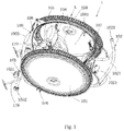
Fig. 1 is a perspective schematic view of an amphibious unicycle provided by an embodiment of the invention; -
Fig. 2 is an enlarged schematic view of the part A ofFig. 1 ; -
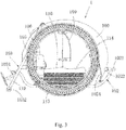
Fig. 3 is a left schematic view of an amphibious unicycle provided by an embodiment of the invention; -
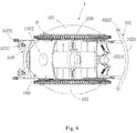
Fig. 4 is a sectional schematic view of an amphibious unicycle provided by an embodiment of the invention; -
Fig. 5 is a front schematic view of an amphibious unicycle provided by an embodiment of the invention; -
Fig. 6 is a top schematic view of an amphibious unicycle provided by an embodiment of the invention; and -
Fig. 7 is an enlarged schematic view of the part B ofFig. 6 . - The invention will be further described in detail accompanying with the embodiments and drawings in order to make the purpose, technical solutions and advantages of the invention more clear. It should be understood that the specific embodiments described herein are just for explanation and should not deemed as limitation to the invention.
- The invention will be described in detail accompanying with the specific drawings.
- As shown in
Figs. 1-7 , a preferred embodiment of the invention is provided. - The embodiment provides an
amphibious unicycle 1, which comprises anannular casing 100; theannular casing 100 is provided with anaccommodation cavity 1001. Two openings are arranged on the two sides of theannular casing 100 respectively; the two openings are communicated with theaccommodation cavity 1001.Doors 101 are hermetically arranged on the openings on two sides of theannular casings 100. Thedoors 101 are rotatably connected to theannular casing 100. When thedoors 101 are closed, thedoors 101 seal theaccommodation cavity 1001; when thedoors 101 are opened, theaccommodation cavity 1001 is in an opening state. - To be sure, in other embodiments, the
annular casing 100 can also be provided with an opening on one side thereof, therefore, it is possible to provide only oneaforesaid door 101 . Alternatively, the opening can also be arranged on other positions of theannular casing 100 such as the upper end or the lower end. Therefore, when thedoor 101 is arranged on the opening, thedoor 101 can also seal theaccommodation cavity 1001 of theannular casing 100. - Alternatively, the
annular casing 100 can be set into other shapes such as square or other different shapes, which is not limited by this embodiment, as long as theannular casing 100 is a casing having theaccommodation cavity 1001, and provided with the opening; the opening is provided with adoor 101 which can seal theaccommodation cavity 1001, and thedoor 101 is rotatably connected with the casing. - In the embodiment, two sides of the
annular casing 100 are provided with external rotor motors respectively; the external rotor motors compriseexternal rotors 111 which are arranged vertically along both sides of theannular casing 100; furthermore, theexternal rotors 111 are provided with a plurality ofdrainage holes 1111 distributed around the peripheries of theexternal rotors 111. - The two sides of
annular casing 100 is further provided withdrive gear structures 1112 arranged annularly andpropellers 119; thepropellers 119 are driven by thedrive gear structures 1112 to rotate. Thedrive gear structures 1112 are arranged on the inner sides of theexternal rotors 111, and thepropellers 119 are extended beyond theannular casing 100. - Specifically, each of the above mentioned
drive gear structures 1112 comprises gears arranged around the inner sides of theexternal rotors 111 and a rotor for driving the rotation. To be sure, the power element for driving the rotation of gears can also be an air cylinder. In the embodiment, the gears are propeller gears; surely, the gears can also be gears of other structures. Thepropeller 119 comprises a propeller stem; a gearhead is arranged at the upper end of the propeller stem, and the gearhead is configured to engage with the gears of thedrive gear structure 1112. A plurality of paddles are arranged at the lower end of the propeller stem, and the plurality of paddles are distributed annularly. The gearhead of thepropeller 119 of thedrive gear structure 1112 rotates so as to rotate the propeller stem, and further drive the plurality of paddles to rotate, thereby providing power to drive theunicycle 1 forward. - Hence, the above mentioned two
external rotors 111 in combination of theannular casing 100 constitute a structure of a single-wheel shape. - The
accommodation cavity 1001 of the above mentionedannular casing 100 is further provided therein with a power system113, which is configured to drive thewhole unicycle 1 to run and provide power. For example, thepower system 113 is electrically connected with the above mentioneddrive gear structures 1112. Therefore, thepower system 113 drives the motors to run, thereby making the gears drive theexternal rotors 111 work, and enable theunicycle 1 to run. - The
unicycle 1 provided by the embodiment can drive on lands using theexternal rotors 111 arranged on two sides of theannular casing 100. Theannular casing 100 and thedoors 101 can form an enclosed structure, which means that thedoors 101 seals the openings of theannular casing 100 so as to make theaccommodation cavity 1001 be enclosed. Therefore, through the enclosed structure constituted by theannular casing 100 and thedoors 101, and thedrainage holes 1111 of theexternal rotors 111, which function as propellers during running, water can be pushed so that theunicycle 1 can drive on the surface of water. Furthermore, theunicycle 1 can dive into water by adjusting the weight of theunicycle 1 and keeping theunicycle 1 in the enclosed state; thedrive gear structures 1112 drive thepropellers 119 to rotate, thereby driving theunicycle 1 to travel in the water. Furthermore, owing to the structure of thedrainage holes 1111 of theexternal rotors 111, theunicycle 1 can also drive in the desert. Thedrainage holes 1111 makes theunicycle 1 drive in the desert fast by pushing the sand, and in the driving process, the sand can be discharged through thedrainage holes 1111. Therefore, theunicycle 1 provided by the embodiment possesses the functions of driving on flat lands, in the desert, on the surface of water and into the water, thereby achieving great adaptability on drive conditions and amphibious effect. - In the embodiment, the lower end of the
annular casing 100 is flat and has relatively large spacing with the lower ends of theexternal rotors 111 so as to protect the lower end of theunicycle 1 from colliding with the land during driving, meanwhile, theunicycle 1 is enabled to adapt to rugged lands. The upper end, front end, and rear end of theannular casing 100 are protruded and extended beyond theexternal rotors 111. Therefore, the dimension of theaccommodation cavity 1001 of theannular casing 100 is increased greatly, and the accommodation of theunicycle 1 is bigger and has larger space. - The
external rotors 111 are provided with abrake 104, by which theexternal rotors 111 are braked, thereby decelerating or stopping theunicycle 1, or keeping theunicycle 1 in stop state. - The periphery of each of the
external rotors 111 is provided with an elastic ring which can protect theexternal rotors 111. - In the embodiment, each opening of the
annular casing 100 is round; the opening can be other shapes for sure. The periphery of eachdoor 101 is provided with sealing glue , which renders better connection and a higher sealing degree between thedoor 101 and the sidewall of the opening of theannular casing 100. Furthermore, both the inner side and the external side of eachdoor 101 are provided with locks; the locks can lock thedoor 101 with theannular casing 100 together so as to protect thedoor 101 from opening when theunicycle 1 is driving, thereby ensuring the safety of the driver. - In order to enable the
door 101 open and close relative to theannular casing 100, theaccommodation cavity 1001 of theannular casing 100 is provided therein with an extendable stick; two ends of the extendable stick extend toward the openings of theannular casing 100 and are connected to an inner side of thedoor 101 respectively. Thedoor 101 is connected with theannular casing 100 through a spindle; therefore, thedoor 101 can rotate relative to theannular casing 100. The extendable stick is arranged to be deviated from the spindle; therefore, owing to the concertina movement of the extendable stick, thedoor 101 can rotate relative to theannular casing 100, thereby realizing the effect of opening or closing theaccommodation cavity 1001. - To be sure, the extendable stick can be omitted, and then the
door 101 can be rotated manually so as to open or close theaccommodation cavity 1001. - The lower end of above mentioned
annular casing 100 is further provided with a protrudingsupport 102 which is connected to the lower end of theannular casing 100, extended forward, and then bent upward to form abumper 1021. Thebumper 1021 is arranged in front of theannular casing 100, and two sides of thebumper 1021 are provided withturn lights 1022 respectively. When theunicycle 1 needs to be rotated, theturn lights 1022 can be operated directly for safe drive, and theturn lights 1022 possess the effect of front lighting. - The
bumper 1021 is provided with a sprayer structure and awiper blade 1024. Thebumper 1021 can spray towards theannular casing 100. Thewiper blade 1024 can wipe the surface of theannular casing 100 so as to wipe out the dust, rainwater or others on theannular casing 100. - Furthermore, two sides of the front end of the
annular casing 100 are respectively provided withrearview mirrors 115 with feature navigation function. Therefore, therearview mirrors 115 can not only function as rearview mirrors when theunicycle 1 is driving, but also function as navigation elements. - In the embodiment, the
annular casing 100 is provided with at least one venthole 1002 with open-close function. Thevenhole 1002 is communicated with theaccommodation cavity 1001 of theannular casing 100. Therefore, when theunicycle 1 does not drive underwater, theventhole 1002 can be opened to communicate theaccommodation cavity 1001 with exterior for ventilating. When theunicycle 1 drives underwater, theventhole 1002 should be closed to seal theaccommodation cavity 1001 of theannular casing 100. - The
annular casing 100 is further provided with a strip-shape support 103. The upper end of thesupport 103 is rotatably connected to theannular casing 100; therefore, thesupport 103 can wiggle relative to theannular casing 100 so as to abut the lower end of thesupport 103 against the ground. Therefore, staff such as the driver can reach the roof of theannular casing 100 through thesupport 103 to maintain and operate or implement other operations. - The lower end of the
support 103 is provided with ananti-skid wheel 1032. When the lower end of thesupport 103 is abutted against the ground, theanti-skid wheel 1032 can prevent the lower end of thesupport 103 from skidding so as to ensure the safety of the staff. To be sure, the lower end of thesupport 103 can be provided with other anti-skid mechanisms that are not limited to theanti-skid wheel 1032, such as anti-skid mat. - The above mentioned
support 103 is further provided with a fog-proof light 1031 which is arranged towards opposite to the surface of theannular casing 100. Therefore, if there is frog in front when theunicycle 1 is driving, the frog-proof light 1031 can be turned on to ensure the safety of the drivingunicycle 1. - The propeller stem of the
propeller 119 is connected with thesupport 103, therefore, when theunicycle 1 needs to dive into the water, thesupport 103 can be wiggled to an appropriate position. The gearhead of thepropeller 119 will engage with thedrive gear structure 1112. The plurality of paddles of the propeller stem will extend outwards theannular casing 100, and thedrive gear structure 1112 drives thepropeller 119 to rotate. - The
accommodation cavity 1001 of theannular casing 100 is provided with afirst seat 110 inside theaccommodation cavity 1001 so that the driver can sit in theunicycle 1 during driving. Thefirst seat 110 features the back door function, and a side of thefirst seat 110 is provided with adoor handle 107 for controlling the opening or closing of thedoor 101. - In the embodiment, the
first seat 110 can be a back-rest chair which can support the back or other types of chairs for sure. Both sides of thefirst seat 110 are provided with handrails for the driver to hold when he/she stands up. - A
second seat 114 is arranged in front of thefirst seat 110; thesecond seat 114 and thefirst seat 110 are arranged to space from each other, therefore, theaccommodation cavity 1001 of theannular casing 100 can accommodate two persons. Thesecond seat 114 is provided with asafety belt 109, and aheadrest 108 is arranged at the upper end of thesecond seat 114. Anintercommunication device 1083 is embedded in theheadrest 108, which can ensure that the driver can communicate with the exterior. - Furthermore, the
headrest 108 is further provided with areading lamp 1082. When thereading lamp 1082 is turned on, the driver can read, write, or implement other operations in theaccommodation cavity 1001. In the embodiment, the end surface of thesecond seat 114 towards thefirst seat 110 is provided with a bag for books and newspaper. A plurality of magazines, notebooks or others can be placed in the bag for the driver to read, take notes, or perform implement other operations. - In the embodiment, the
power system 113 is a power battery which is located under thefirst seat 110 and thesecond seat 114. To be sure, thepower system 113 can be in other types, and should not be restricted to the power battery of the embodiment. - The
accommodation cavity 1001 is further provided therein with anoxygen bottle 105. When theaccommodation cavity 1001 is in the sealing state, theoxygen bottle 105 can provide oxygen to the driver for breath so as to ensure the safety of the driver. - The
oxygen bottle 105 can be located at many locations. In the embodiment, theoxygen bottle 105 is located at the backside of thefirst seat 110. - The backside of the
first seat 110 is further provided with acup holder 106 configured to hold cup or others for daily drinking of the driver. To be sure, thecup holder 106 can be arranged at other locations according to actual requirements. - The
accommodation cavity 1001 of theannular casing 100 is provided therein with a heat pump air conditioner with open-close function; correspondingly, theannular casing 100 is provided with an exhaust vent. Therefore, when the heat pump air conditioner is working, air can be exhausted through the exhaust vent. - Additionally, an inlet vent is arranged at the lower end of the
annular casing 100. When the heat pump air conditioner is working, the inlet vent cooperates with the exhaust vent to realize the entrance and discharge of air. - In order to realize illumination in the
accommodation cavity 1001 of theannular casing 100, theaccommodation cavity 1001 is further provided with aheadlight 1031 and atail light 116. Theheadlight 1031 can be located in front of theaccommodation cavity 1001 or outside of theaccommodation cavity 1001, i.e., at the protruding support 12 for sure. Therear light 116 is located in the rear of theaccommodation cavity 1001. - A
clamping piece 108 is arranged at the end surface of theheadrest 108 towards thefirst seat 110, and theclamping piece 108 is used to clamp common devices such as a computer. - In order to put common tools or some necessary stuff in the
accommodation cavity 1001, theaccommodation cavity 1001 is provided with a trunk which is located behind thefirst seat 110. - The
amphibious unicycle 1 provided by the embodiment is a pure electrombile based on a motor with multipolar-distributed-drive switch reluctanceexternal rotor 111. Theamphibious unicycle 1 can drive in deserts and on other lands, navigate on the surface of water, and underwater up to 2 meters when equipped with a dive bag. Its highest speed record on the land can reach 100 km/h holding 2 persons. The dead weight of theamphibious unicycle 1 can be 350Kg, and full load thereof can be 500Kg; if a 18.6KWH battery package thereof is fully charged, theamphibious unicycle 1 can travel about 600Km. Theamphibious unicycle 1 is applicable widely to urban traffic, regional transport, military landing, tourist site stroll, field observation, and implementations of business and mission. - The above contents are just preferred embodiments of the invention, and should not be deemed as limitation to the invention. Any modifications, equivalences and improvements made within the spirit and principle of the invention should be included in the protection scope of the invention.
Claims (12)
- An amphibious unicycle, comprising an annular casing having a accommodation cavity; two sides of the annular casing are provided with two openings respectively; the openings are communicated with the accommodation cavity; doors are arranged at the openings for sealing the openings; the doors are rotatably connected with the annular casing; two sides of the annular casing are provided with external rotor motors annularly respectively; external rotors of the external rotor motors are provided with a plurality of drainage holes arranged around a periphery of the external rotors; the accommodation cavity is configured inside with a power system for driving an unicycle.
- The amphibious unicycle of claim 1, characterized in that the two sides of the annular casing are respectively provided with drive gear structures arranged annularly and propellers driven by the drive gear structure to rotate; the drive gear structures are arranged on inner sides of the external rotors, and the propellers are extended outward the annular casing.
- The amphibious unicycle of claim 1, characterized in that a lower end of the annular casing is flat and arranged above bottoms of the external rotors; an upper end, a front end, and a rear end of the annular casing are protruded and extended beyond the external rotors.
- The amphibious unicycle of claim 1, characterized in that a periphery of each of the external rotors is provided with an elastic ring.
- The amphibious unicycle of any one of claims 1-4, characterized in that the accommodation cavity is provided therein with an extendable stick; two ends of the extendable stick extend towards two openings respectively and connect to the door; the door is rotatably connected with the annular casing through a spindle; and the extendable stick deviates from the spindle.
- The amphibious unicycle of any one of claims 1-4, characterized in that a lower end of the annular casing is provided with a protruding support which is extended forward and bent upward to form a bumper in front of the annular casing; the bumper is provided with turn lights on two sides of the bumper respectively.
- The amphibious unicycle of claim 2, characterized in that the annular casing is provided with a strip-shaped support which wiggles around an axis of the annular casing; an upper end of the support is rotatably connected to the annular casing; and a lower end of the support is provided with an anti-skid wheel.
- The amphibious unicycle of claim 2, characterized in that the propeller comprises a propeller stem; a middle part of the propeller stem is connected with the support; a gearhead is arranged at an upper end of the propeller stem, and the gearhead is configured to engage with the drive gear structure; a plurality of paddles are arranged at a lower end of the propeller stem, and the plurality of paddles are distributed annularly.
- The amphibious unicycle of any one of claims 1-4, characterized in that the accommodation cavity is provided therein with a first seat and a second seat; the second seat is arranged in front of the first seat; the power system is arranged under the first seat and the second seat; the second seat is provided with a safety belt and a headrest; an intercommunication device and a reading light is embedded in on two sides of the headrest respectively.
- The amphibious unicycle of claim 9, characterized in that two sides of the first seat are provided with handrails respectively.
- The amphibious unicycle of any one of claims 1-4, characterized in that the accommodation cavity is provided therein with a headlight and a tail light respectively; the headlight is arranged in front of the accommodation cavity; and the rear light is arranged in rear of the accommodation cavity.
- The amphibious unicycle of claim 9, characterized in that a clamping piece is arranged at an end surface of the headrest towards the first seat.
Priority Applications (1)
| Application Number | Priority Date | Filing Date | Title |
|---|---|---|---|
| PL13890232T PL3025882T3 (en) | 2013-07-24 | 2013-07-24 | Amphibious unicycle |
Applications Claiming Priority (1)
| Application Number | Priority Date | Filing Date | Title |
|---|---|---|---|
| PCT/CN2013/080043 WO2015010288A1 (en) | 2013-07-24 | 2013-07-24 | Amphibious unicycle |
Publications (3)
| Publication Number | Publication Date |
|---|---|
| EP3025882A1 true EP3025882A1 (en) | 2016-06-01 |
| EP3025882A4 EP3025882A4 (en) | 2017-03-15 |
| EP3025882B1 EP3025882B1 (en) | 2019-12-04 |
Family
ID=52392602
Family Applications (1)
| Application Number | Title | Priority Date | Filing Date |
|---|---|---|---|
| EP13890232.5A Active EP3025882B1 (en) | 2013-07-24 | 2013-07-24 | Amphibious unicycle |
Country Status (8)
| Country | Link |
|---|---|
| US (1) | US9493047B2 (en) |
| EP (1) | EP3025882B1 (en) |
| JP (1) | JP6200592B2 (en) |
| KR (1) | KR101746357B1 (en) |
| CN (1) | CN105392643B (en) |
| ES (1) | ES2773856T3 (en) |
| PL (1) | PL3025882T3 (en) |
| WO (1) | WO2015010288A1 (en) |
Cited By (2)
| Publication number | Priority date | Publication date | Assignee | Title |
|---|---|---|---|---|
| RU2707486C1 (en) * | 2018-10-22 | 2019-11-26 | Геннадий Евсеевич Скалозуб | Single-wheeled vehicle |
| WO2021018785A1 (en) | 2019-07-26 | 2021-02-04 | Ruefli Franz | Vehicle |
Families Citing this family (3)
| Publication number | Priority date | Publication date | Assignee | Title |
|---|---|---|---|---|
| US20160185411A1 (en) | 2014-12-23 | 2016-06-30 | Razor Usa Llc | Powered unicycle with handle |
| KR102260979B1 (en) * | 2019-11-28 | 2021-06-04 | 변상섭 | Power transmission device amphibian capable of land and water propulsion with one power shaft and method of the same |
| WO2021107618A1 (en) * | 2019-11-28 | 2021-06-03 | 변상섭 | Amphibious mobility power transmission device |
Family Cites Families (17)
| Publication number | Priority date | Publication date | Assignee | Title |
|---|---|---|---|---|
| US1357571A (en) * | 1920-05-25 | 1920-11-02 | Knepper Asher | Land and water engine |
| AR205885A1 (en) * | 1973-04-19 | 1976-06-15 | Groeger Theodor Oskar Dr | AN AQUATIC LAND MOTOR VEHICLE |
| US3934291A (en) * | 1974-08-23 | 1976-01-27 | Douglas Leigh Research And Development Corporation | Water sports wheel |
| FR2491399A1 (en) * | 1980-10-03 | 1982-04-09 | Geercke Andre | Amphibious float for human propulsion - has inflatable rings side by side with evenly distributed paddles around periphery |
| DE3103961A1 (en) * | 1981-02-02 | 1982-09-02 | Navid 8700 Würzburg Bastani Hessari | Two-wheeled car |
| NL9002289A (en) * | 1990-10-19 | 1992-05-18 | Ir Marinus Heijman | VEHICLE. |
| US20010042650A1 (en) * | 1999-10-20 | 2001-11-22 | Lely Research Holding A.G., A Swiss Limited Liability Co. | Passenger vehicle |
| US7017696B2 (en) * | 2000-02-14 | 2006-03-28 | Anadish Kumar Pal | Electric motor vehicle with passenger opening through ring motor |
| US7188694B1 (en) * | 2003-07-28 | 2007-03-13 | Blair Rodney L | All-surface vehicle |
| JP2005279174A (en) * | 2004-03-31 | 2005-10-13 | New Industry Research Organization | Rotary travel sphere body |
| CN2913132Y (en) * | 2006-01-14 | 2007-06-20 | 于明宪 | Free and unfettered vehicle |
| CN101085594A (en) * | 2006-06-06 | 2007-12-12 | 李天夫 | Amphibian drum vehicle |
| JP2010506799A (en) * | 2006-10-18 | 2010-03-04 | ナヴァテック リミテッド | Amphibious transport vehicle with endless track with buoyancy |
| AT506945B1 (en) * | 2008-09-17 | 2010-01-15 | Peter Mondl | VEHICLE |
| CN102069691A (en) * | 2011-01-06 | 2011-05-25 | 北京理工大学 | Gyro stabilized amphibious travel device |
| CN103129336A (en) * | 2011-11-22 | 2013-06-05 | 上海市枫泾中学 | Crawler-type amphibious intelligent electric car |
| CN203157627U (en) * | 2013-03-19 | 2013-08-28 | 黄思华 | Fully-sealed amphibious electro-tricycle |
-
2013
- 2013-07-24 EP EP13890232.5A patent/EP3025882B1/en active Active
- 2013-07-24 US US14/907,203 patent/US9493047B2/en active Active
- 2013-07-24 WO PCT/CN2013/080043 patent/WO2015010288A1/en active Application Filing
- 2013-07-24 KR KR1020167002565A patent/KR101746357B1/en active IP Right Grant
- 2013-07-24 JP JP2016528279A patent/JP6200592B2/en active Active
- 2013-07-24 PL PL13890232T patent/PL3025882T3/en unknown
- 2013-07-24 ES ES13890232T patent/ES2773856T3/en active Active
- 2013-07-24 CN CN201380078371.5A patent/CN105392643B/en active Active
Non-Patent Citations (1)
| Title |
|---|
| See references of WO2015010288A1 * |
Cited By (2)
| Publication number | Priority date | Publication date | Assignee | Title |
|---|---|---|---|---|
| RU2707486C1 (en) * | 2018-10-22 | 2019-11-26 | Геннадий Евсеевич Скалозуб | Single-wheeled vehicle |
| WO2021018785A1 (en) | 2019-07-26 | 2021-02-04 | Ruefli Franz | Vehicle |
Also Published As
| Publication number | Publication date |
|---|---|
| EP3025882B1 (en) | 2019-12-04 |
| PL3025882T3 (en) | 2020-06-01 |
| ES2773856T3 (en) | 2020-07-15 |
| KR20160034925A (en) | 2016-03-30 |
| EP3025882A4 (en) | 2017-03-15 |
| US20160159179A1 (en) | 2016-06-09 |
| WO2015010288A1 (en) | 2015-01-29 |
| CN105392643A (en) | 2016-03-09 |
| KR101746357B1 (en) | 2017-06-12 |
| US9493047B2 (en) | 2016-11-15 |
| JP2016527133A (en) | 2016-09-08 |
| CN105392643B (en) | 2017-09-29 |
| JP6200592B2 (en) | 2017-09-20 |
Similar Documents
| Publication | Publication Date | Title |
|---|---|---|
| EP3025882B1 (en) | Amphibious unicycle | |
| US8727426B2 (en) | Expandable vehicle system and method of expanding a vehicle | |
| US9505282B2 (en) | Amphibious flying car | |
| WO2011066004A3 (en) | Convertible vehicle for road, air, and water usage | |
| CN104773290A (en) | Twin-duct coaxial multi-rotor flying motor | |
| WO2007079045A3 (en) | Amphibious wheel, vehicle and method | |
| CN106166928A (en) | Flight car is gone straight up in electronic manned land, water and air | |
| CN105366053A (en) | Disk shaped vehicle | |
| CN204936726U (en) | A kind of amphibious automobile | |
| US11413918B2 (en) | Fly/drive vehicle that is convertible between a road riding condition and a flying condition | |
| CN211280528U (en) | Multipurpose vehicle capable of freely passing on water and underwater land | |
| CN103818536A (en) | Overwater combined propelling device for amphibious vehicles | |
| KR101681979B1 (en) | sea action possible wings built wheels | |
| CN102555710A (en) | Multifunctional flying fish used in water, land and sky | |
| EP2861489B1 (en) | Semi submarine | |
| CN216128436U (en) | Integrated triphibian unmanned aerial vehicle with flying wings | |
| CN105196813A (en) | Amphibious vehicle | |
| CN205819107U (en) | Chassis type vehicle water-tight device and system | |
| CN203228602U (en) | Amphibious snow ship | |
| CN104589941B (en) | Tumbler one-wheel flying car | |
| CN109367333A (en) | A kind of wheeled amphibious unmanned boat of hydraulic jet propulsion | |
| CN117262267B (en) | Amphibious unmanned plane | |
| US20150367894A1 (en) | Three-Wheeled Vehicle | |
| JP2018069885A (en) | Vehicle | |
| CN106080432A (en) | A kind of chassis type vehicle water-tight device and system |
Legal Events
| Date | Code | Title | Description |
|---|---|---|---|
| PUAI | Public reference made under article 153(3) epc to a published international application that has entered the european phase |
Free format text: ORIGINAL CODE: 0009012 |
|
| 17P | Request for examination filed |
Effective date: 20160125 |
|
| AK | Designated contracting states |
Kind code of ref document: A1 Designated state(s): AL AT BE BG CH CY CZ DE DK EE ES FI FR GB GR HR HU IE IS IT LI LT LU LV MC MK MT NL NO PL PT RO RS SE SI SK SM TR |
|
| AX | Request for extension of the european patent |
Extension state: BA ME |
|
| DAX | Request for extension of the european patent (deleted) | ||
| A4 | Supplementary search report drawn up and despatched |
Effective date: 20170215 |
|
| RIC1 | Information provided on ipc code assigned before grant |
Ipc: B60F 3/00 20060101AFI20170209BHEP Ipc: B63H 5/02 20060101ALI20170209BHEP |
|
| RAP1 | Party data changed (applicant data changed or rights of an application transferred) |
Owner name: GUANGDONG HUA'CHAN RESEARCH INSTITUTE OF INTELLIGE |
|
| GRAP | Despatch of communication of intention to grant a patent |
Free format text: ORIGINAL CODE: EPIDOSNIGR1 |
|
| STAA | Information on the status of an ep patent application or granted ep patent |
Free format text: STATUS: GRANT OF PATENT IS INTENDED |
|
| INTG | Intention to grant announced |
Effective date: 20190612 |
|
| GRAS | Grant fee paid |
Free format text: ORIGINAL CODE: EPIDOSNIGR3 |
|
| GRAA | (expected) grant |
Free format text: ORIGINAL CODE: 0009210 |
|
| STAA | Information on the status of an ep patent application or granted ep patent |
Free format text: STATUS: THE PATENT HAS BEEN GRANTED |
|
| AK | Designated contracting states |
Kind code of ref document: B1 Designated state(s): AL AT BE BG CH CY CZ DE DK EE ES FI FR GB GR HR HU IE IS IT LI LT LU LV MC MK MT NL NO PL PT RO RS SE SI SK SM TR |
|
| REG | Reference to a national code |
Ref country code: GB Ref legal event code: FG4D |
|
| REG | Reference to a national code |
Ref country code: CH Ref legal event code: EP |
|
| REG | Reference to a national code |
Ref country code: AT Ref legal event code: REF Ref document number: 1208936 Country of ref document: AT Kind code of ref document: T Effective date: 20191215 |
|
| REG | Reference to a national code |
Ref country code: DE Ref legal event code: R096 Ref document number: 602013063762 Country of ref document: DE |
|
| REG | Reference to a national code |
Ref country code: IE Ref legal event code: FG4D |
|
| REG | Reference to a national code |
Ref country code: CH Ref legal event code: NV Representative=s name: DENNEMEYER AG, CH |
|
| REG | Reference to a national code |
Ref country code: NO Ref legal event code: T2 Effective date: 20191204 |
|
| REG | Reference to a national code |
Ref country code: LT Ref legal event code: MG4D |
|
| PG25 | Lapsed in a contracting state [announced via postgrant information from national office to epo] |
Ref country code: SE Free format text: LAPSE BECAUSE OF FAILURE TO SUBMIT A TRANSLATION OF THE DESCRIPTION OR TO PAY THE FEE WITHIN THE PRESCRIBED TIME-LIMIT Effective date: 20191204 Ref country code: LV Free format text: LAPSE BECAUSE OF FAILURE TO SUBMIT A TRANSLATION OF THE DESCRIPTION OR TO PAY THE FEE WITHIN THE PRESCRIBED TIME-LIMIT Effective date: 20191204 Ref country code: FI Free format text: LAPSE BECAUSE OF FAILURE TO SUBMIT A TRANSLATION OF THE DESCRIPTION OR TO PAY THE FEE WITHIN THE PRESCRIBED TIME-LIMIT Effective date: 20191204 Ref country code: BG Free format text: LAPSE BECAUSE OF FAILURE TO SUBMIT A TRANSLATION OF THE DESCRIPTION OR TO PAY THE FEE WITHIN THE PRESCRIBED TIME-LIMIT Effective date: 20200304 Ref country code: LT Free format text: LAPSE BECAUSE OF FAILURE TO SUBMIT A TRANSLATION OF THE DESCRIPTION OR TO PAY THE FEE WITHIN THE PRESCRIBED TIME-LIMIT Effective date: 20191204 Ref country code: GR Free format text: LAPSE BECAUSE OF FAILURE TO SUBMIT A TRANSLATION OF THE DESCRIPTION OR TO PAY THE FEE WITHIN THE PRESCRIBED TIME-LIMIT Effective date: 20200305 |
|
| REG | Reference to a national code |
Ref country code: NL Ref legal event code: FP |
|
| PG25 | Lapsed in a contracting state [announced via postgrant information from national office to epo] |
Ref country code: RS Free format text: LAPSE BECAUSE OF FAILURE TO SUBMIT A TRANSLATION OF THE DESCRIPTION OR TO PAY THE FEE WITHIN THE PRESCRIBED TIME-LIMIT Effective date: 20191204 Ref country code: HR Free format text: LAPSE BECAUSE OF FAILURE TO SUBMIT A TRANSLATION OF THE DESCRIPTION OR TO PAY THE FEE WITHIN THE PRESCRIBED TIME-LIMIT Effective date: 20191204 |
|
| PG25 | Lapsed in a contracting state [announced via postgrant information from national office to epo] |
Ref country code: AL Free format text: LAPSE BECAUSE OF FAILURE TO SUBMIT A TRANSLATION OF THE DESCRIPTION OR TO PAY THE FEE WITHIN THE PRESCRIBED TIME-LIMIT Effective date: 20191204 |
|
| REG | Reference to a national code |
Ref country code: ES Ref legal event code: FG2A Ref document number: 2773856 Country of ref document: ES Kind code of ref document: T3 Effective date: 20200715 |
|
| PG25 | Lapsed in a contracting state [announced via postgrant information from national office to epo] |
Ref country code: EE Free format text: LAPSE BECAUSE OF FAILURE TO SUBMIT A TRANSLATION OF THE DESCRIPTION OR TO PAY THE FEE WITHIN THE PRESCRIBED TIME-LIMIT Effective date: 20191204 Ref country code: RO Free format text: LAPSE BECAUSE OF FAILURE TO SUBMIT A TRANSLATION OF THE DESCRIPTION OR TO PAY THE FEE WITHIN THE PRESCRIBED TIME-LIMIT Effective date: 20191204 Ref country code: CZ Free format text: LAPSE BECAUSE OF FAILURE TO SUBMIT A TRANSLATION OF THE DESCRIPTION OR TO PAY THE FEE WITHIN THE PRESCRIBED TIME-LIMIT Effective date: 20191204 Ref country code: PT Free format text: LAPSE BECAUSE OF FAILURE TO SUBMIT A TRANSLATION OF THE DESCRIPTION OR TO PAY THE FEE WITHIN THE PRESCRIBED TIME-LIMIT Effective date: 20200429 |
|
| PG25 | Lapsed in a contracting state [announced via postgrant information from national office to epo] |
Ref country code: SK Free format text: LAPSE BECAUSE OF FAILURE TO SUBMIT A TRANSLATION OF THE DESCRIPTION OR TO PAY THE FEE WITHIN THE PRESCRIBED TIME-LIMIT Effective date: 20191204 Ref country code: IS Free format text: LAPSE BECAUSE OF FAILURE TO SUBMIT A TRANSLATION OF THE DESCRIPTION OR TO PAY THE FEE WITHIN THE PRESCRIBED TIME-LIMIT Effective date: 20200404 Ref country code: SM Free format text: LAPSE BECAUSE OF FAILURE TO SUBMIT A TRANSLATION OF THE DESCRIPTION OR TO PAY THE FEE WITHIN THE PRESCRIBED TIME-LIMIT Effective date: 20191204 |
|
| REG | Reference to a national code |
Ref country code: DE Ref legal event code: R097 Ref document number: 602013063762 Country of ref document: DE |
|
| PLBE | No opposition filed within time limit |
Free format text: ORIGINAL CODE: 0009261 |
|
| STAA | Information on the status of an ep patent application or granted ep patent |
Free format text: STATUS: NO OPPOSITION FILED WITHIN TIME LIMIT |
|
| PG25 | Lapsed in a contracting state [announced via postgrant information from national office to epo] |
Ref country code: DK Free format text: LAPSE BECAUSE OF FAILURE TO SUBMIT A TRANSLATION OF THE DESCRIPTION OR TO PAY THE FEE WITHIN THE PRESCRIBED TIME-LIMIT Effective date: 20191204 |
|
| 26N | No opposition filed |
Effective date: 20200907 |
|
| PG25 | Lapsed in a contracting state [announced via postgrant information from national office to epo] |
Ref country code: SI Free format text: LAPSE BECAUSE OF FAILURE TO SUBMIT A TRANSLATION OF THE DESCRIPTION OR TO PAY THE FEE WITHIN THE PRESCRIBED TIME-LIMIT Effective date: 20191204 |
|
| REG | Reference to a national code |
Ref country code: AT Ref legal event code: UEP Ref document number: 1208936 Country of ref document: AT Kind code of ref document: T Effective date: 20191204 |
|
| PG25 | Lapsed in a contracting state [announced via postgrant information from national office to epo] |
Ref country code: MC Free format text: LAPSE BECAUSE OF FAILURE TO SUBMIT A TRANSLATION OF THE DESCRIPTION OR TO PAY THE FEE WITHIN THE PRESCRIBED TIME-LIMIT Effective date: 20191204 |
|
| REG | Reference to a national code |
Ref country code: BE Ref legal event code: MM Effective date: 20200731 |
|
| PG25 | Lapsed in a contracting state [announced via postgrant information from national office to epo] |
Ref country code: LU Free format text: LAPSE BECAUSE OF NON-PAYMENT OF DUE FEES Effective date: 20200724 |
|
| PG25 | Lapsed in a contracting state [announced via postgrant information from national office to epo] |
Ref country code: BE Free format text: LAPSE BECAUSE OF NON-PAYMENT OF DUE FEES Effective date: 20200731 |
|
| PG25 | Lapsed in a contracting state [announced via postgrant information from national office to epo] |
Ref country code: IE Free format text: LAPSE BECAUSE OF NON-PAYMENT OF DUE FEES Effective date: 20200724 |
|
| PGFP | Annual fee paid to national office [announced via postgrant information from national office to epo] |
Ref country code: NL Payment date: 20210721 Year of fee payment: 9 |
|
| PGFP | Annual fee paid to national office [announced via postgrant information from national office to epo] |
Ref country code: AT Payment date: 20210722 Year of fee payment: 9 |
|
| PGFP | Annual fee paid to national office [announced via postgrant information from national office to epo] |
Ref country code: PL Payment date: 20210713 Year of fee payment: 9 Ref country code: NO Payment date: 20210723 Year of fee payment: 9 Ref country code: CH Payment date: 20210721 Year of fee payment: 9 Ref country code: ES Payment date: 20210928 Year of fee payment: 9 |
|
| PG25 | Lapsed in a contracting state [announced via postgrant information from national office to epo] |
Ref country code: TR Free format text: LAPSE BECAUSE OF FAILURE TO SUBMIT A TRANSLATION OF THE DESCRIPTION OR TO PAY THE FEE WITHIN THE PRESCRIBED TIME-LIMIT Effective date: 20191204 Ref country code: MT Free format text: LAPSE BECAUSE OF FAILURE TO SUBMIT A TRANSLATION OF THE DESCRIPTION OR TO PAY THE FEE WITHIN THE PRESCRIBED TIME-LIMIT Effective date: 20191204 Ref country code: CY Free format text: LAPSE BECAUSE OF FAILURE TO SUBMIT A TRANSLATION OF THE DESCRIPTION OR TO PAY THE FEE WITHIN THE PRESCRIBED TIME-LIMIT Effective date: 20191204 |
|
| PG25 | Lapsed in a contracting state [announced via postgrant information from national office to epo] |
Ref country code: MK Free format text: LAPSE BECAUSE OF FAILURE TO SUBMIT A TRANSLATION OF THE DESCRIPTION OR TO PAY THE FEE WITHIN THE PRESCRIBED TIME-LIMIT Effective date: 20191204 |
|
| PGFP | Annual fee paid to national office [announced via postgrant information from national office to epo] |
Ref country code: IT Payment date: 20220726 Year of fee payment: 10 Ref country code: GB Payment date: 20220721 Year of fee payment: 10 Ref country code: DE Payment date: 20220720 Year of fee payment: 10 |
|
| PGFP | Annual fee paid to national office [announced via postgrant information from national office to epo] |
Ref country code: FR Payment date: 20220720 Year of fee payment: 10 |
|
| REG | Reference to a national code |
Ref country code: NO Ref legal event code: MMEP |
|
| REG | Reference to a national code |
Ref country code: CH Ref legal event code: PL |
|
| REG | Reference to a national code |
Ref country code: NL Ref legal event code: MM Effective date: 20220801 |
|
| REG | Reference to a national code |
Ref country code: AT Ref legal event code: MM01 Ref document number: 1208936 Country of ref document: AT Kind code of ref document: T Effective date: 20220724 |
|
| PG25 | Lapsed in a contracting state [announced via postgrant information from national office to epo] |
Ref country code: NO Free format text: LAPSE BECAUSE OF NON-PAYMENT OF DUE FEES Effective date: 20220731 Ref country code: LI Free format text: LAPSE BECAUSE OF NON-PAYMENT OF DUE FEES Effective date: 20220731 Ref country code: CH Free format text: LAPSE BECAUSE OF NON-PAYMENT OF DUE FEES Effective date: 20220731 Ref country code: AT Free format text: LAPSE BECAUSE OF NON-PAYMENT OF DUE FEES Effective date: 20220724 |
|
| PG25 | Lapsed in a contracting state [announced via postgrant information from national office to epo] |
Ref country code: NL Free format text: LAPSE BECAUSE OF NON-PAYMENT OF DUE FEES Effective date: 20220801 |
|
| REG | Reference to a national code |
Ref country code: ES Ref legal event code: FD2A Effective date: 20230901 |
|
| PG25 | Lapsed in a contracting state [announced via postgrant information from national office to epo] |
Ref country code: ES Free format text: LAPSE BECAUSE OF NON-PAYMENT OF DUE FEES Effective date: 20220725 |
|
| PG25 | Lapsed in a contracting state [announced via postgrant information from national office to epo] |
Ref country code: PL Free format text: LAPSE BECAUSE OF NON-PAYMENT OF DUE FEES Effective date: 20220724 |
|
| REG | Reference to a national code |
Ref country code: DE Ref legal event code: R119 Ref document number: 602013063762 Country of ref document: DE |
|
| GBPC | Gb: european patent ceased through non-payment of renewal fee |
Effective date: 20230724 |