EP3025873A1 - Pneumatic tyre - Google Patents
Pneumatic tyre Download PDFInfo
- Publication number
- EP3025873A1 EP3025873A1 EP14829520.7A EP14829520A EP3025873A1 EP 3025873 A1 EP3025873 A1 EP 3025873A1 EP 14829520 A EP14829520 A EP 14829520A EP 3025873 A1 EP3025873 A1 EP 3025873A1
- Authority
- EP
- European Patent Office
- Prior art keywords
- cord
- steel
- hits
- mpa
- exclusive
- Prior art date
- Legal status (The legal status is an assumption and is not a legal conclusion. Google has not performed a legal analysis and makes no representation as to the accuracy of the status listed.)
- Granted
Links
Images

Classifications
-
- B—PERFORMING OPERATIONS; TRANSPORTING
- B60—VEHICLES IN GENERAL
- B60C—VEHICLE TYRES; TYRE INFLATION; TYRE CHANGING; CONNECTING VALVES TO INFLATABLE ELASTIC BODIES IN GENERAL; DEVICES OR ARRANGEMENTS RELATED TO TYRES
- B60C9/00—Reinforcements or ply arrangement of pneumatic tyres
- B60C9/0007—Reinforcements made of metallic elements, e.g. cords, yarns, filaments or fibres made from metal
-
- B—PERFORMING OPERATIONS; TRANSPORTING
- B60—VEHICLES IN GENERAL
- B60C—VEHICLE TYRES; TYRE INFLATION; TYRE CHANGING; CONNECTING VALVES TO INFLATABLE ELASTIC BODIES IN GENERAL; DEVICES OR ARRANGEMENTS RELATED TO TYRES
- B60C9/00—Reinforcements or ply arrangement of pneumatic tyres
- B60C9/02—Carcasses
-
- D—TEXTILES; PAPER
- D07—ROPES; CABLES OTHER THAN ELECTRIC
- D07B—ROPES OR CABLES IN GENERAL
- D07B1/00—Constructional features of ropes or cables
- D07B1/06—Ropes or cables built-up from metal wires, e.g. of section wires around a hemp core
- D07B1/0606—Reinforcing cords for rubber or plastic articles
- D07B1/062—Reinforcing cords for rubber or plastic articles the reinforcing cords being characterised by the strand configuration
-
- B—PERFORMING OPERATIONS; TRANSPORTING
- B60—VEHICLES IN GENERAL
- B60C—VEHICLE TYRES; TYRE INFLATION; TYRE CHANGING; CONNECTING VALVES TO INFLATABLE ELASTIC BODIES IN GENERAL; DEVICES OR ARRANGEMENTS RELATED TO TYRES
- B60C9/00—Reinforcements or ply arrangement of pneumatic tyres
- B60C2009/0071—Reinforcements or ply arrangement of pneumatic tyres characterised by special physical properties of the reinforcements
- B60C2009/0085—Tensile strength
-
- B—PERFORMING OPERATIONS; TRANSPORTING
- B60—VEHICLES IN GENERAL
- B60C—VEHICLE TYRES; TYRE INFLATION; TYRE CHANGING; CONNECTING VALVES TO INFLATABLE ELASTIC BODIES IN GENERAL; DEVICES OR ARRANGEMENTS RELATED TO TYRES
- B60C9/00—Reinforcements or ply arrangement of pneumatic tyres
- B60C9/02—Carcasses
- B60C9/04—Carcasses the reinforcing cords of each carcass ply arranged in a substantially parallel relationship
- B60C2009/0416—Physical properties or dimensions of the carcass cords
- B60C2009/0441—Density in width direction
-
- B—PERFORMING OPERATIONS; TRANSPORTING
- B60—VEHICLES IN GENERAL
- B60C—VEHICLE TYRES; TYRE INFLATION; TYRE CHANGING; CONNECTING VALVES TO INFLATABLE ELASTIC BODIES IN GENERAL; DEVICES OR ARRANGEMENTS RELATED TO TYRES
- B60C9/00—Reinforcements or ply arrangement of pneumatic tyres
- B60C9/02—Carcasses
- B60C9/04—Carcasses the reinforcing cords of each carcass ply arranged in a substantially parallel relationship
- B60C2009/0416—Physical properties or dimensions of the carcass cords
- B60C2009/045—Tensile strength
-
- D—TEXTILES; PAPER
- D07—ROPES; CABLES OTHER THAN ELECTRIC
- D07B—ROPES OR CABLES IN GENERAL
- D07B1/00—Constructional features of ropes or cables
- D07B1/06—Ropes or cables built-up from metal wires, e.g. of section wires around a hemp core
- D07B1/0606—Reinforcing cords for rubber or plastic articles
- D07B1/062—Reinforcing cords for rubber or plastic articles the reinforcing cords being characterised by the strand configuration
- D07B1/0626—Reinforcing cords for rubber or plastic articles the reinforcing cords being characterised by the strand configuration the reinforcing cords consisting of three core wires or filaments and at least one layer of outer wires or filaments, i.e. a 3+N configuration
-
- D—TEXTILES; PAPER
- D07—ROPES; CABLES OTHER THAN ELECTRIC
- D07B—ROPES OR CABLES IN GENERAL
- D07B2201/00—Ropes or cables
- D07B2201/20—Rope or cable components
- D07B2201/2001—Wires or filaments
- D07B2201/2006—Wires or filaments characterised by a value or range of the dimension given
-
- D—TEXTILES; PAPER
- D07—ROPES; CABLES OTHER THAN ELECTRIC
- D07B—ROPES OR CABLES IN GENERAL
- D07B2201/00—Ropes or cables
- D07B2201/20—Rope or cable components
- D07B2201/2015—Strands
- D07B2201/202—Strands characterised by a value or range of the dimension given
-
- D—TEXTILES; PAPER
- D07—ROPES; CABLES OTHER THAN ELECTRIC
- D07B—ROPES OR CABLES IN GENERAL
- D07B2205/00—Rope or cable materials
- D07B2205/30—Inorganic materials
- D07B2205/3021—Metals
- D07B2205/3025—Steel
- D07B2205/3046—Steel characterised by the carbon content
- D07B2205/3057—Steel characterised by the carbon content having a high carbon content, e.g. greater than 0,8 percent respectively SHT or UHT wires
-
- D—TEXTILES; PAPER
- D07—ROPES; CABLES OTHER THAN ELECTRIC
- D07B—ROPES OR CABLES IN GENERAL
- D07B2401/00—Aspects related to the problem to be solved or advantage
- D07B2401/20—Aspects related to the problem to be solved or advantage related to ropes or cables
- D07B2401/2065—Reducing wear
- D07B2401/207—Reducing wear internally
-
- D—TEXTILES; PAPER
- D07—ROPES; CABLES OTHER THAN ELECTRIC
- D07B—ROPES OR CABLES IN GENERAL
- D07B2401/00—Aspects related to the problem to be solved or advantage
- D07B2401/20—Aspects related to the problem to be solved or advantage related to ropes or cables
- D07B2401/2065—Reducing wear
- D07B2401/2075—Reducing wear externally
Definitions
- the present invention relates to a pneumatic tire (to be also simply referred to as a "tire” hereinafter) and, more particularly, to a heavy-duty pneumatic tire used for heavy-duty vehicles such as trucks and buses, especially to a refinement to its carcass ply cords.
- a so-called multilayer twisted steel cord formed by twisting steel filaments together in two or three layers is commonly employed for the carcass ply of a pneumatic tire used for heavy-duty vehicles such as trucks and buses.
- patent document 1 discloses a steel cord for rubber product reinforcement including a core made of three steel filaments, a first sheath made of nine steel filaments printed with a wave pattern, and a second sheath made of 15 steel filaments printed with a wave pattern.
- Patent document 2 discloses a pneumatic tire with its carcass reinforced by steel cords having cores each including a plurality of steel filaments and sheaths, each of which is formed by twisting together a plurality of steel filaments having the same diameter as that of the core in the same direction and is disposed around the core, and not having wrap filaments which are looped around the sheaths and constrain the steel filaments of the sheaths.
- cores each including a plurality of steel filaments and sheaths, each of which is formed by twisting together a plurality of steel filaments having the same diameter as that of the core in the same direction and is disposed around the core, and not having wrap filaments which are looped around the sheaths and constrain the steel filaments of the sheaths.
- three steel filaments having a predetermined diameter and tensile strength are used for the core, and eight such steel filaments for the sheath.
- high-tensile filaments are effective to reduce the amount of steel used.
- high-tensile cords are hard to use.
- the inventor of the present invention conducted a close examination and concluded that the above-mentioned problems can be solved by defining the cord diameter of a steel cord used for the carcass ply, based on the relationship with the tensile strength of steel filaments (steel wires) used for the steel cord, and defining the tensile strength of the steel filaments and the number of hits per unit width of the steel cord within predetermined ranges. This inventor thus completed the present invention.
- the present invention provides a pneumatic tire comprising, as a framework, at least one carcass ply comprising a steel cord covered with rubber, wherein letting d (mm) be the cord diameter of the steel cord and T (MPa) be the tensile strength of a steel filament forming the steel cord, the following relation is satisfied: a 1 T ⁇ b 1 > d > a 2 T + b 2 (where a 1 is 3.65 ⁇ 10 -4 mm/MPa, b 1 is 0.42 mm, a 2 is -8.00 ⁇ 10 -5 mm/MPa, and b 2 is 0.78 mm), and the tensile strength T of the steel filament is 3000 MPa (exclusive) to 4000 MPa (exclusive) and the number of hits E under a bead core of the steel cord in the carcass ply is 12 hits/25 mm (exclusive) to 38 hits/25 mm (exclusive).
- the tensile strength T of the steel filament is preferably 3200 MPa (exclusive) to 3800 MPa (exclusive).
- the number of hits E of the steel cord is preferably 14 hits/25 mm (exclusive) to 30 hits/25 mm (exclusive).
- the steel cord comprises a two-layer twisted cord formed by twisting together steel filaments having a wire diameter of 0.15 to 0.20 mm and a tensile strength T of 3140 to 3630 MPa in one of a 3+8 structure and a 3+9 structure comprising a core and a sheath, and a wrap filament which is looped around the sheath and constrains the sheath should be excluded from the steel cord.
- the aforementioned configuration achieves a pneumatic tire having its weight reduced without degrading the durability of bead portions.
- the aforementioned configuration achieves a pneumatic tire having both a sufficient carcass strength and a lighter weight while improving the durability of the carcass ply and suppressing breakage in the manufacturing process.
- Fig 1 is a widthwise one-sided cross-sectional view illustrating an example of a pneumatic tire according to the present invention.
- the tire according to the present invention includes a pair of left and right bead portions 1, sidewall portions 2 extending outwards in the tire radial direction from the bead portions 1, and a tread portion 3 connecting the two sidewall portions 2 together, as illustrated in Fig. 1 .
- the tire according to the present invention further has, as a framework, a carcass 5 extending in a toroidal shape across a pair of bead cores 4 embedded in the pair of bead portions 1, respectively, and includes at least two (in the example illustrated in Fig. 1 , four) belt layers 6 outside the crown portion of the carcass 5 in the tire radial direction.
- the carcass 5 should be made of at least one carcass ply having steel cords covered with rubber and the steel cords forming the carcass ply should satisfy the following predetermined condition.
- the upper and lower limits of the cord diameter in the above-described inequality since too large a cord diameter is disadvantageous in terms of weight because of the thick cord, and the cord diameter needs to be increased to maintain a sufficient tensile fracture strength upon a reduction in tensile strength, the need to increase the cord diameter upon a reduction in tensile strength is specified, depending on the balance between these two limits.
- the tensile strength T of the above-mentioned steel filaments needs to be 3000 MPa (exclusive) to 4000 MPa (exclusive) and more preferably 3200 MPa (exclusive) to 3800 MPa (exclusive).
- the tensile strength T of the steel filaments is 3000 MPa or less, a relatively large amount of steel is required to be used to ensure a given strength, thus making it difficult to achieve a lighter-weight tire.
- cords including steel filaments having a tensile strength T of 4000 MPa or more are hard to manufacture and are therefore impractical.
- the number of hits E under the bead core 4 of the steel cord in the carcass ply needs to be 12 hits/25 mm (exclusive) to 38 hits/25 mm (exclusive) and more preferably 14 hits/25 mm (exclusive) to 30 hits/25 mm (exclusive).
- the number of hits under the bead core 4 of the steel cord in the carcass ply means herein the number of hits in a folding region 5a of the carcass ply illustrated in Fig. 1 .
- the number of hits E is 12 hits/25 mm or less, a required tire strength cannot be ensured.
- the carcass ply cords come into contact with each other in the contact portions between the carcass ply and the bead cores, thus lowering the durability of the bead portions.
- the cord diameter d of the above-mentioned steel cords used in the present invention is preferably, for example, 0.50 to 0.80 mm. Further, examples of the specific structure of the above-mentioned steel cords used in the present invention may include the 3+9 and 3+8 structures.
- a two-layer twisted cord formed by twisting together steel filaments having a wire diameter of 0.15 to 0.20 mm and a tensile strength T of 3140 to 3630 MPa (320 to 370 kgf/mm 2 ) in the 3+8 or 3+9 structure including a core and a sheath is preferably employed.
- the use of steel filaments having a two-layer twisted structure also allows a small cord diameter and a reduction in amount of rubber used for the carcass ply, and this is preferable in terms of achieving a lighter-weight tire.
- the filaments When the steel filaments have a wire diameter larger than 0.20 mm, the filaments are more prone to breakage and the durability of the carcass ply is relatively low, because the flexural strain is relatively high. On the other hand, when the steel filaments have a wire diameter smaller than 0.15 mm, breakage is more likely to occur in the manufacturing process. Note herein that it is crucial to use steel filaments having a small wire diameter of 0.15 to 0.20 mm. Especially when the present invention is applied to a low-profile tire having a tire profile of about 70% at which a high strain occurs in the sidewall portions, filaments having a smaller wire diameter of 0.15 to 0.175 mm are preferably used to suppress filament breakage.
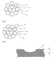
- FIG. 2 each illustrate a cross-sectional view of a preferable example of a steel cord according to the present invention.
- the steel cord illustrated in (a) of Fig. 2 is formed by disposing a sheath 22, formed by twisting nine sheath filaments 12 together, around a core 21 formed by twisting three core filaments 11 together.
- the steel cord illustrated in (b) of Fig. 2 has the same structure as that of the steel cord illustrated in (a) of Fig. 2 , except for the use of eight sheath filaments 12.
- the steel cord according to a preferred embodiment of the present invention includes no wrap filament 13 which is looped around and constrains the sheath 22, as in a cord having the conventional structure shown in Fig. 3 .
- Wear can be suppressed by excluding a wrap filament from the steel cord to keep the cord strength high and, in turn, to keep the cord fracture life long, thereby further improving the durability of the carcass ply.
- steel cords satisfying the above-described condition according to the present invention for all plies need to be used to obtain an expected effect.
- the belt layers 6 is formed by covering with rubber a plurality of steel cords arranged in parallel at an angle of, for example, 15 to 55° with respect to the tire circumferential direction, and at least two belt layers are generally arranged alternately with at least one layer between them, although four belt layers are used in the example illustrated in Fig. 1 .
- a tread pattern is formed on the surface of the tread portion 3 as appropriate and an inner liner (not illustrated) is formed in the innermost layer.
- an inert gas such as nitrogen or air that is general or has undergone a change in oxygen partial pressure can be employed as a gas used to fill the tire.
- the present invention is useful especially in applying it to a heavy-duty pneumatic tire used for heavy-duty vehicles such as trucks and buses.
- the number of hits in the carcass ply means hereinafter the number of hits under the bead core.
- a heavy-duty tire having a size of 11R22.5 was fabricated by applying steel cords to one carcass ply in accordance with conditions shown in the following table.
- Four belt layers (material: steel cords) were arranged at angles of +50°, +20°, -20°, and -20° with respect to the tire circumferential direction in turn from inside in the tire radial direction.
- the total weights of steel cords contained per unit area in carcass plies used in respective Examples and Comparative Examples were evaluated and represented by index numbers assuming that the total weight of steel cords according to Example 1-1 is 100. The smaller the numerical value, the lighter the weight and the better the result.
- the total tensile fracture strengths of steel cords used in respective Examples and Comparative Examples were evaluated and represented by index numbers assuming that the total tensile fracture strength of steel cords according to Example 1-1 is 100. The larger the numerical value, the higher the tensile fracture strength and the better the result.
- the durability of the bead portions was evaluated for tires to be tested according to respective Examples and Comparative Examples. More specifically, hydraulic pressure was applied into a tire assembled with a rim until the tire breaks, and it was checked whether filament breakage had occurred in the carcass cords near the bead cores after failure. The result was represented by ⁇ for no wire breakage and ⁇ for wire or cord breakage.
- Example Example 1-1 Example 1-2
- Example 1-3 Example 1-4
- Example 1-5 Example 1-6 Filament Tensile Strength T (MPa) 3050 3500 3900
- 3050 3500 3900 Cord Structure 3+9 ⁇ 0.13 3+9 ⁇ 0.13 3+9 ⁇ 0.13 3+9 ⁇ 0.15 3+9 ⁇ 0.15 3+9 ⁇ 0.15
- Cord Diameter d (mm) 0.54 0.54 0.54 0.62 0.62 0.62
- Number of Hits E (Hits/25mm) 36.8 32.1 28.8 27.4 24.1 21.5 a 1 T-b 1 0.693 0.858 1.004 0.693 0.858 1.004 a 2 T+b 2 0.536 0.500 0.468 0.536 0.500 0.468
- Total Cord Weight (Index Number) 100 87 79 100 88 78
- a truck radial tire having a size of 11R22.5 14PR was fabricated by applying steel cords to the carcass ply in accordance with conditions shown in the following table. Only one carcass ply was used. Four belt layers were arranged at angles of +50°, +20°, -20°, and -20° with respect to the tire circumferential direction in turn from inside in the tire radial direction. The carcass strength was represented by index numbers assuming that the carcass strength of a tire according to Comparative Example 2-1 is 100.
- the amount of steel cords contained in the carcass ply per unit area was evaluated for tires in respective Examples, Comparative Examples, and Reference Examples and represented by index numbers assuming that the amount of steel cords according to Comparative Example 2-1 is 100. The smaller the numerical value, the lighter the weight and the better the result.
- a 100,000-km drum running test was conducted at a speed of 60 km/h, an internal pressure of 8 kgf/cm 2 , and a load of JIS 100% for tires in respective Examples, Comparative Examples, and Reference Examples, and 10 carcass cords were extracted from each tire after running.
- the fracture strength was measured for these 10 carcass cords using an Instron tensile tester, the average of measured fracture strengths was divided by the average of fracture strengths similarly obtained for 10 cords extracted from identical portions in new tires in respective Examples and Comparative Examples, and the quotient was defined in terms of percentage as a cord strength holding rate (%). The closer to 100 the numerical value, the higher the holding rate and the better the result.
- a 100,000-km drum running test was conducted at a speed of 60 km/h, an internal pressure of 8 kgf/cm 2 , and a load of JIS 100% for tires in respective Examples, Comparative Examples, and Reference Examples, and one carcass cord was extracted from the carcass of each tire after running.
- the maximum value d ( ⁇ m) of the depth of wear of the sheath filaments 12 of the carcass cord due to contact between the bead cores and the steel cords in folding portions of the bead cores was measured (see Fig. 4 ). The smaller the numerical value, the smaller the amount of wear and the better the result.
- a drum running test for running over 20,000 km or until failure occurs was conducted at a speed of 60 km/h, an internal pressure of 1 kgf/cm 2 , and a load of JIS 40% for tires in respective Examples, Comparative Examples, and Reference Examples, and 10 carcass cords were extracted from the carcass of each tire after running.
- the number of broken filaments among these 10 carcass cords was counted and divided by the total number of filaments corresponding to the 10 cords, and the quotient was defined in terms of percentage as a filament breakage rate (%). The smaller the numerical value, the smaller the amount of filament breakage and the better the result.
- a side-cut test in which the sidewall portion collides against a squared timber modeled on a curbstone from the shoulder portion of the tire was conducted at a speed of 60 km/h, an internal pressure of 8 kgf/cm 2 , and a load of JIS 100% for tires in respective Examples, Comparative Examples, and Reference Examples, and 10 carcass cords were extracted from the carcass of each tire after running.
- the number of broken filaments among these 10 carcass cords was counted and divided by the total number of filaments corresponding to the 10 cords, and the quotient was defined in terms of percentage as a filament breakage rate (%). The smaller the numerical value, the smaller the amount of filament breakage and the better the result.
- Breakage properties in the manufacturing process were evaluated for steel filaments used in respective Examples, Comparative Examples, and Reference Examples. The result was represented by ⁇ for a level at which continuous production is possible with no breakage, ⁇ for a level at which continuous production is possible, and ⁇ for a level at which continuous production is impossible due to much breakage.
Landscapes
- Engineering & Computer Science (AREA)
- Mechanical Engineering (AREA)
- Tires In General (AREA)
- Ropes Or Cables (AREA)
Abstract
Description
- The present invention relates to a pneumatic tire (to be also simply referred to as a "tire" hereinafter) and, more particularly, to a heavy-duty pneumatic tire used for heavy-duty vehicles such as trucks and buses, especially to a refinement to its carcass ply cords.
- In recent years, to reduce the environmental load, it has become an important issue to reduce the weight and the amount of material used, for a tire as well. To tackle this issue, when the amount of material used for a carcass ply serving as a framework member of a tire is assumed to be reduced, it is necessary to maintain a given tire strength in the carcass ply and, in turn, to increase the tensile strength of carcass ply cords, i.e., their tensile fracture strength per unit cross-sectional area.
- Conventionally, a so-called multilayer twisted steel cord formed by twisting steel filaments together in two or three layers is commonly employed for the carcass ply of a pneumatic tire used for heavy-duty vehicles such as trucks and buses.
- As a technique associated with a refinement to carcass ply cords used for a tire,
patent document 1, for example, discloses a steel cord for rubber product reinforcement including a core made of three steel filaments, a first sheath made of nine steel filaments printed with a wave pattern, and a second sheath made of 15 steel filaments printed with a wave pattern.Patent document 2 discloses a pneumatic tire with its carcass reinforced by steel cords having cores each including a plurality of steel filaments and sheaths, each of which is formed by twisting together a plurality of steel filaments having the same diameter as that of the core in the same direction and is disposed around the core, and not having wrap filaments which are looped around the sheaths and constrain the steel filaments of the sheaths. In the steel cord, three steel filaments having a predetermined diameter and tensile strength are used for the core, and eight such steel filaments for the sheath. -
- Patent Document 1: Japanese Unexamined Patent Application Publication No.
H7-292585 - Patent Document 2: Japanese Unexamined Patent Application Publication No.
H11-28906 - As described above, to reduce the amount of material used for the carcass ply, it is necessary to increase the tensile strength of the carcass ply cords per unit area. However, as the tensile strength increases, the cords become more vulnerable to shear deformation that occurs in response to input in a direction perpendicular to the longitudinal direction due to embrittlement of steel products. This lowers the cord tensile fracture strength in the contact portions between the bead cores and the carcass ply cords, resulting in a higher rate of tire failure due to cord breakage.
- To solve this problem, durability can be improved by interposing a member made of, for example, hard rubber or an organic fiber between the bead cores and the carcass ply. This, however, leads to a heavier weight. Therefore, an established technique has been demanded which achieves a lighter-weight tire by reducing the amount of material used for the carcass ply without degrading the durability of bead portions.
- It is an object of the present invention to solve the above-mentioned problem and provide a pneumatic tire having its weight reduced without degrading the durability of bead portions.
- To achieve a lighter-weight tire without lowering the strength of the carcass ply in the conventional multilayer twisted steel cord, the use of high-tensile filaments is effective to reduce the amount of steel used. However, because especially filaments having a wire diameter as small as 0.20 mm or less are prone to breakage in the manufacturing process, high-tensile cords are hard to use.
- In view of this, it is another object of the present invention to provide a pneumatic tire having both a sufficient carcass strength and a lighter weight while improving the durability of the carcass ply and suppressing breakage in the manufacturing process by refining a multilayer twisted steel cord structure used for the carcass ply.
- The inventor of the present invention conducted a close examination and concluded that the above-mentioned problems can be solved by defining the cord diameter of a steel cord used for the carcass ply, based on the relationship with the tensile strength of steel filaments (steel wires) used for the steel cord, and defining the tensile strength of the steel filaments and the number of hits per unit width of the steel cord within predetermined ranges. This inventor thus completed the present invention.
- More specifically, the present invention provides a pneumatic tire comprising, as a framework, at least one carcass ply comprising a steel cord covered with rubber, wherein letting d (mm) be the cord diameter of the steel cord and T (MPa) be the tensile strength of a steel filament forming the steel cord, the following relation is satisfied:

- In the present invention, the tensile strength T of the steel filament is preferably 3200 MPa (exclusive) to 3800 MPa (exclusive). Furthermore, in the present invention, the number of hits E of the steel cord is preferably 14 hits/25 mm (exclusive) to 30 hits/25 mm (exclusive).
- Moreover, in the present invention, it is also preferable that the steel cord comprises a two-layer twisted cord formed by twisting together steel filaments having a wire diameter of 0.15 to 0.20 mm and a tensile strength T of 3140 to 3630 MPa in one of a 3+8 structure and a 3+9 structure comprising a core and a sheath, and a wrap filament which is looped around the sheath and constrains the sheath should be excluded from the steel cord.
- According to the present invention, the aforementioned configuration achieves a pneumatic tire having its weight reduced without degrading the durability of bead portions.
- Further, according to the present invention, the aforementioned configuration achieves a pneumatic tire having both a sufficient carcass strength and a lighter weight while improving the durability of the carcass ply and suppressing breakage in the manufacturing process.
-
-
Fig. 1 is a widthwise one-sided cross-sectional view illustrating an example of a pneumatic tire according to the present invention. - (a) and (b) of
Fig. 2 each illustrate a cross-sectional view of a preferable example of a steel cord according to the present invention. -
Fig. 3 is a cross-sectional view showing a steel cord in the conventional example. -
Fig. 4 is a view for explaining a method for measuring the depth of wear of a steel cord according to Examples. - Embodiments of the present invention will be described in detail below with reference to the drawings.
-
Fig 1 is a widthwise one-sided cross-sectional view illustrating an example of a pneumatic tire according to the present invention. The tire according to the present invention includes a pair of left andright bead portions 1,sidewall portions 2 extending outwards in the tire radial direction from thebead portions 1, and atread portion 3 connecting the twosidewall portions 2 together, as illustrated inFig. 1 . The tire according to the present invention further has, as a framework, acarcass 5 extending in a toroidal shape across a pair ofbead cores 4 embedded in the pair ofbead portions 1, respectively, and includes at least two (in the example illustrated inFig. 1 , four)belt layers 6 outside the crown portion of thecarcass 5 in the tire radial direction. - In the present invention, it is important that the
carcass 5 should be made of at least one carcass ply having steel cords covered with rubber and the steel cords forming the carcass ply should satisfy the following predetermined condition. - Letting d (mm) be the cord diameter of a steel cord used for the above-mentioned carcass ply and T (MPa (N/mm2)) be the tensile strength of a steel filament forming the steel cord, the tire according to the present invention needs to satisfy a relation:

- Conventionally, steel cords having a cord diameter larger than the range specified by the above-mentioned tensile strength T have been used. In this case, however, since input in a direction perpendicular to the longitudinal direction of the cords from the bead cores is large, an attempt to achieve a lighter weight by increasing the tensile strength degrades the durability of the bead portions, and a heavier weight is required to satisfy the durability of the bead portions. Therefore, a sufficient durability in bead portions and a lighter weight cannot be achieved simultaneously. On the other hand, steel cords having a cord diameter smaller than the above-mentioned range are too thin to ensure a sufficient cord tensile fracture strength, thus making it impossible to ensure a strength required by the tire.
- Furthermore, in the present invention, the tensile strength T of the above-mentioned steel filaments needs to be 3000 MPa (exclusive) to 4000 MPa (exclusive) and more preferably 3200 MPa (exclusive) to 3800 MPa (exclusive). When the tensile strength T of the steel filaments is 3000 MPa or less, a relatively large amount of steel is required to be used to ensure a given strength, thus making it difficult to achieve a lighter-weight tire. On the other hand, cords including steel filaments having a tensile strength T of 4000 MPa or more are hard to manufacture and are therefore impractical.
- Moreover, in the present invention, the number of hits E under the
bead core 4 of the steel cord in the carcass ply needs to be 12 hits/25 mm (exclusive) to 38 hits/25 mm (exclusive) and more preferably 14 hits/25 mm (exclusive) to 30 hits/25 mm (exclusive). The number of hits under thebead core 4 of the steel cord in the carcass ply means herein the number of hits in afolding region 5a of the carcass ply illustrated inFig. 1 . When the number of hits E is 12 hits/25 mm or less, a required tire strength cannot be ensured. On the other hand, when the number of hits E is 38 hits/25 mm or more, the carcass ply cords come into contact with each other in the contact portions between the carcass ply and the bead cores, thus lowering the durability of the bead portions. - In the present invention, since it is important only that steel cords satisfying the above-described predetermined condition should be applied to the carcass ply, specific configurations of the steel cords other than this point of importance, details of the tire construction, the material of each member, and the like are not particularly limited and may be selectively specified from the conventionally known ones as appropriate.
- The cord diameter d of the above-mentioned steel cords used in the present invention is preferably, for example, 0.50 to 0.80 mm. Further, examples of the specific structure of the above-mentioned steel cords used in the present invention may include the 3+9 and 3+8 structures.
- In particular, in the present invention, a two-layer twisted cord formed by twisting together steel filaments having a wire diameter of 0.15 to 0.20 mm and a tensile strength T of 3140 to 3630 MPa (320 to 370 kgf/mm2) in the 3+8 or 3+9 structure including a core and a sheath is preferably employed.
- In this case, reducing the diameter of the steel filaments results in less flexural strain to improve the durability of the carcass ply, and the use of steel filaments having a high tensile strength within an appropriate range makes it possible to ensure a given carcass strength and achieve a lighter weight, with less concerns for breakage in the manufacturing process. Further, the use of steel cords having a two-layer twisted structure: the 3+8 or 3+9 structure also allows a small cord diameter and a reduction in amount of rubber used for the carcass ply, and this is preferable in terms of achieving a lighter-weight tire.
- When the steel filaments have a wire diameter larger than 0.20 mm, the filaments are more prone to breakage and the durability of the carcass ply is relatively low, because the flexural strain is relatively high. On the other hand, when the steel filaments have a wire diameter smaller than 0.15 mm, breakage is more likely to occur in the manufacturing process. Note herein that it is crucial to use steel filaments having a small wire diameter of 0.15 to 0.20 mm. Especially when the present invention is applied to a low-profile tire having a tire profile of about 70% at which a high strain occurs in the sidewall portions, filaments having a smaller wire diameter of 0.15 to 0.175 mm are preferably used to suppress filament breakage.
- In a cord having the 3+8 or 3+9 structure and formed by using steel filaments having a small wire diameter of 0.15 to 0.20 mm, the ensuring of a given carcass strength and the fabrication of a lighter-weight tire cannot be achieved simultaneously when the tensile strength of the steel filaments is lower than 3140 MPa, while breakage is more likely to occur in the manufacturing process when this tensile strength is higher than 3630 MPa.
- (a) and (b) of
Fig. 2 each illustrate a cross-sectional view of a preferable example of a steel cord according to the present invention. The steel cord illustrated in (a) ofFig. 2 is formed by disposing asheath 22, formed by twisting ninesheath filaments 12 together, around acore 21 formed by twisting threecore filaments 11 together. The steel cord illustrated in (b) ofFig. 2 has the same structure as that of the steel cord illustrated in (a) ofFig. 2 , except for the use of eightsheath filaments 12. - As illustrated in
Fig. 2 , the steel cord according to a preferred embodiment of the present invention includes nowrap filament 13 which is looped around and constrains thesheath 22, as in a cord having the conventional structure shown inFig. 3 . Wear can be suppressed by excluding a wrap filament from the steel cord to keep the cord strength high and, in turn, to keep the cord fracture life long, thereby further improving the durability of the carcass ply. - In the preferred embodiment of the present invention, when at least two carcass plies are used, steel cords satisfying the above-described condition according to the present invention for all plies need to be used to obtain an expected effect.
- In the present invention, at least one carcass ply needs to be disposed but two or more carcass plies may be arranged, and the carcass plies are typically folded and locked from the tire inside to outside around the
bead cores 4, as illustrated inFig. 1 . Further, the belt layers 6 is formed by covering with rubber a plurality of steel cords arranged in parallel at an angle of, for example, 15 to 55° with respect to the tire circumferential direction, and at least two belt layers are generally arranged alternately with at least one layer between them, although four belt layers are used in the example illustrated inFig. 1 . - Additionally, in the tire illustrated in
Fig. 1 , a tread pattern is formed on the surface of thetread portion 3 as appropriate and an inner liner (not illustrated) is formed in the innermost layer. Further, an inert gas such as nitrogen or air that is general or has undergone a change in oxygen partial pressure can be employed as a gas used to fill the tire. The present invention is useful especially in applying it to a heavy-duty pneumatic tire used for heavy-duty vehicles such as trucks and buses. - The present invention will be described in more detail below with reference to Examples.
- The number of hits in the carcass ply means hereinafter the number of hits under the bead core.
- A heavy-duty tire having a size of 11R22.5 was fabricated by applying steel cords to one carcass ply in accordance with conditions shown in the following table. Four belt layers (material: steel cords) were arranged at angles of +50°, +20°, -20°, and -20° with respect to the tire circumferential direction in turn from inside in the tire radial direction.
- The total weights of steel cords contained per unit area in carcass plies used in respective Examples and Comparative Examples were evaluated and represented by index numbers assuming that the total weight of steel cords according to Example 1-1 is 100. The smaller the numerical value, the lighter the weight and the better the result.
- The total tensile fracture strengths of steel cords used in respective Examples and Comparative Examples were evaluated and represented by index numbers assuming that the total tensile fracture strength of steel cords according to Example 1-1 is 100. The larger the numerical value, the higher the tensile fracture strength and the better the result.
- The durability of the bead portions was evaluated for tires to be tested according to respective Examples and Comparative Examples. More specifically, hydraulic pressure was applied into a tire assembled with a rim until the tire breaks, and it was checked whether filament breakage had occurred in the carcass cords near the bead cores after failure. The result was represented by ○ for no wire breakage and × for wire or cord breakage.
- The productivities of steel cords used in respective Examples and Comparative Examples were evaluated based on the number of breakages that have occurred in manufacturing 100,000-m wires in the final wire drawing process of the wire manufacture. The result was represented by ○ for less than one breakages/100,000 m and × for one or more breakages/100,000 m.
- These results are shown together in the following table.
[Table 1] Example Example 1-1 Example 1-2 Example 1-3 Example 1-4 Example 1-5 Example 1-6 Filament Tensile Strength T (MPa) 3050 3500 3900 3050 3500 3900 Cord Structure 3+9×0.13 3+9×0.13 3+9×0.13 3+9×0.15 3+9×0.15 3+9×0.15 Cord Diameter d (mm) 0.54 0.54 0.54 0.62 0.62 0.62 Number of Hits E (Hits/25mm) 36.8 32.1 28.8 27.4 24.1 21.5 a1T-b1 0.693 0.858 1.004 0.693 0.858 1.004 a2T+b2 0.536 0.500 0.468 0.536 0.500 0.468 Total Cord Weight (Index Number) 100 87 79 100 88 78 Total Cord Strength (Index Number) 100 100 100 100 101 100 Durability of Bead Portions ○ ○ ○ ○ ○ ○ Cord Productivity ○ ○ ○ ○ ○ ○ [Table 2] Example 1-7 Example 1-8 Example 1-9 Example 1-10 Example 1-11 Comparative Example 1-1 Filament Tensile Strength T (MPa) 3050 3500 3900 3900 3900 2800 Cord Structure 3+8×0.16 3+8×0.20 3+8×0.23 3+8×0.20 3+9×0.115 3+8x0.16 Cord Diameter d (mm) 0.66 0.83 0.95 0.83 0.48 0.66 Number of Hits E (Hits/25mm) 26.4 14.7 12.1 13.2 36.8 28.8 a1T-b1 0.693 0.858 1.004 1.004 1.004 0.602 a2T+b2 0.536 0.500 0.468 0.468 0.468 0.556 Total Cord Weight (Index Number) 100 88 96 78 78 109 Total Cord Strength (Index Number) 100 100 122 100 100 100 Durability of Bead Portions ○ ○ ○ ○ ○ ○ Cord Productivity ○ ○ ○ ○ ○ ○ [Table 3] Comparative Example 1-2 Comparative Example 1-3 Comparative Example 1-4 Comparative Example 1-5 Comparative Example 1-6 Comparative Example 1-7 Filament Tensile Strength T (MPa) 2800 2800 3050 3500 3900 4050 Cord Structure 3+9×0.13 3+9×0.115 3+9×0.115 3+9×0.115 2+8×0.115 3+9×0.115 Cord Diameter d (mm) 0.54 0.48 0.48 0.48 0.46 0.48 Number of Hits E (Hits/25mm) 36.6 40.3 40.1 40.3 41.6 35.4 a1T-b1 0.602 0.602 0.693 0.858 1.004 1.058 a2T+b2 0.556 0.556 0.536 0.500 0.468 0.456 Total Cord Weight (Index Number) 100 86 85 86 74 75 Total Cord Strength (Index Number) 92 79 85 98 94 100 Durability of Bead Portions ○ ○ ○ ○ ○ ○ Cord Productivity ○ ○ ○ ○ ○ × [Table 4] Comparative Example 1-8 Comparative Example 1-9 Comparative Example 1-10 Comparative Example 1-11 Comparative Example 1-12 Comparative Example 1-13 Filament Tensile Strength T (MPa) 4050 4050 4050 3050 3500 3900 Cord Structure 3+9×0.13 1×5×0.25 2+8×0.25 3+9×0.18 3+8×0.22 3+9×0.25 Cord Diameter d (mm) 0.54 0.675 1.00 0.75 0.91 1.03 Number of Hits E (Hits/25mm) 27.8 18.0 8.8 19.1 12.1 8.7 a1T-b1 1.058 1.058 1.058 0.693 0.858 1.004 a2T+b2 0.456 0.456 0.456 0.536 0.500 0.468 Total Cord Weight (Index Number) 76 76 76 100 87 81 Total Cord Strength (Index Number) 100 101 100 100 100 103 Durability of Bead Portions ○ ○ ○ × × × Cord Productivity × × × ○ O O - As shown in the above-described table, in each Example in which steel cords satisfying a predetermined condition according to the present invention were used for the carcass ply, it was confirmed that lightweight properties can be ensured by keeping the cord weight light without deteriorating the total tensile fracture strength of the cords or the durability of the bead portions. Further, the cords used in each Example were excellent in terms of productivity as well.
- A truck radial tire having a size of 11R22.5 14PR was fabricated by applying steel cords to the carcass ply in accordance with conditions shown in the following table. Only one carcass ply was used. Four belt layers were arranged at angles of +50°, +20°, -20°, and -20° with respect to the tire circumferential direction in turn from inside in the tire radial direction. The carcass strength was represented by index numbers assuming that the carcass strength of a tire according to Comparative Example 2-1 is 100.
- The amount of steel cords contained in the carcass ply per unit area was evaluated for tires in respective Examples, Comparative Examples, and Reference Examples and represented by index numbers assuming that the amount of steel cords according to Comparative Example 2-1 is 100. The smaller the numerical value, the lighter the weight and the better the result.
- A 100,000-km drum running test was conducted at a speed of 60 km/h, an internal pressure of 8 kgf/cm2, and a load of JIS 100% for tires in respective Examples, Comparative Examples, and Reference Examples, and 10 carcass cords were extracted from each tire after running. The fracture strength was measured for these 10 carcass cords using an Instron tensile tester, the average of measured fracture strengths was divided by the average of fracture strengths similarly obtained for 10 cords extracted from identical portions in new tires in respective Examples and Comparative Examples, and the quotient was defined in terms of percentage as a cord strength holding rate (%). The closer to 100 the numerical value, the higher the holding rate and the better the result.
- A 100,000-km drum running test was conducted at a speed of 60 km/h, an internal pressure of 8 kgf/cm2, and a load of JIS 100% for tires in respective Examples, Comparative Examples, and Reference Examples, and one carcass cord was extracted from the carcass of each tire after running. The maximum value d (µm) of the depth of wear of the
sheath filaments 12 of the carcass cord due to contact between the bead cores and the steel cords in folding portions of the bead cores was measured (seeFig. 4 ). The smaller the numerical value, the smaller the amount of wear and the better the result. - A drum running test for running over 20,000 km or until failure occurs was conducted at a speed of 60 km/h, an internal pressure of 1 kgf/cm2, and a load of JIS 40% for tires in respective Examples, Comparative Examples, and Reference Examples, and 10 carcass cords were extracted from the carcass of each tire after running. The number of broken filaments among these 10 carcass cords was counted and divided by the total number of filaments corresponding to the 10 cords, and the quotient was defined in terms of percentage as a filament breakage rate (%). The smaller the numerical value, the smaller the amount of filament breakage and the better the result.
- A side-cut test in which the sidewall portion collides against a squared timber modeled on a curbstone from the shoulder portion of the tire was conducted at a speed of 60 km/h, an internal pressure of 8 kgf/cm2, and a load of JIS 100% for tires in respective Examples, Comparative Examples, and Reference Examples, and 10 carcass cords were extracted from the carcass of each tire after running. The number of broken filaments among these 10 carcass cords was counted and divided by the total number of filaments corresponding to the 10 cords, and the quotient was defined in terms of percentage as a filament breakage rate (%). The smaller the numerical value, the smaller the amount of filament breakage and the better the result.
- Breakage properties in the manufacturing process were evaluated for steel filaments used in respective Examples, Comparative Examples, and Reference Examples. The result was represented by ⊚ for a level at which continuous production is possible with no breakage, ○ for a level at which continuous production is possible, and × for a level at which continuous production is impossible due to much breakage.
- These results are shown together in the following table.
[Table 5] Comparative Example 2-1 Comparative Example 2-2 Comparative Example 2-3 Comparative Example 2-4 Comparative Example 2-5 Steel Cord Specifications Corresponding View Fig. 3 (a) of Fig. 2 (a) of Fig. 2 (a) of Fig. 2 (a) of Fig. 2 Twisted Structure 3+9+1 3+9 3+9 3+9 3+9 Filament Diameter (mm) 0.225/0.15 0.225 0.225 0.21 0.21 Direction of Twist S/S/Z S/S S/S S/S S/S Twist Pitch (mm) 6.0/12.0/3.5 6.0/12.0 6.0/12.0 5.5/11.5 5.5/11.5 Filament Tensile Strength T (MPa) 2940 2940 3630 3630 2940 Cord Diameter d (mm) - 0.935 0.935 0.875 0.875 a1T-b1 - 0.653 0.905 0.905 0.653 a2T+b2 - 0.545 0.490 0.490 0.545 Number of Hits in Carcass (Hits/25 mm) 12.5 12.5 10.1 11.6 14.3 Carcass Strength (Index Number) 100 100 100 100 100 Amount of Steel Cords Used for Carcass Ply (Index Number) 100 96 78 78 96 Cord Strength Holding Rate After Drum Running Under Normal Conditions (%) 88 99 100 99 100 Depth of Wear in Bead Portions After Drum Running Under Normal Conditions (µm) 15 17 25 15 12 Filament Breakage Rate After Drum Running Under Large Bending Condition (%) 30 75 78 11 10 Filament Breakage Rate After Side-cut Test (%) 15 18 23 14 10 Breakage Properties in Manufacturing Process ⊚ ⊚ ⊚ ⊚ ⊚ [Table 6] Comparative Example 2-6 Comparative Example 2-7 Comparative Example 2-8 Example 2-1 Example 2-2 Steel Cord Specif icatio ns Corresponding View (a) of Fig. 2 (a) of Fig. 2 (a) of Fig. 2 (a) of Fig. 2 (a) of Fig. 2 Twisted Structure 3+9 3+9 3+9 3+9 3+9 Filament Diameter (mm) 0.21 0.21 0.20 0.20 0.175 Direction of Twist S/S S/S S/S S/S S/S Twist Pitch (mm) 5.0/10.0 5.5/11.5 5.4/10.7 5.4/10.7 4.8/9.4 Filament Tensile Strength T (MPa) 3920 3040 3040 3630 3630 Cord Diameter d (mm) 0.87 0.87 0.831 0.831 0.727 a1T-b1 1.011 0.690 0.690 0.905 0.905 a2T+b2 0.466 0.537 0.537 0.490 0.490 Number of Hits in Carcass (Hits/25 mm) 10.7 13.8 15.2 12.8 16.7 Carcass Strength (Index Number) 100 100 100 100 100 Amount of Steel Cords Used for Carcass Ply (Index Number) 72 93 93 78 78 Cord Strength Holding Rate After Drum Running Under Normal Conditions (%) 99 100 100 100 100 Depth of Wear in Bead Portions After Drum Running Under Normal Conditions (µm) 22 2 3 2 1 Filament Breakage Rate After Drum Running Under Large Bending Condition (%) 12 10 0 1 0 Filament Breakage Rate After Side-cut Test (%) 33 2 1 3 0 Breakage Properties in Manufacturing Process × ⊚ ⊚ ⊚ ○ [Table 7] Example 2-3 Reference Example 2-1 Reference Example 2-2 Example 2-4 Example 2-5 Corresponding View (a) of Fig. 2 (a) of Fig. 2 (a) of Fig. 2 (a) of Fig. 2 (a) of Fig. 2 Twisted Structure 3+9 3+9 3+9 3+9 3+9 Steel Cord Specif icatio ns Filament Diameter (mm) 0.15 0.20 0.175 0.15 0.20 Direction of Twist S/S S/S S/S S/S S/S Twist Pitch (mm) 4.2/8.0 5.4/10.7 4.8/9.4 4.2/8.0 5.4/10.7 Filament Tensile Strength T (MPa) 3630 3140 3140 3140 3430 Cord Diameter d (mm) 0.6231 0.831 0.727 0.623 0.831 a1T-b1 0.905 0.726 0.726 0.726 0.832 a2T+b2 0.4890 0.529 0.529 0.529 0.506 Number of Hits in Carcass (Hits/25 mm) 22.7 14.6 19 26 13.4 Carcass Strength (Index Number) 100 100 100 100 100 Amountof Steel Cords Used for CarcassPly (Index Number) 78 90 90 90 82 Cord Strength Holding Rate After Drum Running Under Normal Conditions (%) 100 100 100 100 100 Depth of Wear in Bead Portions After Drum Running Under Normal Conditions (µm) 0 1 0 0 0 Filament Breakage Rate After Drum Running Under Large Bending Condition (%) 0 0 0 0 0 Filament Breakage Rate After Side-cut Test (%) 0 0 0 0 2 Breakage Properties in Manufacturing Process ○ ⊚ ⊚ ⊚ ⊚ [Table 8] Example 2-6 Example 2-7 Corresponding View (a) of Fig. 2 (a) of Fig. 2 Twisted Structure 3+9 3+9 Steel Cord Specif icatio ns Filament Diameter (mm) 0.175 0.15 Direction of Twist S/S S/S Twist Pitch (mm) 4.8/9.4 4.2/8.0 Filament Tensile Strength T (MPa) 3430 3430 Cord Diameter d (mm) 0.728 0.623 a1T-b1 0.832 0.832 a2T+b2 0.506 0.506 Number of Hits in Carcass (Hits/25 mm) 17.5 23.8 Carcass Strength (Index Number) 100 100 Amount of Steel Cords Used for Carcass Ply (Index Number) 82 82 Cord Strength Holding Rate After Drum Running Under Normal Conditions (%) 100 100 Depth of Wear in Bead Portions After Drum Running Under Normal Conditions (µm) 0 0 Filament Breakage Rate After Drum Running Under Large Bending Condition (%) 0 0 Filament Breakage Rate After Side-cut Test (%) 0 0 Breakage Properties in Manufacturing Process ⊚ ○ - As shown in the above-described table, in a tire to be tested according to each Example which uses a steel cord formed by twisting steel filaments, having a wire diameter of 0.15 to 0.20 mm and a tensile strength of 3140 to 3630 MPa (N/mm2), with the carcass ply in the 3+9 structure, it was confirmed that good results were obtained for all evaluation items.
[Table 9] Comparative Example 2-9 Comparative Example 2-10 Comparative Example 2-11 Comparative Example 2-12 Comparative Example 2-13 Corresponding View (b) of Fig. 2 (b) of Fig. 2 (b) of Fig. 2 (b) of Fig. 2 (b) of Fig. 2 Twisted Structure 3+8 3+8 3+8 3+8 3+8 Steel Cord Specif icatio ns Filament Diameter (mm) 0.225 0.225 0.21 0.21 0.21 Direction of Twist S/S S/S S/S S/S S/S Twist Pitch (mm) 6.0/12.0 6.0/12.0 5.5/11.5 5.5/11.5 5.0/10.0 Filament Tensile Strength T (MPa) 2940 3630 3630 2940 3920 Cord Diameter d (mm) 0.935 0.935 0.872 0.872 0.872 a1T-b1 0.653 0.905 0.905 0.653 1.011 a2T+b2 0.545 0.490 0.90 0.545 0.466 Number of Hits in Carcass (Hits/25 mm) 13.6 11 12.6 15.6 11.7 Carcass Strength (Index Number) 100 100 100 100 100 Amount of Steel Cords Used for Carcass Ply (Index Number) 96 78 78 96 72 Cord Strength Holding Rate After Drum Running Under Normal Conditions (%) 99 100 99 100 99 Depth of Wear in Bead Portions After Drum Running Under Normal Conditions (µm) 13 16 13 12 17 Filament Breakage Rate After Drum Running Under Large Bending Condition (%) 81 80 15 12 10 Filament Breakage Rate After Side-cut Test (%) 22 16 11 10 22 Breakage Properties in Manufacturing Process ⊚ ⊚ ⊚ ⊚ × [Table 10] Comparative Example 2-14 Comparative Example 2-15 Example 2-8 Example 2-9 Example 2-10 Corresponding View (b) of Fig. 2 (b) of Fig. 2 (b) of Fig. 2 (b) of Fig. 2 (b) of Fig. 2 Twisted Structure 3+8 3+8 3+8 3+8 3+8 Steel Cord Specif icatio ns Filament Diameter (mm) 0.21 0.20 0.20 0.175 0.15 Direction of Twist S/S S/S S/S S/S S/S Twist Pitch (mm) 5.5/11.5 5.4/10.7 5.4/10.7 4.8/9.4 4.2/8.0 Filament Tensile Strength T (MPa) 3040 3040 3630 3630 3630 Cord Diameter d (mm) 0.8723 0.831 0.8318 0.727 0.623 a1T-b1 0.690 0.690 0.905 0.905 0.905 a2T+b2 0.537 0.537 0.490 0.490 0.490 Number of Hits in Carcass (Hits/25 mm) 15.1 16.6 14 18.2 24.7 Carcass Strength (Index Number) 100 100 100 100 100 Amount of Steel Cords Used for Carcass Ply (Index Number) 93 93 78 78 78 Cord Strength Holding Rate After Drum Running Under Normal Conditions (%) 100 100 100 100 100 Depth of Wear in Bead Portions After Drum Running Under Normal Conditions (µm) 3 0 1 0 0 Filament Breakage Rate After Drum Running Under Large Bending Condition (%) 11 0 0 0 0 Filament Breakage Rate After Side-cut Test (%) 3 0 2 0 0 Breakage Properties in Manufacturing Process ⊚ ⊚ ⊚ ○ ○ [Table 11] Reference Example 2-3 Reference Example 2-4 Example 2-11 Example 2-12 Example 2-13 Example 2-14 Steel Cord Specif icatio ns Corresponding View (b) of Fig. 2 (b) of Fig. 2 (b) of Fig. 2 (b) of Fig. 2 (b) of Fig. 2 (b) of Fig. 2 Twisted Structure 3+8 3+8 3+8 3+8 3+8 3+8 Filament Diameter (mm) 0.20 0.175 0.15 0.20 0.175 0.15 Direction of Twist S/S S/S S/S S/S S/S S/S Twist Pitch (mm) 5.4/10.7 4.8/9.4 4.2/8.0 5.4/10.7 4.8/9.4 4.2/8.0 Filament Tensile Strength T (MPa) 3140 3140 3140 3430 3430 3430 Cord Diameter d (mm) 0.831 0.727 0.623 0.831 0.727 0.623 a1T-b1 0.726 0.726 0.726 0.832 0.832 0.832 a2T+b2 0.529 0.529 0.529 0.506 0.506 0.506 Number of Hits in Carcass (Hits/25 mm) 16.1 21 28.7 14.7 19.2 26.1 Carcass Strength (Index Number) 100 100 100 100 100 100 Amount of Steel Cords Used for Carcass Ply (Index Number) 90 90 90 82 82 82 Cord Strength Holding Rate After Drum Running Under Normal Conditions (%) 100 100 100 100 100 100 Depth of Wear in Bead Portions After Drum Running Under Normal Conditions (µm) 1 0 0 0 0 0 Filament Breakage Rate After Drum Running Under Large Bending Condition (%) 0 0 0 0 0 0 Filament Breakage Rate After Side-cut Test (%) 0 0 0 2 0 0 Breakage Properties in Manufacturing Process ⊚ ⊚ ⊚ ⊚ ⊚ ○ - As shown in the above-described table, in a tire to be tested according to each Example which uses a steel cord formed by twisting steel filaments, having a wire diameter of 0.15 to 0.20 mm and a tensile strength of 3140 to 3630 MPa (N/mm2), with the carcass ply in the 3+8 structure, it was confirmed that good results were obtained for all evaluation items.
- 1, bead portion; 2, sidewall portion; 3, tread portion; 4, bead core; 5, carcass; 6, belt layer; 11, core filament; 12, sheath filament; 13, wrap filament; 21, core; 22, sheath.
Claims (5)
- A pneumatic tire comprising, as a framework, at least one carcass ply comprising a steel cord covered with rubber, wherein
letting d (mm) be a cord diameter of the steel cord and T (MPa) be a tensile strength of a steel filament forming the steel cord, the following relation is satisfied: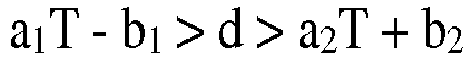
- The pneumatic tire according to claim 1, wherein the tensile strength T of the steel filament is 3200 MPa (exclusive) to 3800 MPa (exclusive).
- The pneumatic tire according to claim 1, wherein the number of hits E of the steel cord is 14 hits/25 mm (exclusive) to 30 hits/25 mm (exclusive).
- The pneumatic tire according to claim 2, wherein the number of hits E of the steel cord is 14 hits/25 mm (exclusive) to 30 hits/25 mm (exclusive).
- The pneumatic tire according to claim 1, wherein the steel cord comprises a two-layer twisted cord formed by twisting together steel filaments having a wire diameter of 0.15 to 0.20 mm and a tensile strength T of 3140 to 3630 MPa in one of a 3+8 structure and a 3+9 structure comprising a core and a sheath, and a wrap filament which is looped around the sheath and constrains the sheath is excluded from the steel cord.
Applications Claiming Priority (3)
| Application Number | Priority Date | Filing Date | Title |
|---|---|---|---|
| JP2013152009 | 2013-07-22 | ||
| JP2013152010 | 2013-07-22 | ||
| PCT/JP2014/069295 WO2015012255A1 (en) | 2013-07-22 | 2014-07-22 | Pneumatic tyre |
Publications (3)
| Publication Number | Publication Date |
|---|---|
| EP3025873A1 true EP3025873A1 (en) | 2016-06-01 |
| EP3025873A4 EP3025873A4 (en) | 2016-08-10 |
| EP3025873B1 EP3025873B1 (en) | 2019-09-04 |
Family
ID=52393290
Family Applications (1)
| Application Number | Title | Priority Date | Filing Date |
|---|---|---|---|
| EP14829520.7A Active EP3025873B1 (en) | 2013-07-22 | 2014-07-22 | Pneumatic tyre |
Country Status (5)
| Country | Link |
|---|---|
| US (1) | US20160167435A1 (en) |
| EP (1) | EP3025873B1 (en) |
| JP (1) | JP6440206B2 (en) |
| CN (1) | CN105492222A (en) |
| WO (1) | WO2015012255A1 (en) |
Cited By (1)
| Publication number | Priority date | Publication date | Assignee | Title |
|---|---|---|---|---|
| EP4116111A1 (en) * | 2021-07-09 | 2023-01-11 | Kumho Tire Co., Inc. | The pneumatic tire |
Families Citing this family (5)
| Publication number | Priority date | Publication date | Assignee | Title |
|---|---|---|---|---|
| CN111247292B (en) * | 2017-10-27 | 2023-08-04 | 贝卡尔特先进帘线阿尔特公司 | Steel cord for reinforcing elastomer |
| JP7309754B2 (en) * | 2018-12-13 | 2023-07-18 | 株式会社ブリヂストン | pneumatic tire |
| JP7251326B2 (en) * | 2019-06-03 | 2023-04-04 | 横浜ゴム株式会社 | pneumatic tire |
| JP7463712B2 (en) * | 2019-12-18 | 2024-04-09 | 住友ゴム工業株式会社 | Heavy-duty tubeless tire and manufacturing method |
| US11781945B2 (en) * | 2021-08-25 | 2023-10-10 | The Goodyear Tire & Rubber Company | Tire sidewall toughness index method |
Family Cites Families (12)
| Publication number | Priority date | Publication date | Assignee | Title |
|---|---|---|---|---|
| JPS59124404A (en) * | 1982-12-29 | 1984-07-18 | Bridgestone Corp | Pneumatic radial tire |
| JP3204579B2 (en) * | 1993-10-14 | 2001-09-04 | 株式会社ブリヂストン | Steel cord and pneumatic radial tire |
| JP2733438B2 (en) * | 1993-12-27 | 1998-03-30 | 住友ゴム工業株式会社 | Radial tires for trucks and buses |
| JP3529875B2 (en) | 1994-02-24 | 2004-05-24 | 株式会社ブリヂストン | Steel cord for reinforcing rubber articles and pneumatic radial tire |
| US6247514B1 (en) * | 1994-12-20 | 2001-06-19 | The Goodyear Tire & Rubber Company | Tires with high strength reinforcement |
| JP3708678B2 (en) * | 1997-05-15 | 2005-10-19 | 株式会社ブリヂストン | Pneumatic radial tire |
| JP2000071713A (en) * | 1998-09-02 | 2000-03-07 | Bridgestone Corp | Pneumatic radial tire |
| JP2000177312A (en) * | 1998-12-14 | 2000-06-27 | Bridgestone Corp | Pneumatic radial tire |
| JP2005219596A (en) * | 2004-02-05 | 2005-08-18 | Bridgestone Corp | Heavy duty pneumatic radial tire |
| FR2934614B1 (en) * | 2008-08-01 | 2010-09-10 | Michelin Soc Tech | IN SITU GAS BED CABLE FOR PNEUMATIC CARCASE REINFORCEMENT. |
| WO2010126084A1 (en) * | 2009-04-28 | 2010-11-04 | 株式会社ブリヂストン | Rubber article-reinforcing steel cord and pneumatic tire |
| DE102010000050A1 (en) * | 2010-01-12 | 2011-07-14 | Continental Reifen Deutschland GmbH, 30165 | Steel cord for use as strength carrier in e.g. belt ply of passenger car pneumatic tire, has core filament comprising tensile strength ranging between specific values, and coating filaments comprising strength larger than specific value |
-
2014
- 2014-07-22 CN CN201480041782.1A patent/CN105492222A/en active Pending
- 2014-07-22 WO PCT/JP2014/069295 patent/WO2015012255A1/en not_active Ceased
- 2014-07-22 JP JP2015528284A patent/JP6440206B2/en not_active Expired - Fee Related
- 2014-07-22 US US14/906,314 patent/US20160167435A1/en not_active Abandoned
- 2014-07-22 EP EP14829520.7A patent/EP3025873B1/en active Active
Cited By (1)
| Publication number | Priority date | Publication date | Assignee | Title |
|---|---|---|---|---|
| EP4116111A1 (en) * | 2021-07-09 | 2023-01-11 | Kumho Tire Co., Inc. | The pneumatic tire |
Also Published As
| Publication number | Publication date |
|---|---|
| JP6440206B2 (en) | 2018-12-19 |
| JPWO2015012255A1 (en) | 2017-03-02 |
| US20160167435A1 (en) | 2016-06-16 |
| EP3025873B1 (en) | 2019-09-04 |
| CN105492222A (en) | 2016-04-13 |
| EP3025873A4 (en) | 2016-08-10 |
| WO2015012255A1 (en) | 2015-01-29 |
Similar Documents
| Publication | Publication Date | Title |
|---|---|---|
| EP2423380B1 (en) | Steel cord for reinforcing rubber and pneumatic radial tire | |
| EP3025873B1 (en) | Pneumatic tyre | |
| EP2374928B1 (en) | Steel cord for reinforcement of rubber material and pneumatic tire | |
| RU2570190C2 (en) | Steel cord for reinforcing of rubber product and pneumatic tire cover with named cord | |
| EP2689939B1 (en) | Steel cord for rubber article reinforcement and pneumatic radial tire using same | |
| EP1902867B1 (en) | Pneumatic radial tire | |
| US9004128B2 (en) | Steel cord for reinforcing rubber article and pneumatic tire | |
| EP2298986A1 (en) | Steel cord for reinforcement of rubber product and pneumatic tire using same | |
| EP2641755B1 (en) | Pneumatic tire | |
| EP3132948B1 (en) | Tire | |
| JP5036294B2 (en) | Steel cords for reinforcing rubber articles and pneumatic tires | |
| JP4628239B2 (en) | Steel cords for reinforcing rubber articles and pneumatic radial tires | |
| EP1985748A1 (en) | Steel cord, rubber-steel cord composite and tire | |
| EP2657046B1 (en) | Pneumatic radial tire | |
| EP2808178B1 (en) | Tire reinforcing member and pneumatic tire using same | |
| JP5837399B2 (en) | Pneumatic radial tire for trucks and buses | |
| JP5602609B2 (en) | Steel cord for reinforcing rubber articles and pneumatic tire using the same | |
| JP5718085B2 (en) | Pneumatic tire | |
| JPH08170283A (en) | Steel cord for reinforcing rubber product and pneumatic tire | |
| JP6363321B2 (en) | Pneumatic tire | |
| JP5952715B2 (en) | Steel cord for reinforcing rubber articles and pneumatic radial tire using the same | |
| JP2007031890A (en) | Steel cord and pneumatic radial tire | |
| JPH09156315A (en) | Pneumatic radial tire | |
| JP5718087B2 (en) | Pneumatic tire | |
| JP2017082343A (en) | Steel cord for reinforcing rubber product, and pneumatic tire made therefrom |
Legal Events
| Date | Code | Title | Description |
|---|---|---|---|
| PUAI | Public reference made under article 153(3) epc to a published international application that has entered the european phase |
Free format text: ORIGINAL CODE: 0009012 |
|
| 17P | Request for examination filed |
Effective date: 20160212 |
|
| AK | Designated contracting states |
Kind code of ref document: A1 Designated state(s): AL AT BE BG CH CY CZ DE DK EE ES FI FR GB GR HR HU IE IS IT LI LT LU LV MC MK MT NL NO PL PT RO RS SE SI SK SM TR |
|
| AX | Request for extension of the european patent |
Extension state: BA ME |
|
| A4 | Supplementary search report drawn up and despatched |
Effective date: 20160708 |
|
| RIC1 | Information provided on ipc code assigned before grant |
Ipc: D07B 1/06 20060101ALI20160704BHEP Ipc: B60C 9/00 20060101AFI20160704BHEP |
|
| DAX | Request for extension of the european patent (deleted) | ||
| STAA | Information on the status of an ep patent application or granted ep patent |
Free format text: STATUS: EXAMINATION IS IN PROGRESS |
|
| 17Q | First examination report despatched |
Effective date: 20170630 |
|
| GRAP | Despatch of communication of intention to grant a patent |
Free format text: ORIGINAL CODE: EPIDOSNIGR1 |
|
| STAA | Information on the status of an ep patent application or granted ep patent |
Free format text: STATUS: GRANT OF PATENT IS INTENDED |
|
| INTG | Intention to grant announced |
Effective date: 20190225 |
|
| GRAS | Grant fee paid |
Free format text: ORIGINAL CODE: EPIDOSNIGR3 |
|
| GRAA | (expected) grant |
Free format text: ORIGINAL CODE: 0009210 |
|
| STAA | Information on the status of an ep patent application or granted ep patent |
Free format text: STATUS: THE PATENT HAS BEEN GRANTED |
|
| AK | Designated contracting states |
Kind code of ref document: B1 Designated state(s): AL AT BE BG CH CY CZ DE DK EE ES FI FR GB GR HR HU IE IS IT LI LT LU LV MC MK MT NL NO PL PT RO RS SE SI SK SM TR |
|
| REG | Reference to a national code |
Ref country code: GB Ref legal event code: FG4D |
|
| REG | Reference to a national code |
Ref country code: CH Ref legal event code: EP |
|
| REG | Reference to a national code |
Ref country code: AT Ref legal event code: REF Ref document number: 1174838 Country of ref document: AT Kind code of ref document: T Effective date: 20190915 |
|
| REG | Reference to a national code |
Ref country code: DE Ref legal event code: R096 Ref document number: 602014053136 Country of ref document: DE |
|
| REG | Reference to a national code |
Ref country code: IE Ref legal event code: FG4D |
|
| REG | Reference to a national code |
Ref country code: NL Ref legal event code: MP Effective date: 20190904 |
|
| REG | Reference to a national code |
Ref country code: LT Ref legal event code: MG4D |
|
| PG25 | Lapsed in a contracting state [announced via postgrant information from national office to epo] |
Ref country code: HR Free format text: LAPSE BECAUSE OF FAILURE TO SUBMIT A TRANSLATION OF THE DESCRIPTION OR TO PAY THE FEE WITHIN THE PRESCRIBED TIME-LIMIT Effective date: 20190904 Ref country code: LT Free format text: LAPSE BECAUSE OF FAILURE TO SUBMIT A TRANSLATION OF THE DESCRIPTION OR TO PAY THE FEE WITHIN THE PRESCRIBED TIME-LIMIT Effective date: 20190904 Ref country code: BG Free format text: LAPSE BECAUSE OF FAILURE TO SUBMIT A TRANSLATION OF THE DESCRIPTION OR TO PAY THE FEE WITHIN THE PRESCRIBED TIME-LIMIT Effective date: 20191204 Ref country code: SE Free format text: LAPSE BECAUSE OF FAILURE TO SUBMIT A TRANSLATION OF THE DESCRIPTION OR TO PAY THE FEE WITHIN THE PRESCRIBED TIME-LIMIT Effective date: 20190904 Ref country code: FI Free format text: LAPSE BECAUSE OF FAILURE TO SUBMIT A TRANSLATION OF THE DESCRIPTION OR TO PAY THE FEE WITHIN THE PRESCRIBED TIME-LIMIT Effective date: 20190904 Ref country code: NO Free format text: LAPSE BECAUSE OF FAILURE TO SUBMIT A TRANSLATION OF THE DESCRIPTION OR TO PAY THE FEE WITHIN THE PRESCRIBED TIME-LIMIT Effective date: 20191204 |
|
| PG25 | Lapsed in a contracting state [announced via postgrant information from national office to epo] |
Ref country code: RS Free format text: LAPSE BECAUSE OF FAILURE TO SUBMIT A TRANSLATION OF THE DESCRIPTION OR TO PAY THE FEE WITHIN THE PRESCRIBED TIME-LIMIT Effective date: 20190904 Ref country code: ES Free format text: LAPSE BECAUSE OF FAILURE TO SUBMIT A TRANSLATION OF THE DESCRIPTION OR TO PAY THE FEE WITHIN THE PRESCRIBED TIME-LIMIT Effective date: 20190904 Ref country code: GR Free format text: LAPSE BECAUSE OF FAILURE TO SUBMIT A TRANSLATION OF THE DESCRIPTION OR TO PAY THE FEE WITHIN THE PRESCRIBED TIME-LIMIT Effective date: 20191205 Ref country code: LV Free format text: LAPSE BECAUSE OF FAILURE TO SUBMIT A TRANSLATION OF THE DESCRIPTION OR TO PAY THE FEE WITHIN THE PRESCRIBED TIME-LIMIT Effective date: 20190904 Ref country code: AL Free format text: LAPSE BECAUSE OF FAILURE TO SUBMIT A TRANSLATION OF THE DESCRIPTION OR TO PAY THE FEE WITHIN THE PRESCRIBED TIME-LIMIT Effective date: 20190904 |
|
| REG | Reference to a national code |
Ref country code: AT Ref legal event code: MK05 Ref document number: 1174838 Country of ref document: AT Kind code of ref document: T Effective date: 20190904 |
|
| PG25 | Lapsed in a contracting state [announced via postgrant information from national office to epo] |
Ref country code: NL Free format text: LAPSE BECAUSE OF FAILURE TO SUBMIT A TRANSLATION OF THE DESCRIPTION OR TO PAY THE FEE WITHIN THE PRESCRIBED TIME-LIMIT Effective date: 20190904 Ref country code: AT Free format text: LAPSE BECAUSE OF FAILURE TO SUBMIT A TRANSLATION OF THE DESCRIPTION OR TO PAY THE FEE WITHIN THE PRESCRIBED TIME-LIMIT Effective date: 20190904 Ref country code: PL Free format text: LAPSE BECAUSE OF FAILURE TO SUBMIT A TRANSLATION OF THE DESCRIPTION OR TO PAY THE FEE WITHIN THE PRESCRIBED TIME-LIMIT Effective date: 20190904 Ref country code: EE Free format text: LAPSE BECAUSE OF FAILURE TO SUBMIT A TRANSLATION OF THE DESCRIPTION OR TO PAY THE FEE WITHIN THE PRESCRIBED TIME-LIMIT Effective date: 20190904 Ref country code: RO Free format text: LAPSE BECAUSE OF FAILURE TO SUBMIT A TRANSLATION OF THE DESCRIPTION OR TO PAY THE FEE WITHIN THE PRESCRIBED TIME-LIMIT Effective date: 20190904 Ref country code: PT Free format text: LAPSE BECAUSE OF FAILURE TO SUBMIT A TRANSLATION OF THE DESCRIPTION OR TO PAY THE FEE WITHIN THE PRESCRIBED TIME-LIMIT Effective date: 20200106 |
|
| PG25 | Lapsed in a contracting state [announced via postgrant information from national office to epo] |
Ref country code: SM Free format text: LAPSE BECAUSE OF FAILURE TO SUBMIT A TRANSLATION OF THE DESCRIPTION OR TO PAY THE FEE WITHIN THE PRESCRIBED TIME-LIMIT Effective date: 20190904 Ref country code: SK Free format text: LAPSE BECAUSE OF FAILURE TO SUBMIT A TRANSLATION OF THE DESCRIPTION OR TO PAY THE FEE WITHIN THE PRESCRIBED TIME-LIMIT Effective date: 20190904 Ref country code: IS Free format text: LAPSE BECAUSE OF FAILURE TO SUBMIT A TRANSLATION OF THE DESCRIPTION OR TO PAY THE FEE WITHIN THE PRESCRIBED TIME-LIMIT Effective date: 20200224 Ref country code: CZ Free format text: LAPSE BECAUSE OF FAILURE TO SUBMIT A TRANSLATION OF THE DESCRIPTION OR TO PAY THE FEE WITHIN THE PRESCRIBED TIME-LIMIT Effective date: 20190904 |
|
| REG | Reference to a national code |
Ref country code: DE Ref legal event code: R097 Ref document number: 602014053136 Country of ref document: DE |
|
| PLBE | No opposition filed within time limit |
Free format text: ORIGINAL CODE: 0009261 |
|
| STAA | Information on the status of an ep patent application or granted ep patent |
Free format text: STATUS: NO OPPOSITION FILED WITHIN TIME LIMIT |
|
| PG2D | Information on lapse in contracting state deleted |
Ref country code: IS |
|
| PG25 | Lapsed in a contracting state [announced via postgrant information from national office to epo] |
Ref country code: DK Free format text: LAPSE BECAUSE OF FAILURE TO SUBMIT A TRANSLATION OF THE DESCRIPTION OR TO PAY THE FEE WITHIN THE PRESCRIBED TIME-LIMIT Effective date: 20190904 Ref country code: IS Free format text: LAPSE BECAUSE OF FAILURE TO SUBMIT A TRANSLATION OF THE DESCRIPTION OR TO PAY THE FEE WITHIN THE PRESCRIBED TIME-LIMIT Effective date: 20200105 |
|
| 26N | No opposition filed |
Effective date: 20200605 |
|
| PG25 | Lapsed in a contracting state [announced via postgrant information from national office to epo] |
Ref country code: SI Free format text: LAPSE BECAUSE OF FAILURE TO SUBMIT A TRANSLATION OF THE DESCRIPTION OR TO PAY THE FEE WITHIN THE PRESCRIBED TIME-LIMIT Effective date: 20190904 |
|
| PG25 | Lapsed in a contracting state [announced via postgrant information from national office to epo] |
Ref country code: MC Free format text: LAPSE BECAUSE OF FAILURE TO SUBMIT A TRANSLATION OF THE DESCRIPTION OR TO PAY THE FEE WITHIN THE PRESCRIBED TIME-LIMIT Effective date: 20190904 |
|
| REG | Reference to a national code |
Ref country code: CH Ref legal event code: PL |
|
| GBPC | Gb: european patent ceased through non-payment of renewal fee |
Effective date: 20200722 |
|
| REG | Reference to a national code |
Ref country code: BE Ref legal event code: MM Effective date: 20200731 |
|
| PG25 | Lapsed in a contracting state [announced via postgrant information from national office to epo] |
Ref country code: LU Free format text: LAPSE BECAUSE OF NON-PAYMENT OF DUE FEES Effective date: 20200722 Ref country code: LI Free format text: LAPSE BECAUSE OF NON-PAYMENT OF DUE FEES Effective date: 20200731 Ref country code: CH Free format text: LAPSE BECAUSE OF NON-PAYMENT OF DUE FEES Effective date: 20200731 Ref country code: GB Free format text: LAPSE BECAUSE OF NON-PAYMENT OF DUE FEES Effective date: 20200722 |
|
| PG25 | Lapsed in a contracting state [announced via postgrant information from national office to epo] |
Ref country code: BE Free format text: LAPSE BECAUSE OF NON-PAYMENT OF DUE FEES Effective date: 20200731 |
|
| PG25 | Lapsed in a contracting state [announced via postgrant information from national office to epo] |
Ref country code: IE Free format text: LAPSE BECAUSE OF NON-PAYMENT OF DUE FEES Effective date: 20200722 |
|
| PG25 | Lapsed in a contracting state [announced via postgrant information from national office to epo] |
Ref country code: IT Free format text: LAPSE BECAUSE OF NON-PAYMENT OF DUE FEES Effective date: 20200722 |
|
| PG25 | Lapsed in a contracting state [announced via postgrant information from national office to epo] |
Ref country code: TR Free format text: LAPSE BECAUSE OF FAILURE TO SUBMIT A TRANSLATION OF THE DESCRIPTION OR TO PAY THE FEE WITHIN THE PRESCRIBED TIME-LIMIT Effective date: 20190904 Ref country code: MT Free format text: LAPSE BECAUSE OF FAILURE TO SUBMIT A TRANSLATION OF THE DESCRIPTION OR TO PAY THE FEE WITHIN THE PRESCRIBED TIME-LIMIT Effective date: 20190904 Ref country code: CY Free format text: LAPSE BECAUSE OF FAILURE TO SUBMIT A TRANSLATION OF THE DESCRIPTION OR TO PAY THE FEE WITHIN THE PRESCRIBED TIME-LIMIT Effective date: 20190904 |
|
| PG25 | Lapsed in a contracting state [announced via postgrant information from national office to epo] |
Ref country code: MK Free format text: LAPSE BECAUSE OF FAILURE TO SUBMIT A TRANSLATION OF THE DESCRIPTION OR TO PAY THE FEE WITHIN THE PRESCRIBED TIME-LIMIT Effective date: 20190904 |
|
| P01 | Opt-out of the competence of the unified patent court (upc) registered |
Effective date: 20230531 |
|
| PGFP | Annual fee paid to national office [announced via postgrant information from national office to epo] |
Ref country code: DE Payment date: 20250722 Year of fee payment: 12 |
|
| PGFP | Annual fee paid to national office [announced via postgrant information from national office to epo] |
Ref country code: FR Payment date: 20250725 Year of fee payment: 12 |