EP3025624A1 - Coffee machine - Google Patents
Coffee machine Download PDFInfo
- Publication number
- EP3025624A1 EP3025624A1 EP15192270.5A EP15192270A EP3025624A1 EP 3025624 A1 EP3025624 A1 EP 3025624A1 EP 15192270 A EP15192270 A EP 15192270A EP 3025624 A1 EP3025624 A1 EP 3025624A1
- Authority
- EP
- European Patent Office
- Prior art keywords
- milk
- coffee
- coupling point
- coffee machine
- housing
- Prior art date
- Legal status (The legal status is an assumption and is not a legal conclusion. Google has not performed a legal analysis and makes no representation as to the accuracy of the status listed.)
- Granted
Links
- 235000013353 coffee beverage Nutrition 0.000 title claims abstract description 127
- 239000008267 milk Substances 0.000 claims abstract description 94
- 210000004080 milk Anatomy 0.000 claims abstract description 94
- 235000013336 milk Nutrition 0.000 claims abstract description 94
- 230000008878 coupling Effects 0.000 claims abstract description 70
- 238000010168 coupling process Methods 0.000 claims abstract description 70
- 238000005859 coupling reaction Methods 0.000 claims abstract description 70
- 238000004140 cleaning Methods 0.000 claims abstract description 13
- XLYOFNOQVPJJNP-UHFFFAOYSA-N water Substances O XLYOFNOQVPJJNP-UHFFFAOYSA-N 0.000 description 4
- 235000013361 beverage Nutrition 0.000 description 3
- 238000010276 construction Methods 0.000 description 3
- 230000001419 dependent effect Effects 0.000 description 2
- 238000002360 preparation method Methods 0.000 description 2
- 235000015116 cappuccino Nutrition 0.000 description 1
- 238000004891 communication Methods 0.000 description 1
- 239000012530 fluid Substances 0.000 description 1
- 238000002955 isolation Methods 0.000 description 1
- 238000000034 method Methods 0.000 description 1
- 239000000203 mixture Substances 0.000 description 1
- 210000002445 nipple Anatomy 0.000 description 1
- 238000000926 separation method Methods 0.000 description 1
Images


Classifications
-
- A—HUMAN NECESSITIES
- A47—FURNITURE; DOMESTIC ARTICLES OR APPLIANCES; COFFEE MILLS; SPICE MILLS; SUCTION CLEANERS IN GENERAL
- A47J—KITCHEN EQUIPMENT; COFFEE MILLS; SPICE MILLS; APPARATUS FOR MAKING BEVERAGES
- A47J31/00—Apparatus for making beverages
- A47J31/44—Parts or details or accessories of beverage-making apparatus
- A47J31/4482—Details allowing to adapt the beverage-making apparatus to the size of the brewing vessel or the beverage container, e.g. with adjustable support for the beverage container or adjustable hot water outlet
-
- A—HUMAN NECESSITIES
- A47—FURNITURE; DOMESTIC ARTICLES OR APPLIANCES; COFFEE MILLS; SPICE MILLS; SUCTION CLEANERS IN GENERAL
- A47J—KITCHEN EQUIPMENT; COFFEE MILLS; SPICE MILLS; APPARATUS FOR MAKING BEVERAGES
- A47J31/00—Apparatus for making beverages
- A47J31/44—Parts or details or accessories of beverage-making apparatus
- A47J31/4485—Nozzles dispensing heated and foamed milk, i.e. milk is sucked from a milk container, heated and foamed inside the device, and subsequently dispensed from the nozzle
-
- A—HUMAN NECESSITIES
- A47—FURNITURE; DOMESTIC ARTICLES OR APPLIANCES; COFFEE MILLS; SPICE MILLS; SUCTION CLEANERS IN GENERAL
- A47J—KITCHEN EQUIPMENT; COFFEE MILLS; SPICE MILLS; APPARATUS FOR MAKING BEVERAGES
- A47J31/00—Apparatus for making beverages
- A47J31/44—Parts or details or accessories of beverage-making apparatus
- A47J31/46—Dispensing spouts, pumps, drain valves or like liquid transporting devices
-
- A—HUMAN NECESSITIES
- A47—FURNITURE; DOMESTIC ARTICLES OR APPLIANCES; COFFEE MILLS; SPICE MILLS; SUCTION CLEANERS IN GENERAL
- A47J—KITCHEN EQUIPMENT; COFFEE MILLS; SPICE MILLS; APPARATUS FOR MAKING BEVERAGES
- A47J31/00—Apparatus for making beverages
- A47J31/44—Parts or details or accessories of beverage-making apparatus
- A47J31/60—Cleaning devices
Definitions
- the present invention relates to a coffee machine with a housing and a height adjustable mounted on this output carriage according to the preamble of claim 1.
- WO 2009/027054 A1 is a generic coffee machine in the manner of a beverage maker with a height adjustable mounted on a housing output carriage known, which is fluidly connected via a supply line to a reservoir. Attached to the output carriage are a coffee spout and a milk frother, both of which can be removed together for cleaning purposes.
- a feed line for milk in the milk / coffee spout is not removable and can therefore only be cleaned in the device itself by means of appropriate rinsing functions.
- a coffee machine which has a height-adjustable drip tray.
- the drip tray is attached to a support.
- an adjusting device with at least one vertically extending toothed rail
- a slide arranged on the support can interact in a form-fitting manner with an extension.
- the slider is spring-loaded in the direction of the toothed rail and manually displaceable against the spring force. This makes it possible to fill a variety of beverage containers drip-free by a height adjustment of the drip tray, which is also necessary because an output device, such as a coffee / milk spout, rigidly connected to a housing of the coffee machine and thus is not adjustable in height.
- a disadvantage of the coffee machines known from the prior art is often that for the realization of a visually appealing appearance feed lines, such as a milk hose, should not be installed visible.
- the invisible laying however, on the other hand means a comparatively high assembly and disassembly effort, which must be made for each cleaning of the supply line, in particular a milk leading line.
- the present invention therefore deals with the problem of providing for a coffee machine of the generic type an improved or at least one alternative embodiment, which in particular no longer has the disadvantages known from the prior art.
- the present invention is based on the general idea, in a conventional coffee machine with a housing and a height adjustable mounted discharge sled all milk coming into contact components between the housing and the output slide in such a way that they are relatively easily removed from the coffee machine and thus can be cleaned comparatively easily.
- a supply line to a first coupling point and a second coupling point, between which a two coupling points connecting, flexible hose is arranged.
- the first coupling point is in a first embodiment according to claim 1 detachably fixed to the housing and at the same time fluidly connected to a reservoir, whereas the second coupling point releasably fixed to the output slide and also fluidly connected to a plug-on on the output slide milk / coffee spout is connectable.
- the first coupling point is releasably fixed to the housing and at the same time fluid-conductively connected to a reservoir.
- the second coupling point is releasably fixed with a plug-on milk dispenser on the milk / coffee spout and also fluidly connected to the output carriage.
- "Releasably fixed” means that the connection is fixed according to the position, but manually detachable. After the preparation of a coffee mix beverage, such as a cappuccino, thus the reservoir, the supply line with its two coupling points and the milk / coffee spout for cleaning purposes can be easily removed from the coffee machine. An elaborate disassembly of the supply line, as required in previous coffee machines, this can be omitted. Also, in the coffee machines according to the invention a separate and thus comparatively simple cleaning of all coming into contact with milk components of the coffee machine is possible because they are easily and with little effort and degradable This can be cleaned in a dishwasher such as conventional dishes, for example.
- the supply line is not visible from the outside behind a panel and hidden by the milk / coffee spout, in particular behind him or arranged on its back.
- the arrangement on the back of the milk / coffee spout also includes a construction in which the supply line can be (de-) mounted from a back side of the milk / coffee spout in or in its housing. This makes it possible to produce a visually extremely appealing overall impression, since the feed line for the milk to the milk / coffee spout for a user of the coffee machine is not visible.
- the panel can be attached to the milk / coffee spout or on the output slide or stored by means of a hinge on the output slide.
- a one-piece or one-piece design of the aperture with the milk / coffee spout is conceivable.
- the first coupling point is fixable via a guide on the housing of the coffee machine, wherein the guide may be formed, for example, in the manner of an opening.
- a guide facilitates assembly and disassembly of the first coupling point on the housing considerably, since both the assembly and disassembly can be realized by a simple sliding or plugging movement.
- the second coupling point can be fixed to the output slide or the milk / coffee spout, in addition to this a receiving opening or a receiving shaft for receiving the second coupling point may be provided.
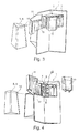
- a coffee machine 1 has a housing 2 with a discharge carriage 3 mounted height-adjustable thereon, which is connected via a supply line 4 to a storage container 5, in particular to a milk container 6.
- the feed line 4 now has a first coupling point 7 and a second coupling point 8, between which a flexible hose 9 connecting the two coupling points 7, 8 is arranged.
- the first coupling point 7 is detachably fixed to the housing 2 and at the same time fluidly connected to the reservoir 5, whereas the second coupling point 8 detachably fixed to the discharge carriage 3 and at the same time fluidly connectable with an attachable to the output slide milk / coffee spout 10 (see. Fig. 4 ).
- the feed line 4 is cleverly arranged behind the milk / coffee spout 10 and thus not visible to a user of the coffee machine 1, whereby a high-quality overall aesthetic impression can be achieved.
- a panel 11 which covers the milk / coffee spout 10 in the closed state, said panel 11 can be hinged to the output slide 3, for example by means of a hinge 12.
- the first coupling point 7 via a guide 13 on the housing 2 of the coffee machine 1 is fixed.
- the guide 13 may be, for example, a corresponding opening in the housing 2.
- the second coupling point 8 can also be fixed on the discharge carriage 3 via a guide 13 ', in which case the guide 13' is designed in the manner of a receiving opening 14 on the discharge carriage 3.
- the second coupling point 8 can thus be fixed on the discharge carriage 3.
- a disassembly of the second coupling point 8 is characterized comparatively easy. If the second coupling point 8 of the feed line 4 is mounted on the discharge carriage 3, it is possible from the front (cf. Fig.
- first coupling point 7 of the reservoir 5 can be inserted into a corresponding opening in the housing 2 of the coffee machine 1, wherein in the inserted state of the reservoir 5, ie the milk container 6, via a connection 15 fluidly connected to the first coupling point 7 is.
- the entire supply line 4 is arranged in the discharge tray 3 behind the milk / coffee spout 10 and in particular behind a panel 11, so that the entire supply line 4 is not visible when using the coffee machine 1 for a user.
- the second coupling point 8 can be pulled out of the guide 13 'or the receiving opening 14 of the delivery carriage 3.
- the first coupling point 7 can also be detached from the housing 2, for example by simply pulling it out. This is according to the Fig. 6 shown. In this state, the entire supply line 4, ie the first coupling point 7, the second coupling point 8 and the two coupling points 7, 8 connecting hose 9 removed and can be easily cleaned separately. Of course, even a separation of the tube 9 of the two coupling points 7, 8 conceivable.
- the feed line 4 together with coupling points 7, 8 and hose 9 and the milk / coffee spout 10 can be easily removed for cleaning purposes, so that all components in contact with milk can be removed for cleaning. Due to the construction according to the invention, the feed line 4 is not visible during operation of the coffee machine 1, whereby a high aesthetic overall impression can be achieved.
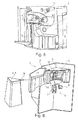
- FIGS. 7 to 10 show representations of a second embodiment of the invention.
- FIG. 1 in principle comparable front side of the second embodiment according to FIG. 7 also applies a user in an upper area of the user Coffee machine 1 and its housing 2 arranged aperture 11 to below a height-adjustable milk / coffee spout 10 protrudes.
- a part of a milk container 6 can be seen as a storage container, which is pushed laterally into the housing 2.
- FIG. 7 represents the milk / coffee spout 10 in an upper operating position, it is in FIG. 9 removed from the housing 2.
- To the left of the discharge carriage 3 and immediately below the diaphragm 11 is a recess 13 which, like the delivery carriage 3, is covered by the milk / coffee spout 10 in its mounted state. In the recess 13 is just a front portion of the terminal 15 of the milk container 6 can be seen.
- coffee feed lines 17, which supply the milk / coffee spout 10 with coffee, hot water and / or superheated steam, are also visible in the discharge carriage 3.
- FIG. 8 shows a milk / coffee spout 10 according to the second embodiment from its back.
- the supply line 4 is mounted in its cuboid housing 18. It is composed of the first end 7, the flexible hose 9 and the second end 8 (see also FIG. 10 ).
- the first end 7 as the first coupling point of the feed line 4 protrudes thorn-shaped out of the housing 18 of the milk / coffee spout 10 and thus stands back from the removed milk / coffee spout 10 back.
- the first end 7 has a horizontally oriented tubular milk connection 19, to which the milk container 6 can couple.
- the first end 7 is held releasably in the housing 18, so that it can be removed as part of the supply line.
- it is also mounted vertically movable within the housing 18. This is done with a magnet on a in FIG. 7 hidden metallic surface fixed in the housing 18.
- the flexible, S-shaped bent hose 9 connects, which extends from an upper position of the first end 7 down to the second end 8.
- the second end 8 as a second coupling point of the supply line 4 is inserted in a receiving shaft 14 ', which has on the underside of the housing 18 unrecognizable openings.
- the second end 8 comprises two vertically standing overflow domes 20 which are connected to the hose 9 and the first end 7 are fluidly connected.
- the second end 8 includes two in FIG. 8 unrecognizable coffee spouts 21 (cf. FIG. 10 ) which are in fluid communication with a coffee port 22. He communicates in the mounted state of the milk / coffee spout 10 with the coffee supply lines 17 according to FIG. 9 ,
- FIG. 10 Finally, all milk-carrying and therefore removable components of the automatic coffee machine 1 are: these are, on the one hand, the milk container 6 with its connection 15 and, on the other hand, the supply line 4 consisting of the first end 7, the flexible tube 9 and the second end 8.
- the milk container 6 is first removed laterally from the housing 2.
- the plug connection between the milk container 6 and its connection 15 and the milk connection 19 of the first end 7 dissolves.
- the milk / coffee spout 10 is moved downwards into its lowest position, so that it is positioned completely below the aperture 11.
- the output slide 3 receives the in FIG. 9 shown position. Now the milk / coffee spout 10 can be deducted from the output slide 3 towards the user, what the fixed aperture 11 does not prevent him. In this case, the fluidic connection between the coffee connections 22 and the coffee supply lines 17 is released.
- the user receives approximately the view according to FIG. 8 ,
- the feed line 4 to be cleaned is convenient in his field of vision, which he can also move regardless of the location of the coffee machine 1 in an optionally better-lit region.
- the first end 7 is released from its position within the housing 18 against the magnetic force.
- the flexible hose can be largely removed from the housing 18.
- the second end 8 is removed from the receiving well 14 by being withdrawn from the receiving well 14 'in a vertical upward direction.
- the first end or the first coupling point 7 and the housing 18 of the milk / coffee spout 10 and the Aperture 11 manages to make the feed line 4 and its coupling points for its first and second ends 7, 8 hidden from the user or not visible.
- the vertical position of the first end 7 coincides with the height of the connection 15 of the milk container 6 and the lowest position of the discharge carriage 3 together.
- the horizontal position of the first end 7 can be determined by the width of the outlet carriage 3, next to which it must protrude into the opening 13. For both the output slide 3 and the opening 13 are covered by the housing 18 of the milk / coffee spout 10.
Landscapes
- Engineering & Computer Science (AREA)
- Food Science & Technology (AREA)
- Apparatus For Making Beverages (AREA)
Abstract
Die Erfindung betrifft einen Kaffeeautomat (1) mit einem Gehäuse (2) und einem daran höhenverstellbar gelagerten Ausgabeschlitten (3), der über eine Zulaufleitung (4) mit einem Vorratsbehälter (5), insbesondere mit einem Milchbehälter (6), verbunden ist. Erfindungswesentlich ist dabei, dass die Zulaufleitung (4) eine erste Koppelstelle (7) und eine zweite Koppelstelle (8) aufweist sowie einen die erste und zweite Koppelstelle (7,8) verbindenden flexiblen Schlauch (9), wobei die erste Koppelstelle (7) lösbar fest am Gehäuse (2) und fluidleitend mit dem Vorratsbehälter (5) und die zweite Koppelstelle (8) lösbar fest mit dem Ausgabeschlitten (3) und fluidleitend mit einem auf den Ausgabeschlitten (3) aufsteckbaren Milch-/Kaffeeauslauf (10) verbindbar ist, so dass der Vorratsbehälter (5), die Zulaufleitung (4) samt Koppelstellen (7,8) und der Milch-/Kaffeeauslauf (10) zu Reinigungszwecken vom Kaffeeautomaten (1) abnehmbar sind. Hierdurch kann eine optisch ansprechende und leicht zu montierende bzw. demontierende Milchleitung vorgesehen werden.The invention relates to a coffee machine (1) having a housing (2) and an output carriage (3) mounted height-adjustable thereon, which is connected via a feed line (4) to a storage container (5), in particular to a milk container (6). It is essential to the invention that the supply line (4) has a first coupling point (7) and a second coupling point (8) and a flexible hose (9) connecting the first and second coupling points (7, 8), wherein the first coupling point (7) releasably fixed to the housing (2) and fluid-conducting with the reservoir (5) and the second coupling point (8) detachably fixed to the discharge carriage (3) and fluid-conducting with a on the output slide (3) attachable milk / coffee spout (10) is connectable , so that the storage container (5), the supply line (4) together with coupling points (7,8) and the milk / coffee spout (10) for cleaning purposes of the coffee machine (1) are removable. As a result, a visually appealing and easy to assemble or disassemble milk line can be provided.
Description
Die vorliegende Erfindung betrifft einen Kaffeeautomaten mit einem Gehäuse und einem daran höhenverstellbar gelagerten Ausgabeschlitten gemäß dem Oberbegriff des Anspruchs 1.The present invention relates to a coffee machine with a housing and a height adjustable mounted on this output carriage according to the preamble of
Aus der
Aus der
Nachteilig bei den aus dem Stand der Technik bekannten Kaffeeautomaten ist oftmals, dass zur Realisierung eines optisch ansprechenden Erscheinungsbildes Zulaufleitungen, wie beispielsweise ein Milchschlauch, nicht sichtbar verlegt sein sollen. Das nicht sichtbare Verlegen wiederum bedeutet jedoch auf der anderen Seite einen vergleichsweise hohen Montage- und Demontageaufwand, der für jede Reinigung der Zulaufleitung, insbesondere einer Milch führenden Leitung, getätigt werden muss.A disadvantage of the coffee machines known from the prior art is often that for the realization of a visually appealing appearance feed lines, such as a milk hose, should not be installed visible. The invisible laying, however, on the other hand means a comparatively high assembly and disassembly effort, which must be made for each cleaning of the supply line, in particular a milk leading line.
Die vorliegende Erfindung beschäftigt sich daher mit dem Problem, für einen Kaffeeautomaten der gattungsgemäßen Art eine verbesserte oder zumindest eine alternative Ausführungsform anzugeben, die insbesondere die aus dem Stand der Technik bekannten Nachteile nicht mehr aufweist.The present invention therefore deals with the problem of providing for a coffee machine of the generic type an improved or at least one alternative embodiment, which in particular no longer has the disadvantages known from the prior art.
Dieses Problem wird erfindungsgemäß durch die Gegenstände der unabhängigen Ansprüche 1 und 2 gelöst. Vorteilhafte Ausführungsformen sind Gegenstand der abhängigen Ansprüche.This problem is solved according to the invention by the subject-matter of
Die vorliegende Erfindung beruht auf dem allgemeinen Gedanken, bei einem an sich bekannten Kaffeeautomaten mit einem Gehäuse und einem daran höhenverstellbar gelagerten Ausgabeschlitten sämtliche mit Milch in Kontakt tretende Komponenten zwischen dem Gehäuse und dem Ausgabeschlitten so auszubilden, dass diese vergleichsweise einfach vom Kaffeeautomaten abgenommen und dadurch auch vergleichsweise einfach gereinigt werden können. Hierzu weist eine Zulaufleitung eine erste Koppelstelle sowie eine zweite Koppelstelle auf, zwischen welchen ein die beiden Koppelstellen verbindender, flexibler Schlauch angeordnet ist. Die erste Koppelstelle ist bei einer ersten Ausführungsform nach Anspruch 1 lösbar fest am Gehäuse und zugleich fluidleitend mit einem Vorratsbehälter verbindbar, wogegen die zweite Koppelstelle lösbar fest mit dem Ausgabeschlitten und zudem fluidleitend mit einem auf den Ausgabeschlitten aufsteckbaren Milch-/Kaffeeauslauf verbindbar ist. Auch bei der zweiten Ausführungsform nach Anspruch 2 ist die erste Koppelstelle lösbar fest am Gehäuse und zugleich fluidleitend mit einem Vorratsbehälter verbindbar. Die zweite Koppelstelle jedoch ist lösbar fest mit einem auf den Ausgabeschlitten aufsteckbaren Milch-/Kaffeeauslauf und zudem fluidleitend mit dem Ausgabeschlitten verbindbar. "Lösbar fest" bedeutet, dass die Verbindung der Lage nach fest definiert, aber manuell lösbar ist. Nach der Herstellung eines Kaffeemischgetränks, wie beispielsweise eines Cappuccinos, können somit der Vorratsbehälter, die Zulaufleitung mit ihren beiden Koppelstellen sowie der Milch-/Kaffeeauslauf zu Reinigungszwecken einfach vom Kaffeeautomaten abgenommen werden. Eine aufwändige Demontage der Zulaufleitung, wie bei bisherigen Kaffeeautomaten erforderlich, kann hierdurch entfallen. Auch ist bei den erfindungsgemäßen Kaffeeautomaten ein separates und damit vergleichsweise einfaches Reinigen sämtlicher mit Milch in Berührung kommender Komponenten des Kaffeeautomaten möglich, da diese einfach und mit geringem Aufwand abbaubar sind und dadurch beispielsweise in einer Spülmaschine wie herkömmliches Geschirr gereinigt werden können.The present invention is based on the general idea, in a conventional coffee machine with a housing and a height adjustable mounted discharge sled all milk coming into contact components between the housing and the output slide in such a way that they are relatively easily removed from the coffee machine and thus can be cleaned comparatively easily. For this purpose, a supply line to a first coupling point and a second coupling point, between which a two coupling points connecting, flexible hose is arranged. The first coupling point is in a first embodiment according to claim 1 detachably fixed to the housing and at the same time fluidly connected to a reservoir, whereas the second coupling point releasably fixed to the output slide and also fluidly connected to a plug-on on the output slide milk / coffee spout is connectable. Also in the second embodiment according to
Bei einer vorteilhaften Weiterbildung der erfindungsgemäßen Lösung ist die Zulaufleitung von außen nicht sichtbar hinter einer Blende und verdeckt durch den Milch-/Kaffeeauslauf, insbesondere hinter ihm bzw. auf seiner Rückseite angeordnet. Die Anordnung auf der Rückseite des Milch-/Kaffeeauslaufs umfasst auch eine Konstruktion, bei der die Zuleitung von einer Rückseite des Milch-/Kaffeeauslaufs aus in ihm bzw. in seinem Gehäuse (de-)montierbar ist. Hierdurch ist es möglich, einen optisch äußerst ansprechenden Gesamteindruck zu erzeugen, da die Zulaufleitung für die Milch zum Milch-/Kaffeeauslauf für einen Benutzer des Kaffeeautomaten nicht sichtbar ist. Durch den abnehmbaren und insbesondere aufsteckbaren Milch-/Kaffeeauslauf ist es möglich, die Zulaufleitung mit ihren beiden Koppelstellen einfach am Ausgabeschlitten am Gehäuse bzw. am Milch-/Kaffeeauslauf zu montieren bzw. von diesem wieder abzunehmen, ohne dass hierfür eine aufwendige Demontage erfolgen muss. Durch das einfache Aufstecken des Milch-/Kaffeeauslaufs und damit auch durch ein einfaches Abziehen desselben werden die dahinterliegenden Bereiche bzw. seine Rückseite leicht zugänglich, wodurch insbesondere ein bisher unter Umständen erforderliches blindes Montieren bzw. "Durchfädeln" vermieden werden kann. Die Anordnung der Zulaufleitung auf der Rückseite des Milch-/Kaffeeauslaufs erleichtert die (De-)Montage der Zulaufleitung zusätzlich, da der Benutzer sie getrennt oder gar entfernt vom Kaffeevollautomaten beispielsweise bei ihm geeigneter erscheinenden Lichtverhältnissen manipulieren kann. Die Blende kann dabei auf den Milch-/Kaffeeauslauf bzw. auf den Ausgabeschlitten aufgesteckt oder aber mittels eines Scharniers am Ausgabeschlitten gelagert sein. Rein theoretisch ist selbstverständlich auch eine einstückige bzw. einteilige Ausbildung der Blende mit dem Milch-/Kaffeeauslauf denkbar.In an advantageous embodiment of the solution according to the invention, the supply line is not visible from the outside behind a panel and hidden by the milk / coffee spout, in particular behind him or arranged on its back. The arrangement on the back of the milk / coffee spout also includes a construction in which the supply line can be (de-) mounted from a back side of the milk / coffee spout in or in its housing. This makes it possible to produce a visually extremely appealing overall impression, since the feed line for the milk to the milk / coffee spout for a user of the coffee machine is not visible. Due to the removable and especially attachable milk / coffee spout, it is possible to easily mount the supply line with its two coupling points on the output slide on the housing or the milk / coffee spout or remove it again, without the need for a costly disassembly. Due to the simple plugging of the milk / coffee spout and thus also by a simple removal of the underlying areas or its back are easily accessible, which in particular a hitherto possibly required blind mounting or "threading" can be avoided. The arrangement of the feed line on the back of the milk / coffee spout also facilitates the (dis) assembly of the feed line, as the user can manipulate them separately or even remotely from the coffee machine, for example, appearing suitable light conditions. The panel can be attached to the milk / coffee spout or on the output slide or stored by means of a hinge on the output slide. In theory, of course, a one-piece or one-piece design of the aperture with the milk / coffee spout is conceivable.
Zweckmäßig ist die erste Koppelstelle über eine Führung am Gehäuse des Kaffeeautomaten fixierbar, wobei die Führung beispielsweise in der Art einer Öffnung ausgebildet sein kann. Eine derartige Führung erleichtert eine Montage bzw. Demontage der ersten Koppelstelle am Gehäuse erheblich, da sowohl die Montage als auch die Demontage durch eine einfache Schiebe- oder Steckbewegung realisiert werden können. In gleicher oder ähnlicher Weise kann selbstverständlich auch die zweite Koppelstelle am Ausgabeschlitten bzw. am Milch-/Kaffeeauslauf fixiert werden, wobei an diesem zusätzlich eine Aufnahmeöffnung bzw. ein Aufnahmeschacht zur Aufnahme der zweiten Koppelstelle vorgesehen sein kann.Suitably, the first coupling point is fixable via a guide on the housing of the coffee machine, wherein the guide may be formed, for example, in the manner of an opening. Such a guide facilitates assembly and disassembly of the first coupling point on the housing considerably, since both the assembly and disassembly can be realized by a simple sliding or plugging movement. In the same or similar manner, of course, the second coupling point can be fixed to the output slide or the milk / coffee spout, in addition to this a receiving opening or a receiving shaft for receiving the second coupling point may be provided.
Weitere wichtige Merkmale und Vorteile der Erfindung ergeben sich aus den Unteransprüchen, aus den Zeichnungen und aus der zugehörigen Figurenbeschreibung anhand der Zeichnungen.Other important features and advantages of the invention will become apparent from the dependent claims, from the drawings and from the associated figure description with reference to the drawings.
Es versteht sich, dass die vorstehend genannten und die nachstehend noch zu erläuternden Merkmale nicht nur in der jeweils angegebenen Kombination, sondern auch in anderen Kombinationen oder in Alleinstellung verwendbar sind, ohne den Rahmen der vorliegenden Erfindung zu verlassen.It is understood that the features mentioned above and those yet to be explained below can be used not only in the particular combination given, but also in other combinations or in isolation, without departing from the scope of the present invention.
Bevorzugte Ausführungsbeispiele der Erfindung sind in den Zeichnungen dargestellt und werden in der nachfolgenden Beschreibung näher erläutert, wobei sich gleiche Bezugszeichen auf gleiche oder ähnliche oder funktional gleiche Bauteile beziehen.Preferred embodiments of the invention are illustrated in the drawings and will be described in more detail in the following description, wherein like reference numerals refer to the same or similar or functionally identical components.
Dabei zeigen, jeweils schematisch:
- Fig. 1
- eine erste Ausgestaltungsform eines erfindungsgemäßen Kaffeeautomaten mit angeschlossenem Vorratsbehälter und geschlossener, einen Milch-/Kaffeeauslauf überdeckenden Blende,
- Fig. 2
- eine Darstellung wie in
Fig. 1 , jedoch bei entnommenem Vorratsbehälter, - Fig. 3
- eine Darstellung wie in
Fig. 2 , jedoch bei geöffneter Blende, - Fig. 4
- eine Darstellung wie in
Fig. 3 , jedoch bei entnommenem Milch-/Kaffeeauslauf, - Fig. 5
- eine Detaildarstellung des Ausgabeschlittens,
- Fig. 6
- eine Darstellung wie in
Fig. 4 , jedoch mit entnommener Zulaufleitung, - Fig. 7
- eine zweite Ausgestaltungsform eines erfindungsgemäßen Kaffeeautomaten mit angeschlossenem Vorratsbehälter und einer einen Milch-/Kaffeeauslauf überdeckenden Blende,
- Fig. 8
- einen Milch-/Kaffeeauslauf von seiner Rückseite aus,
- Fig. 9
- eine Darstellung wie in
Fig. 7 , jedoch bei abgenommenem Milch-/Kaffeeauslauf, - Fig.10
- Detaildarstellungen des Vorratsbehälters und der Zulaufleitung als milchführende Bauteile.
- Fig. 1
- A first embodiment of a coffee machine according to the invention with connected storage container and closed, a milk / coffee spout overlapping aperture
- Fig. 2
- a representation like in
Fig. 1 , but with removed reservoir, - Fig. 3
- a representation like in
Fig. 2 , but with the aperture open, - Fig. 4
- a representation like in
Fig. 3 , but with the milk / coffee spout removed, - Fig. 5
- a detailed representation of the output carriage,
- Fig. 6
- a representation like in
Fig. 4 , but with removed feed line, - Fig. 7
- A second embodiment of a coffee machine according to the invention with connected storage container and a milk / coffee spout overlapping aperture,
- Fig. 8
- a milk / coffee spout from its back,
- Fig. 9
- a representation like in
Fig. 7 , but with removed milk / coffee spout, - Figure 10
- Details of the storage container and the supply line as milk-carrying components.
Entsprechend der
Betrachtet man die
Um eine Montage und Demontage der Zulaufleitung 4 weiter zu erleichtern, ist die erste Koppelstelle 7 über eine Führung 13 am Gehäuse 2 des Kaffeeautomaten 1 fixierbar. Die Führung 13 kann dabei beispielsweise eine entsprechende Öffnung im Gehäuse 2 sein. Die zweite Koppelstelle 8 ist ebenfalls über eine Führung 13' am Ausgabeschlitten 3 fixierbar, wobei in diesem Fall die Führung 13' in der Art einer Aufnahmeöffnung 14 am Ausgabeschlitten 3 ausgebildet ist. Durch ein einfaches Einschieben der zweiten Koppelstelle 8 in die Aufnahmeöffnung 14 lässt sich somit die zweite Koppelstelle 8 am Ausgabeschlitten 3 fixieren. Auch eine Demontage der zweiten Koppelstelle 8 ist dadurch vergleichsweise einfach möglich. Ist die zweite Koppelstelle 8 der Zulaufleitung 4 am Ausgabeschlitten 3 montiert, so kann von vorne (vgl.
Mittels des erfindungsgemäßen Kaffeeautomaten 1 lässt sich eine Reinigung desselben, insbesondere eine Reinigung der Zulaufleitung 4, besonders einfach bewerkstelligen, was im Folgenden genauer beschrieben wird. Zudem ist die gesamte Zulaufleitung 4 im Ausgabeschlitten 3 hinter dem Milch-/Kaffeeauslauf 10 und insbesondere auch hinter einer Blende 11 angeordnet, so dass die gesamte Zulaufleitung 4 bei der Benutzung des Kaffeeautomaten 1 für einen Benutzer nicht sichtbar ist.By means of the
Die Demontage der Zulaufleitung 4 bzw. der mit Milch in Berührung kommenden Komponenten des Kaffeeautomaten 1 erfolgt dabei wie folgt:
- Zunächst befindet sich
der Kaffeeautomat 1 in dem gemäß derFig. 1 dargestellten Zustand, also beispielsweise am Ende eines Kaffeezubereitungsprozesses. Gemäß derFig. 2 wird dann der Vorratsbehälter 5, d.h.der Milchbehälter 6,aus dem Gehäuse 2 desKaffeeautomaten 1 entfernt, wodurch derAnschluss 15 des Vorratsbehälters 5 von der ersten Koppelstelle 7der Zulaufleitung 4 getrennt wird. Gemäß derFig. 3 wird im sich daran anschließenden Verfahrensschritt dieBlende 11 geöffnet und dadurch ein Zugang zum Milch-/Kaffeeauslauf 10 freigegeben, welcher nun einfach, wie inFig. 4 dargestellt ist,vom Ausgabeschlitten 3 desKaffeeautomaten 1 abgezogen werden kann. Hierbei löst sich der Milch-/Kaffeeauslauf 10 von der zweiten Koppelstelle 8, ebenso wievon einem Wasserzulauf 16.Die zweite Koppelstelle 8 bzw.der Wasserzulauf 16 besitzen dabei Nippel mit entsprechenden O-Ring-Dichtungen, welche dicht in entsprechende Öffnungen des Milch-/Kaffeeauslaufs 10 in bekannter Weise eingreifen.
- First, the
coffee machine 1 is in the according to theFig. 1 illustrated state, so for example at the end of a coffee preparation process. According to theFig. 2 Then, the reservoir 5, ie themilk container 6, removed from thehousing 2 of thecoffee machine 1, whereby theterminal 15 of the reservoir 5 is separated from thefirst coupling point 7 of thefeed line 4. According to theFig. 3 In the subsequent process step, theaperture 11 is opened and thereby an access to the milk /coffee spout 10 is released, which is now easy, as inFig. 4 is shown, can be deducted from theoutput slide 3 of thecoffee machine 1. This triggers The milk /coffee spout 10 from thesecond coupling point 8, as well as awater inlet 16. Thesecond coupling point 8 and thewater inlet 16 have nipples with corresponding O-ring seals, which closely into corresponding openings of the milk /coffee spout 10 intervene in a known manner.
Ist der Milch-/Kaffeeauslauf 10 vom Ausgabeschlitten 3 abgezogen, so kann die zweite Koppelstelle 8 aus der Führung 13' bzw. der Aufnahmeöffnung 14 des Ausgabeschlittens 3 herausgezogen werden. Gleichzeitig oder anschließend kann auch die erste Koppelstelle 7 vom Gehäuse 2, beispielsweise durch ein einfaches Herausziehen, gelöst werden. Dies ist gemäß der
Ein Zusammenbau erfolgt in umgekehrter Reihenfolge, so dass zunächst die erste Koppelstelle 7 in die Führung 13 am Gehäuse 2 eingeschoben wird, woraufhin die zweite Koppelstelle 8 in die Führung 13', d.h. in die Aufnahmeöffnung 14, des Ausgabeschlittens 3, eingeschoben wird. Die Zulaufleitung 4 ist somit bereits montiert. Anschließend kann der Milch-/Kaffeeauslauf 10 auf den Ausgabeschlitten 3 aufgesteckt werden. Nunmehr muss nur noch die Blende 11 geschlossen und der Milchbehälter 6 in das Gehäuse 2 eingeschoben und über den Anschluss 15 mit der ersten Koppelstelle 7 verbunden werden.An assembly takes place in the reverse order, so that first the
Mit dem erfindungsgemäßen Kaffeeautomaten 1 lässt sich insbesondere die Zulaufleitung 4 samt Koppelstellen 7, 8 und Schlauch 9 sowie der Milch-/Kaffeeauslauf 10 einfach zu Reinigungszwecken entnehmen, so dass sämtliche mit Milch in Berührung stehende Komponenten zur Reinigung entnommen werden können. Durch die erfindungsgemäße Konstruktion ist auch die Zulaufleitung 4 während des Betriebs des Kaffeeautomaten 1 nicht sichtbar, womit ein hoher ästhetischer Gesamteindruck erzielt werden kann.With the
Während
An das erste Ende 7 schließt sich der flexible, S-förmig gebogene Schlauch 9 an, der von einer oberen Position des ersten Endes 7 hinab zum zweiten Ende 8 reicht. Das zweite Ende 8 als zweite Kopplungsstelle der Zulaufleitung 4 steckt in einem Aufnahmeschacht 14', der an der Unterseite des Gehäuses 18 nicht erkennbare Durchbrüche aufweist. Das zweite Ende 8 umfasst zwei vertikal stehende Überlaufdome 20, die mit dem Schlauch 9 und dem ersten Ende 7 fluidisch verbunden sind. Außerdem umfasst das zweite Ende 8 zwei in
Zur Demontage des Milch-/Kaffeeauslaufs 10, beispielsweise zu Reinigungszwecken der milchführenden Bauteile, wird zunächst der Milchbehälter 6 seitlich aus dem Gehäuse 2 entnommen. Dabei löst sich die Steckverbindung zwischen dem Milchbehälter 6 bzw. seinem Anschluss 15 und dem Milchanschluss 19 des ersten Endes 7. Anschließend wird der Milch-/Kaffeeauslauf 10 in seine tiefste Stellung abwärts verfahren, so dass er vollständig unterhalb der Blende 11 positioniert ist. Dabei erhält der Ausgabeschlitten 3 die in
Mit einer 180°-Drehung des Milch-/Kaffeeauslaufs 10 erhält der Benutzer etwa die Ansicht gemäß
Durch eine geeignete Dimensionierung des Milchbehälters 6, des ersten Endes bzw. der ersten Kopplungsstelle 7 und des Gehäuses 18 des Milch-/Kaffeeauslaufs 10 sowie der Blende 11 gelingt es, die Zulaufleitung 4 und ihre Kopplungsstellen für ihr erstes und zweites Ende 7, 8 für den Benutzer verdeckt bzw. nicht sichtbar zu gestalten. Dazu fällt die vertikale Position des ersten Endes 7 mit der Höhe des Anschlusses 15 des Milchbehälters 6 und die unterste Position des Ausgabeschlittens 3 zusammen. Die horizontale Position des ersten Endes 7 lässt sich durch die Breite des Auslaufschlittens 3 bestimmen, neben dem es in die Öffnung 13 ragen muss. Denn sowohl der Ausgabeschlitten 3 als auch die Öffnung 13 werden vom Gehäuse 18 des Milch-/Kaffeeauslaufs 10 verdeckt. Je weiter entfernt von einer vertikalen Symmetrieachse der Ansichtsfront die Aussparung 13 liegt, umso breiter wird das Gehäuse 18 ausfallen. Je näher es der Symmetrieachse rückt, umso weiter muss der Milchbehälter 6 in das Gehäuse 2 hineinragen, womit er stärker durch den Kaffeevollautomaten 1 erwärmt werden könnte. Eine bezüglich der kartesischen Koordinatenachsen schräge Anordnung des ersten Endes 7 zur Erfüllung der unterschiedlichen geometrischen Anforderungen würde eine ebenso schräge (De-) Montagerichtung des Milch-/Kaffeeauslaufs 10 erfordern. Sie kann jedoch für einen Benutzer schwerer nachvollziehbar sein, solange er die im Wesentlichen vertikale Gerätefront als Bezugsebene für seine Betätigungsrichtungen betrachtet.By a suitable dimensioning of the
- 11
- KaffeeautomatCoffeemaker
- 22
- Gehäusecasing
- 33
- Ausgabeschlittenoutput slide
- 44
- Zulaufleitungsupply line
- 55
- Vorratsbehälterreservoir
- 66
- Milchbehältermilk container
- 77
- erste Koppelstellefirst coupling point
- 88th
- zweite Koppelstellesecond coupling point
- 99
- Schlauchtube
- 1010
- Milch-/KaffeeauslaufMilk / coffee dispenser
- 1111
- Blendecover
- 1212
- Scharnierhinge
- 13, 13'13, 13 '
- Führungguide
- 14, 14'14, 14 '
- Aufnahmeadmission
- 1515
- Anschlussconnection
- 1616
- Wasserzulaufwater supply
- 1717
- Kaffeezuleitungencoffee leads
- 1818
- Gehäusecasing
- 1919
- Milchanschlussmilk connection
- 2020
- ÜberlaufdomÜberlaufdom
- 2121
- Kaffeeauslaufcoffee spout
- 2222
- Kaffeeanschlusscoffee connection
Claims (10)
Applications Claiming Priority (1)
| Application Number | Priority Date | Filing Date | Title |
|---|---|---|---|
| DE102014224085.9A DE102014224085A1 (en) | 2014-11-26 | 2014-11-26 | Coffeemaker |
Publications (2)
| Publication Number | Publication Date |
|---|---|
| EP3025624A1 true EP3025624A1 (en) | 2016-06-01 |
| EP3025624B1 EP3025624B1 (en) | 2018-09-26 |
Family
ID=54364163
Family Applications (1)
| Application Number | Title | Priority Date | Filing Date |
|---|---|---|---|
| EP15192270.5A Active EP3025624B1 (en) | 2014-11-26 | 2015-10-30 | Coffee machine |
Country Status (2)
| Country | Link |
|---|---|
| EP (1) | EP3025624B1 (en) |
| DE (1) | DE102014224085A1 (en) |
Citations (4)
| Publication number | Priority date | Publication date | Assignee | Title |
|---|---|---|---|---|
| EP1639926A1 (en) | 2004-09-24 | 2006-03-29 | Fianara International B.V. | Coffee apparatus with a height-adustable collecting bowl |
| WO2009027054A1 (en) | 2007-08-24 | 2009-03-05 | Miele & Cie. Kg | Beverage-making machine having a housing and a height-adjustable tap unit mounted therein and tap method |
| DE202008008257U1 (en) * | 2008-06-19 | 2009-10-29 | Wik Far East Ltd. | coffee machine |
| EP2875761A1 (en) * | 2013-11-20 | 2015-05-27 | BSH Hausgeräte GmbH | Coffee machine |
-
2014
- 2014-11-26 DE DE102014224085.9A patent/DE102014224085A1/en not_active Withdrawn
-
2015
- 2015-10-30 EP EP15192270.5A patent/EP3025624B1/en active Active
Patent Citations (4)
| Publication number | Priority date | Publication date | Assignee | Title |
|---|---|---|---|---|
| EP1639926A1 (en) | 2004-09-24 | 2006-03-29 | Fianara International B.V. | Coffee apparatus with a height-adustable collecting bowl |
| WO2009027054A1 (en) | 2007-08-24 | 2009-03-05 | Miele & Cie. Kg | Beverage-making machine having a housing and a height-adjustable tap unit mounted therein and tap method |
| DE202008008257U1 (en) * | 2008-06-19 | 2009-10-29 | Wik Far East Ltd. | coffee machine |
| EP2875761A1 (en) * | 2013-11-20 | 2015-05-27 | BSH Hausgeräte GmbH | Coffee machine |
Also Published As
| Publication number | Publication date |
|---|---|
| DE102014224085A1 (en) | 2016-06-02 |
| EP3025624B1 (en) | 2018-09-26 |
Similar Documents
| Publication | Publication Date | Title |
|---|---|---|
| DE102010007143B4 (en) | Coffee machine with a foaming device and means for cleaning the foaming device and a milk suction line and method for rinsing the milk suction line | |
| EP1715780B1 (en) | Coffee machine comprising a height-adjustable spout | |
| DE102006043903B3 (en) | Coffee machine, to dispense coffee in cup portions, has a hot brew outflow with a relative movement against the steam/foamed milk outflow | |
| EP2441360B1 (en) | Electric beverage preparation machine | |
| DE102007010318A1 (en) | Removable nozzle cover for a fluid dispenser | |
| EP1776027B1 (en) | Beverage preparer and dispensing device for a beverage preparer | |
| DE202009013064U1 (en) | Coffee / espresso machine with a milk froth maker for cappuccino | |
| EP2875761B1 (en) | Coffee machine | |
| EP2807964B1 (en) | Milk foaming device, coffee machine, system and cleaning method | |
| DE202009004756U1 (en) | coffee machine | |
| EP2323522B1 (en) | Beverage-dispensing appliance | |
| EP2710939B1 (en) | Fully automatic coffee maker with flexible conduit | |
| EP3025624B1 (en) | Coffee machine | |
| EP2236061A1 (en) | Automatic beverage dispenser | |
| DE4005348A1 (en) | COFFEE MACHINE | |
| EP3648642B1 (en) | Milk module for generating milk foam or milk beverages, preferably for installing into a coffee machine | |
| EP3369352B1 (en) | Drink preparation device | |
| DE102018200824B3 (en) | Pull-out hose device with fluid connection and sanitary shower | |
| EP3339521B1 (en) | Shower attachment for a wc | |
| DE102020201936A1 (en) | Coffee machine with a steam lance for frothing milk | |
| EP3138449B1 (en) | Coffee machine | |
| DE202004020916U1 (en) | Espresso machine has spout whose height can be adjusted, baffle plate being mounted above this, through which coffee falls from brewing chamber | |
| DE102015205121B4 (en) | Milk frother for hot drinks machines and hot drinks machine with a milk frother | |
| DE102004046456B4 (en) | Coffee machine with height-adjustable spout | |
| DE102007010793B4 (en) | shower arrangement |
Legal Events
| Date | Code | Title | Description |
|---|---|---|---|
| PUAI | Public reference made under article 153(3) epc to a published international application that has entered the european phase |
Free format text: ORIGINAL CODE: 0009012 |
|
| AK | Designated contracting states |
Kind code of ref document: A1 Designated state(s): AL AT BE BG CH CY CZ DE DK EE ES FI FR GB GR HR HU IE IS IT LI LT LU LV MC MK MT NL NO PL PT RO RS SE SI SK SM TR |
|
| AX | Request for extension of the european patent |
Extension state: BA ME |
|
| 17P | Request for examination filed |
Effective date: 20161201 |
|
| RBV | Designated contracting states (corrected) |
Designated state(s): AL AT BE BG CH CY CZ DE DK EE ES FI FR GB GR HR HU IE IS IT LI LT LU LV MC MK MT NL NO PL PT RO RS SE SI SK SM TR |
|
| 17Q | First examination report despatched |
Effective date: 20170719 |
|
| GRAP | Despatch of communication of intention to grant a patent |
Free format text: ORIGINAL CODE: EPIDOSNIGR1 |
|
| INTG | Intention to grant announced |
Effective date: 20180502 |
|
| GRAS | Grant fee paid |
Free format text: ORIGINAL CODE: EPIDOSNIGR3 |
|
| GRAA | (expected) grant |
Free format text: ORIGINAL CODE: 0009210 |
|
| AK | Designated contracting states |
Kind code of ref document: B1 Designated state(s): AL AT BE BG CH CY CZ DE DK EE ES FI FR GB GR HR HU IE IS IT LI LT LU LV MC MK MT NL NO PL PT RO RS SE SI SK SM TR |
|
| REG | Reference to a national code |
Ref country code: GB Ref legal event code: FG4D Free format text: NOT ENGLISH |
|
| REG | Reference to a national code |
Ref country code: CH Ref legal event code: EP |
|
| REG | Reference to a national code |
Ref country code: AT Ref legal event code: REF Ref document number: 1045015 Country of ref document: AT Kind code of ref document: T Effective date: 20181015 |
|
| REG | Reference to a national code |
Ref country code: IE Ref legal event code: FG4D Free format text: LANGUAGE OF EP DOCUMENT: GERMAN |
|
| REG | Reference to a national code |
Ref country code: DE Ref legal event code: R096 Ref document number: 502015006057 Country of ref document: DE |
|
| REG | Reference to a national code |
Ref country code: FR Ref legal event code: PLFP Year of fee payment: 4 |
|
| REG | Reference to a national code |
Ref country code: NL Ref legal event code: MP Effective date: 20180926 |
|
| PG25 | Lapsed in a contracting state [announced via postgrant information from national office to epo] |
Ref country code: BG Free format text: LAPSE BECAUSE OF FAILURE TO SUBMIT A TRANSLATION OF THE DESCRIPTION OR TO PAY THE FEE WITHIN THE PRESCRIBED TIME-LIMIT Effective date: 20181226 Ref country code: GR Free format text: LAPSE BECAUSE OF FAILURE TO SUBMIT A TRANSLATION OF THE DESCRIPTION OR TO PAY THE FEE WITHIN THE PRESCRIBED TIME-LIMIT Effective date: 20181227 Ref country code: RS Free format text: LAPSE BECAUSE OF FAILURE TO SUBMIT A TRANSLATION OF THE DESCRIPTION OR TO PAY THE FEE WITHIN THE PRESCRIBED TIME-LIMIT Effective date: 20180926 Ref country code: NO Free format text: LAPSE BECAUSE OF FAILURE TO SUBMIT A TRANSLATION OF THE DESCRIPTION OR TO PAY THE FEE WITHIN THE PRESCRIBED TIME-LIMIT Effective date: 20181226 Ref country code: LT Free format text: LAPSE BECAUSE OF FAILURE TO SUBMIT A TRANSLATION OF THE DESCRIPTION OR TO PAY THE FEE WITHIN THE PRESCRIBED TIME-LIMIT Effective date: 20180926 Ref country code: FI Free format text: LAPSE BECAUSE OF FAILURE TO SUBMIT A TRANSLATION OF THE DESCRIPTION OR TO PAY THE FEE WITHIN THE PRESCRIBED TIME-LIMIT Effective date: 20180926 Ref country code: SE Free format text: LAPSE BECAUSE OF FAILURE TO SUBMIT A TRANSLATION OF THE DESCRIPTION OR TO PAY THE FEE WITHIN THE PRESCRIBED TIME-LIMIT Effective date: 20180926 |
|
| REG | Reference to a national code |
Ref country code: LT Ref legal event code: MG4D |
|
| PG25 | Lapsed in a contracting state [announced via postgrant information from national office to epo] |
Ref country code: AL Free format text: LAPSE BECAUSE OF FAILURE TO SUBMIT A TRANSLATION OF THE DESCRIPTION OR TO PAY THE FEE WITHIN THE PRESCRIBED TIME-LIMIT Effective date: 20180926 Ref country code: LV Free format text: LAPSE BECAUSE OF FAILURE TO SUBMIT A TRANSLATION OF THE DESCRIPTION OR TO PAY THE FEE WITHIN THE PRESCRIBED TIME-LIMIT Effective date: 20180926 Ref country code: HR Free format text: LAPSE BECAUSE OF FAILURE TO SUBMIT A TRANSLATION OF THE DESCRIPTION OR TO PAY THE FEE WITHIN THE PRESCRIBED TIME-LIMIT Effective date: 20180926 |
|
| PG25 | Lapsed in a contracting state [announced via postgrant information from national office to epo] |
Ref country code: PL Free format text: LAPSE BECAUSE OF FAILURE TO SUBMIT A TRANSLATION OF THE DESCRIPTION OR TO PAY THE FEE WITHIN THE PRESCRIBED TIME-LIMIT Effective date: 20180926 Ref country code: NL Free format text: LAPSE BECAUSE OF FAILURE TO SUBMIT A TRANSLATION OF THE DESCRIPTION OR TO PAY THE FEE WITHIN THE PRESCRIBED TIME-LIMIT Effective date: 20180926 Ref country code: ES Free format text: LAPSE BECAUSE OF FAILURE TO SUBMIT A TRANSLATION OF THE DESCRIPTION OR TO PAY THE FEE WITHIN THE PRESCRIBED TIME-LIMIT Effective date: 20180926 Ref country code: IS Free format text: LAPSE BECAUSE OF FAILURE TO SUBMIT A TRANSLATION OF THE DESCRIPTION OR TO PAY THE FEE WITHIN THE PRESCRIBED TIME-LIMIT Effective date: 20190126 Ref country code: CZ Free format text: LAPSE BECAUSE OF FAILURE TO SUBMIT A TRANSLATION OF THE DESCRIPTION OR TO PAY THE FEE WITHIN THE PRESCRIBED TIME-LIMIT Effective date: 20180926 Ref country code: RO Free format text: LAPSE BECAUSE OF FAILURE TO SUBMIT A TRANSLATION OF THE DESCRIPTION OR TO PAY THE FEE WITHIN THE PRESCRIBED TIME-LIMIT Effective date: 20180926 Ref country code: IT Free format text: LAPSE BECAUSE OF FAILURE TO SUBMIT A TRANSLATION OF THE DESCRIPTION OR TO PAY THE FEE WITHIN THE PRESCRIBED TIME-LIMIT Effective date: 20180926 Ref country code: EE Free format text: LAPSE BECAUSE OF FAILURE TO SUBMIT A TRANSLATION OF THE DESCRIPTION OR TO PAY THE FEE WITHIN THE PRESCRIBED TIME-LIMIT Effective date: 20180926 |
|
| PG25 | Lapsed in a contracting state [announced via postgrant information from national office to epo] |
Ref country code: SK Free format text: LAPSE BECAUSE OF FAILURE TO SUBMIT A TRANSLATION OF THE DESCRIPTION OR TO PAY THE FEE WITHIN THE PRESCRIBED TIME-LIMIT Effective date: 20180926 Ref country code: SM Free format text: LAPSE BECAUSE OF FAILURE TO SUBMIT A TRANSLATION OF THE DESCRIPTION OR TO PAY THE FEE WITHIN THE PRESCRIBED TIME-LIMIT Effective date: 20180926 Ref country code: PT Free format text: LAPSE BECAUSE OF FAILURE TO SUBMIT A TRANSLATION OF THE DESCRIPTION OR TO PAY THE FEE WITHIN THE PRESCRIBED TIME-LIMIT Effective date: 20190126 |
|
| REG | Reference to a national code |
Ref country code: CH Ref legal event code: PL |
|
| REG | Reference to a national code |
Ref country code: BE Ref legal event code: MM Effective date: 20181031 |
|
| REG | Reference to a national code |
Ref country code: DE Ref legal event code: R097 Ref document number: 502015006057 Country of ref document: DE |
|
| PG25 | Lapsed in a contracting state [announced via postgrant information from national office to epo] |
Ref country code: LU Free format text: LAPSE BECAUSE OF NON-PAYMENT OF DUE FEES Effective date: 20181030 |
|
| REG | Reference to a national code |
Ref country code: IE Ref legal event code: MM4A |
|
| PG25 | Lapsed in a contracting state [announced via postgrant information from national office to epo] |
Ref country code: DK Free format text: LAPSE BECAUSE OF FAILURE TO SUBMIT A TRANSLATION OF THE DESCRIPTION OR TO PAY THE FEE WITHIN THE PRESCRIBED TIME-LIMIT Effective date: 20180926 Ref country code: MC Free format text: LAPSE BECAUSE OF FAILURE TO SUBMIT A TRANSLATION OF THE DESCRIPTION OR TO PAY THE FEE WITHIN THE PRESCRIBED TIME-LIMIT Effective date: 20180926 |
|
| PLBE | No opposition filed within time limit |
Free format text: ORIGINAL CODE: 0009261 |
|
| STAA | Information on the status of an ep patent application or granted ep patent |
Free format text: STATUS: NO OPPOSITION FILED WITHIN TIME LIMIT |
|
| PG25 | Lapsed in a contracting state [announced via postgrant information from national office to epo] |
Ref country code: LI Free format text: LAPSE BECAUSE OF NON-PAYMENT OF DUE FEES Effective date: 20181031 Ref country code: BE Free format text: LAPSE BECAUSE OF NON-PAYMENT OF DUE FEES Effective date: 20181031 Ref country code: CH Free format text: LAPSE BECAUSE OF NON-PAYMENT OF DUE FEES Effective date: 20181031 |
|
| 26N | No opposition filed |
Effective date: 20190627 |
|
| PG25 | Lapsed in a contracting state [announced via postgrant information from national office to epo] |
Ref country code: SI Free format text: LAPSE BECAUSE OF FAILURE TO SUBMIT A TRANSLATION OF THE DESCRIPTION OR TO PAY THE FEE WITHIN THE PRESCRIBED TIME-LIMIT Effective date: 20180926 Ref country code: IE Free format text: LAPSE BECAUSE OF NON-PAYMENT OF DUE FEES Effective date: 20181030 |
|
| PG25 | Lapsed in a contracting state [announced via postgrant information from national office to epo] |
Ref country code: MT Free format text: LAPSE BECAUSE OF FAILURE TO SUBMIT A TRANSLATION OF THE DESCRIPTION OR TO PAY THE FEE WITHIN THE PRESCRIBED TIME-LIMIT Effective date: 20180926 |
|
| PG25 | Lapsed in a contracting state [announced via postgrant information from national office to epo] |
Ref country code: TR Free format text: LAPSE BECAUSE OF FAILURE TO SUBMIT A TRANSLATION OF THE DESCRIPTION OR TO PAY THE FEE WITHIN THE PRESCRIBED TIME-LIMIT Effective date: 20180926 |
|
| PG25 | Lapsed in a contracting state [announced via postgrant information from national office to epo] |
Ref country code: MK Free format text: LAPSE BECAUSE OF NON-PAYMENT OF DUE FEES Effective date: 20180926 Ref country code: CY Free format text: LAPSE BECAUSE OF FAILURE TO SUBMIT A TRANSLATION OF THE DESCRIPTION OR TO PAY THE FEE WITHIN THE PRESCRIBED TIME-LIMIT Effective date: 20180926 Ref country code: HU Free format text: LAPSE BECAUSE OF FAILURE TO SUBMIT A TRANSLATION OF THE DESCRIPTION OR TO PAY THE FEE WITHIN THE PRESCRIBED TIME-LIMIT; INVALID AB INITIO Effective date: 20151030 |
|
| REG | Reference to a national code |
Ref country code: AT Ref legal event code: MM01 Ref document number: 1045015 Country of ref document: AT Kind code of ref document: T Effective date: 20201030 |
|
| PG25 | Lapsed in a contracting state [announced via postgrant information from national office to epo] |
Ref country code: AT Free format text: LAPSE BECAUSE OF NON-PAYMENT OF DUE FEES Effective date: 20201030 |
|
| PGFP | Annual fee paid to national office [announced via postgrant information from national office to epo] |
Ref country code: GB Payment date: 20231025 Year of fee payment: 9 |
|
| PGFP | Annual fee paid to national office [announced via postgrant information from national office to epo] |
Ref country code: FR Payment date: 20231023 Year of fee payment: 9 Ref country code: DE Payment date: 20231031 Year of fee payment: 9 |