EP3025115B1 - Magazin für schusswaffe, das mit einer anzeigevorrichtung für die anzahl der verbleibenden patronen ausgestattet ist - Google Patents
Magazin für schusswaffe, das mit einer anzeigevorrichtung für die anzahl der verbleibenden patronen ausgestattet ist Download PDFInfo
- Publication number
- EP3025115B1 EP3025115B1 EP14741959.2A EP14741959A EP3025115B1 EP 3025115 B1 EP3025115 B1 EP 3025115B1 EP 14741959 A EP14741959 A EP 14741959A EP 3025115 B1 EP3025115 B1 EP 3025115B1
- Authority
- EP
- European Patent Office
- Prior art keywords
- magazine
- housing
- winding drum
- drum
- cartridges
- Prior art date
- Legal status (The legal status is an assumption and is not a legal conclusion. Google has not performed a legal analysis and makes no representation as to the accuracy of the status listed.)
- Active
Links
Images


Classifications
-
- F—MECHANICAL ENGINEERING; LIGHTING; HEATING; WEAPONS; BLASTING
- F41—WEAPONS
- F41A—FUNCTIONAL FEATURES OR DETAILS COMMON TO BOTH SMALLARMS AND ORDNANCE, e.g. CANNONS; MOUNTINGS FOR SMALLARMS OR ORDNANCE
- F41A9/00—Feeding or loading of ammunition; Magazines; Guiding means for the extracting of cartridges
- F41A9/61—Magazines
- F41A9/62—Magazines having means for indicating the number of cartridges left in the magazine, e.g. last-round indicators
-
- F—MECHANICAL ENGINEERING; LIGHTING; HEATING; WEAPONS; BLASTING
- F41—WEAPONS
- F41A—FUNCTIONAL FEATURES OR DETAILS COMMON TO BOTH SMALLARMS AND ORDNANCE, e.g. CANNONS; MOUNTINGS FOR SMALLARMS OR ORDNANCE
- F41A9/00—Feeding or loading of ammunition; Magazines; Guiding means for the extracting of cartridges
- F41A9/61—Magazines
- F41A9/64—Magazines for unbelted ammunition
- F41A9/65—Box magazines having a cartridge follower
- F41A9/70—Arrangements thereon for discharging, e.g. cartridge followers or discharge throats
Definitions
- the present invention relates to a magazine for a firearm with a device indicating the number of remaining cartridges.
- the present invention also relates to a firearm equipped with said firearm magazine.
- extension extending from the holster facilitates the capture of the weapon by a third party.
- the extension may also interfere with the user's firing and, therefore, impact the accuracy of the shot.
- the display of the number of cartridges contained in the tank is hidden by the hand or the arm of the shooter when firing. This solution does not allow the shooter to know the contents of the charger while continuing to shoot.
- the present invention therefore aims to provide a simple and effective solution to the aforementioned problems.
- the charger of the present invention allows in particular to be aware of the number of cartridges contained in the magazine of a firearm without having to eject the charger from the magazine slot of the firearm and without having to stop the shoot.
- this charger can easily integrate into most conventional firearms, without causing significant and troublesome modifications of said firearms or the charger used in these firearms.
- the present invention also relates to a firearm according to claims 17 and 18.
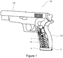
- FIG. 1 there is shown a firearm provided with an autonomous charger according to the invention.
- This firearm 100 advantageously has a butt 101 intended to be held by the hand of the user when firing with the firearm.
- An internal housing of said butt 101 is configured to at least partially receive the autonomous charger 10.
- the charger 10 has two main parts, namely a main housing 1 and a secondary housing 2 extending under this main housing 1.
- the main housing 1 In the operating position shown in the figure 1 , the main housing 1 is housed entirely inside the stock 101 and the secondary housing 2 forms an underlying extension of the stock 101.
- the secondary housing 2 has was designed so as not to exceed exceedingly the stock 101.
- the height of the secondary housing 2 as measured in a direction perpendicular to the flat bottom end face of the stock 101, will be advantageously lower at 2 cm and preferably less than 1 cm.
- the secondary housing 2 is advantageously provided with an opening 3, through which the number of cartridges contained in the charger 10 is displayed. This opening 3 will advantageously be arranged so that it is directed towards the user when he holds the stick 101 in his hand and that he directs the barrel 102 of the weapon 100 toward his shooting objective.
- the user can know at any time the actual content of the charger, without having to eject the magazine of the weapon and without having to stop shooting.
- the main elements of this charger comprise in particular a coil spring 4 housed entirely inside a central cavity 1a of the main housing 1, extending from its open upper end 1b to its open lower end 1c, said spring 4 resting on the one hand on the upper face 2a 1 of the secondary housing 2 and on the other hand on an elevator 5 for pushing the cartridges 6 contained in the upper part of the main housing 1 towards said upper end 1 b under the action of said spring 4.
- the elevator 5 is thus configured to slide inside said central cavity 1a in a longitudinal axial direction D, as shown in FIG.
- the secondary housing 2 is formed of an upper shell 2a and a lower lid 2b, fixed on the shell 2a by means of screws 2c for example.
- the shell 2a substantially defines a cylinder
- the bases 2a 1 and 2a 3 of substantially oval or oblong shape are connected by a side face 2a 2 .
- the oval or oblong shape of the bases 2a 1 and 2a 3 will advantageously correspond to the shape of the cross-section of the butt 101 so as to harmoniously integrate the magazine 10 with the firearm 100.
- the opening 3 through which the The user can read the value corresponding to the number of cartridges remaining in the magazine is, moreover, advantageously arranged along the side face 2a 2 , and preferably in alignment with the plane dividing the shell 2a in its greatest length .
- the opening 3 will be directly visible by the user when it holds the firearm in its normal operating position.
- the shell 2a is advantageously provided with a structural element 2a 4 disposed projecting at its upper face 2a 1 , said structural element 2a 4 defining a guide rail on which a complementary shape (not shown) ) provided at the lower end 1 c of the main housing 1.
- This indicator device 20 is in particular housed almost entirely within a cavity 2a 5 of the shell 2a opening on the lower face 2a 3 .
- the indicator device 20 is formed firstly of a flexible connection means 21, of wire or cable type, which is connected at its upper end 21a to a fixing support 5a housed inside the elevator 5
- the position of the fixing support 5a will advantageously be adjustable by means of a screw 5b, whose head 5b 1 will be accessible through a hole 5c formed in the upper face of the elevator 5, as shown in FIG. figure 2 .
- the user can, by more or less screwing or unscrewing the screw 5b inside the fixing support 5a, to modify in a fine manner the position of the fixing support 5a in a direction D 'which is slightly inclined with respect to the axial direction D of the main housing 1.
- this adjustment will in particular adjust the display so that the numbers indicating the number of cartridges in the charger are properly aligned with the opening 3.
- the flexible connecting means 21 is then fixed at its lower end on a rotary drum 22 housed inside the cavity 2a 5 , notammen t by means of a cylindrical pin 22a encased inside a hemicylindrical housing 22b of said rotary drum 22.
- the fixing may in particular be effected in the case of a flexible wire-type connection means as shown on the figure 5 , by knotting the wire 21 on itself at its lower end, said wire 21 having been introduced beforehand into a through hole formed through said cylindrical pin 22a.
- the rotary drum 22 is mounted inside the secondary housing 2 so as to be rotatable about a first hub 2d 1 disposed projecting from the bottom of the cavity 2a 5 , said hub 2d 1 defining an axis of rotation A1 substantially perpendicular to the plane P defined by the upper face 2a 1 and therefore also by the lower end 1c of the main housing 1.
- the rotary drum 22 serves in particular to support the winding of the wire 21 as and when the descent of the elevator 5 under the effect of the weight of the cartridges 6 introduced into the loader 10.
- the rotary drum 22 will advantageously include a first cylindrical periphery 22c 1 , in the form of a pulley, adapted to receive the wire 21 as it winds around the rotary drum 22.
- a first deflection means 23 adapted to pass said wire 21 from a first direction D1, in which it is substantially parallel to the direction D, to a second direction D2, in which it is substantially parallel to the plane P.
- This first deflection means 23 is necessary if one wants to avoid winding the wire 21 around a rotary drum 22 whose cylindrical periphery 22c 1 would be tangent to D1 direction, which would not adequately limit the height of the secondary housing 2.
- the deflection means 23 consists of a cylindrical bar 23 fixed at both ends 23a, 23b to the hull 2a, said bar 23 being disposed inside the cavity 2a 5 so as to be tangent to the direction D1 of the wire 21.
- the wire 21 is partially wound around said bar 21 before moving according to the direction D2.
- the cylindrical bar 23 In order to avoid deterioration or tearing of the wire 21, it will be preferable for the cylindrical bar 23 to have a completely smooth surface state.
- this first deflection means may also consist of a small diameter pulley.
- a second deflection means 24 is advantageously disposed between the first deflection means 23 and the rotary drum 22 so as to reduce the angle of tangency between the wire 21 and the cylindrical periphery 22c 1 .
- This tangent angle corresponds in fact to the angle measured between the direction D2 of the wire 21 and the radius of the circle substantially described by the wire 21 during winding, at the point of contact of the wire 21 with the cylindrical periphery 22c1.
- This second deflection means 24 decreases the risk of a mispositioning of the wire 21 around the cylindrical periphery 22c 1 at the time of winding. He avoids also that excessive bending forces are applied to the first deflection means 23.
- this second deflection means 24 consists of a cylindrical bar fixed at its upper end to the shell 2a, said bar being substantially parallel to axis A1.
- this energizing means consists of a spiral spring 25 which is connected at a first end 25a to a second hub 2d 2 arranged projecting from the bottom of the cavity 2a 5 and at a second end 25b to a second rotary drum 26 rotatably mounted on said second hub 2d 2 and rotatably driven with the first rotary drum 22, the axis of rotation A2 of the second rotary drum 26 being parallel to the axis of rotation A1 of the first rotary drum 22.
- the spiral spring 25 will in particular be configured to oppose the tensile force exerted indirectly by the spring 4 on the wire 21.
- the second rotary drum 26 has a larger diameter than the first drum rotating, 22, so that, during the mutual rotation of the two drums 22 and 26, the angular rotation speed of the second drum 26 is lower than the rotational speed.
- this reduction effect of the second rotary drum 26 makes it possible, in particular, to display a larger number of digits with the aid of a worn display means, or obviously, driven by said second rotary drum 26, which allows the use of the indicator device 20 for loaders of greater capacity.
- the spring spiral 25 is advantageously disposed inside an inner housing 26a of the second rotary drum 26, which avoids using an additional space inside the secondary housing 2 to accommodate said spiral spring 25.
- Such a configuration is only a preferred embodiment.
- Other configurations that may be envisaged may in particular provide for the use of another tensioning means, in particular a spring in compression, or for positioning the spiral spring, or the tensioning means in general, so that it acts directly on the first rotary drum 22.
- the indicator device 20 may also not be equipped with a second rotating drum. In this case, the display means mentioned above will be worn, or in any case driven only by the first rotary drum.
- this torque transmission means consists of a wire 27 connecting the first and second rotary drums 22 and 26.
- the wire 27 is fixed in particular on said rotary drums 22 and 26 so as to be able to wind during their mutual rotation around corresponding cylindrical rims of said drums 22 and 26, namely a second cylindrical periphery 22c 2 of the first rotary drum 22 and a first cylindrical periphery 26c 1 of the second rotary drum 26, each of said cylindrical peripheries 22c 2 and 26c 1 being generally in the form of a pulley.
- the first and second rotary drums 22 and 26 may also be connected by a cable, a tape, a belt or a gear.
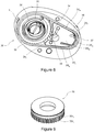
- This second rotary drum 26 comprises in particular a lateral face 26c which is defined by two adjacent cylindrical peripheries, namely an upper periphery 26c 1 , which has already been mentioned previously and which allows the winding of the wire 27 serving as torque transmission means, and a lower periphery 26c 2 , substantially delimiting a cylinder of revolution in which a central cavity 26a, serving as a housing for the spiral spring 25, is surrounded by an outer annular flange 26b having several functions.
- Said outer annular flange 26b comprises in particular a first L-shaped cavity 26b 1 , in which the end 25b of the spiral spring 25 is introduced before being fixed on the annular flange 26b.
- said first drum 22 rotates about the axis A1 in the direction of rotation indicated by the arrow F1 of the figure 5 .
- This rotation generates a concomitant rotation of the second rotary drum 26 about the axis A2 in the direction of rotation indicated by the arrow F2 of the figure 5 .
- This rotation produces a torsion of the spring 25, which tends to produce a reverse rotation of the second rotary drum 26 in the direction of rotation indicated by the arrow F3 of the figure 6b .
- the annular flange 26b has a second cavity 26b 2 defining a series of contiguous hemicylindrical housings for receiving a cylindrical pin 26d. Similar to the pin 22a, this cylindrical pin 26d has been configured to serve as an anchor point at one end of the wire 27.
- the user can modify the relative angular positions of the two rotary drums 22 and 26, which will allow a rough adjustment of the display of the value of the number of cartridges through the opening 3.
- the figure 3 also shows that the second cylindrical periphery 26c2 of the second rotary drum 26 has a series of consecutive digits evenly spaced along its circumference. These figures correspond to the number of cartridges contained in the magazine 10. These figures are positioned so as to be visible through the opening 3 formed through the shell 2a of the secondary housing 2, each digit being seen through said opening 3 in a very specific angular position of the second rotary drum 26, and thus also of the first rotary drum 22. These very specific angular positions of the first rotary drum 22 are obtained for corresponding specific positions of the elevator 5. along the axis D, which depend only on the number of cartridges contained in the charger 10. It may however happen that, following repeated use of the charger 10, variations in the restoring force of the spring 4 or the spring 25 occur.
- the figures carried by the second rotary drum 26 may no longer be properly aligned with the opening 3 in the different specific positions of the elevator 5 mentioned above.
- a similar situation could also occur if the secondary housing 2 provided with the indicator device 20 was to equip another type of charger.
- the user should therefore act on the fine and coarse adjustment means mentioned above to adjust both the angular position at the origin of the first rotary drum 22 and the relative position between the first and second drums
- the angular position at the origin of the first rotary drum 22 corresponds in fact to the position of the drum 22 when the magazine 10 contains no cartridge, as shown in FIG. figure 3 . The adjustment of this position is thus obtained by acting on the screw 5b.
- the secondary housing 2 of the present configuration differs in that it has a hub 2d 1 , the hub 2d 2 being replaced by a guide 2d 3 forming a portion raised relative to the bottom of the cavity 2a 5 .
- the guide 2d 3 has, over its entire height, a substantially trapezoidal shape, the convergent sides 2d 31 and 2d 32 of this guide 2d 3 being substantially straight so as to allow the translational guiding of a belt 36, as explained in detail in FIG. following, and the small base of the trapezium, forming a end 2d 33 of the guide 2d 3 , having a profile rounded so as to allow the rotational guidance of said belt 36.
- a leaf spring 37 is advantageously arranged so that it removes the belt 36 from said end 2d 33 .
- the leaf spring 37 has in particular been bent so that its ends are received within slots 2d 2d 34 and 35 formed in the guide 2d 3 at its end 2d 33.
- the belt 36 forms one of the constituent parts of the indicator device 30 intended to display the number of cartridges present in the magazine 10 through the opening 3 of the secondary housing 2.
- This indicator device 30 comprises, in particular, a flexible connection means 31, of type wire, for connecting the elevator 5 to a rotary drum 32, said winding drum, said winding drum 32 being mounted inside the secondary housing 2 so as to be rotatable about the hub 2d 1 along an axis rotation substantially perpendicular to the plane defined by the lower end of the main housing 1.
- the wire 31 Before being wound on the winding drum 32, the wire 31 is first deviated from its path by first and second deflection means 33 and 34 disposed inside the secondary housing 2, said first and second deflection means 33 and 34 being substantially similar to the deflection means 23 and 24 of the previous configuration, both from a structural and functional point of view. Once deflected, the wire 31 is then wound around a first cylindrical periphery 32c 1 of said winding drum 32, said first cylindrical periphery 32c 1 substantially defining a pulley.
- a spiral spring 35 housed inside a cavity of said winding drum 32 is configured to oppose the traction force exerted indirectly by the spring 4 on the wire 31, in the image of what the spiral spring 25 performs in the first configuration described.
- the winding drum 32 further comprises a second cylindrical periphery 32c 2 for driving the belt 36.
- said second cylindrical periphery 32c 2 is advantageously provided, on its entire length, a series of shaped protrusions tooth, regularly spaced apart, thus conferring on the circumference 32c 2 the shape of a toothed wheel.
- the belt 36 is successively wound partially around the second cylindrical periphery 32c 2 of said drum 32, guided in rectilinear translation on along one of the sides 2d 31 and 2d 32 of the guide 2d 3 , partially wound around the end 2d 33 and again guided in rectilinear translation along the other side 2d 31 or 2d 32 of said guide 2d 3 before go back to where it started.
- the belt 36 is positioned so that it passes in front of the opening 3 of the secondary housing 2. As illustrated by FIG. figure 7 , the belt 36 can thus serve as a means of displaying the number of cartridges contained in the charger 10.
- the figures may be replaced by a tonnage whose length visible through the opening 3 will indicate in an approximate manner the number of remaining cartridges.
- the numbers or the gauge may also include color codes to clearly indicate to the user that the charger is empty, or virtually empty, or, on the contrary, full, or substantially full.
- the charger 10 may also be useful to equip the charger 10 with a stand-alone lighting device so that the numbers or the gauge can be read in the dark.
- This lighting device can operate using any type of light source, in particular by means of a radioactive source, such as tritium, or a lamp equipped with batteries.
Landscapes
- Engineering & Computer Science (AREA)
- General Engineering & Computer Science (AREA)
- Charge And Discharge Circuits For Batteries Or The Like (AREA)
- Packaging Of Annular Or Rod-Shaped Articles, Wearing Apparel, Cassettes, Or The Like (AREA)
Claims (18)
- Unabhängiges Magazin (10), das für eine Schusswaffe (100) bestimmt ist, umfassend:- ein Hauptgehäuse (1), das dazu bestimmt ist, mehrere Patronen (6) aufzunehmen, wobei das Hauptgehäuse (1) ein offenes oberes Ende (1 b) aufweist, durch das die Patronen (6) geladen und entladen werden,- einen Schieber (5), der in dem Hauptgehäuse (1) angeordnet ist, wobei der Schieber (5) entlang einer axialen Längsrichtung (D) des Hauptgehäuses (1) verschiebbar ist,- eine Feder (4), die den Schieber (5) in Richtung des oberen Endes (1b) beaufschlagt, um die Patronen (6) in Richtung des oberen Endes (1 b) zu drücken,- ein Sekundärgehäuse (2), das vorzugsweise abnehmbar an einem im Wesentlichen ebenen unteren Ende (1c) des Hauptgehäuses (1) befestigt ist,- eine Anzeigevorrichtung (20, 30), die mindestens teilweise im Inneren des Sekundärgehäuses (2) angeordnet ist und dazu bestimmt ist, die Anzahl an Patronen (6), die in dem Hauptgehäuse (1) enthalten sind, anzugeben,
wobei die Anzeigevorrichtung (20, 30) Folgendes aufweist:- eine drehbare Trommel (22, 32), die sogenannte Aufwickeltrommel, die im Inneren des Sekundärgehäuses (2) angeordnet ist und deren Drehachse (A1) im Wesentlichen senkrecht zu der Ebene (P) angeordnet ist, die durch das untere Ende (1c) des Hauptgehäuses (1) definiert ist,- ein flexibles Verbindungsmittel (21, 31), das dazu bestimmt ist, den Schieber (5) mit der Aufwickeltrommel (22, 32) zu verbinden, wobei die Aufwickeltrommel (22, 32) konfiguriert ist, um das Aufwickeln beziehungsweise das Abwickeln des flexiblen Verbindungsmittels (21, 31) um mindestens einen Teil ihres peripheren Umfangs (22c1, 32c1) zu ermöglichen, wenn sich der Schieber (5) dem unteren Ende (1c) nähert, beziehungsweise sich davon entfernt,- ein Mittel zum Spannen (25, 35), das dazu bestimmt ist, das flexible Verbindungsmittel (21, 31), insbesondere bei seinem Aufwickeln um die Aufwickeltrommel (22, 32) zu spannen,- mindestens ein Ablenkmittel (23, 33), das dazu bestimmt ist, die Richtung (D1, D2), die durch das flexible Verbindungsmittel definiert ist, derart zu ändern, dass die Richtung (D1) im Wesentlichen parallel zu der axialen Richtung (D) des Hauptgehäuses (1) in einem Abschnitt ist, der sich zwischen dem Schieber (5) und dem Ablenkmittel (23, 33) erstreckt, und dass die Richtung (D2) im Wesentlichen parallel zu der Ebene (P), die durch das untere Ende (1c) des Hauptgehäuses (1) definiert ist, in einem Abschnitt, der sich zwischen dem Ablenkmittel (23, 33) und der Aufwickeltrommel (22, 32) erstreckt, ist,- ein Anzeigemittel (26, 36), das dazu bestimmt ist, die Anzahl an Patronen (6), die in dem Hauptgehäuse (1) enthalten sind, in Abhängigkeit von der Winkelposition der Aufwickeltrommel (22) anzuzeigen. - Magazin (10) nach Anspruch 1, dadurch gekennzeichnet, dass das flexible Verbindungsmittel (21, 31) drahtförmig ist und vorzugsweise aus einem Draht oder einem Kabel gebildet ist.
- Magazin (10) nach einem der vorhergehenden Ansprüche, dadurch gekennzeichnet, dass das Mittel zum Spannen (25, 35) eine Feder, vorzugsweise eine Spiralfeder, aufweist, die an einem ersten Ende mit dem Sekundärgehäuse (2) und an einem zweiten Ende mit der Aufwickeltrommel (22, 32) verbunden ist.
- Magazin (10) nach dem vorhergehenden Anspruch, dadurch gekennzeichnet, dass die Feder eine Spiralfeder (35) ist, die vollständig im Inneren eines Innengehäuses der Aufwickeltrommel (32) angeordnet ist.
- Magazin (10) nach einem der Ansprüche 1 und 2, dadurch gekennzeichnet, dass das Mittel zum Spannen (25) eine Feder, vorzugsweise eine Spiralfeder, aufweist, die an einem ersten Ende mit dem Sekundärgehäuse (2) und an einem zweiten Ende mit einer zusätzlichen drehbaren Trommel (26), der sogenannten Übertragungstrommel, verbunden ist, die mit der Aufwickeltrommel (22) gegenseitig in Drehung versetzt wird, wobei die Drehachse (A2) der Übertragungstrommel (26) parallel zu der Drehachse (A1) der Aufwickeltrommel (22) ist.
- Magazin (10) nach dem vorhergehenden Anspruch, dadurch gekennzeichnet, dass die Feder eine Spiralfeder (25) ist, die vollständig im Inneren eines Innengehäuses (26a) der Übertragungstrommel (26) angeordnet ist.
- Magazin (10) nach einem der Ansprüche 5 und 6, dadurch gekennzeichnet, dass die Aufwickeltrommel (22) und die Übertragungstrommel (26) durch ein Drehmomentübertragungsmittel (27) gegenseitig in Drehung versetzt werden.
- Magazin (10) nach dem vorhergehenden Anspruch, dadurch gekennzeichnet, dass das Drehmomentübertragungsmittel (27) aus einem Riemen, einem Kabel, einem Draht oder einem Getriebe ausgewählt ist.
- Magazin (10) nach einem der Ansprüche 5 bis 8, dadurch gekennzeichnet, dass die Mittelebene der Aufwickeltrommel (22) im Wesentlichen mit der Mittelebene der Übertragungstrommel (26) ausgerichtet ist, um den Raum zu optimieren, der im Inneren des Sekundärgehäuses (2) verfügbar ist.
- Magazin (10) nach einem der Ansprüche 3 und 4, dadurch gekennzeichnet, dass das Anzeigemittel aus einer Markierung gebildet ist, die auf der Aufwickeltrommel angebracht ist und durch eine Öffnung (3) sichtbar ist, die in dem Sekundärgehäuse (2) ausgebildet ist.
- Magazin (10) nach einem der Ansprüche 3 und 4, dadurch gekennzeichnet, dass das Anzeigemittel aus einer Markierung gebildet ist, die auf einem Riemen (36) angebracht ist, der von der Aufwickeltrommel (32) angetrieben wird, und durch eine Öffnung (3) sichtbar ist, die in dem Sekundärgehäuse (2) ausgebildet ist.
- Magazin (10) nach einem der Ansprüche 5 bis 9, dadurch gekennzeichnet, dass das Anzeigemittel aus einer Markierung gebildet ist, die auf der Übertragungstrommel (26) angebracht ist und durch eine Öffnung (3) sichtbar ist, die in dem Sekundärgehäuse (2) ausgebildet ist.
- Magazin (10) nach Anspruch 8, dadurch gekennzeichnet, dass das Anzeigemittel aus einer Markierung gebildet ist, die auf einem Riemen angebracht ist, der gegenseitig die Aufwickeltrommel (22) und die Übertragungstrommel (26) antreibt, und durch eine Öffnung (3) sichtbar ist, die in dem Sekundärgehäuse (2) ausgebildet ist.
- Magazin (10) nach einem der Ansprüche 10 bis 13, dadurch gekennzeichnet, dass die Markierung aus einer Reihe von aufeinanderfolgenden Zahlen besteht, die auf einem äußeren Umfang der Aufwickeltrommel (22, 32), der Übertragungstrommel (26) oder des Riemens (36) gleichmäßig beabstandet sind, wobei die Zahlen der Anzahl an Patronen (6) entsprechen, die in dem Hauptgehäuse (1) enthalten sind.
- Magazin (10) nach einem der Ansprüche 10 bis 13, dadurch gekennzeichnet, dass die Markierung aus einem Messstab besteht, der auf einem äußeren Umfang der Aufwickeltrommel (22, 32), der Übertragungstrommel (26) oder des Riemens (36) vorhanden ist, wobei die Länge des Messstabs, die durch die Öffnung (3) sichtbar ist, proportional zu der Anzahl an Patronen (6) ist, die in dem Hauptgehäuse (1) enthalten sind.
- Magazin (10) nach einem der vorhergehenden Ansprüche, dadurch gekennzeichnet dass die Höhe des Sekundärgehäuses (2), die in einer Richtung parallel zu der Drehachse (A1) der Aufwickeltrommel (22, 32) gemessen ist, niedriger als 2 cm und vorzugsweise niedriger als 1 cm ist.
- Kombination von einer Schusswaffe (100), die dazu bestimmt ist, Patronen (6) von dieser abzufeuern, wobei die Schusswaffe (100) ein Magazingehäuse aufweist, und von einem unabhängigen Magazin (10) nach einem der Ansprüche 1 bis 16, das ausgebildet ist, um in dem Magazingehäuse aufgenommen zu werden, um der Schusswaffe (100) Patronen (6) bereitzustellen.
- Kombination nach Anspruch 17, dadurch gekennzeichnet, dass eine Öffnung (3) in dem Sekundärgehäuse (2) des Magazins (10) ausgebildet ist, um das Anzeigen der Anzahl an Patronen (6), die in dem Magazin (10) enthalten sind, zu ermöglichen, wobei die Öffnung (3) derart angeordnet ist, dass sie zu dem Benutzer ausgerichtet ist, wenn er die Schusswaffe (100) in ihrer normalen Betriebsfunktion hält.
Priority Applications (1)
| Application Number | Priority Date | Filing Date | Title |
|---|---|---|---|
| EP14741959.2A EP3025115B9 (de) | 2013-07-26 | 2014-07-10 | Magazin für schusswaffe, das mit einer anzeigevorrichtung für die anzahl der verbleibenden patronen ausgestattet ist |
Applications Claiming Priority (3)
| Application Number | Priority Date | Filing Date | Title |
|---|---|---|---|
| EP13178242.7A EP2829837A1 (de) | 2013-07-26 | 2013-07-26 | Magazin für Schusswaffe, das mit einer Anzeigevorrichtung für die Anzahl der verbleibenden Patronen ausgestattet ist |
| PCT/IB2014/062999 WO2015011596A1 (fr) | 2013-07-26 | 2014-07-10 | Chargeur pour arme a feu muni d'un dispositif indicateur du nombre de cartouches restantes |
| EP14741959.2A EP3025115B9 (de) | 2013-07-26 | 2014-07-10 | Magazin für schusswaffe, das mit einer anzeigevorrichtung für die anzahl der verbleibenden patronen ausgestattet ist |
Publications (3)
| Publication Number | Publication Date |
|---|---|
| EP3025115A1 EP3025115A1 (de) | 2016-06-01 |
| EP3025115B1 true EP3025115B1 (de) | 2017-05-31 |
| EP3025115B9 EP3025115B9 (de) | 2017-08-30 |
Family
ID=48874905
Family Applications (2)
| Application Number | Title | Priority Date | Filing Date |
|---|---|---|---|
| EP13178242.7A Withdrawn EP2829837A1 (de) | 2013-07-26 | 2013-07-26 | Magazin für Schusswaffe, das mit einer Anzeigevorrichtung für die Anzahl der verbleibenden Patronen ausgestattet ist |
| EP14741959.2A Active EP3025115B9 (de) | 2013-07-26 | 2014-07-10 | Magazin für schusswaffe, das mit einer anzeigevorrichtung für die anzahl der verbleibenden patronen ausgestattet ist |
Family Applications Before (1)
| Application Number | Title | Priority Date | Filing Date |
|---|---|---|---|
| EP13178242.7A Withdrawn EP2829837A1 (de) | 2013-07-26 | 2013-07-26 | Magazin für Schusswaffe, das mit einer Anzeigevorrichtung für die Anzahl der verbleibenden Patronen ausgestattet ist |
Country Status (3)
| Country | Link |
|---|---|
| US (1) | US9797667B2 (de) |
| EP (2) | EP2829837A1 (de) |
| WO (1) | WO2015011596A1 (de) |
Families Citing this family (18)
| Publication number | Priority date | Publication date | Assignee | Title |
|---|---|---|---|---|
| US9395129B2 (en) * | 2012-01-25 | 2016-07-19 | Advanced Combat Solutions Inc. | Light emitting firearm magazine indicator |
| US10234228B2 (en) * | 2015-07-01 | 2019-03-19 | Matt Person | Firearm noise suppressor |
| US11022289B2 (en) * | 2015-12-04 | 2021-06-01 | Christopher Morris | Selectively illuminating firearm |
| US20190222771A1 (en) | 2016-10-14 | 2019-07-18 | Laser Aiming Systems Corporation | Gun-mounted recording device |
| US10962314B2 (en) | 2017-04-12 | 2021-03-30 | Laser Aiming Systems Corporation | Firearm including electronic components to enhance user experience |
| US10234220B2 (en) * | 2017-04-14 | 2019-03-19 | Kent J. Myers | Detachable box magazine with follower retraction member |
| US10480877B1 (en) * | 2017-04-14 | 2019-11-19 | Kent J. Myers | Detachable box magazine with follower retraction member |
| WO2019173791A1 (en) | 2018-03-08 | 2019-09-12 | Maztech Industries, LLC | Firearm ammunition availability detection system |
| CN108469201A (zh) * | 2018-05-11 | 2018-08-31 | 普达迪泰(天津)智能装备科技有限公司 | 一种基于无线网络的可控停止供弹系统 |
| US10845142B2 (en) * | 2018-07-02 | 2020-11-24 | Victor Flood | Methods, systems, apparatuses and devices for facilitating counting and displaying of an ammunition count of a magazine of a firearm |
| US11719497B2 (en) | 2018-10-22 | 2023-08-08 | Magpul Industries Corp. | Determination of round count by hall switch encoding |
| US11971238B2 (en) | 2018-10-22 | 2024-04-30 | Magpul Industries Corp. | Determination of round count by hall switch encoding |
| WO2020086598A1 (en) | 2018-10-22 | 2020-04-30 | Magpul Industries Corp. | Determination of round count by hall switch encoding |
| CN109373805B (zh) * | 2018-12-07 | 2023-08-22 | 宁波诺驰贸易有限公司 | 弹匣快速装弹装置 |
| US12173992B1 (en) | 2020-07-21 | 2024-12-24 | Laser Aiming Systems Corporation | Gun mounted recording device with quick release battery |
| US12130121B1 (en) | 2020-07-21 | 2024-10-29 | Laser Aiming Systems Corporation | Data redundancy and hardware tracking system for gun-mounted recording device |
| WO2023086840A1 (en) | 2021-11-12 | 2023-05-19 | Maztech Industries, LLC | Firearm ammunition availability detection system |
| GB202313821D0 (en) * | 2023-09-11 | 2023-10-25 | Hamersham Ltd | Firearm magazine and system for monitoring rounds |
Family Cites Families (13)
| Publication number | Priority date | Publication date | Assignee | Title |
|---|---|---|---|---|
| FR18306E (fr) | 1914-03-23 | Pierre Dechorin | Indicateur de chargement pour pistolets automatiques | |
| US1126726A (en) * | 1913-10-06 | 1915-02-02 | Frederick A Diestelkamp | Automatic magazine-firearm. |
| US1252094A (en) * | 1916-10-07 | 1918-01-01 | Adolphe Henri Rochette De Lempdes | Cartridge-indicator for repeating or automatic small-arms. |
| US1451339A (en) * | 1918-08-16 | 1923-04-10 | Kottas Arthur | Magazine firearm |
| US2114311A (en) * | 1936-11-21 | 1938-04-19 | Nomar Louis Nolan | Combined magazine and extension stock for automatic pistols |
| DE3233749A1 (de) * | 1982-09-11 | 1984-03-15 | Rheinmetall GmbH, 4000 Düsseldorf | Zuendhuelsenmagazin fuer einen geschuetzkeilverschluss |
| US5206444A (en) | 1990-11-16 | 1993-04-27 | Oliver Harry M | Device that displays count of rounds in firearm magazines |
| US5799432A (en) * | 1997-02-12 | 1998-09-01 | Barry M. Wright, Sr. | Self-contained magazine and weapon system incorporating same |
| WO2008132739A2 (en) * | 2007-04-30 | 2008-11-06 | Ori Gur-Ari | Magazine status indicator |
| EP2167899A2 (de) * | 2007-06-13 | 2010-03-31 | Ray Kim | System und verfahren zur überwachung der munitionsversorgung in einem magazin |
| KR100981614B1 (ko) | 2008-04-30 | 2010-09-10 | 에이치앤피테크놀로지(주) | 실탄 계수기가 부설된 탄창 |
| IL206546A (en) * | 2010-06-22 | 2014-05-28 | Guy Gabay | Additive to cartridge |
| US8991084B2 (en) * | 2013-03-11 | 2015-03-31 | Mark S. Williams | Apparatus and methods for tracking ammunition supply in a magazine |
-
2013
- 2013-07-26 EP EP13178242.7A patent/EP2829837A1/de not_active Withdrawn
-
2014
- 2014-07-10 WO PCT/IB2014/062999 patent/WO2015011596A1/fr not_active Ceased
- 2014-07-10 US US14/907,755 patent/US9797667B2/en active Active
- 2014-07-10 EP EP14741959.2A patent/EP3025115B9/de active Active
Non-Patent Citations (1)
| Title |
|---|
| None * |
Also Published As
| Publication number | Publication date |
|---|---|
| WO2015011596A1 (fr) | 2015-01-29 |
| EP3025115A1 (de) | 2016-06-01 |
| EP2829837A1 (de) | 2015-01-28 |
| US20160169602A1 (en) | 2016-06-16 |
| US9797667B2 (en) | 2017-10-24 |
| EP3025115B9 (de) | 2017-08-30 |
Similar Documents
| Publication | Publication Date | Title |
|---|---|---|
| EP3025115B1 (de) | Magazin für schusswaffe, das mit einer anzeigevorrichtung für die anzahl der verbleibenden patronen ausgestattet ist | |
| EP2965647B1 (de) | Aufroll- und sperrklinkenblockiervorrichtung eines schnürbands | |
| EP2166419B1 (de) | Uhrwerk, das eine Konstantkraftvorrichtung aufweist | |
| EP2450235A1 (de) | Gurtspannvorrichtung | |
| WO2013171405A1 (fr) | Applicateur de franges de faux-cils | |
| CH706214B1 (fr) | Barillet de pièce d'horlogerie. | |
| EP2864841A2 (de) | Ansteuerungsvorrichtung für uhrwerk | |
| EP3234493A1 (de) | Manuelle werfer mit entfernt gelegener steuerung | |
| EP3100633A1 (de) | Elektrisches haarpflegegerät | |
| EP2735919B1 (de) | Uhrwerk, das eine Schnecke umfasst | |
| EP3890576B1 (de) | Deckel für küchengerät mit manuell betriebener seilvorrichtung | |
| CH706701B1 (fr) | Mécanisme de remontage automatique. | |
| EP3306415B1 (de) | Mechanisches uhrwerk mit erfassung der gangreserve | |
| CH707271A2 (fr) | Mouvement de montre comportant une fusée. | |
| WO2011134960A1 (fr) | Pièce d'horlogerie | |
| WO2008025810A1 (fr) | Dispositif pour annuler la torsion d'un lien entre une extremite fixe et une extremite tournante | |
| EP4161333A1 (de) | Küchengerät mit schnurantriebsvorrichtung mit abnehmbarer steuerung | |
| FR2955570A1 (fr) | Dispositif de securite pour enrouleurs a rembobinage automatique pour cables, tubes et similaires, et enrouleur a rembobinage automatique pour cables, tubes et similaires dote d'un tel dispositif. | |
| FR3101253A1 (fr) | Dispositif antichute, de préférence à rappel automatique | |
| EP0099154A1 (de) | Photographischer Schlitzverschluss | |
| CH704650A1 (fr) | Mouvement de montre mécanique comprenant un accumulateur d'énergie déformable en flexion et/ou en torsion. | |
| CH707985B1 (fr) | Mouvement de montre à remontage manuel par bouton-poussoir. | |
| CH382557A (fr) | Appareil cinématographique | |
| CH704249B1 (fr) | Organe moteur pour mouvement horloger. | |
| EP2868852A1 (de) | Universalvorrichtung für das automatische Schließen von Schiebeöffnungselementen, insbesondere Schranktüren |
Legal Events
| Date | Code | Title | Description |
|---|---|---|---|
| PUAI | Public reference made under article 153(3) epc to a published international application that has entered the european phase |
Free format text: ORIGINAL CODE: 0009012 |
|
| 17P | Request for examination filed |
Effective date: 20160226 |
|
| AK | Designated contracting states |
Kind code of ref document: A1 Designated state(s): AL AT BE BG CH CY CZ DE DK EE ES FI FR GB GR HR HU IE IS IT LI LT LU LV MC MK MT NL NO PL PT RO RS SE SI SK SM TR |
|
| AX | Request for extension of the european patent |
Extension state: BA ME |
|
| DAX | Request for extension of the european patent (deleted) | ||
| GRAP | Despatch of communication of intention to grant a patent |
Free format text: ORIGINAL CODE: EPIDOSNIGR1 |
|
| STAA | Information on the status of an ep patent application or granted ep patent |
Free format text: STATUS: GRANT OF PATENT IS INTENDED |
|
| INTG | Intention to grant announced |
Effective date: 20161125 |
|
| GRAS | Grant fee paid |
Free format text: ORIGINAL CODE: EPIDOSNIGR3 |
|
| GRAJ | Information related to disapproval of communication of intention to grant by the applicant or resumption of examination proceedings by the epo deleted |
Free format text: ORIGINAL CODE: EPIDOSDIGR1 |
|
| GRAL | Information related to payment of fee for publishing/printing deleted |
Free format text: ORIGINAL CODE: EPIDOSDIGR3 |
|
| STAA | Information on the status of an ep patent application or granted ep patent |
Free format text: STATUS: REQUEST FOR EXAMINATION WAS MADE |
|
| GRAR | Information related to intention to grant a patent recorded |
Free format text: ORIGINAL CODE: EPIDOSNIGR71 |
|
| STAA | Information on the status of an ep patent application or granted ep patent |
Free format text: STATUS: GRANT OF PATENT IS INTENDED |
|
| GRAA | (expected) grant |
Free format text: ORIGINAL CODE: 0009210 |
|
| STAA | Information on the status of an ep patent application or granted ep patent |
Free format text: STATUS: THE PATENT HAS BEEN GRANTED |
|
| INTC | Intention to grant announced (deleted) | ||
| AK | Designated contracting states |
Kind code of ref document: B1 Designated state(s): AL AT BE BG CH CY CZ DE DK EE ES FI FR GB GR HR HU IE IS IT LI LT LU LV MC MK MT NL NO PL PT RO RS SE SI SK SM TR |
|
| INTG | Intention to grant announced |
Effective date: 20170424 |
|
| REG | Reference to a national code |
Ref country code: CH Ref legal event code: EP Ref country code: GB Ref legal event code: FG4D Free format text: NOT ENGLISH |
|
| REG | Reference to a national code |
Ref country code: AT Ref legal event code: REF Ref document number: 897879 Country of ref document: AT Kind code of ref document: T Effective date: 20170615 |
|
| REG | Reference to a national code |
Ref country code: IE Ref legal event code: FG4D Free format text: LANGUAGE OF EP DOCUMENT: FRENCH |
|
| REG | Reference to a national code |
Ref country code: DE Ref legal event code: R096 Ref document number: 602014010338 Country of ref document: DE |
|
| REG | Reference to a national code |
Ref country code: FR Ref legal event code: PLFP Year of fee payment: 4 |
|
| REG | Reference to a national code |
Ref country code: CH Ref legal event code: NV Representative=s name: ABREMA AGENCE BREVET ET MARQUES, GANGUILLET, CH |
|
| REG | Reference to a national code |
Ref country code: NL Ref legal event code: MP Effective date: 20170531 |
|
| REG | Reference to a national code |
Ref country code: LT Ref legal event code: MG4D |
|
| REG | Reference to a national code |
Ref country code: AT Ref legal event code: MK05 Ref document number: 897879 Country of ref document: AT Kind code of ref document: T Effective date: 20170531 |
|
| PG25 | Lapsed in a contracting state [announced via postgrant information from national office to epo] |
Ref country code: FI Free format text: LAPSE BECAUSE OF FAILURE TO SUBMIT A TRANSLATION OF THE DESCRIPTION OR TO PAY THE FEE WITHIN THE PRESCRIBED TIME-LIMIT Effective date: 20170531 Ref country code: NO Free format text: LAPSE BECAUSE OF FAILURE TO SUBMIT A TRANSLATION OF THE DESCRIPTION OR TO PAY THE FEE WITHIN THE PRESCRIBED TIME-LIMIT Effective date: 20170831 Ref country code: AT Free format text: LAPSE BECAUSE OF FAILURE TO SUBMIT A TRANSLATION OF THE DESCRIPTION OR TO PAY THE FEE WITHIN THE PRESCRIBED TIME-LIMIT Effective date: 20170531 Ref country code: HR Free format text: LAPSE BECAUSE OF FAILURE TO SUBMIT A TRANSLATION OF THE DESCRIPTION OR TO PAY THE FEE WITHIN THE PRESCRIBED TIME-LIMIT Effective date: 20170531 Ref country code: GR Free format text: LAPSE BECAUSE OF FAILURE TO SUBMIT A TRANSLATION OF THE DESCRIPTION OR TO PAY THE FEE WITHIN THE PRESCRIBED TIME-LIMIT Effective date: 20170901 Ref country code: LT Free format text: LAPSE BECAUSE OF FAILURE TO SUBMIT A TRANSLATION OF THE DESCRIPTION OR TO PAY THE FEE WITHIN THE PRESCRIBED TIME-LIMIT Effective date: 20170531 Ref country code: ES Free format text: LAPSE BECAUSE OF FAILURE TO SUBMIT A TRANSLATION OF THE DESCRIPTION OR TO PAY THE FEE WITHIN THE PRESCRIBED TIME-LIMIT Effective date: 20170531 |
|
| PG25 | Lapsed in a contracting state [announced via postgrant information from national office to epo] |
Ref country code: RS Free format text: LAPSE BECAUSE OF FAILURE TO SUBMIT A TRANSLATION OF THE DESCRIPTION OR TO PAY THE FEE WITHIN THE PRESCRIBED TIME-LIMIT Effective date: 20170531 Ref country code: LV Free format text: LAPSE BECAUSE OF FAILURE TO SUBMIT A TRANSLATION OF THE DESCRIPTION OR TO PAY THE FEE WITHIN THE PRESCRIBED TIME-LIMIT Effective date: 20170531 Ref country code: BG Free format text: LAPSE BECAUSE OF FAILURE TO SUBMIT A TRANSLATION OF THE DESCRIPTION OR TO PAY THE FEE WITHIN THE PRESCRIBED TIME-LIMIT Effective date: 20170831 Ref country code: NL Free format text: LAPSE BECAUSE OF FAILURE TO SUBMIT A TRANSLATION OF THE DESCRIPTION OR TO PAY THE FEE WITHIN THE PRESCRIBED TIME-LIMIT Effective date: 20170531 Ref country code: IS Free format text: LAPSE BECAUSE OF FAILURE TO SUBMIT A TRANSLATION OF THE DESCRIPTION OR TO PAY THE FEE WITHIN THE PRESCRIBED TIME-LIMIT Effective date: 20170930 Ref country code: SE Free format text: LAPSE BECAUSE OF FAILURE TO SUBMIT A TRANSLATION OF THE DESCRIPTION OR TO PAY THE FEE WITHIN THE PRESCRIBED TIME-LIMIT Effective date: 20170531 |
|
| PG25 | Lapsed in a contracting state [announced via postgrant information from national office to epo] |
Ref country code: RO Free format text: LAPSE BECAUSE OF FAILURE TO SUBMIT A TRANSLATION OF THE DESCRIPTION OR TO PAY THE FEE WITHIN THE PRESCRIBED TIME-LIMIT Effective date: 20170531 Ref country code: EE Free format text: LAPSE BECAUSE OF FAILURE TO SUBMIT A TRANSLATION OF THE DESCRIPTION OR TO PAY THE FEE WITHIN THE PRESCRIBED TIME-LIMIT Effective date: 20170531 Ref country code: SK Free format text: LAPSE BECAUSE OF FAILURE TO SUBMIT A TRANSLATION OF THE DESCRIPTION OR TO PAY THE FEE WITHIN THE PRESCRIBED TIME-LIMIT Effective date: 20170531 Ref country code: CZ Free format text: LAPSE BECAUSE OF FAILURE TO SUBMIT A TRANSLATION OF THE DESCRIPTION OR TO PAY THE FEE WITHIN THE PRESCRIBED TIME-LIMIT Effective date: 20170531 Ref country code: DK Free format text: LAPSE BECAUSE OF FAILURE TO SUBMIT A TRANSLATION OF THE DESCRIPTION OR TO PAY THE FEE WITHIN THE PRESCRIBED TIME-LIMIT Effective date: 20170531 |
|
| PG25 | Lapsed in a contracting state [announced via postgrant information from national office to epo] |
Ref country code: PL Free format text: LAPSE BECAUSE OF FAILURE TO SUBMIT A TRANSLATION OF THE DESCRIPTION OR TO PAY THE FEE WITHIN THE PRESCRIBED TIME-LIMIT Effective date: 20170531 Ref country code: SM Free format text: LAPSE BECAUSE OF FAILURE TO SUBMIT A TRANSLATION OF THE DESCRIPTION OR TO PAY THE FEE WITHIN THE PRESCRIBED TIME-LIMIT Effective date: 20170531 Ref country code: IT Free format text: LAPSE BECAUSE OF FAILURE TO SUBMIT A TRANSLATION OF THE DESCRIPTION OR TO PAY THE FEE WITHIN THE PRESCRIBED TIME-LIMIT Effective date: 20170531 |
|
| REG | Reference to a national code |
Ref country code: DE Ref legal event code: R097 Ref document number: 602014010338 Country of ref document: DE |
|
| PLBE | No opposition filed within time limit |
Free format text: ORIGINAL CODE: 0009261 |
|
| STAA | Information on the status of an ep patent application or granted ep patent |
Free format text: STATUS: NO OPPOSITION FILED WITHIN TIME LIMIT |
|
| REG | Reference to a national code |
Ref country code: IE Ref legal event code: MM4A |
|
| PG25 | Lapsed in a contracting state [announced via postgrant information from national office to epo] |
Ref country code: IE Free format text: LAPSE BECAUSE OF NON-PAYMENT OF DUE FEES Effective date: 20170710 |
|
| REG | Reference to a national code |
Ref country code: BE Ref legal event code: MM Effective date: 20170731 |
|
| 26N | No opposition filed |
Effective date: 20180301 |
|
| PG25 | Lapsed in a contracting state [announced via postgrant information from national office to epo] |
Ref country code: SI Free format text: LAPSE BECAUSE OF FAILURE TO SUBMIT A TRANSLATION OF THE DESCRIPTION OR TO PAY THE FEE WITHIN THE PRESCRIBED TIME-LIMIT Effective date: 20170531 |
|
| PG25 | Lapsed in a contracting state [announced via postgrant information from national office to epo] |
Ref country code: LU Free format text: LAPSE BECAUSE OF NON-PAYMENT OF DUE FEES Effective date: 20170710 |
|
| REG | Reference to a national code |
Ref country code: FR Ref legal event code: PLFP Year of fee payment: 5 |
|
| PG25 | Lapsed in a contracting state [announced via postgrant information from national office to epo] |
Ref country code: BE Free format text: LAPSE BECAUSE OF NON-PAYMENT OF DUE FEES Effective date: 20170731 |
|
| PG25 | Lapsed in a contracting state [announced via postgrant information from national office to epo] |
Ref country code: MT Free format text: LAPSE BECAUSE OF FAILURE TO SUBMIT A TRANSLATION OF THE DESCRIPTION OR TO PAY THE FEE WITHIN THE PRESCRIBED TIME-LIMIT Effective date: 20170531 |
|
| PG25 | Lapsed in a contracting state [announced via postgrant information from national office to epo] |
Ref country code: HU Free format text: LAPSE BECAUSE OF FAILURE TO SUBMIT A TRANSLATION OF THE DESCRIPTION OR TO PAY THE FEE WITHIN THE PRESCRIBED TIME-LIMIT; INVALID AB INITIO Effective date: 20140710 Ref country code: MC Free format text: LAPSE BECAUSE OF FAILURE TO SUBMIT A TRANSLATION OF THE DESCRIPTION OR TO PAY THE FEE WITHIN THE PRESCRIBED TIME-LIMIT Effective date: 20170531 |
|
| PG25 | Lapsed in a contracting state [announced via postgrant information from national office to epo] |
Ref country code: CY Free format text: LAPSE BECAUSE OF FAILURE TO SUBMIT A TRANSLATION OF THE DESCRIPTION OR TO PAY THE FEE WITHIN THE PRESCRIBED TIME-LIMIT Effective date: 20170531 |
|
| PG25 | Lapsed in a contracting state [announced via postgrant information from national office to epo] |
Ref country code: MK Free format text: LAPSE BECAUSE OF FAILURE TO SUBMIT A TRANSLATION OF THE DESCRIPTION OR TO PAY THE FEE WITHIN THE PRESCRIBED TIME-LIMIT Effective date: 20170531 |
|
| PG25 | Lapsed in a contracting state [announced via postgrant information from national office to epo] |
Ref country code: TR Free format text: LAPSE BECAUSE OF FAILURE TO SUBMIT A TRANSLATION OF THE DESCRIPTION OR TO PAY THE FEE WITHIN THE PRESCRIBED TIME-LIMIT Effective date: 20170531 |
|
| PG25 | Lapsed in a contracting state [announced via postgrant information from national office to epo] |
Ref country code: PT Free format text: LAPSE BECAUSE OF FAILURE TO SUBMIT A TRANSLATION OF THE DESCRIPTION OR TO PAY THE FEE WITHIN THE PRESCRIBED TIME-LIMIT Effective date: 20170531 |
|
| PG25 | Lapsed in a contracting state [announced via postgrant information from national office to epo] |
Ref country code: AL Free format text: LAPSE BECAUSE OF FAILURE TO SUBMIT A TRANSLATION OF THE DESCRIPTION OR TO PAY THE FEE WITHIN THE PRESCRIBED TIME-LIMIT Effective date: 20170531 |
|
| REG | Reference to a national code |
Ref country code: CH Ref legal event code: PFUS Owner name: TECHTONIQUE SA, CH Free format text: FORMER OWNER: TECHTONIQUE SA, CH |
|
| REG | Reference to a national code |
Ref country code: DE Ref legal event code: R082 Ref document number: 602014010338 Country of ref document: DE Representative=s name: KARAKATSANIS, GEORGIOS, DR., DE |
|
| PGFP | Annual fee paid to national office [announced via postgrant information from national office to epo] |
Ref country code: DE Payment date: 20240719 Year of fee payment: 11 |
|
| PGFP | Annual fee paid to national office [announced via postgrant information from national office to epo] |
Ref country code: GB Payment date: 20240723 Year of fee payment: 11 |
|
| PGFP | Annual fee paid to national office [announced via postgrant information from national office to epo] |
Ref country code: FR Payment date: 20250718 Year of fee payment: 12 |
|
| PGFP | Annual fee paid to national office [announced via postgrant information from national office to epo] |
Ref country code: CH Payment date: 20250801 Year of fee payment: 12 |