EP3025100B1 - Système de chauffage et procédé de fonctionnement de ce système - Google Patents
Système de chauffage et procédé de fonctionnement de ce système Download PDFInfo
- Publication number
- EP3025100B1 EP3025100B1 EP14750692.7A EP14750692A EP3025100B1 EP 3025100 B1 EP3025100 B1 EP 3025100B1 EP 14750692 A EP14750692 A EP 14750692A EP 3025100 B1 EP3025100 B1 EP 3025100B1
- Authority
- EP
- European Patent Office
- Prior art keywords
- temperature
- heating system
- heat exchanger
- transfer medium
- room
- Prior art date
- Legal status (The legal status is an assumption and is not a legal conclusion. Google has not performed a legal analysis and makes no representation as to the accuracy of the status listed.)
- Active
Links
- 238000010438 heat treatment Methods 0.000 title claims description 64
- 238000000034 method Methods 0.000 title claims description 9
- 230000001105 regulatory effect Effects 0.000 claims description 22
- 230000001276 controlling effect Effects 0.000 claims description 12
- 238000011144 upstream manufacturing Methods 0.000 claims description 5
- 238000004590 computer program Methods 0.000 claims description 3
- XLYOFNOQVPJJNP-UHFFFAOYSA-N water Substances O XLYOFNOQVPJJNP-UHFFFAOYSA-N 0.000 description 11
- 230000005855 radiation Effects 0.000 description 6
- 238000001816 cooling Methods 0.000 description 5
- 230000006399 behavior Effects 0.000 description 3
- 238000001514 detection method Methods 0.000 description 2
- 238000010586 diagram Methods 0.000 description 2
- 230000006978 adaptation Effects 0.000 description 1
- 230000005540 biological transmission Effects 0.000 description 1
- 230000000903 blocking effect Effects 0.000 description 1
- 238000005336 cracking Methods 0.000 description 1
- 230000018044 dehydration Effects 0.000 description 1
- 238000006297 dehydration reaction Methods 0.000 description 1
- 238000009408 flooring Methods 0.000 description 1
- 230000006870 function Effects 0.000 description 1
- 238000009413 insulation Methods 0.000 description 1
- 238000013021 overheating Methods 0.000 description 1
- 230000002265 prevention Effects 0.000 description 1
- 238000005086 pumping Methods 0.000 description 1
- 230000009467 reduction Effects 0.000 description 1
- 230000004044 response Effects 0.000 description 1
- 230000007704 transition Effects 0.000 description 1
- 238000010792 warming Methods 0.000 description 1
Images

Classifications
-
- F—MECHANICAL ENGINEERING; LIGHTING; HEATING; WEAPONS; BLASTING
- F24—HEATING; RANGES; VENTILATING
- F24D—DOMESTIC- OR SPACE-HEATING SYSTEMS, e.g. CENTRAL HEATING SYSTEMS; DOMESTIC HOT-WATER SUPPLY SYSTEMS; ELEMENTS OR COMPONENTS THEREFOR
- F24D19/00—Details
- F24D19/10—Arrangement or mounting of control or safety devices
- F24D19/1006—Arrangement or mounting of control or safety devices for water heating systems
- F24D19/1009—Arrangement or mounting of control or safety devices for water heating systems for central heating
- F24D19/1015—Arrangement or mounting of control or safety devices for water heating systems for central heating using a valve or valves
- F24D19/1018—Radiator valves
-
- G—PHYSICS
- G05—CONTROLLING; REGULATING
- G05D—SYSTEMS FOR CONTROLLING OR REGULATING NON-ELECTRIC VARIABLES
- G05D23/00—Control of temperature
- G05D23/19—Control of temperature characterised by the use of electric means
- G05D23/1927—Control of temperature characterised by the use of electric means using a plurality of sensors
- G05D23/193—Control of temperature characterised by the use of electric means using a plurality of sensors sensing the temperaure in different places in thermal relationship with one or more spaces
- G05D23/1931—Control of temperature characterised by the use of electric means using a plurality of sensors sensing the temperaure in different places in thermal relationship with one or more spaces to control the temperature of one space
Definitions
- a switching of the control circuit from the heating operation to the Auskühlvermeidungs admire preferably does not take place immediately upon reaching the room temperature setpoint, but only when a switching threshold is exceeded, which is typically 0.3-0.5 ° C above the room temperature setpoint.
- the first temperature may be a return temperature measured at an outlet of the heat exchanger.
- the extent to which the setpoint values of the room temperature and the first temperature should expediently differ depends on the properties of the room to be heated, in particular on the quality of its thermal insulation. Therefore, an interface should be provided at which a user can set the setpoint of the first temperature.
- the first controller can achieve a uniform heating behavior of different sized rooms or rooms with different size heat exchangers by using a matched to each room to be heated controller parameterization, especially in the case of a large room or a room with a small heat exchanger for a given setpoint deviation of Room temperature, the target temperature of the heat transfer medium for a small heat exchanger or a large space is set higher than for a large heat exchanger or small space.
- the controller parameterization of the second regulator will generally depend on the type of heat exchanger used, such as radiator or underfloor heating, it may be the same for all rooms containing a same type of heat exchanger.
- the multi-stage control also makes it possible to realize different time behavior of the individual stages.
- the second regulator stage is faster than the first, a high control dynamics can be achieved.
- the second temperature of the heat transfer medium could be identical to the first temperature, ie be the temperature detected by the second temperature sensor.
- Prefers is, however, that a third temperature sensor for detecting the second temperature of the heat transfer medium is provided upstream of the second temperature sensor on the heat exchanger itself or at a location upstream of the heat exchanger flow line of the heat exchanger.
- At least one of the regulators should have an integral part to ensure that the setpoint values of the room temperature can actually be reached during operation of the heating system.
- At least the first controller has such an integral component. This is particularly useful when the setpoint of the second temperature generated by the first controller is used not only as a reference variable for the second controller, but also for other purposes.
- An integral part of the second regulator can be provided if it is to be ensured that limit values of the temperature of the heat transfer medium, in particular the first and / or the second temperature, are not exceeded or undershot during operation of the heating system.
- the control circuit can also be connected to a heat source in order to regulate the dispensing temperature of the heat transfer medium delivered by the heat source on the basis of the desired value of the second temperature of the heat transfer medium. Since the dispensing temperature does not have to be higher than necessary to reach this setpoint, the dispensing temperature can be kept low and heat losses on the way of the heat transfer medium from the heat source to the heat exchanger can be limited.
- control circuit is arranged to increase the discharge temperature when the set value of the second temperature is not reached when the valve is fully open.
- control circuit is connected to a plurality of, each different rooms associated first temperature sensors, can Each of the first temperature sensor to be assigned a first controller for setting a target value of the second temperature for the room in question based on the detected by this first temperature sensor room temperature.
- the control circuit is then suitably set to regulate the discharge temperature based on the highest setpoint of the second temperature.
- the heat exchanger which requires this setpoint temperature, can then be operated with the valve fully open; other heat exchangers that do not need such a high temperature can be operated with partially closed valve.
- a partially closed state can be realized to a good approximation in a valve that can stably assume only an open or a closed state by switching between open and closed state at short intervals.
- the use of valves is preferred in the context of the present invention, in which degrees of opening between a maximum open and a locked state are adjustable.
- a heating system comprising a plurality of valves for controlling the flow of the heat transfer medium by a valve associated with the heat exchanger and a circulation pump for driving the flow of the heat transfer medium
- the flow rate of the pump in response to a pressure difference between suction and Control pressure connection of the pump.
- suction and Control pressure connection of the pump When a valve is opened, this initially causes a reduction in the pressure difference, whereupon the flow rate of the pump is increased to restore the desired pressure difference and to provide the valve associated heat exchanger with heat transfer medium.
- This technique requires continuous operation of the circulation pump even when all valves are closed.
- the control circuit always turns off the circulation pump when all the valves are closed, on the one hand the drive energy for the pump can be saved, on the other hand heat energy losses avoided, which would conventionally occur when heat transfer medium circulates unused.
- the control circuit to be set to detect the opening degree of each valve individually and to control the performance of the circulation pump based on the degrees of opening of the valves. Such detection may be based on feedback of the respective set opening degree of each valve to the control circuit; If, as described above, the control circuit itself generates control commands for the valves, the degree of opening of each valve in the control circuit to be realized with these commands is already known without having to be transmitted.
- Knowing the degree of opening of each valve allows the control circuit not to equally weight all valves when controlling the power of the circulation pump, but also to take into account the flow resistance to be overcome for supplying a heat exchanger and different depending on the arrangement of the heat exchanger in the building.
- the power required to power a heat exchanger in an upper floor of the circulation pump can be higher than that required to supply a heat exchanger of the same size on the ground floor. While the sufficient capacity for the heat exchanger on the ground floor at the heat exchanger of the upper floor may cause only an insufficient flow, sufficient for the heat exchanger of the upper floor pump performance at the heat exchanger on the ground floor lead to disturbing flow noises.
- the control circuit knows the degree of opening of each valve, it is able to take this into account and to ensure sufficient heat supply to all heat exchangers without disturbing operating noise.
- the determination of the desired heat transfer medium temperature will generally be effected as a function of a difference between the detected room temperature and the set room temperature.
- Such a dynamic adaptation of the desired heat transfer medium temperature makes it possible to take into account fluctuations in the heat demand of a room, for example due to changing solar radiation and, for example, to avoid overheating at low heat demand or too slow heating at high heat demand.
- a further subject of the invention is a computer program product having program code means which enable a computer to operate as a control circuit or regulator of a control circuit in a heating system as described above or to carry out any of the methods described above.
- the computer program product may be present as a memory content of a microprocessor system or, in a form detached from the microprocessor system, on a data carrier.
- the heat exchangers 13 may be radiators, underfloor heating, wall heating or the like.
- a building to be heated generally comprises several rooms 14, wherein in the figure for clarity, those components of the heating system, which are assigned to each room 14 individually, are shown for only one of the rooms 14.
- each room 14 is an adjustment device 15, on which a user can set a target temperature T1s of the relevant room 14.
- a temperature sensor 16 for detecting the actual temperature T1i of the space 14 is arranged in the space 14 at a distance from the heat exchanger 13 in order to prevent a falsification of the temperature measured value T1i by the heat exchanger 13.
- Another temperature sensor 17 is disposed in direct contact with the heat exchanger 13 to detect the temperature T2i of the water circulating therein.
- the heat exchanger 13 is a radiator exposed in space 14, it is generally unproblematic to retrofit such a temperature sensor 17 if an existing heating system according to the present invention is to be upgraded. In a floor or wall heating the subsequent attachment of such a temperature sensor is not possible or only with great effort.
- the temperature sensor 17 can also be arranged at a more accessible location upstream of the heat exchanger 13, for example in a distribution box, in which conventionally the flow stubs 10 different rooms 14 of a floor branch off from the distribution line 8 and the flow valves 12 of these rooms are housed.
- the adjusting device 15 and the various temperature sensors 16, 17, 19 to 21 are connected to a symbolized in the figure by a dashed rectangle control circuit 22.
- the control circuit 22 may be located at a single location of the building. This is particularly useful if it is implemented by a single microcomputer, which perceives all related to the different rooms 14 regulatory tasks. However, it can also comprise modules distributed at several locations, in particular a plurality of modules each assigned to a room 14 to be heated and preferably arranged in the vicinity, as well as a central, preferably adjacent to heat source 1, mixing valve 6 and circulation pump 7 main module.
- Fig. 1 22 various components are located inside the control circuit. All of these components can optionally be implemented by hardware or software.
- Each space 14 is associated with such a controller 23 and connected to the setting device 15 and the temperature sensor 16 of the respective room 14.
- the controller 23 receives the set by the user at the setting device 15 target temperature T1s as a reference variable, determines a deviation of the temperature sensor 16 reported room temperature T1i from this setpoint T1s and outputs as a manipulated variable a set temperature T2s for circulating in the heat exchanger 13 water.
- This setpoint temperature T2s is in turn the reference variable of a second controller 24, which receives the temperature detected by the temperature sensor 17 as the actual temperature T2i and as an output signal provides a control command that specifies a desired opening degree of the flow valve 12.
- Another controller 25 receives a temperature T3s as a reference variable. As indicated in the figure by a dotted connection, this temperature T3s may be adjustable as the desired room temperature T1s on the setting device 15.
- the adjustment device 15 may be e.g. a single handle such as a knob, an increment / decrement key pair or the like. which is switchable between an operating mode for setting T1s and an operating mode for setting T3s.
- T3s is slightly higher than T1s.
- This reference variable T3s is compared in the regulator 24 with the temperature T3i detected by the temperature sensor 19 of the heat exchanger 13, and based on the deviation between the two, a control command for the flow valve 12 is derived.
- the flow valve 12 From which of the two regulators, 24 or 25, the flow valve 12 actually receives control commands depends primarily on whether measured by the temperature sensor 16 room temperature T1i is higher or lower than the set at the setting device 15 target temperature T1s.
- a comparator 26 controls based on a comparison of these two temperatures a switch 27 which connects the flow valve 12 selectively with the controller 24 or the controller 25.
- the controller 24 is connected to the flow valve 12 to control the hot water flow rate of the heat exchanger 13 according to the deviation T1s-T1i).
- the controller 23 comprises at least a proportional component and an integral component.
- a proportionality factor of the proportional component is preferably set for each room 14 specifically to take account of the fact that a higher temperature of the heat exchanger is required to achieve a given target room temperature in a small heat exchanger room and / or high heat losses than in a room with a large heat exchanger and / or low losses.
- the integral term ensures that the temperature of the heat exchanger 13 is varied, if necessary, far enough to actually reach the set target room temperature T1s.
- the output by the controller 23 heat exchanger target temperature T2s may be limited upwards.
- the heat exchanger is a radiator, it is appropriate to limit its set point temperature to a maximum of 60 ° C. in order to prevent a resident of the room 14 from being burned by accidentally touching the radiator.
- the restriction to a still significantly lower maximum temperature can be useful or required, for example, to prevent excessive dehydration and cracking of a parquet flooring of the room 14.
- the controller 24 does not need an integral part in its transmission behavior if the controller 23 has one, unless the maximum values of T2s explained above are to be observed
- the heat exchanger 13 is a floor heating and the floor is poorly insulated against an underlying room, the case may occur that the heat exchanger loses much heat in the heating operation to the underlying space and the floor is already beginning to cool, while the room temperature T1s still close to Setpoint is. This cooling is indicated by a low measured value of the return temperature T3i. Therefore, it can be provided that even a drop of this return temperature T3i below a threshold triggers a switch to the Auskühlvermeidungs cautious.
- a maximum value circuit 30 is connected to the outputs of the controller 23 of all rooms 14 in order to receive from these the setpoint temperature T2s of the heat exchanger 13 of the relevant room 14 and to output the highest of these setpoint temperatures T2s.
- the result is forwarded as a reference variable to a further controller 31, which controls the mixer valve 6 based thereon and on the flow temperature measured by the temperature sensor 20.
- the inevitable cooling of the water on the way from the mixer valve 6 to the heat exchangers 13 and possible offsets of the temperature sensors are compensated by the integral parts of the superimposed controllers 23, 24.
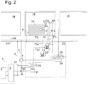
- Fig. 2 shows a simplified variant of the heating system. Same components as in the Fig. 1 are here provided with the same reference numerals and will be explained again only insofar as their arrangement or operation of that of the Fig. 1 differ.
- the switch 27 is arranged here at the output of the first controller 23 and in the heating operation, the setpoint temperature T2s, in Auskühlvermeidungs congress the target temperature T3s as a target value to the controller 24, so that this detected by the temperature sensor 17 in the heating temperature T2i to the setpoint T2s, in Chilling prevention operation on T3s controls.
- the temperature sensor 19 is omitted; his task is taken over by the temperature sensor 17.
Landscapes
- Engineering & Computer Science (AREA)
- Physics & Mathematics (AREA)
- Thermal Sciences (AREA)
- Chemical & Material Sciences (AREA)
- Combustion & Propulsion (AREA)
- Mechanical Engineering (AREA)
- General Engineering & Computer Science (AREA)
- Remote Sensing (AREA)
- General Physics & Mathematics (AREA)
- Automation & Control Theory (AREA)
- Steam Or Hot-Water Central Heating Systems (AREA)
Claims (16)
- Système de chauffage ayant au moins un premier capteur de température (16) pour capter une température ambiante (T1i) d'une pièce à chauffer (14), au moins une vanne (12) pour contrôler le flux d'un fluide caloporteur à travers un échangeur de chaleur (13) par rapport à des commandes d'ajustage, et un circuit de régulation (22), connecté au premier capteur de température (16) et à la vanne (12), pour produire les commandes d'ajustage, le circuit de régulation (22) étant connecté à un deuxième capteur de température (19) qui est positionné pour capter une première température (T3i) du fluide caloporteur après que ce dernier soit passé à travers au moins une partie de l'échangeur de chaleur (13), caractérisé en ce que le circuit de régulation est conçu pour produire les commandes d'ajustage en utilisant la première température (T3i) comme grandeur de régulation quand la température ambiante (T1i) est au-dessus d'une valeur de température ambiante souhaitée (T1s).
- Système de chauffage selon la revendication 1, caractérisé en ce que le circuit de régulation (22) est aussi conçu pour produire les commandes d'ajustage utilisant la première température (T3i) comme grandeur de régulation quand la première température (T3i) tombe au-dessous d'une valeur seuil.
- Système de chauffage selon la revendication 1 ou 2, caractérisé en ce que le deuxième capteur de température (19) est positionné au niveau d'une sortie de l'échangeur de chaleur (13).
- Système de chauffage selon la revendication 1, 2 ou 3, caractérisé en ce que le circuit de régulation est conçu pour utiliser la température ambiante (T1i) comme une grandeur de régulation quand la température ambiante (T1i) est au-dessous de la valeur de température ambiante souhaitée (T1s).
- Système de chauffage selon l'une quelconque des revendications précédentes, caractérisé en ce qu'une valeur souhaitée (T3s) pour la première température peut être réglée par un utilisateur.
- Système de chauffage selon l'une quelconque des revendications précédentes, caractérisé en ce que le circuit de régulation (22) comprend un premier régulateur (23) pour définir une valeur souhaitée (T2s) pour une deuxième température du fluide caloporteur par rapport à la température ambiante (T1i), et un deuxième régulateur (24) pour produire les commandes d'ajustage utilisant comme grandeur de régulation la deuxième température (T2i) captée.
- Système de chauffage selon la revendication 6, caractérisé en ce qu'un troisième capteur de température (17) pour capter la deuxième température (T2i) du fluide caloporteur en amont du deuxième capteur de température (19) est prévu sur l'échangeur de chaleur (13) ou sur un tuyau d'entrée (4) situé en amont de l'échangeur de chaleur (13) .
- Système de chauffage selon la revendication 6 ou 7, caractérisé en ce que le circuit de régulation (22) est aussi conçu pour produire les commandes d'ajustage en utilisant la première température (T3i) comme grandeur de régulation quand la deuxième température (T2i) tombe au-dessous d'une valeur seuil.
- Système de chauffage selon l'une quelconque des revendications 6 à 8, caractérisé en ce qu'au moins un des régulateurs (23, 24) a une composante intégrale.
- Système de chauffage selon l'une quelconque des revendications 6 à 9, caractérisé en ce que le circuit de régulation (22) est connecté à une source de chaleur (1) afin de réguler la température de sortie du fluide caloporteur distribué à partir de la source de chaleur (1) par rapport à la valeur souhaitée (T2s) pour la deuxième température du fluide caloporteur.
- Système de chauffage selon la revendication 10, caractérisé en ce que le circuit de régulation (22) est conçu pour augmenter la température de sortie si la valeur souhaitée pour la deuxième température (T2s) n'est pas atteinte avec la vanne (9) entièrement ouverte.
- Système de chauffage selon la revendication 10 ou 11, caractérisé en ce que le circuit de régulation (22) est connecté à une pluralité de premiers capteurs de température (16), et en ce qu'un premier régulateur (23) est associé à chacun des premiers capteurs de température (16) pour définir une valeur souhaitée (T2s) pour une deuxième température par rapport à la température ambiante (T1i) captée par ce premier capteur de température (16), et en ce que le circuit de régulation (22) est conçu pour réguler la température de sortie par rapport à la valeur souhaitée la plus haute (T2s) définie pour la deuxième température.
- Système de chauffage selon l'une quelconque des revendications précédentes, caractérisé en ce qu'il comprend une pluralité de vannes (9) pour contrôler le flux du fluide caloporteur à travers les échangeurs de chaleur respectifs (13) associés aux vannes (9), et une pompe de circulation (7) est éteinte chaque fois que toutes les vannes (9) sont fermées.
- Système de chauffage selon l'une quelconque des revendications précédentes, caractérisé en ce qu'il comprend une pluralité de vannes (9) pour contrôler le flux du fluide caloporteur à travers les échangeurs de chaleur respectifs (13) associés aux vannes (9), et en ce que le circuit de régulation (22) est conçu pour capter le degré d'ouverture de chaque vanne (9) séparément et pour contrôler la puissance de la pompe de circulation (7) par rapport aux degrés d'ouverture des vannes (9).
- Procédé de fonctionnement d'un système de chauffage ayant les étapes suivantes :le captage d'une température ambiante d'une pièce à chauffer,le captage d'une première température d'un fluide caloporteur après le passage de ce dernier à travers au moins une partie d'un échangeur de chaleur,caractérisé parquand la température ambiante est au-dessus d'une valeur souhaitée pour la température ambiante, le contrôle du flux d'un fluide caloporteur à travers l'échangeur de chaleur en utilisant la première température comme grandeur de régulation.
- Produit de programme d'ordinateur ayant des moyens de code de programme qui permettent à un ordinateur de fonctionner comme le circuit de régulation du système de chauffage selon l'une des revendications 1 à 14, ou de réaliser le procédé selon la revendication 15.
Applications Claiming Priority (2)
| Application Number | Priority Date | Filing Date | Title |
|---|---|---|---|
| DE102013012080.2A DE102013012080A1 (de) | 2013-07-22 | 2013-07-22 | Heizsystem und Betriebsverfahren dafür |
| PCT/EP2014/001964 WO2015010779A2 (fr) | 2013-07-22 | 2014-07-18 | Système de chauffage et procédé de fonctionnement de ce système |
Publications (2)
| Publication Number | Publication Date |
|---|---|
| EP3025100A2 EP3025100A2 (fr) | 2016-06-01 |
| EP3025100B1 true EP3025100B1 (fr) | 2018-01-10 |
Family
ID=51352484
Family Applications (1)
| Application Number | Title | Priority Date | Filing Date |
|---|---|---|---|
| EP14750692.7A Active EP3025100B1 (fr) | 2013-07-22 | 2014-07-18 | Système de chauffage et procédé de fonctionnement de ce système |
Country Status (3)
| Country | Link |
|---|---|
| EP (1) | EP3025100B1 (fr) |
| DE (1) | DE102013012080A1 (fr) |
| WO (1) | WO2015010779A2 (fr) |
Families Citing this family (1)
| Publication number | Priority date | Publication date | Assignee | Title |
|---|---|---|---|---|
| DE102020200057A1 (de) * | 2020-01-07 | 2021-07-08 | Robert Bosch Gesellschaft mit beschränkter Haftung | Verfahren zum Temperieren eines Gebäudes |
Family Cites Families (3)
| Publication number | Priority date | Publication date | Assignee | Title |
|---|---|---|---|---|
| DE10338868A1 (de) * | 2003-08-20 | 2005-03-17 | Vertrieb und Großhandel von Heizungs-, Sanitär- und Elektroerzeugnissen | Verfahren und Einrichtung zur Anpassung der Vorlauftemperatur eines Wärmeerzeugers an die jeweilige Heizkreisbelastung einer nachgeschalteten Heizungsanlage |
| NL1025309C2 (nl) * | 2004-01-23 | 2005-07-26 | Nedap Nv | Systeem voor het onafhankelijk regelen van de temperaturen in verschillende ruimten en van de temperaturen van één of meerdere warmwaterboilers. |
| DE202011101087U1 (de) * | 2011-05-25 | 2011-07-14 | Wolfgang Buttner | Thermostat für Heizkörperventile mit 2 Funktionen |
-
2013
- 2013-07-22 DE DE102013012080.2A patent/DE102013012080A1/de not_active Withdrawn
-
2014
- 2014-07-18 EP EP14750692.7A patent/EP3025100B1/fr active Active
- 2014-07-18 WO PCT/EP2014/001964 patent/WO2015010779A2/fr active Application Filing
Also Published As
| Publication number | Publication date |
|---|---|
| WO2015010779A3 (fr) | 2015-04-09 |
| DE102013012080A1 (de) | 2015-01-22 |
| EP3025100A2 (fr) | 2016-06-01 |
| WO2015010779A2 (fr) | 2015-01-29 |
Similar Documents
| Publication | Publication Date | Title |
|---|---|---|
| EP3593055B1 (fr) | Procédé pour faire fonctionner une installation de chauffage | |
| EP1606556B1 (fr) | Procede pour assurer le reglage de plusieurs echangeurs de chaleur couples en parallele | |
| EP2960587B1 (fr) | Procédé de limitation du débit d'alimentation dans un système de transmission de chaleur | |
| DE112009000227T5 (de) | Klimaanlagensteuersystem | |
| DE102012002941B4 (de) | Verfahren zum Betrieb einer Heizungs- oder Kühlanlage sowie Heizungs- und Kühlanlage | |
| DE69918379T2 (de) | Regelungssystem für die Heizung eines Gebäudes | |
| CH706736A1 (de) | Verfahren zum Betrieb eines Wärmetauschers sowie HVAC-Anlage zur Durchführung des Verfahrens. | |
| DE102010053211B4 (de) | Verfahren zum Betreiben und Einstellen der Wärmekurve eines Heizungssystems | |
| EP3443228A1 (fr) | Ensemble pompe centrifuge et procédé de réglage de son fonctionnement | |
| DE2843929A1 (de) | Anordnung zur steuerung der raumtemperatur | |
| EP2636959B1 (fr) | Réglage de radiateur | |
| EP3412978B1 (fr) | Procédé de commande d'un système de refroidissement et/ou de chauffage | |
| EP0062297A2 (fr) | Installation de chauffage et de ventilation | |
| EP3473939B1 (fr) | Procédé de fonctionnement d'une installation de chauffage et installation de chauffage | |
| WO2008080508A1 (fr) | Système de régulation thermostatique et procédé pour le fonctionnement des modes de chauffage et de refroidissement d'un tel système de régulation thermostatique | |
| DE3036661A1 (de) | Zentrale warmwasserheizungsanlage | |
| EP3025100B1 (fr) | Système de chauffage et procédé de fonctionnement de ce système | |
| WO2003023288A1 (fr) | Installation de chauffage central | |
| DE10259279B3 (de) | Versorgungssystem für Heiz-oder Kühlwasser sowie Verfahren zum Betreiben desselben | |
| DE102010056301A1 (de) | Verfahren zur automatischen Optimierung eines Heizsystems sowie Heizsystem | |
| DE2553380A1 (de) | Klimaanlage | |
| DE102012101850A1 (de) | Verfahren zur bedarfsgeführten Regelung eines Wärmeerzeugers in einer Heizungsanlage | |
| DE10151346C1 (de) | Raum-Aufheizeinheit | |
| DE202022106303U1 (de) | Raumtemperatur-Regelung der Warmwasser-Fußbodenheizung als Input-Regelung | |
| EP4230921A1 (fr) | Procédé de commande d'une température ambiante, système de chauffage pour commander une température ambiante et dispositif de commande destiné à être utilisé dans un système de chauffage |
Legal Events
| Date | Code | Title | Description |
|---|---|---|---|
| PUAI | Public reference made under article 153(3) epc to a published international application that has entered the european phase |
Free format text: ORIGINAL CODE: 0009012 |
|
| 17P | Request for examination filed |
Effective date: 20160219 |
|
| AK | Designated contracting states |
Kind code of ref document: A2 Designated state(s): AL AT BE BG CH CY CZ DE DK EE ES FI FR GB GR HR HU IE IS IT LI LT LU LV MC MK MT NL NO PL PT RO RS SE SI SK SM TR |
|
| AX | Request for extension of the european patent |
Extension state: BA ME |
|
| DAX | Request for extension of the european patent (deleted) | ||
| GRAP | Despatch of communication of intention to grant a patent |
Free format text: ORIGINAL CODE: EPIDOSNIGR1 |
|
| STAA | Information on the status of an ep patent application or granted ep patent |
Free format text: STATUS: GRANT OF PATENT IS INTENDED |
|
| INTG | Intention to grant announced |
Effective date: 20170609 |
|
| GRAJ | Information related to disapproval of communication of intention to grant by the applicant or resumption of examination proceedings by the epo deleted |
Free format text: ORIGINAL CODE: EPIDOSDIGR1 |
|
| STAA | Information on the status of an ep patent application or granted ep patent |
Free format text: STATUS: REQUEST FOR EXAMINATION WAS MADE |
|
| GRAS | Grant fee paid |
Free format text: ORIGINAL CODE: EPIDOSNIGR3 |
|
| STAA | Information on the status of an ep patent application or granted ep patent |
Free format text: STATUS: GRANT OF PATENT IS INTENDED |
|
| INTC | Intention to grant announced (deleted) | ||
| GRAP | Despatch of communication of intention to grant a patent |
Free format text: ORIGINAL CODE: EPIDOSNIGR1 |
|
| GRAA | (expected) grant |
Free format text: ORIGINAL CODE: 0009210 |
|
| STAA | Information on the status of an ep patent application or granted ep patent |
Free format text: STATUS: THE PATENT HAS BEEN GRANTED |
|
| INTG | Intention to grant announced |
Effective date: 20171127 |
|
| AK | Designated contracting states |
Kind code of ref document: B1 Designated state(s): AL AT BE BG CH CY CZ DE DK EE ES FI FR GB GR HR HU IE IS IT LI LT LU LV MC MK MT NL NO PL PT RO RS SE SI SK SM TR |
|
| REG | Reference to a national code |
Ref country code: CH Ref legal event code: EP Ref country code: AT Ref legal event code: REF Ref document number: 962811 Country of ref document: AT Kind code of ref document: T Effective date: 20180115 |
|
| REG | Reference to a national code |
Ref country code: IE Ref legal event code: FG4D Free format text: LANGUAGE OF EP DOCUMENT: GERMAN |
|
| REG | Reference to a national code |
Ref country code: DE Ref legal event code: R096 Ref document number: 502014006903 Country of ref document: DE |
|
| REG | Reference to a national code |
Ref country code: NL Ref legal event code: MP Effective date: 20180110 |
|
| PG25 | Lapsed in a contracting state [announced via postgrant information from national office to epo] |
Ref country code: NL Free format text: LAPSE BECAUSE OF FAILURE TO SUBMIT A TRANSLATION OF THE DESCRIPTION OR TO PAY THE FEE WITHIN THE PRESCRIBED TIME-LIMIT Effective date: 20180110 |
|
| PG25 | Lapsed in a contracting state [announced via postgrant information from national office to epo] |
Ref country code: ES Free format text: LAPSE BECAUSE OF FAILURE TO SUBMIT A TRANSLATION OF THE DESCRIPTION OR TO PAY THE FEE WITHIN THE PRESCRIBED TIME-LIMIT Effective date: 20180110 Ref country code: CY Free format text: LAPSE BECAUSE OF FAILURE TO SUBMIT A TRANSLATION OF THE DESCRIPTION OR TO PAY THE FEE WITHIN THE PRESCRIBED TIME-LIMIT Effective date: 20180110 Ref country code: FI Free format text: LAPSE BECAUSE OF FAILURE TO SUBMIT A TRANSLATION OF THE DESCRIPTION OR TO PAY THE FEE WITHIN THE PRESCRIBED TIME-LIMIT Effective date: 20180110 Ref country code: LT Free format text: LAPSE BECAUSE OF FAILURE TO SUBMIT A TRANSLATION OF THE DESCRIPTION OR TO PAY THE FEE WITHIN THE PRESCRIBED TIME-LIMIT Effective date: 20180110 Ref country code: HR Free format text: LAPSE BECAUSE OF FAILURE TO SUBMIT A TRANSLATION OF THE DESCRIPTION OR TO PAY THE FEE WITHIN THE PRESCRIBED TIME-LIMIT Effective date: 20180110 Ref country code: NO Free format text: LAPSE BECAUSE OF FAILURE TO SUBMIT A TRANSLATION OF THE DESCRIPTION OR TO PAY THE FEE WITHIN THE PRESCRIBED TIME-LIMIT Effective date: 20180410 |
|
| PG25 | Lapsed in a contracting state [announced via postgrant information from national office to epo] |
Ref country code: PL Free format text: LAPSE BECAUSE OF FAILURE TO SUBMIT A TRANSLATION OF THE DESCRIPTION OR TO PAY THE FEE WITHIN THE PRESCRIBED TIME-LIMIT Effective date: 20180110 Ref country code: RS Free format text: LAPSE BECAUSE OF FAILURE TO SUBMIT A TRANSLATION OF THE DESCRIPTION OR TO PAY THE FEE WITHIN THE PRESCRIBED TIME-LIMIT Effective date: 20180110 Ref country code: BG Free format text: LAPSE BECAUSE OF FAILURE TO SUBMIT A TRANSLATION OF THE DESCRIPTION OR TO PAY THE FEE WITHIN THE PRESCRIBED TIME-LIMIT Effective date: 20180410 Ref country code: GR Free format text: LAPSE BECAUSE OF FAILURE TO SUBMIT A TRANSLATION OF THE DESCRIPTION OR TO PAY THE FEE WITHIN THE PRESCRIBED TIME-LIMIT Effective date: 20180411 Ref country code: SE Free format text: LAPSE BECAUSE OF FAILURE TO SUBMIT A TRANSLATION OF THE DESCRIPTION OR TO PAY THE FEE WITHIN THE PRESCRIBED TIME-LIMIT Effective date: 20180110 Ref country code: IS Free format text: LAPSE BECAUSE OF FAILURE TO SUBMIT A TRANSLATION OF THE DESCRIPTION OR TO PAY THE FEE WITHIN THE PRESCRIBED TIME-LIMIT Effective date: 20180510 Ref country code: LV Free format text: LAPSE BECAUSE OF FAILURE TO SUBMIT A TRANSLATION OF THE DESCRIPTION OR TO PAY THE FEE WITHIN THE PRESCRIBED TIME-LIMIT Effective date: 20180110 |
|
| PG25 | Lapsed in a contracting state [announced via postgrant information from national office to epo] |
Ref country code: MT Free format text: LAPSE BECAUSE OF FAILURE TO SUBMIT A TRANSLATION OF THE DESCRIPTION OR TO PAY THE FEE WITHIN THE PRESCRIBED TIME-LIMIT Effective date: 20180110 |
|
| REG | Reference to a national code |
Ref country code: DE Ref legal event code: R097 Ref document number: 502014006903 Country of ref document: DE |
|
| PG25 | Lapsed in a contracting state [announced via postgrant information from national office to epo] |
Ref country code: RO Free format text: LAPSE BECAUSE OF FAILURE TO SUBMIT A TRANSLATION OF THE DESCRIPTION OR TO PAY THE FEE WITHIN THE PRESCRIBED TIME-LIMIT Effective date: 20180110 Ref country code: IT Free format text: LAPSE BECAUSE OF FAILURE TO SUBMIT A TRANSLATION OF THE DESCRIPTION OR TO PAY THE FEE WITHIN THE PRESCRIBED TIME-LIMIT Effective date: 20180110 Ref country code: AL Free format text: LAPSE BECAUSE OF FAILURE TO SUBMIT A TRANSLATION OF THE DESCRIPTION OR TO PAY THE FEE WITHIN THE PRESCRIBED TIME-LIMIT Effective date: 20180110 Ref country code: EE Free format text: LAPSE BECAUSE OF FAILURE TO SUBMIT A TRANSLATION OF THE DESCRIPTION OR TO PAY THE FEE WITHIN THE PRESCRIBED TIME-LIMIT Effective date: 20180110 |
|
| PLBE | No opposition filed within time limit |
Free format text: ORIGINAL CODE: 0009261 |
|
| STAA | Information on the status of an ep patent application or granted ep patent |
Free format text: STATUS: NO OPPOSITION FILED WITHIN TIME LIMIT |
|
| PG25 | Lapsed in a contracting state [announced via postgrant information from national office to epo] |
Ref country code: DK Free format text: LAPSE BECAUSE OF FAILURE TO SUBMIT A TRANSLATION OF THE DESCRIPTION OR TO PAY THE FEE WITHIN THE PRESCRIBED TIME-LIMIT Effective date: 20180110 Ref country code: SM Free format text: LAPSE BECAUSE OF FAILURE TO SUBMIT A TRANSLATION OF THE DESCRIPTION OR TO PAY THE FEE WITHIN THE PRESCRIBED TIME-LIMIT Effective date: 20180110 Ref country code: CZ Free format text: LAPSE BECAUSE OF FAILURE TO SUBMIT A TRANSLATION OF THE DESCRIPTION OR TO PAY THE FEE WITHIN THE PRESCRIBED TIME-LIMIT Effective date: 20180110 Ref country code: SK Free format text: LAPSE BECAUSE OF FAILURE TO SUBMIT A TRANSLATION OF THE DESCRIPTION OR TO PAY THE FEE WITHIN THE PRESCRIBED TIME-LIMIT Effective date: 20180110 |
|
| 26N | No opposition filed |
Effective date: 20181011 |
|
| PG25 | Lapsed in a contracting state [announced via postgrant information from national office to epo] |
Ref country code: SI Free format text: LAPSE BECAUSE OF FAILURE TO SUBMIT A TRANSLATION OF THE DESCRIPTION OR TO PAY THE FEE WITHIN THE PRESCRIBED TIME-LIMIT Effective date: 20180110 |
|
| REG | Reference to a national code |
Ref country code: CH Ref legal event code: PL |
|
| GBPC | Gb: european patent ceased through non-payment of renewal fee |
Effective date: 20180718 |
|
| PG25 | Lapsed in a contracting state [announced via postgrant information from national office to epo] |
Ref country code: LU Free format text: LAPSE BECAUSE OF NON-PAYMENT OF DUE FEES Effective date: 20180718 Ref country code: MC Free format text: LAPSE BECAUSE OF FAILURE TO SUBMIT A TRANSLATION OF THE DESCRIPTION OR TO PAY THE FEE WITHIN THE PRESCRIBED TIME-LIMIT Effective date: 20180110 |
|
| REG | Reference to a national code |
Ref country code: CH Ref legal event code: AECN Free format text: DAS PATENT WURDE AUFGRUND DES WEITERBEHANDLUNGSANTRAGS VOM 27.03.2019 REAKTIVIERT. |
|
| REG | Reference to a national code |
Ref country code: BE Ref legal event code: MM Effective date: 20180731 |
|
| REG | Reference to a national code |
Ref country code: IE Ref legal event code: MM4A |
|
| PG25 | Lapsed in a contracting state [announced via postgrant information from national office to epo] |
Ref country code: IE Free format text: LAPSE BECAUSE OF NON-PAYMENT OF DUE FEES Effective date: 20180718 Ref country code: GB Free format text: LAPSE BECAUSE OF NON-PAYMENT OF DUE FEES Effective date: 20180718 Ref country code: FR Free format text: LAPSE BECAUSE OF NON-PAYMENT OF DUE FEES Effective date: 20180731 |
|
| PGFP | Annual fee paid to national office [announced via postgrant information from national office to epo] |
Ref country code: CH Payment date: 20190327 Year of fee payment: 5 |
|
| PG25 | Lapsed in a contracting state [announced via postgrant information from national office to epo] |
Ref country code: BE Free format text: LAPSE BECAUSE OF NON-PAYMENT OF DUE FEES Effective date: 20180731 |
|
| REG | Reference to a national code |
Ref country code: CH Ref legal event code: PL |
|
| PG25 | Lapsed in a contracting state [announced via postgrant information from national office to epo] |
Ref country code: TR Free format text: LAPSE BECAUSE OF FAILURE TO SUBMIT A TRANSLATION OF THE DESCRIPTION OR TO PAY THE FEE WITHIN THE PRESCRIBED TIME-LIMIT Effective date: 20180110 |
|
| PG25 | Lapsed in a contracting state [announced via postgrant information from national office to epo] |
Ref country code: PT Free format text: LAPSE BECAUSE OF FAILURE TO SUBMIT A TRANSLATION OF THE DESCRIPTION OR TO PAY THE FEE WITHIN THE PRESCRIBED TIME-LIMIT Effective date: 20180110 Ref country code: CH Free format text: LAPSE BECAUSE OF NON-PAYMENT OF DUE FEES Effective date: 20190731 Ref country code: LI Free format text: LAPSE BECAUSE OF NON-PAYMENT OF DUE FEES Effective date: 20190731 |
|
| PG25 | Lapsed in a contracting state [announced via postgrant information from national office to epo] |
Ref country code: MK Free format text: LAPSE BECAUSE OF NON-PAYMENT OF DUE FEES Effective date: 20180110 Ref country code: HU Free format text: LAPSE BECAUSE OF FAILURE TO SUBMIT A TRANSLATION OF THE DESCRIPTION OR TO PAY THE FEE WITHIN THE PRESCRIBED TIME-LIMIT; INVALID AB INITIO Effective date: 20140718 |
|
| REG | Reference to a national code |
Ref country code: AT Ref legal event code: MM01 Ref document number: 962811 Country of ref document: AT Kind code of ref document: T Effective date: 20190718 |
|
| PG25 | Lapsed in a contracting state [announced via postgrant information from national office to epo] |
Ref country code: AT Free format text: LAPSE BECAUSE OF NON-PAYMENT OF DUE FEES Effective date: 20190718 |
|
| PGFP | Annual fee paid to national office [announced via postgrant information from national office to epo] |
Ref country code: DE Payment date: 20230731 Year of fee payment: 10 |