EP3024983B1 - Self-propelled apparatus for measuring geometric and/or structural parameters of a railway track and/or switch - Google Patents
Self-propelled apparatus for measuring geometric and/or structural parameters of a railway track and/or switch Download PDFInfo
- Publication number
- EP3024983B1 EP3024983B1 EP14758667.1A EP14758667A EP3024983B1 EP 3024983 B1 EP3024983 B1 EP 3024983B1 EP 14758667 A EP14758667 A EP 14758667A EP 3024983 B1 EP3024983 B1 EP 3024983B1
- Authority
- EP
- European Patent Office
- Prior art keywords
- supporting frame
- lateral
- wheels
- switch
- central
- Prior art date
- Legal status (The legal status is an assumption and is not a legal conclusion. Google has not performed a legal analysis and makes no representation as to the accuracy of the status listed.)
- Active
Links
Images




Classifications
-
- B—PERFORMING OPERATIONS; TRANSPORTING
- B61—RAILWAYS
- B61K—AUXILIARY EQUIPMENT SPECIALLY ADAPTED FOR RAILWAYS, NOT OTHERWISE PROVIDED FOR
- B61K9/00—Railway vehicle profile gauges; Detecting or indicating overheating of components; Apparatus on locomotives or cars to indicate bad track sections; General design of track recording vehicles
- B61K9/08—Measuring installations for surveying permanent way
Definitions
- the present invention relates to a self-propelled apparatus for measuring geometric and/or structural parameters of a railway track and/or switch.
- German Patent Application DE-OS- 21 30 385 discloses a mobile track survey apparatus for measuring the gauge of a track.
- the apparatus is provided with a carriage for being movable on the rails in the direction of track elongation.
- the track gauge is measured by two rail sensing elements which are biased in opposite directions against the respective track rails. The lateral movement of the sensing elements in respect of each other is converted into electrical signal proportional to this movement, and this signal is transmitted to a signal indicator or recorder.
- the aim of the present invention is to provide a self-propelled apparatus to measure geometric and/or structural parameters of a railway track and/or switch that will be free from the drawbacks described above and that will be simple and economically advantageous to produce.
- a self-propelled apparatus to measure geometric and/or structural parameters of a railway track and/or switch is provided as specified in the annexed claims.
- a self-propelled apparatus for the measuring of geometric and/or structural parameters of a railway track and/or switch designated by 80 and referred to hereinafter as "track" for simplicity.
- the apparatus 1 comprises a motor-driven carriage 2 designed to be coupled, in use, with the track 80, and an electronic measuring module 3 mounted on the carriage 2 to measure at least one geometric and/or structural parameter of the track 80 while the carriage 2 is moving, in use, along the track 80.
- the carriage 2 is shaped like an H, and comprises two mutually parallel trains 4 of wheels, which have an elongated shape, extend in a substantially horizontal direction 5, and are each designed to be coupled to a respective rail 81 of the track 80.
- the two trains 4 of wheels are connected to one another by a central supporting frame 6, which has an elongated shape, and extends in a substantially horizontal direction 7 transverse to the direction 5.
- the trains of wheels 4 are designed to couple to the rails 81 in a direction 7 transverse, and in particular perpendicular, to the rails 81.
- the carriage 2 further has two mutually parallel protection buffers 8 ( Figure 1 ), each of which extends in the direction 7 and is engaged at the free ends of the two trains 4 of wheels to guarantee safety for the operators.
- the frame 6 comprises a central body 9 having a rectangular shape, and two side appendages 10, which are shaped like a rectangular annulus and are arranged on opposite sides of the body 9 in the direction 7 so as to arrange themselves, in use, above a corresponding rail 81.
- Each appendage 10 is slidably coupled to the body 9 via a bar 10a engaged in a pair of guides 10b ( Figure 7 ) and a coupling roller 11 ( Figure 8 ) rotatably mounted on a respective supporting bracket 12 projecting from the appendage 10 within the body 9 in the direction 7.
- the roller 11 is mounted to turn about an axis 13 of rotation parallel to the direction 5 and is slidably engaged in a respective eyelet 14 made through the body 9 in the direction 7.
- roller 11 of one appendage 10 has a diameter substantially equal to a height of the corresponding eyelet 14, whereas the roller 11 of the other appendage 10 has a diameter approximating by defect the height of the corresponding eyelet 14 so as to enable the appendage 10 itself to oscillate, with respect to the body 9, about a longitudinal axis 15 ( Figure 7 ) parallel to the direction 7 and to the trains 4 of wheels to adapt to those stretches of the track 80 in which the rails 81 are not perfectly flat.
- each appendage 10 from the body 9 in the direction 7 is adjustable via a respective screw/female-screw coupling ( Figure 7 ) constituted by a screw 16 mounted on the body 9 and a corresponding female screw 17 ( Figure 7 ) mounted at one end of the bar 10a of the appendage 10.
- the two screw/female-screw couplings 16, 17 have respective directions of thread opposite to one another.
- the screws 16 and the respective female screws 17 define part of an actuation device 18, further comprising a pulley 19 rigidly coupled to the two screws 16 and an electric motor 45 ( Figure 3 ), which is connected to the pulley 19 via a belt transmission 46 ( Figure 3 ) to set the screws 16 in rotation so as to impart on the appendages 10 rectilinear displacements in opposite senses in the direction 7.
- the position of the appendages 10 with respect to the central body 9 in the direction 7 is detected via a position sensor 20.
- the latter is constituted by a linear-sliding potentiometer having a resistive bar 20a fixed on the body 9, parallel to the direction 7, and a slider 20b fixed to the internal screw 17 of one of the two appendages 10 by means of a bracket 17a so as to slide, in use, along the resistive bar 20b following upon displacement of the appendage 10 with respect to the body 9. Since the dimensions of the appendages 10 and of the lateral supporting frames 31 in the direction 7 are known beforehand, the signal supplied by the position sensor 20 indicates the distance between the two trains of wheels 4 in the direction 7, i.e., the wheel gauge of the carriage 2.
- the position of the appendages 10 with respect to the central body 9 in the direction 7 is detected via a rotation sensor designed to detect rotation of the screws.
- Each appendage 10 is further provided with a pair of supporting feet 21, which are mounted on opposite sides of the appendage 10 in the direction 5, and are hinged to the appendage 10 to turn about an axis of fulcrum 22 parallel to the direction 5 itself between an operating position, where the feet 21 project downwards from the appendage 10, and a resting position, where the feet 21 are substantially contained within the appendage 10 itself.
- each appendage 10 is displaced between the corresponding operative positions and the corresponding resting positions via a crank mechanism 23 comprising a crank 24 hinged to the appendage 10 so as to turn about an axis of fulcrum 25 parallel to the direction 5, and two rockers 26 coupled in an angularly fixed way to the crank 24.
- Each rocker 26 is displaced by the crank 24 about the axis 25, and is connected to a corresponding connecting rod 27, which extends between two axes 28, 29 of rotation parallel to one another and to the direction 5, and where the axis 28 is the axis of rotation of the connecting rod 27 with respect to a first arm 26a of the rocker 26 and the axis 29 is the axis of rotation of the connecting rod 27 with respect to the corresponding foot 21.
- the position of the axes 22, 25, 28, and 29 is such as to define a toggle mechanism, which is stabilized in the operative positions of the feet 21 by a pair of springs 30 interposed between the appendage 10 and the corresponding feet 21 so as to enable the feet 21 to displace into their resting positions only following upon actuation of the crank 24.
- each train 4 of wheels comprises a lateral supporting frame 31, which extends in the direction 5 and supports a plurality of wheels 32 for advance of the carriage, in the case in point two pairs of wheels 32 arranged on opposite sides of the frame 6, and in particular on opposite sides, in the direction 5, of the corresponding appendage 10.
- the wheels 32 of each pair of wheels 32 are coupled to one another via a belt transmission 33, and are arranged, in use, in contact with a top surface of the corresponding rail 81 of the track 80.
- only one pair of wheels 32 is driven by a motor 32a and the other pair of wheels 32 is provided with an encoder (not illustrated).
- the frame 31 further supports a plurality of guide rollers 34 (in the case in point four rollers 34), which project downwards from the frame 31, are rotatably coupled to the frame 31 so as to turn idle, with respect to the frame 31, about respective longitudinal axes 35 parallel to a vertical direction 36 orthogonal to the directions 5 and 7, and are arranged, in use, in contact with or in the proximity of an internal surface of the corresponding rail 81 of the track 80.
- guide rollers 34 in the case in point four rollers 34
- the supporting frame 31 comprises a central rectangular edge or frame 37, which projects from the supporting frame 31 in the direction 7, is arranged on a corresponding appendage 10, and extends about a corresponding crank 24.
- each frame 37 is substantially aligned with the annular rectangular shape of the corresponding appendage 10 in order to define, together with the latter, an opening 37a from which, in use, the corresponding rail 81 is visible from above.
- the frame 37 and then the train 4 of wheels, is releasably engaged to the supporting frame 6 via an engagement device 38 comprising a pair of vertical-pin elements 39 and a pair of horizontal-pin elements 40.
- the elements 39 project downwards from the frame 37 in the direction 36, are substantially U-shaped, and are slidably coupled to respective slits 41 made through the corresponding appendage 10 in the direction 7 so as to co-operate with respective engagement pins 41a mounted within the slits 41 themselves.
- the elements 40 project from the frame 37 in the direction 7 and slidably engage respective holes 42 made through the corresponding appendage 10 in the direction 7 itself.
- the frame 37 and, then, the supporting frame 31 are mobile between a position of engagement of the train 4 of wheels to the supporting frame 6 and a position of release of the train 4 of wheels from the supporting frame 6 under the thrust of the crank 24.
- the arms 26b co-operate with the corresponding slots 43 so as to move the frame 31 closer to the body 9, engage the elements 39 in the corresponding pins 41a and the elements 40 in the corresponding holes 42, and then engage the train 4 of wheels to the frame 6.
- the arms 26b co-operate with the corresponding slots 43 so as to move the frame 31 away from the frame 6, disengage the elements 40 from the corresponding holes 42, and then release the train 4 of wheels from the frame 6.
- assembly of the apparatus 1 is carried out by displacing the feet 21 into their operative positions, leaning the feet 21 on the track 80, engaging the two trains 4 of wheels to the frame 6, moving again the feet 21 into their resting positions so as to couple the wheels 32 to the track 80, and mounting the measuring module 3 on four supporting pins 44 projecting upwards from the body 9 in the direction 36.
- conformation of the engagement devices 38 enables a unique assembly of each train 4 of wheels on the frame 6.
- Dismantling of the apparatus 1 is obviously carried out following an operating sequence opposite to the one described above.
- the carriage 2 and the measuring device 3 are supplied electrically via one or more batteries (not illustrated).
- the carriage 2 may be easily dismantled and assembled, has relatively low weights and small overall dimensions, and enables a simple and convenient transfer, for example a manual transfer, of the apparatus 1 from one railway line to another.
- the possibility of adjusting the distance of the appendages 10 and, then, of the trains 4 of wheels, with respect to the central body 9 in the direction 7 enables real-time control of the distance between the two trains 4 of wheels as a function the width of the track 80.
- the measuring module 3 comprises an outer shell 47, which is substantially parallelepipedal in shape and is mounted on the pins 44, and two laser profilometers 48, one for each train of wheels 4, which are arranged within the shell 47 and are designed to acquire video images of the top part of the corresponding rail 81.
- Each laser profilometer 48 comprises a laser source 49, which is designed to project, through a respective opening (not illustrated) made in the bottom of the shell 47, a laser curtain 50 transverse to the direction 5 so as to be oriented, in use, onto the corresponding rail 81, and a video camera 51, which is oriented so as to frame the aforesaid opening of the bottom of the shell 47 with its own optical axis 52 oblique with respect to the plane in which the laser curtain 50 lies for acquiring video images of the light contour generated by the laser curtain 50 on the top surface of the corresponding rail 81.
- the laser curtain 50 is perpendicular to the direction 5. According to a variant not illustrated of the present invention, it is the optical axis 52, and not the laser curtain 50, that is perpendicular to the direction 5.
- Each of said openings on the bottom of the shell 47 is aligned with a corresponding opening 37a ( Figure 2 ).
- each laser curtain 50 after exiting from the corresponding bottom opening of the shell 47, traverses the access opening 37a and impinges upon the surface of the rail 81, and the corresponding video camera 51 is able to frame, through the access opening 37a, the rail 81 at the light contour generated by the laser curtain 50 on the rail 81.
- the two laser profilometers 48 are fixed with respect to the shell 47, and then with respect to the central supporting frame 6, with their optical axes 52 parallel to a plane that is transverse to the direction 7 and parallel to the direction 5.
- the distance between the axes 52 is designated by DL.
- the measuring module 3 further comprises a processing and control unit 53, which is provided in the form of one or more electronic boards, is also arranged within the shell 47, and is configured for processing the video images acquired by the two laser profilometers 48 in order to measure the structural parameters of the track 80 and to control the actuation device 18 as a function the video images acquired and of the signal supplied by the position sensor 20 in order to adapt the wheel gauge of the carriage 2 to the variations of gauge of the track 80.
- a processing and control unit 53 which is provided in the form of one or more electronic boards, is also arranged within the shell 47, and is configured for processing the video images acquired by the two laser profilometers 48 in order to measure the structural parameters of the track 80 and to control the actuation device 18 as a function the video images acquired and of the signal supplied by the position sensor 20 in order to adapt the wheel gauge of the carriage 2 to the variations of gauge of the track 80.
- the processing and control unit 53 is configured for determining, in real time, the top profile of each rail 81 from the video images acquired by the corresponding laser profilometer 48, the current gauge of the track 80 as a function of the top profiles of the two rails 81 and the distance DL, and the current wheel gauge of the carriage 2 as a function of the signal supplied by the position sensor 20, and for controlling the motor 45 of the actuation device 18 so as to reduce the difference between the current wheel gauge of the carriage 2 and the current gauge of the track 80.
- the processing and control unit 53 controls in real time adjustment of the wheel gauge of the carriage 2 for tracking and compensating the variations in gauge of the track 80.
- Real-time adjustment of the wheel gauge of the carriage 2 enables increase in the precision of measurement of the structural parameters of the track 80.
- only one of the two appendages 10 is slidably coupled to the central body 9, and the actuation device 18 comprises a single external-screw/internal-screw coupling, said internal screw 17 being mounted on the slidable appendage 10.
- the apparatus 1 according to this embodiment is simpler to produce and is a bit lighter, but has a lower measuring capacity, in the sense that it is more likely for some parts of the rail 81 under the mobile appendage 10 to exit from the field of view of the video camera 51 that is arranged in a position corresponding to the mobile appendage 10.
- the rail 81 under the fixed appendage 10 is always well framed by the corresponding video camera 51, whereas the other rail 81 has a greater likelihood of ending up, at least partially, out of the field of view of the other video camera 51 when the gauge of the track 80 increases.
- the appendages 10 are coupled in a fixed way to the central body 9, and the guide rollers 34 are mounted on the corresponding supporting frames 31, not only in a rotatable way about the axes 35, but also slidably in the direction 7.
- the guide rollers 34 are mounted on the corresponding supporting frames 31, not only in a rotatable way about the axes 35, but also slidably in the direction 7.
- the wheels 32 In order to prevent the carriage 2 from derailing from the track 80, the wheels 32 must being oversized in width with respect to the embodiment illustrated.
- the carriage 2 comprises, instead of the actuation device 18, an actuation system having one or more electric motors for imparting on the guide rollers 34 rectilinear displacements in the direction 7 and, instead of the position sensor 20, one or more position sensors connected between the guide rollers 34 and the corresponding supporting frame 31 to detect the position of the guide rollers 34 in the direction 7.
- the processing and control unit 53 is configured for controlling the actuation system as a function of the video images acquired and of the signals supplied by the position sensors in order to adapt the wheel gauge of the carriage 2 to the variations of gauge of the track 80.
- the actuation system imparts on the guide rollers 34 of a train of wheels 4 displacements that are symmetrical, i.e., of the same amount and opposite, to the ones imparted on the guide rollers 34 of the other train of wheels 4.
- the actuation system comprises at least two motors for imparting on the two series of guide rollers 34 of the two trains of wheels 4 mutually independent displacements.
- the processing and control unit 53 is configured for controlling independently the two motors of the actuation system so as to allow the possibility of adapting the field of view of just one video camera 51, and then the range of measurement of the corresponding laser profilometer 48, in particular situations of use, for example along asymmetric stretches of the railway track (with or without switches).
- measurements along a stretch of the track 80 may be made by making two passes to and from along the stretch of the track 80 and controlling the guide rollers 34 of the two trains of wheels 4 in a symmetrical way in the forward movement and in an asymmetrical way in the backward movement in order to vary the field of view of at least one video camera 51 for said stretch and thus increase the measuring capacity of the measuring module 3.
- Figures 9 and 10 illustrate a carriage 54, which differs from the carriage 2 illustrated in Figures 2 and 3 substantially in that the four guide rollers 34 of each frame 31 are replaced with two guide assemblies 55, each of which is mounted between two respective wheels 32.
- each guide assembly 55 comprises a rocker 56, which is pivoted on the frame 31 so as to oscillate, with respect to the frame 31 itself, about an axis of fulcrum 57 parallel to the direction 5, and has a first arm 58 projecting downwards in the direction 36 and a second arm 59 extending in the direction 7.
- the arm 58 is traversed by a threaded pin 60, which has a longitudinal axis 61 substantially parallel to the direction 7, and is rotatably engaged, via interposition of a pair of rolling bearings 62, through a driving roller 63.
- the roller 63 faces the other frame 31, has a substantially frustoconical shape, and is mounted idle on the pin 60 so as to turn about the axis 61.
- the roller 63 has a lateral surface 64 that has a crowned profile and faces the arm 58 for coupling, in use, with an inner side 82 of the top profile of a corresponding rail 81.
- the pin 60 projects from the roller 63 in the direction 7, and carries connected thereto a guide bar 65, which extends in the direction 5, is mounted on a supporting bracket 66 fixed to a free end of the pin 60, and is shaped in such a way as to facilitate coupling of the roller 63 with the corresponding rail 81 and favour entry of the roller 63 into the railway switches that it may encounter along the track 80.
- the arm 59 extends within the frame 31, and supports an end-of-stroke block 67, which is made, in the case in point, of plastic material, and is rotatably coupled to the free end of the arm 59 so as to oscillate, with respect to the arm 59 itself, about an axis of fulcrum 68 parallel to the direction 5.
- the end-of-stroke block 67 is provided with a screw 69 made of metal material, which is screwed in the end-of-stroke block 67 itself parallel to the direction 36, and gives out towards the outside of the frame 31 through an opening 70 made in the frame 31 itself.
- the screw 69 defines part of a detection device 71, which is designed to detect the position of the rocker 56 about the axis 57 and further comprises an end-of-stroke sensor 72 fixed to the frame 31 parallel to the direction 36.
- the rocker 56 is mobile about the axis 57 between a first position, where the end-of-stroke block 67 comes to bear upon a surface portion 70a of the frame 31 around the opening 70 and the screw 69 comes into contact with the sensor 72, and a second position, where the end-of-stroke block 67 is arranged at a certain distance from the surface portion 70a and the screw 69 is arranged at a certain distance from the sensor 72 itself.
- the sensor 72 has the purpose of detecting contact with the screw 69, i.e., of detecting when the screw 69 goes into the end-of-stroke position.
- the screw 69 may be replaced with a different metal element that may be detected by the sensor 62.
- the corresponding guide bar 65 When the rocker 56 is in its first position, the corresponding guide bar 65 is set at the maximum distance from the opposite frame 31. When, instead, the rocker 56 is in its second position, the corresponding guide bar 65 approaches the opposite frame 31, i.e., is set at a distance from the opposite frame 31 shorter than said maximum distance.
- the rocker 56 is displaced into, and normally kept in, its first position by a spring 73, which extends in the direction 36, is mounted on the opposite side of the screw 69 with respect to the axis 68, and is interposed between the frame 31 and the arm 59.
- the rocker 56 of one or more guide assemblies 55 shifts into its second position against the action of the spring 73, and the corresponding sensor 72 signals the absence of end-of-stroke.
- the processing and control unit 53 is configured for processing signals supplied by the end-of-stroke sensors 72 in order to detect and warn of anomalous situations during advance of the carriage 54 on the track 80 or else during adjustment of the wheel gauge of the carriage 54.
- anomalous situations that may be detected are the following:
Landscapes
- Engineering & Computer Science (AREA)
- Mechanical Engineering (AREA)
- Length Measuring Devices With Unspecified Measuring Means (AREA)
- Machines For Laying And Maintaining Railways (AREA)
Description
- The present invention relates to a self-propelled apparatus for measuring geometric and/or structural parameters of a railway track and/or switch.
- In the field of self-propelled apparatuses for the measuring of geometric and/or structural parameters of a railway track and/or switch, it is known to provide a motor-driven railway carriage provided with a measuring device to measure at least one geometric and/or structural parameter of the railway track and/or switch.
- Known self-propelled apparatuses to measure geometric and/or structural parameters of a railway track and/or switch of the type described above present some drawbacks mainly deriving from the fact that the aforesaid railway bogies are relatively cumbersome, heavy, and costly, entail serious operating difficulties for their transfer from one railway line to another, and are then not suited to being used in a simple and flexible way. In fact, use of the aforesaid railway bogies calls for relatively long manoeuvring times and the availability of relatively long stretches of railway track and/or the presence of corresponding switches, and then involves prolonged interruptions of normal circulation of trains. Furthermore, the relatively heavy weight of railway bogies may lead to deformation of the corresponding rolling structures that come into contact with the railway track and/or switch, jeopardizing proper measurement of the geometric and/or structural parameters of the railway track and/or switch itself.
- Finally, known self-propelled apparatuses are unable to make measurements with high precision, above all where the switches are located, on account of their poor capacity for adaptation to the inevitable variability of the distance between the rails of the track.
- German Patent Application
DE-OS- 21 30 385 - The aim of the present invention is to provide a self-propelled apparatus to measure geometric and/or structural parameters of a railway track and/or switch that will be free from the drawbacks described above and that will be simple and economically advantageous to produce.
- According to the present invention, a self-propelled apparatus to measure geometric and/or structural parameters of a railway track and/or switch is provided as specified in the annexed claims.
- The present invention will now be described with reference to the annexed drawings, which illustrate a non-limiting example of embodiment thereof and in which:
-
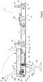
Figure 1 is a schematic perspective view of a preferred embodiment of the apparatus according to the present invention; -
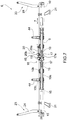
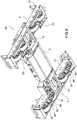
Figures 2 and3 are two schematic perspective views of a detail of the apparatus ofFigure 1 ; -
Figure 4 is an exploded perspective view of the detail ofFigures 2 and3 ; -
Figures 5 and6 are two schematic side views, with parts in cross section and parts removed for reasons of clarity, of a detail ofFigures 2 and3 illustrated in two different operative positions; -
Figures 7 and8 are two schematic side views, with parts in cross section and parts removed for reasons of clarity, of a detail ofFigures 5 and6 ; -
Figure 9 is similar toFigure 3 and is a schematic perspective view of a variant of the detail ofFigures 2 and3 ; and -
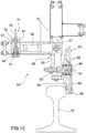
Figure 10 is a schematic side view, with parts in cross section and parts removed for reasons of clarity, of a detail ofFigure 9 . - With reference to
Figure 1 , designated as a whole by 1 is a self-propelled apparatus for the measuring of geometric and/or structural parameters of a railway track and/or switch, designated by 80 and referred to hereinafter as "track" for simplicity. - The
apparatus 1 comprises a motor-drivencarriage 2 designed to be coupled, in use, with thetrack 80, and an electronic measuring module 3 mounted on thecarriage 2 to measure at least one geometric and/or structural parameter of thetrack 80 while thecarriage 2 is moving, in use, along thetrack 80. - According to what is illustrated in
Figures 2 and3 , thecarriage 2 is shaped like an H, and comprises two mutuallyparallel trains 4 of wheels, which have an elongated shape, extend in a substantiallyhorizontal direction 5, and are each designed to be coupled to arespective rail 81 of thetrack 80. The twotrains 4 of wheels are connected to one another by a central supportingframe 6, which has an elongated shape, and extends in a substantiallyhorizontal direction 7 transverse to thedirection 5. The trains ofwheels 4 are designed to couple to therails 81 in adirection 7 transverse, and in particular perpendicular, to therails 81. - The
carriage 2 further has two mutually parallel protection buffers 8 (Figure 1 ), each of which extends in thedirection 7 and is engaged at the free ends of the twotrains 4 of wheels to guarantee safety for the operators. - With reference to
Figures 3 ,4 ,7 , and8 , theframe 6 comprises acentral body 9 having a rectangular shape, and twoside appendages 10, which are shaped like a rectangular annulus and are arranged on opposite sides of thebody 9 in thedirection 7 so as to arrange themselves, in use, above acorresponding rail 81. - Each
appendage 10 is slidably coupled to thebody 9 via abar 10a engaged in a pair ofguides 10b (Figure 7 ) and a coupling roller 11 (Figure 8 ) rotatably mounted on a respective supportingbracket 12 projecting from theappendage 10 within thebody 9 in thedirection 7. - The
roller 11 is mounted to turn about anaxis 13 of rotation parallel to thedirection 5 and is slidably engaged in a respective eyelet 14 made through thebody 9 in thedirection 7. - In this connection, it should be pointed out that the
roller 11 of oneappendage 10 has a diameter substantially equal to a height of the corresponding eyelet 14, whereas theroller 11 of theother appendage 10 has a diameter approximating by defect the height of the corresponding eyelet 14 so as to enable theappendage 10 itself to oscillate, with respect to thebody 9, about a longitudinal axis 15 (Figure 7 ) parallel to thedirection 7 and to thetrains 4 of wheels to adapt to those stretches of thetrack 80 in which therails 81 are not perfectly flat. - The distance of each
appendage 10 from thebody 9 in thedirection 7 is adjustable via a respective screw/female-screw coupling (Figure 7 ) constituted by ascrew 16 mounted on thebody 9 and a corresponding female screw 17 (Figure 7 ) mounted at one end of thebar 10a of theappendage 10. The two screw/female-screw couplings - The
screws 16 and the respectivefemale screws 17 define part of anactuation device 18, further comprising apulley 19 rigidly coupled to the twoscrews 16 and an electric motor 45 (Figure 3 ), which is connected to thepulley 19 via a belt transmission 46 (Figure 3 ) to set thescrews 16 in rotation so as to impart on theappendages 10 rectilinear displacements in opposite senses in thedirection 7. - The position of the
appendages 10 with respect to thecentral body 9 in thedirection 7 is detected via aposition sensor 20. The latter is constituted by a linear-sliding potentiometer having aresistive bar 20a fixed on thebody 9, parallel to thedirection 7, and a slider 20b fixed to theinternal screw 17 of one of the twoappendages 10 by means of abracket 17a so as to slide, in use, along the resistive bar 20b following upon displacement of theappendage 10 with respect to thebody 9. Since the dimensions of theappendages 10 and of the lateral supportingframes 31 in thedirection 7 are known beforehand, the signal supplied by theposition sensor 20 indicates the distance between the two trains ofwheels 4 in thedirection 7, i.e., the wheel gauge of thecarriage 2. - According to a variant (not illustrated) of the present invention, the position of the
appendages 10 with respect to thecentral body 9 in thedirection 7 is detected via a rotation sensor designed to detect rotation of the screws. - Each
appendage 10 is further provided with a pair of supportingfeet 21, which are mounted on opposite sides of theappendage 10 in thedirection 5, and are hinged to theappendage 10 to turn about an axis offulcrum 22 parallel to thedirection 5 itself between an operating position, where thefeet 21 project downwards from theappendage 10, and a resting position, where thefeet 21 are substantially contained within theappendage 10 itself. - The
feet 21 of eachappendage 10 are displaced between the corresponding operative positions and the corresponding resting positions via acrank mechanism 23 comprising acrank 24 hinged to theappendage 10 so as to turn about an axis offulcrum 25 parallel to thedirection 5, and tworockers 26 coupled in an angularly fixed way to thecrank 24. - Each
rocker 26 is displaced by thecrank 24 about theaxis 25, and is connected to acorresponding connecting rod 27, which extends between twoaxes direction 5, and where theaxis 28 is the axis of rotation of the connectingrod 27 with respect to afirst arm 26a of therocker 26 and theaxis 29 is the axis of rotation of the connectingrod 27 with respect to thecorresponding foot 21. - The position of the
axes feet 21 by a pair ofsprings 30 interposed between theappendage 10 and thecorresponding feet 21 so as to enable thefeet 21 to displace into their resting positions only following upon actuation of thecrank 24. - According to what is illustrated in
Figure 3 , eachtrain 4 of wheels comprises a lateral supportingframe 31, which extends in thedirection 5 and supports a plurality ofwheels 32 for advance of the carriage, in the case in point two pairs ofwheels 32 arranged on opposite sides of theframe 6, and in particular on opposite sides, in thedirection 5, of thecorresponding appendage 10. Thewheels 32 of each pair ofwheels 32 are coupled to one another via abelt transmission 33, and are arranged, in use, in contact with a top surface of thecorresponding rail 81 of thetrack 80. For eachtrain 4 of wheels, only one pair ofwheels 32 is driven by amotor 32a and the other pair ofwheels 32 is provided with an encoder (not illustrated). - The
frame 31 further supports a plurality of guide rollers 34 (in the case in point four rollers 34), which project downwards from theframe 31, are rotatably coupled to theframe 31 so as to turn idle, with respect to theframe 31, about respectivelongitudinal axes 35 parallel to avertical direction 36 orthogonal to thedirections corresponding rail 81 of thetrack 80. - With reference to
Figures 2 ,4 ,5 , and6 , the supportingframe 31 comprises a central rectangular edge orframe 37, which projects from the supportingframe 31 in thedirection 7, is arranged on acorresponding appendage 10, and extends about acorresponding crank 24. As may be appreciated fromFigure 2 , eachframe 37 is substantially aligned with the annular rectangular shape of thecorresponding appendage 10 in order to define, together with the latter, an opening 37a from which, in use, thecorresponding rail 81 is visible from above. - The
frame 37, and then thetrain 4 of wheels, is releasably engaged to the supportingframe 6 via anengagement device 38 comprising a pair of vertical-pin elements 39 and a pair of horizontal-pin elements 40. - The
elements 39 project downwards from theframe 37 in thedirection 36, are substantially U-shaped, and are slidably coupled torespective slits 41 made through thecorresponding appendage 10 in thedirection 7 so as to co-operate withrespective engagement pins 41a mounted within theslits 41 themselves. - The
elements 40 project from theframe 37 in thedirection 7 and slidably engagerespective holes 42 made through thecorresponding appendage 10 in thedirection 7 itself. - The
frame 37 and, then, the supportingframe 31 are mobile between a position of engagement of thetrain 4 of wheels to the supportingframe 6 and a position of release of thetrain 4 of wheels from the supportingframe 6 under the thrust of thecrank 24. - Rotation of the
crank 24, obtained by displacing thefeet 21 from the operative positions into the resting positions, leads to rotation of therockers 26 about theaxis 25 and engagement of asecond arm 26b of eachrocker 26 in acorresponding slot 43 made through theframe 37 in thedirection 7. - The
arms 26b co-operate with thecorresponding slots 43 so as to move theframe 31 closer to thebody 9, engage theelements 39 in thecorresponding pins 41a and theelements 40 in thecorresponding holes 42, and then engage thetrain 4 of wheels to theframe 6. - The opposite rotation of the
crank 24, obtained by displacing thefeet 21 from the resting positions into the operative positions, leads to rotation of therockers 26 about theaxis 25 and disengagement of thesecond arm 26b of eachrocker 26 from thecorresponding slot 43. - In this case, the
arms 26b co-operate with thecorresponding slots 43 so as to move theframe 31 away from theframe 6, disengage theelements 40 from thecorresponding holes 42, and then release thetrain 4 of wheels from theframe 6. - In this connection, it should be pointed out that, when the
feet 21 are arranged in their operating position, they project downwards from thewheels 32. - From what has been set forth above, it thus follows that assembly of the
apparatus 1 is carried out by displacing thefeet 21 into their operative positions, leaning thefeet 21 on thetrack 80, engaging the twotrains 4 of wheels to theframe 6, moving again thefeet 21 into their resting positions so as to couple thewheels 32 to thetrack 80, and mounting the measuring module 3 on four supportingpins 44 projecting upwards from thebody 9 in thedirection 36. It should be noted that the conformation of theengagement devices 38 enables a unique assembly of eachtrain 4 of wheels on theframe 6. - Dismantling of the
apparatus 1 is obviously carried out following an operating sequence opposite to the one described above. - Finally, it should be pointed out that the
carriage 2 and the measuring device 3 are supplied electrically via one or more batteries (not illustrated). - Since the two
trains 4 of wheels are releasably engaged to the central supportingframe 6, thecarriage 2 may be easily dismantled and assembled, has relatively low weights and small overall dimensions, and enables a simple and convenient transfer, for example a manual transfer, of theapparatus 1 from one railway line to another. - Furthermore, the possibility of adjusting the distance of the
appendages 10 and, then, of thetrains 4 of wheels, with respect to thecentral body 9 in thedirection 7 enables real-time control of the distance between the twotrains 4 of wheels as a function the width of thetrack 80. - In this connection, with reference once again to
Figure 1 , the measuring module 3 comprises anouter shell 47, which is substantially parallelepipedal in shape and is mounted on thepins 44, and twolaser profilometers 48, one for each train ofwheels 4, which are arranged within theshell 47 and are designed to acquire video images of the top part of the correspondingrail 81. - Each
laser profilometer 48 comprises alaser source 49, which is designed to project, through a respective opening (not illustrated) made in the bottom of theshell 47, alaser curtain 50 transverse to thedirection 5 so as to be oriented, in use, onto the correspondingrail 81, and avideo camera 51, which is oriented so as to frame the aforesaid opening of the bottom of theshell 47 with its ownoptical axis 52 oblique with respect to the plane in which thelaser curtain 50 lies for acquiring video images of the light contour generated by thelaser curtain 50 on the top surface of the correspondingrail 81. - In the example illustrated in
Figure 1 , thelaser curtain 50 is perpendicular to thedirection 5. According to a variant not illustrated of the present invention, it is theoptical axis 52, and not thelaser curtain 50, that is perpendicular to thedirection 5. - Each of said openings on the bottom of the
shell 47 is aligned with acorresponding opening 37a (Figure 2 ). In this way, eachlaser curtain 50, after exiting from the corresponding bottom opening of theshell 47, traverses the access opening 37a and impinges upon the surface of therail 81, and thecorresponding video camera 51 is able to frame, through the access opening 37a, therail 81 at the light contour generated by thelaser curtain 50 on therail 81. - The two
laser profilometers 48 are fixed with respect to theshell 47, and then with respect to the central supportingframe 6, with theiroptical axes 52 parallel to a plane that is transverse to thedirection 7 and parallel to thedirection 5. InFigure 1 , the distance between theaxes 52 is designated by DL. - The measuring module 3 further comprises a processing and
control unit 53, which is provided in the form of one or more electronic boards, is also arranged within theshell 47, and is configured for processing the video images acquired by the twolaser profilometers 48 in order to measure the structural parameters of thetrack 80 and to control theactuation device 18 as a function the video images acquired and of the signal supplied by theposition sensor 20 in order to adapt the wheel gauge of thecarriage 2 to the variations of gauge of thetrack 80. - In particular, the processing and
control unit 53 is configured for determining, in real time, the top profile of eachrail 81 from the video images acquired by thecorresponding laser profilometer 48, the current gauge of thetrack 80 as a function of the top profiles of the tworails 81 and the distance DL, and the current wheel gauge of thecarriage 2 as a function of the signal supplied by theposition sensor 20, and for controlling themotor 45 of theactuation device 18 so as to reduce the difference between the current wheel gauge of thecarriage 2 and the current gauge of thetrack 80. In other words, the processing andcontrol unit 53 controls in real time adjustment of the wheel gauge of thecarriage 2 for tracking and compensating the variations in gauge of thetrack 80. - Real-time adjustment of the wheel gauge of the
carriage 2 enables increase in the precision of measurement of the structural parameters of thetrack 80. - According to a further embodiment (not illustrated) of the present invention, only one of the two
appendages 10 is slidably coupled to thecentral body 9, and theactuation device 18 comprises a single external-screw/internal-screw coupling, saidinternal screw 17 being mounted on theslidable appendage 10. Theapparatus 1 according to this embodiment is simpler to produce and is a bit lighter, but has a lower measuring capacity, in the sense that it is more likely for some parts of therail 81 under themobile appendage 10 to exit from the field of view of thevideo camera 51 that is arranged in a position corresponding to themobile appendage 10. In fact, therail 81 under the fixedappendage 10 is always well framed by the correspondingvideo camera 51, whereas theother rail 81 has a greater likelihood of ending up, at least partially, out of the field of view of theother video camera 51 when the gauge of thetrack 80 increases. - According to a further embodiment (not illustrated) of the present invention, the
appendages 10 are coupled in a fixed way to thecentral body 9, and theguide rollers 34 are mounted on the corresponding supportingframes 31, not only in a rotatable way about theaxes 35, but also slidably in thedirection 7. In this way, it is possible to adjust the distance between theguide rollers 34 of one train ofwheels 4 with theguide rollers 34 of the other train ofwheels 4 and then, in practice, adjust the effective wheel gauge of thecarriage 2. In order to prevent thecarriage 2 from derailing from thetrack 80, thewheels 32 must being oversized in width with respect to the embodiment illustrated. - According to the latter embodiment, the
carriage 2 comprises, instead of theactuation device 18, an actuation system having one or more electric motors for imparting on theguide rollers 34 rectilinear displacements in thedirection 7 and, instead of theposition sensor 20, one or more position sensors connected between theguide rollers 34 and the corresponding supportingframe 31 to detect the position of theguide rollers 34 in thedirection 7. The processing andcontrol unit 53 is configured for controlling the actuation system as a function of the video images acquired and of the signals supplied by the position sensors in order to adapt the wheel gauge of thecarriage 2 to the variations of gauge of thetrack 80. Furthermore, the actuation system imparts on theguide rollers 34 of a train ofwheels 4 displacements that are symmetrical, i.e., of the same amount and opposite, to the ones imparted on theguide rollers 34 of the other train ofwheels 4. - According to a variant of the latter embodiment described above, the actuation system comprises at least two motors for imparting on the two series of
guide rollers 34 of the two trains ofwheels 4 mutually independent displacements. The processing andcontrol unit 53 is configured for controlling independently the two motors of the actuation system so as to allow the possibility of adapting the field of view of just onevideo camera 51, and then the range of measurement of thecorresponding laser profilometer 48, in particular situations of use, for example along asymmetric stretches of the railway track (with or without switches). For example, measurements along a stretch of thetrack 80 may be made by making two passes to and from along the stretch of thetrack 80 and controlling theguide rollers 34 of the two trains ofwheels 4 in a symmetrical way in the forward movement and in an asymmetrical way in the backward movement in order to vary the field of view of at least onevideo camera 51 for said stretch and thus increase the measuring capacity of the measuring module 3. -
Figures 9 and10 illustrate acarriage 54, which differs from thecarriage 2 illustrated inFigures 2 and3 substantially in that the fourguide rollers 34 of eachframe 31 are replaced with twoguide assemblies 55, each of which is mounted between tworespective wheels 32. - With particular reference to
Figure 10 , eachguide assembly 55 comprises arocker 56, which is pivoted on theframe 31 so as to oscillate, with respect to theframe 31 itself, about an axis offulcrum 57 parallel to thedirection 5, and has afirst arm 58 projecting downwards in thedirection 36 and asecond arm 59 extending in thedirection 7. - The
arm 58 is traversed by a threadedpin 60, which has alongitudinal axis 61 substantially parallel to thedirection 7, and is rotatably engaged, via interposition of a pair of rollingbearings 62, through a drivingroller 63. - The
roller 63 faces theother frame 31, has a substantially frustoconical shape, and is mounted idle on thepin 60 so as to turn about theaxis 61. In particular, theroller 63 has alateral surface 64 that has a crowned profile and faces thearm 58 for coupling, in use, with aninner side 82 of the top profile of a correspondingrail 81. - The
pin 60 projects from theroller 63 in thedirection 7, and carries connected thereto aguide bar 65, which extends in thedirection 5, is mounted on a supportingbracket 66 fixed to a free end of thepin 60, and is shaped in such a way as to facilitate coupling of theroller 63 with the correspondingrail 81 and favour entry of theroller 63 into the railway switches that it may encounter along thetrack 80. - The
arm 59 extends within theframe 31, and supports an end-of-stroke block 67, which is made, in the case in point, of plastic material, and is rotatably coupled to the free end of thearm 59 so as to oscillate, with respect to thearm 59 itself, about an axis offulcrum 68 parallel to thedirection 5. - The end-of-
stroke block 67 is provided with ascrew 69 made of metal material, which is screwed in the end-of-stroke block 67 itself parallel to thedirection 36, and gives out towards the outside of theframe 31 through anopening 70 made in theframe 31 itself. - The
screw 69 defines part of adetection device 71, which is designed to detect the position of therocker 56 about theaxis 57 and further comprises an end-of-stroke sensor 72 fixed to theframe 31 parallel to thedirection 36. - The
rocker 56 is mobile about theaxis 57 between a first position, where the end-of-stroke block 67 comes to bear upon a surface portion 70a of theframe 31 around theopening 70 and thescrew 69 comes into contact with thesensor 72, and a second position, where the end-of-stroke block 67 is arranged at a certain distance from the surface portion 70a and thescrew 69 is arranged at a certain distance from thesensor 72 itself. Then, thesensor 72 has the purpose of detecting contact with thescrew 69, i.e., of detecting when thescrew 69 goes into the end-of-stroke position. Obviously, thescrew 69 may be replaced with a different metal element that may be detected by thesensor 62. - When the
rocker 56 is in its first position, thecorresponding guide bar 65 is set at the maximum distance from theopposite frame 31. When, instead, therocker 56 is in its second position, thecorresponding guide bar 65 approaches theopposite frame 31, i.e., is set at a distance from theopposite frame 31 shorter than said maximum distance. - The
rocker 56 is displaced into, and normally kept in, its first position by aspring 73, which extends in thedirection 36, is mounted on the opposite side of thescrew 69 with respect to theaxis 68, and is interposed between theframe 31 and thearm 59. - When, in use, the gauge of the
track 80 narrows excessively with respect to the wheel gauge of thecarriage 54, therocker 56 of one ormore guide assemblies 55 shifts into its second position against the action of thespring 73, and the correspondingsensor 72 signals the absence of end-of-stroke. - The processing and
control unit 53 is configured for processing signals supplied by the end-of-stroke sensors 72 in order to detect and warn of anomalous situations during advance of thecarriage 54 on thetrack 80 or else during adjustment of the wheel gauge of thecarriage 54. - For example, some anomalous situations that may be detected are the following:
- yaw of the
carriage 54 during advance on thetrack 80, when thesensors 72 corresponding to just two diagonally opposite guide assemblies 55 (for example, the front right one and the rear left one) detect the end-of-stroke; - impact of the
carriage 54 with an obstacle on arail 81, when only onesensor 72 does not detect the end-of-stroke, i.e., thesensor 72 of theguide assembly 55 theroller 63 of which undergoes impact; - anomalous narrowing of the
track 80, when thesensors 72 of two or threeguide assemblies 55 do not detect the end-of-stroke; and - excessive widening of the wheel gauge of the
carriage 54 controlled by the wheel-gauge adjustment system, when thesensors 72 of at least two transversely opposite guide assemblies 55 (i.e., the front ones and/or the rear ones) do not detect the end-of-stroke.
Claims (20)
- A self-propelled apparatus for measuring geometric and/or structural parameters of a railway track and/or switch (80), the apparatus comprising a motor-driven carriage (2; 54) designed to be coupled, in use, to the railway track and/or switch, and a measuring module (3) mounted on the carriage (2; 54) to measure at least one of said geometric and/or structural parameters of the railway track and/or switch (80); the carriage (2; 54) comprising a central supporting frame or structure (6) extending in a substantially horizontal direction transverse to the direction of the track and two trains of wheels (4), which are carried by the central supporting frame (6) and are each coupleable to a respective rail (81) of the railway track and/or switch (80); the apparatus being characterized in that each train of wheels (4) comprises a lateral supporting frame or structure (31) and a plurality of wheels (32) for advance of the carriage, which are rotatably mounted on the lateral supporting frame (31), and an engagement device (38) for releasably engaging the lateral supporting frame (31) to the central supporting frame (6).
- The apparatus according to Claim 1, wherein each of said central and lateral supporting frames (6, 31) has an elongated shape; the central supporting frame (6) extending transverse to said lateral supporting frames (31).
- The apparatus according to Claim 1 or Claim 2, wherein each engagement device (38) comprises coupling means (39, 40) between the central supporting frame (6) and the corresponding lateral supporting frame (31) and actuation means (23) for displacing the coupling means (39, 40) between a position of engagement of the corresponding lateral supporting frame (31) to the central supporting frame (6) and a position of release.
- The apparatus according to Claim 3, wherein the central supporting frame (6) extends in a first direction (7) and wherein said lateral supporting frames (31) extend in a second direction (5) transverse to the first direction (7); said coupling means (39, 40) being mobile in the first direction (7) between said positions of engagement and release.
- The apparatus according to Claim 4, wherein each lateral supporting frame (31) is mobile in the first direction (7) for displacing the corresponding coupling means (39, 40) between said positions of engagement and release.
- The apparatus according to Claim 4 or Claim 5, wherein the coupling means (39, 40) comprise first pin means (40) parallel to the first direction (7) and second pin means (39) parallel to a third direction (36) substantially orthogonal to said first and second directions (7, 5); the second pin means (39) being mobile between said positions of engagement and release along at least one channel of advance (41) substantially parallel to the first direction (7).
- The apparatus according to any one of Claims 3 to 6, wherein the actuation means (23) comprise at least one drawing member (26b), which is mounted on the central supporting frame (6) and is designed to engage a seat (43) made in the corresponding lateral supporting frame (31) for displacing the corresponding lateral supporting frame (31) between said positions of engagement and release.
- The apparatus according to any one of the preceding claims, wherein the central supporting frame (6) is provided with at least one pair of supporting feet (21), each of which is mobile between a corresponding operating position, where the supporting foot (21) projects downwards from the central supporting frame (6), in particular downwards from the advancing wheels (32), to lean on the corresponding rail (81), and a corresponding resting position, where the supporting foot (21) is substantially contained within the central supporting frame (6).
- The apparatus according to Claim 8 when it depends upon any one of Claims 3 to 7, wherein each supporting foot (21) is connected to said actuation means (23) to be displaced by the actuation means (23) themselves between the corresponding operating position and the corresponding resting position.
- The apparatus according to any one of the preceding claims, wherein the central supporting frame (6) comprises a central body (9) and two lateral appendages (10), which are engaged, in use, to the corresponding lateral supporting frames (31) and are mobile with respect to the central body (9) for controlling selectively the distance between the two trains of wheels (4).
- The apparatus according to claim 1, wherein the central supporting frame (6) comprises a central body (9) and two lateral appendages (10), at least one first of which is coupled in a mobile way to the central body (9) to slide in a first rectilinear direction (7) transverse to the railway track and/or switch (80); the lateral supporting frame (31) being engaged to a respective lateral appendage (10); the carriage (2; 54) comprising motor-driven actuation means (18) for moving the first lateral appendage (10) in the first direction (7) in order to adjust the wheel gauge of the carriage (2; 54); the measuring module (3)being an electronic measuring module and comprising at least two laser profilometers (48) for acquiring, each, video images of the top part of a respective rail (81) and processing and control means (53) configured for controlling the actuation means (18) as a function of said video images so as to adapt the wheel gauge in real time to the variations of gauge of the railway track and/or switch (80), and preferably configured to measure said geometric and/or structural parameters of the railway track and/or switch (80) on the basis of processing of said video images.
- The apparatus according to Claim 11, wherein the carriage (2; 54) comprises position sensor means (20) for supplying a signal indicating the current position of the first lateral appendage (10) in the first direction (7), preferably the position sensor means comprising a linear-sliding potentiometer (20) having a resistive bar (20a) fixed on the central body (9), parallel to the first direction (7), and a slider (20b) fixed with respect to the first lateral appendage (10); the processing and control means (53) being configured for controlling the actuation means (18) as a function of said video images and of said signal so as to adapt the wheel gauge to the variations of gauge of the railway track and/or switch (80) .
- The apparatus according to Claim 11 or Claim 12, wherein said two laser profilometers (48) are arranged fixed with respect to the central supporting frame (6) with respective optical axes of acquisition (52) spaced apart, in a direction parallel to said first direction (7), by a pre-set distance (DL), and are each arranged in a position corresponding to a respective train of wheels (4) for acquiring video images of the corresponding rail (81).
- The apparatus according to Claim 13, wherein said processing and control means (53) are configured for controlling the actuation means (18) as a function of said video images and of said pre-set distance (DL) so as to adapt the wheel gauge to the variations of gauge of the railway track and/or switch (80).
- The apparatus according to Claim 13 or Claim 14, wherein each lateral appendage (10) is shaped like a rectangular annulus and is arranged, in use, above a corresponding rail (81), and each lateral supporting frame (31) comprises an outer edge or frame (37), which is arranged on top of, and substantially aligned with, a corresponding lateral appendage (10) so as to define, together with the latter, an opening (37a) from which a corresponding rail (81) is visible from above; each laser profilometer (48) being arranged on the corresponding frame (37) in such a way as to acquire video images of the corresponding rail (81) through said opening (37a) .
- The apparatus according to Claim 15, wherein each train of wheels (4) extends in a second direction (5) transverse to the first direction (7) and comprises two pairs of wheels (32), at least one pair of which is motor-driven and which are rotatably mounted on the corresponding lateral supporting frame (31) and are arranged on opposite sides, in the second direction (5), of the corresponding lateral appendage (10).
- The apparatus according to any one of Claims 11 to 16, wherein both of the lateral appendages (10) are coupled in a mobile way to the central body (9) so as to slide in the first direction (7); said actuation means (18) comprising a double screw/female-screw coupling (16, 17) that connects the central body (9) to the two lateral appendages (10), and an electric motor (45) for driving in rotation the double screw/female-screw coupling (16, 17) so as to impart on the lateral appendages (10) displacements in opposite senses in the first direction (7).
- The apparatus according to any one of Claims 11 to 17, wherein each train of wheels (4) extends in a second direction (5) transverse to the first direction (7) and comprises at least one guide assembly (55), which comprises: a respective rocker (56) pivoted on the corresponding lateral supporting frame (31) so as to oscillate about a first axis (57) parallel to the second direction (5); a guide roller (63), which is mounted idle on a first arm (59) of the rocker (56) to turn about a second axis (61) substantially parallel to the first direction (7) and is designed to couple with a corresponding rail (81) of said railway track and/or switch (80); a position-detecting device (71) coupled to a second arm (59) of the rocker (56) in such a way as to detect the position of the rocker (56) about the first axis (57); and elastic-return means (73) for displacing the rocker (56) into a pre-set position and normally keeping it there; said processing and control means (53) being configured for processing signals supplied by the position-detecting devices (71) in order to warn of anomalous situations regarding advance of the carriage (54) along the railway track and/or switch (80) and/or regarding control of said actuation means (18).
- The apparatus according to Claim 18, wherein said guide assembly (55) comprises an end-of-stroke block (67) designed to bear upon a surface portion (70a) of the corresponding lateral supporting frame (31) when said rocker (56) is in said pre-set position, and said position-detecting device (71) comprises an end-of-stroke sensor (72) fixed to the lateral supporting frame (31) in such a way as to detect said condition where said end-of-stroke block (57) bears upon said surface portion (70a).
- The apparatus according to claim 1, wherein, the lateral supporting frame (31) is engaged to the central supporting frame (6), the plurality of wheels (32) are motor-driven, and each train of wheels (32) comprises a series of guide rollers (34), which are mounted on the lateral supporting frame (31) so as to project downwards to come, in use, into contact with an internal surface of the corresponding rail (81) and are rotatably coupled to the supporting frame (31) to turn idle about respective vertical axes (35) and are slidably coupled in a rectilinear direction (7) transverse to the railway track and/or switch (80); the carriage (2; 54) comprising motor-driven actuation means for moving the guide rollers (34) in said direction (7) so as to adjust the distance between the two series of guide rollers (34); the measuring module (3)being an electronic measuring module and comprising at least two laser profilometers (48) for acquiring, each, video images of the top part of a respective rail (81), and processing and control means (53) configured for controlling the actuation means as a function of said video images so as to adapt in real time the distance between the two series of guide rollers (34) to the gauge of the railway track and/or switch (80); preferably the actuation means comprising at least two motors for imparting on said two series of guide rollers (34) mutually independent displacements and said processing and control means (53) being configured for controlling said two motors independently.
Applications Claiming Priority (3)
| Application Number | Priority Date | Filing Date | Title |
|---|---|---|---|
| IT000397A ITBO20130397A1 (en) | 2013-07-24 | 2013-07-24 | SELF PROPELLED EQUIPMENT FOR MEASURING GEOMETRIC AND / OR STRUCTURAL PARAMETERS OF A TRACK AND / OR RAILWAY EXCHANGE |
| IT000398A ITBO20130398A1 (en) | 2013-07-24 | 2013-07-24 | SELF PROPELLED EQUIPMENT FOR MEASURING GEOMETRIC AND / OR STRUCTURAL PARAMETERS OF A TRACK AND / OR RAILWAY EXCHANGE |
| PCT/IB2014/063392 WO2015011671A1 (en) | 2013-07-24 | 2014-07-24 | Self-propelled apparatus for measuring geometric and/or structural parameters of a railway track and/or switch |
Publications (2)
| Publication Number | Publication Date |
|---|---|
| EP3024983A1 EP3024983A1 (en) | 2016-06-01 |
| EP3024983B1 true EP3024983B1 (en) | 2020-07-01 |
Family
ID=51483632
Family Applications (1)
| Application Number | Title | Priority Date | Filing Date |
|---|---|---|---|
| EP14758667.1A Active EP3024983B1 (en) | 2013-07-24 | 2014-07-24 | Self-propelled apparatus for measuring geometric and/or structural parameters of a railway track and/or switch |
Country Status (4)
| Country | Link |
|---|---|
| EP (1) | EP3024983B1 (en) |
| JP (1) | JP6400704B2 (en) |
| ES (1) | ES2812610T3 (en) |
| WO (1) | WO2015011671A1 (en) |
Cited By (2)
| Publication number | Priority date | Publication date | Assignee | Title |
|---|---|---|---|---|
| CN111267884A (en) * | 2020-03-03 | 2020-06-12 | 成都圭目机器人有限公司 | Tunnel track inspection robot's mechanism of marcing |
| RU242488U1 (en) * | 2026-01-14 | 2026-03-26 | Акционерное общество "Фирма ТВЕМА" | OPTICAL PROFILOMETER FOR RAIL THREAD CONTROL |
Families Citing this family (10)
| Publication number | Priority date | Publication date | Assignee | Title |
|---|---|---|---|---|
| CN106274981B (en) * | 2016-09-30 | 2019-01-18 | 襄阳宏伟航空器有限责任公司 | A kind of track detection device and detection method |
| CN108995666B (en) * | 2017-06-07 | 2020-03-27 | 名硕电脑(苏州)有限公司 | Rail car and rail car wheel device thereof |
| CN107972696B (en) * | 2017-11-21 | 2019-08-23 | 南京擎华信息科技有限公司 | A kind of rail polling robot |
| CN110528345B (en) * | 2019-09-19 | 2021-02-19 | 无锡市妙图科技有限公司 | A self-propelled inspection vehicle for pre-delivery inspection of urban rail transit rails |
| CN112278008A (en) * | 2019-09-27 | 2021-01-29 | 宁波大桔科技有限公司 | Flaw detection method of steel rail flaw detection device for rail transit |
| CN110632273B (en) * | 2019-10-11 | 2020-11-10 | 义乌国信土地规划咨询有限公司 | A track bottom crack detection device |
| CN112921722A (en) * | 2021-03-01 | 2021-06-08 | 王龙贵 | Railway maintenance and repair device |
| CN114322805B (en) * | 2021-11-30 | 2023-12-26 | 杭州申昊科技股份有限公司 | Railway track space detection device |
| CN116620117B (en) * | 2023-04-13 | 2025-09-09 | 上海库赞轨道交通科技有限公司 | Intelligent abrasion detection device and detection method for rail transit rigid contact line |
| CN116353644B (en) * | 2023-05-31 | 2023-08-04 | 成都理工大学 | A monorail testing car suitable for track testing |
Citations (4)
| Publication number | Priority date | Publication date | Assignee | Title |
|---|---|---|---|---|
| US3405449A (en) * | 1967-01-17 | 1968-10-15 | New York Central Railroad Co | Rail track gauge |
| US5094004A (en) * | 1991-06-21 | 1992-03-10 | The United States Of America As Represented By The Secretary Of The Army | Railroad track gager/leveler/linear measurer |
| JPH07223539A (en) * | 1993-12-16 | 1995-08-22 | West Japan Railway Co | Simple track inspection vehicle and its dividing method |
| DE102006027852A1 (en) * | 2006-06-16 | 2007-12-20 | Geo Information Consult Gmbh | Track e.g. railroad track, measuring vehicle, has chassis with several wheels, where chassis has track width that is variably adjustable between five hundred and eighty millimeters and one thousand eight hundred and fifty millimeters |
Family Cites Families (13)
| Publication number | Priority date | Publication date | Assignee | Title |
|---|---|---|---|---|
| GB272070A (en) * | 1926-08-17 | 1927-06-09 | Joseph Piersaul | Improvements in or relating to track gauge & level indicating device |
| FR1418432A (en) * | 1963-11-29 | 1965-11-19 | Plasser Bahnbaumasch Franz | Device for vehicles for measuring or correcting the position of tracks or rails of a track |
| AT313345B (en) * | 1970-07-02 | 1974-02-11 | Plasser Bahnbaumasch Franz | Mobile device for determining the gauge of a track |
| JPS5142945A (en) * | 1974-10-11 | 1976-04-12 | Mitsubishi Electric Corp | Toraiatsuku nyoru hojikinotsukikoryusuitsuchikairo |
| JPS56153001A (en) * | 1980-04-24 | 1981-11-26 | Shibaura Eng Works Ltd | Apparatus for detecting obstacle splicing part in rail maitenance working machine |
| US4534296A (en) * | 1983-04-29 | 1985-08-13 | Southern Railway Company | Rail gauger |
| US4785589A (en) * | 1986-02-28 | 1988-11-22 | Les Fils D'auguste Scheuchzer S.A. | Process for measuring and grinding the profile of a rail head |
| JP2003207319A (en) * | 2002-01-10 | 2003-07-25 | Mitsubishi Heavy Ind Ltd | Sectional shape of rail measuring device |
| JP2005030858A (en) * | 2003-07-10 | 2005-02-03 | Sadao Abe | Creepage inspection/recording device for long rail |
| US8405837B2 (en) * | 2004-06-30 | 2013-03-26 | Georgetown Rail Equipment Company | System and method for inspecting surfaces using optical wavelength filtering |
| MXPA06015167A (en) * | 2004-06-30 | 2007-10-23 | Georgetown Rail Equipment Comp | System and method for inspecting railroad track. |
| US7659972B2 (en) * | 2007-08-22 | 2010-02-09 | Kld Labs, Inc. | Rail measurement system |
| US20120192756A1 (en) * | 2011-01-31 | 2012-08-02 | Harsco Corporation | Rail vision system |
-
2014
- 2014-07-24 WO PCT/IB2014/063392 patent/WO2015011671A1/en not_active Ceased
- 2014-07-24 ES ES14758667T patent/ES2812610T3/en active Active
- 2014-07-24 EP EP14758667.1A patent/EP3024983B1/en active Active
- 2014-07-24 JP JP2016528644A patent/JP6400704B2/en not_active Expired - Fee Related
Patent Citations (4)
| Publication number | Priority date | Publication date | Assignee | Title |
|---|---|---|---|---|
| US3405449A (en) * | 1967-01-17 | 1968-10-15 | New York Central Railroad Co | Rail track gauge |
| US5094004A (en) * | 1991-06-21 | 1992-03-10 | The United States Of America As Represented By The Secretary Of The Army | Railroad track gager/leveler/linear measurer |
| JPH07223539A (en) * | 1993-12-16 | 1995-08-22 | West Japan Railway Co | Simple track inspection vehicle and its dividing method |
| DE102006027852A1 (en) * | 2006-06-16 | 2007-12-20 | Geo Information Consult Gmbh | Track e.g. railroad track, measuring vehicle, has chassis with several wheels, where chassis has track width that is variably adjustable between five hundred and eighty millimeters and one thousand eight hundred and fifty millimeters |
Cited By (3)
| Publication number | Priority date | Publication date | Assignee | Title |
|---|---|---|---|---|
| CN111267884A (en) * | 2020-03-03 | 2020-06-12 | 成都圭目机器人有限公司 | Tunnel track inspection robot's mechanism of marcing |
| CN111267884B (en) * | 2020-03-03 | 2021-04-27 | 成都圭目机器人有限公司 | A traveling mechanism of a tunnel track detection robot |
| RU242488U1 (en) * | 2026-01-14 | 2026-03-26 | Акционерное общество "Фирма ТВЕМА" | OPTICAL PROFILOMETER FOR RAIL THREAD CONTROL |
Also Published As
| Publication number | Publication date |
|---|---|
| WO2015011671A1 (en) | 2015-01-29 |
| ES2812610T3 (en) | 2021-03-17 |
| EP3024983A1 (en) | 2016-06-01 |
| JP6400704B2 (en) | 2018-10-03 |
| JP2016525637A (en) | 2016-08-25 |
Similar Documents
| Publication | Publication Date | Title |
|---|---|---|
| EP3024983A1 (en) | Self-propelled apparatus for measuring geometric and/or structural parameters of a railway track and/or switch | |
| US5161312A (en) | Machine for monitoring the vertical position of a contact wire of an overhead line | |
| CN106829479B (en) | Vertical glass detection conveying table and detection method thereof | |
| CN106514919B (en) | A kind of plastic film is cast tensioning and the deviation-rectifying system of unit steel band | |
| EP3256812B1 (en) | Apparatus for measuring surface roughness of rail using acceleration sensor and displacement sensor | |
| KR100878204B1 (en) | Winding device of copper rolling mill | |
| ITMI982201A1 (en) | SYSTEM FOR THE MEASUREMENT OF RAILS, IN PARTICULAR SLIDING RAILS FOR CRANES, SHELVERS, BLOCKS OF BEARING WHEELS. | |
| CN108909204B (en) | Horizontal printing height difference deviation correcting device of color press | |
| CN106513442B (en) | A kind of high speed plate thickness measure and holding meanss | |
| CN104567776A (en) | Hard cable meter counting device | |
| KR101367300B1 (en) | Apparatus for aligning guide rollers | |
| CN220165528U (en) | Grid ruler mechanism for elevator speed measurement | |
| KR20220148598A (en) | Apparatus for detecting alignment state and method for detecting alignment state | |
| JP2007289662A5 (en) | ||
| CN113620136B (en) | Gravity self-driven elevator guide rail detection device | |
| CN205920042U (en) | Infrared surface fabric detection device | |
| CN203642897U (en) | Meter-counting device for small-section line | |
| CN110436140B (en) | Multifunctional belt conveyor test board | |
| KR101804386B1 (en) | Leveling apparatus and the method thereof | |
| CN216115966U (en) | Special detector for groove-shaped rail corrugation | |
| ITBO20130398A1 (en) | SELF PROPELLED EQUIPMENT FOR MEASURING GEOMETRIC AND / OR STRUCTURAL PARAMETERS OF A TRACK AND / OR RAILWAY EXCHANGE | |
| CN116675086B (en) | Elevator safety system and elevator safety control method | |
| CN216863139U (en) | Automatic fabric deviation correcting device of setting machine | |
| CN219830596U (en) | PVB film tension detects machine | |
| KR101354631B1 (en) | Battery shield for vinyl thickness measurement device |
Legal Events
| Date | Code | Title | Description |
|---|---|---|---|
| PUAI | Public reference made under article 153(3) epc to a published international application that has entered the european phase |
Free format text: ORIGINAL CODE: 0009012 |
|
| 17P | Request for examination filed |
Effective date: 20160122 |
|
| AK | Designated contracting states |
Kind code of ref document: A1 Designated state(s): AL AT BE BG CH CY CZ DE DK EE ES FI FR GB GR HR HU IE IS IT LI LT LU LV MC MK MT NL NO PL PT RO RS SE SI SK SM TR |
|
| AX | Request for extension of the european patent |
Extension state: BA ME |
|
| DAX | Request for extension of the european patent (deleted) | ||
| STAA | Information on the status of an ep patent application or granted ep patent |
Free format text: STATUS: EXAMINATION IS IN PROGRESS |
|
| 17Q | First examination report despatched |
Effective date: 20190729 |
|
| GRAP | Despatch of communication of intention to grant a patent |
Free format text: ORIGINAL CODE: EPIDOSNIGR1 |
|
| STAA | Information on the status of an ep patent application or granted ep patent |
Free format text: STATUS: GRANT OF PATENT IS INTENDED |
|
| INTG | Intention to grant announced |
Effective date: 20200121 |
|
| GRAS | Grant fee paid |
Free format text: ORIGINAL CODE: EPIDOSNIGR3 |
|
| GRAA | (expected) grant |
Free format text: ORIGINAL CODE: 0009210 |
|
| STAA | Information on the status of an ep patent application or granted ep patent |
Free format text: STATUS: THE PATENT HAS BEEN GRANTED |
|
| AK | Designated contracting states |
Kind code of ref document: B1 Designated state(s): AL AT BE BG CH CY CZ DE DK EE ES FI FR GB GR HR HU IE IS IT LI LT LU LV MC MK MT NL NO PL PT RO RS SE SI SK SM TR |
|
| REG | Reference to a national code |
Ref country code: AT Ref legal event code: REF Ref document number: 1286286 Country of ref document: AT Kind code of ref document: T Effective date: 20200715 Ref country code: CH Ref legal event code: EP |
|
| REG | Reference to a national code |
Ref country code: IE Ref legal event code: FG4D |
|
| REG | Reference to a national code |
Ref country code: DE Ref legal event code: R096 Ref document number: 602014067249 Country of ref document: DE |
|
| REG | Reference to a national code |
Ref country code: LT Ref legal event code: MG4D |
|
| PG25 | Lapsed in a contracting state [announced via postgrant information from national office to epo] |
Ref country code: BG Free format text: LAPSE BECAUSE OF FAILURE TO SUBMIT A TRANSLATION OF THE DESCRIPTION OR TO PAY THE FEE WITHIN THE PRESCRIBED TIME-LIMIT Effective date: 20201001 |
|
| REG | Reference to a national code |
Ref country code: NL Ref legal event code: MP Effective date: 20200701 |
|
| REG | Reference to a national code |
Ref country code: AT Ref legal event code: MK05 Ref document number: 1286286 Country of ref document: AT Kind code of ref document: T Effective date: 20200701 |
|
| PG25 | Lapsed in a contracting state [announced via postgrant information from national office to epo] |
Ref country code: AT Free format text: LAPSE BECAUSE OF FAILURE TO SUBMIT A TRANSLATION OF THE DESCRIPTION OR TO PAY THE FEE WITHIN THE PRESCRIBED TIME-LIMIT Effective date: 20200701 Ref country code: FI Free format text: LAPSE BECAUSE OF FAILURE TO SUBMIT A TRANSLATION OF THE DESCRIPTION OR TO PAY THE FEE WITHIN THE PRESCRIBED TIME-LIMIT Effective date: 20200701 Ref country code: CZ Free format text: LAPSE BECAUSE OF FAILURE TO SUBMIT A TRANSLATION OF THE DESCRIPTION OR TO PAY THE FEE WITHIN THE PRESCRIBED TIME-LIMIT Effective date: 20200701 Ref country code: HR Free format text: LAPSE BECAUSE OF FAILURE TO SUBMIT A TRANSLATION OF THE DESCRIPTION OR TO PAY THE FEE WITHIN THE PRESCRIBED TIME-LIMIT Effective date: 20200701 Ref country code: LT Free format text: LAPSE BECAUSE OF FAILURE TO SUBMIT A TRANSLATION OF THE DESCRIPTION OR TO PAY THE FEE WITHIN THE PRESCRIBED TIME-LIMIT Effective date: 20200701 Ref country code: PT Free format text: LAPSE BECAUSE OF FAILURE TO SUBMIT A TRANSLATION OF THE DESCRIPTION OR TO PAY THE FEE WITHIN THE PRESCRIBED TIME-LIMIT Effective date: 20201102 Ref country code: SE Free format text: LAPSE BECAUSE OF FAILURE TO SUBMIT A TRANSLATION OF THE DESCRIPTION OR TO PAY THE FEE WITHIN THE PRESCRIBED TIME-LIMIT Effective date: 20200701 Ref country code: NO Free format text: LAPSE BECAUSE OF FAILURE TO SUBMIT A TRANSLATION OF THE DESCRIPTION OR TO PAY THE FEE WITHIN THE PRESCRIBED TIME-LIMIT Effective date: 20201001 Ref country code: GR Free format text: LAPSE BECAUSE OF FAILURE TO SUBMIT A TRANSLATION OF THE DESCRIPTION OR TO PAY THE FEE WITHIN THE PRESCRIBED TIME-LIMIT Effective date: 20201002 |
|
| PG25 | Lapsed in a contracting state [announced via postgrant information from national office to epo] |
Ref country code: IS Free format text: LAPSE BECAUSE OF FAILURE TO SUBMIT A TRANSLATION OF THE DESCRIPTION OR TO PAY THE FEE WITHIN THE PRESCRIBED TIME-LIMIT Effective date: 20201101 Ref country code: LV Free format text: LAPSE BECAUSE OF FAILURE TO SUBMIT A TRANSLATION OF THE DESCRIPTION OR TO PAY THE FEE WITHIN THE PRESCRIBED TIME-LIMIT Effective date: 20200701 Ref country code: PL Free format text: LAPSE BECAUSE OF FAILURE TO SUBMIT A TRANSLATION OF THE DESCRIPTION OR TO PAY THE FEE WITHIN THE PRESCRIBED TIME-LIMIT Effective date: 20200701 Ref country code: RS Free format text: LAPSE BECAUSE OF FAILURE TO SUBMIT A TRANSLATION OF THE DESCRIPTION OR TO PAY THE FEE WITHIN THE PRESCRIBED TIME-LIMIT Effective date: 20200701 |
|
| REG | Reference to a national code |
Ref country code: CH Ref legal event code: PL |
|
| REG | Reference to a national code |
Ref country code: ES Ref legal event code: FG2A Ref document number: 2812610 Country of ref document: ES Kind code of ref document: T3 Effective date: 20210317 |
|
| PG25 | Lapsed in a contracting state [announced via postgrant information from national office to epo] |
Ref country code: MC Free format text: LAPSE BECAUSE OF FAILURE TO SUBMIT A TRANSLATION OF THE DESCRIPTION OR TO PAY THE FEE WITHIN THE PRESCRIBED TIME-LIMIT Effective date: 20200701 Ref country code: NL Free format text: LAPSE BECAUSE OF FAILURE TO SUBMIT A TRANSLATION OF THE DESCRIPTION OR TO PAY THE FEE WITHIN THE PRESCRIBED TIME-LIMIT Effective date: 20200701 |
|
| REG | Reference to a national code |
Ref country code: DE Ref legal event code: R097 Ref document number: 602014067249 Country of ref document: DE |
|
| REG | Reference to a national code |
Ref country code: BE Ref legal event code: MM Effective date: 20200731 |
|
| PG25 | Lapsed in a contracting state [announced via postgrant information from national office to epo] |
Ref country code: SM Free format text: LAPSE BECAUSE OF FAILURE TO SUBMIT A TRANSLATION OF THE DESCRIPTION OR TO PAY THE FEE WITHIN THE PRESCRIBED TIME-LIMIT Effective date: 20200701 Ref country code: RO Free format text: LAPSE BECAUSE OF FAILURE TO SUBMIT A TRANSLATION OF THE DESCRIPTION OR TO PAY THE FEE WITHIN THE PRESCRIBED TIME-LIMIT Effective date: 20200701 Ref country code: LU Free format text: LAPSE BECAUSE OF NON-PAYMENT OF DUE FEES Effective date: 20200724 Ref country code: LI Free format text: LAPSE BECAUSE OF NON-PAYMENT OF DUE FEES Effective date: 20200731 Ref country code: IT Free format text: LAPSE BECAUSE OF FAILURE TO SUBMIT A TRANSLATION OF THE DESCRIPTION OR TO PAY THE FEE WITHIN THE PRESCRIBED TIME-LIMIT Effective date: 20200701 Ref country code: EE Free format text: LAPSE BECAUSE OF FAILURE TO SUBMIT A TRANSLATION OF THE DESCRIPTION OR TO PAY THE FEE WITHIN THE PRESCRIBED TIME-LIMIT Effective date: 20200701 Ref country code: DK Free format text: LAPSE BECAUSE OF FAILURE TO SUBMIT A TRANSLATION OF THE DESCRIPTION OR TO PAY THE FEE WITHIN THE PRESCRIBED TIME-LIMIT Effective date: 20200701 Ref country code: CH Free format text: LAPSE BECAUSE OF NON-PAYMENT OF DUE FEES Effective date: 20200731 |
|
| PLBE | No opposition filed within time limit |
Free format text: ORIGINAL CODE: 0009261 |
|
| STAA | Information on the status of an ep patent application or granted ep patent |
Free format text: STATUS: NO OPPOSITION FILED WITHIN TIME LIMIT |
|
| PG25 | Lapsed in a contracting state [announced via postgrant information from national office to epo] |
Ref country code: BE Free format text: LAPSE BECAUSE OF NON-PAYMENT OF DUE FEES Effective date: 20200731 Ref country code: AL Free format text: LAPSE BECAUSE OF FAILURE TO SUBMIT A TRANSLATION OF THE DESCRIPTION OR TO PAY THE FEE WITHIN THE PRESCRIBED TIME-LIMIT Effective date: 20200701 |
|
| 26N | No opposition filed |
Effective date: 20210406 |
|
| PG25 | Lapsed in a contracting state [announced via postgrant information from national office to epo] |
Ref country code: SK Free format text: LAPSE BECAUSE OF FAILURE TO SUBMIT A TRANSLATION OF THE DESCRIPTION OR TO PAY THE FEE WITHIN THE PRESCRIBED TIME-LIMIT Effective date: 20200701 |
|
| PG25 | Lapsed in a contracting state [announced via postgrant information from national office to epo] |
Ref country code: IE Free format text: LAPSE BECAUSE OF NON-PAYMENT OF DUE FEES Effective date: 20200724 Ref country code: SI Free format text: LAPSE BECAUSE OF FAILURE TO SUBMIT A TRANSLATION OF THE DESCRIPTION OR TO PAY THE FEE WITHIN THE PRESCRIBED TIME-LIMIT Effective date: 20200701 |
|
| PG25 | Lapsed in a contracting state [announced via postgrant information from national office to epo] |
Ref country code: TR Free format text: LAPSE BECAUSE OF FAILURE TO SUBMIT A TRANSLATION OF THE DESCRIPTION OR TO PAY THE FEE WITHIN THE PRESCRIBED TIME-LIMIT Effective date: 20200701 Ref country code: MT Free format text: LAPSE BECAUSE OF FAILURE TO SUBMIT A TRANSLATION OF THE DESCRIPTION OR TO PAY THE FEE WITHIN THE PRESCRIBED TIME-LIMIT Effective date: 20200701 Ref country code: CY Free format text: LAPSE BECAUSE OF FAILURE TO SUBMIT A TRANSLATION OF THE DESCRIPTION OR TO PAY THE FEE WITHIN THE PRESCRIBED TIME-LIMIT Effective date: 20200701 |
|
| PG25 | Lapsed in a contracting state [announced via postgrant information from national office to epo] |
Ref country code: MK Free format text: LAPSE BECAUSE OF FAILURE TO SUBMIT A TRANSLATION OF THE DESCRIPTION OR TO PAY THE FEE WITHIN THE PRESCRIBED TIME-LIMIT Effective date: 20200701 |
|
| P01 | Opt-out of the competence of the unified patent court (upc) registered |
Effective date: 20230414 |
|
| PGFP | Annual fee paid to national office [announced via postgrant information from national office to epo] |
Ref country code: ES Payment date: 20250812 Year of fee payment: 12 |
|
| PGFP | Annual fee paid to national office [announced via postgrant information from national office to epo] |
Ref country code: DE Payment date: 20250728 Year of fee payment: 12 |
|
| PGFP | Annual fee paid to national office [announced via postgrant information from national office to epo] |
Ref country code: GB Payment date: 20250722 Year of fee payment: 12 |
|
| PGFP | Annual fee paid to national office [announced via postgrant information from national office to epo] |
Ref country code: FR Payment date: 20250725 Year of fee payment: 12 |