EP3024190B1 - Robust symbol transmission and reception method using hierarchical modulation in wireless access system - Google Patents
Robust symbol transmission and reception method using hierarchical modulation in wireless access system Download PDFInfo
- Publication number
- EP3024190B1 EP3024190B1 EP14826055.7A EP14826055A EP3024190B1 EP 3024190 B1 EP3024190 B1 EP 3024190B1 EP 14826055 A EP14826055 A EP 14826055A EP 3024190 B1 EP3024190 B1 EP 3024190B1
- Authority
- EP
- European Patent Office
- Prior art keywords
- symbols
- symbol
- present
- transmission
- information
- Prior art date
- Legal status (The legal status is an assumption and is not a legal conclusion. Google has not performed a legal analysis and makes no representation as to the accuracy of the status listed.)
- Not-in-force
Links
- 238000000034 method Methods 0.000 title claims description 78
- 230000005540 biological transmission Effects 0.000 title description 42
- 238000012544 monitoring process Methods 0.000 description 15
- 238000004891 communication Methods 0.000 description 11
- 230000006870 function Effects 0.000 description 11
- 230000002776 aggregation Effects 0.000 description 9
- 238000004220 aggregation Methods 0.000 description 9
- 239000011159 matrix material Substances 0.000 description 9
- 125000004122 cyclic group Chemical group 0.000 description 6
- 230000011664 signaling Effects 0.000 description 5
- 239000000969 carrier Substances 0.000 description 4
- 230000000694 effects Effects 0.000 description 4
- 230000008569 process Effects 0.000 description 4
- 238000005516 engineering process Methods 0.000 description 3
- 238000013507 mapping Methods 0.000 description 3
- 101000741965 Homo sapiens Inactive tyrosine-protein kinase PRAG1 Proteins 0.000 description 2
- 102100038659 Inactive tyrosine-protein kinase PRAG1 Human genes 0.000 description 2
- 230000004931 aggregating effect Effects 0.000 description 2
- 230000008859 change Effects 0.000 description 2
- 238000010276 construction Methods 0.000 description 2
- 238000010295 mobile communication Methods 0.000 description 2
- 238000005070 sampling Methods 0.000 description 2
- 230000008054 signal transmission Effects 0.000 description 2
- 241000760358 Enodes Species 0.000 description 1
- 230000004913 activation Effects 0.000 description 1
- 238000003491 array Methods 0.000 description 1
- 230000001413 cellular effect Effects 0.000 description 1
- 238000001514 detection method Methods 0.000 description 1
- 238000007429 general method Methods 0.000 description 1
- 230000007774 longterm Effects 0.000 description 1
- 230000010363 phase shift Effects 0.000 description 1
- 238000012545 processing Methods 0.000 description 1
- 238000013468 resource allocation Methods 0.000 description 1
- 230000004044 response Effects 0.000 description 1
- 230000035945 sensitivity Effects 0.000 description 1
- 238000001228 spectrum Methods 0.000 description 1
- 238000012549 training Methods 0.000 description 1
- 230000032258 transport Effects 0.000 description 1
Images


Classifications
-
- H—ELECTRICITY
- H04—ELECTRIC COMMUNICATION TECHNIQUE
- H04L—TRANSMISSION OF DIGITAL INFORMATION, e.g. TELEGRAPHIC COMMUNICATION
- H04L1/00—Arrangements for detecting or preventing errors in the information received
- H04L1/02—Arrangements for detecting or preventing errors in the information received by diversity reception
- H04L1/06—Arrangements for detecting or preventing errors in the information received by diversity reception using space diversity
- H04L1/0618—Space-time coding
-
- H—ELECTRICITY
- H04—ELECTRIC COMMUNICATION TECHNIQUE
- H04L—TRANSMISSION OF DIGITAL INFORMATION, e.g. TELEGRAPHIC COMMUNICATION
- H04L27/00—Modulated-carrier systems
- H04L27/32—Carrier systems characterised by combinations of two or more of the types covered by groups H04L27/02, H04L27/10, H04L27/18 or H04L27/26
- H04L27/34—Amplitude- and phase-modulated carrier systems, e.g. quadrature-amplitude modulated carrier systems
- H04L27/3488—Multiresolution systems
-
- H—ELECTRICITY
- H04—ELECTRIC COMMUNICATION TECHNIQUE
- H04W—WIRELESS COMMUNICATION NETWORKS
- H04W24/00—Supervisory, monitoring or testing arrangements
- H04W24/02—Arrangements for optimising operational condition
-
- H—ELECTRICITY
- H04—ELECTRIC COMMUNICATION TECHNIQUE
- H04B—TRANSMISSION
- H04B7/00—Radio transmission systems, i.e. using radiation field
- H04B7/02—Diversity systems; Multi-antenna system, i.e. transmission or reception using multiple antennas
- H04B7/04—Diversity systems; Multi-antenna system, i.e. transmission or reception using multiple antennas using two or more spaced independent antennas
- H04B7/06—Diversity systems; Multi-antenna system, i.e. transmission or reception using multiple antennas using two or more spaced independent antennas at the transmitting station
- H04B7/0613—Diversity systems; Multi-antenna system, i.e. transmission or reception using multiple antennas using two or more spaced independent antennas at the transmitting station using simultaneous transmission
- H04B7/0667—Diversity systems; Multi-antenna system, i.e. transmission or reception using multiple antennas using two or more spaced independent antennas at the transmitting station using simultaneous transmission of delayed versions of same signal
- H04B7/0669—Diversity systems; Multi-antenna system, i.e. transmission or reception using multiple antennas using two or more spaced independent antennas at the transmitting station using simultaneous transmission of delayed versions of same signal using different channel coding between antennas
-
- H—ELECTRICITY
- H04—ELECTRIC COMMUNICATION TECHNIQUE
- H04B—TRANSMISSION
- H04B7/00—Radio transmission systems, i.e. using radiation field
- H04B7/02—Diversity systems; Multi-antenna system, i.e. transmission or reception using multiple antennas
- H04B7/04—Diversity systems; Multi-antenna system, i.e. transmission or reception using multiple antennas using two or more spaced independent antennas
- H04B7/06—Diversity systems; Multi-antenna system, i.e. transmission or reception using multiple antennas using two or more spaced independent antennas at the transmitting station
- H04B7/0697—Diversity systems; Multi-antenna system, i.e. transmission or reception using multiple antennas using two or more spaced independent antennas at the transmitting station using spatial multiplexing
Definitions
- the present invention relates to hierarchical modulation methods for robust symbol transmission and reception in a wireless access system and devices supporting the same.
- a wireless access system is a multiple access system that supports communication of multiple users by sharing available system resources (a bandwidth, transmission power, etc.) among them.
- multiple access systems include a Code Division Multiple Access (CDMA) system, a Frequency Division Multiple Access (FDMA) system, a Time Division Multiple Access (TDMA) system, an Orthogonal Frequency Division Multiple Access (OFDMA) system, and a Single Carrier Frequency Division Multiple Access (SC-FDMA) system.
- CDMA Code Division Multiple Access
- FDMA Frequency Division Multiple Access
- TDMA Time Division Multiple Access
- OFDMA Orthogonal Frequency Division Multiple Access
- SC-FDMA Single Carrier Frequency Division Multiple Access
- US 2013/0034049 A1 discloses employing hierarchical modulation to simultaneously transmit information on different modulation layers using a carrier RF signal. Initially, first data to be transmitted is assigned to a first modulation layer and second data is assigned to a second modulation layer. The first and second data are assigned based on reliability criteria. The first and second modulation layers are hierarchical modulation layers of the carrier RF signal. Once assigned, the first data is transmitted using the first modulation layer of the carrier RF signal and the second data is transmitted using the second modulation layer of the carrier RF signal. Information may be transmitted to one end user using one modulation layer, and information may be transmitted to a different end user using a different modulation layer.
- US 2008/0159430 A1 also discloses employing hierarchical modulation to simultaneously transmit data over different modulation layers using a carrier RF signal.
- US 2012/0076204 A1 discloses a wireless distribution system where multiple carrier frequencies/channels are used to facilitate transmission of scalable multimedia content. Some carrier frequencies are assigned to carry base layer data for one or more program/content channels and some other carrier frequencies are assigned to carry data for one or more enhancement layers associated with the base layer data of one or more program/content channels.
- the enhancement layer carrier frequency may be shared among program/content channels transmitted over multiple different base layer carrier frequencies. Different numbers of enhancement layers and their bandwidth may correspond to different refinements of the multimedia content.
- US 2010/0195526 A1 relates to space-time coding.
- a priority for each of a plurality of data streams is established.
- a number of data bits for each of the plurality of data streams are allocated.
- a desired signal quality for each of the plurality of data streams is determined based on the corresponding priority.
- Each of the plurality of data streams are modulated according to the allocated number of data bits of each of the plurality of data streams.
- a space-time code is selected for each of the plurality of data streams based at least partially on the desired signal quality for each of the plurality of data streams, wherein at least one of the space-time codes is at least one of a vector or a matrix.
- Each of the modulated data streams are space-time coded with the selected space-time code.
- the space-time coded modulated data streams are summed, and transmitted.
- An object of the present invention is to provide a method for reliable communication.
- Another object of the present invention is to provide a method for configuring hierarchical symbols.
- Still another object of the present invention is to provide a method for configuring symbols suitable for various channels by varying transmission schemes applied to hierarchically configured symbols or symbol configuration methods during configuration of hierarchical symbols.
- Another object of the present invention is to provide devices for supporting the aforementioned methods.
- the present invention provides a hierarchical modulation method for robust symbol transmission and reception in a wireless access system and a device supporting the same. Specifically, the present invention provides a method according to claim 1 for transmitting hierarchically modulated (HM) symbols in a wireless access system and a transmitter according to claim 2 configured to carry out such a method.
- HM hierarchically modulated
- a method for transmitting hierarchically modulated (HM) symbols in a wireless access system comprises the steps of configuring a first symbol; configuring a second symbol; configuring the HM symbols by combining the first symbol and the second symbol; and transmitting the HM symbols, wherein the first symbol is configured by applying a spatial multiplexing (SM) scheme, a beamforming scheme, or a space time coding scheme, and the second symbol is configured by applying a spatial multiplexing (SM) scheme, a beamforming scheme, or a space time coding scheme.
- SM spatial multiplexing
- SM spatial multiplexing
- a transmission end for transmitting hierarchically modulated (HM) symbols in a wireless access system comprises a transmitter; and a processor configuring and transmitting the HM symbols, wherein the processor is configured to configure a first symbol, configure a second symbol, configure the HM symbols by combining of the first symbol and the second symbol, and transmit the HM symbols by controlling the transmitter, and wherein the first symbol is configured by applying a spatial multiplexing (SM) scheme, a beamforming scheme, or a space time coding scheme, and the second symbol is configured by applying a spatial multiplexing (SM) scheme, a beamforming scheme, or a space time coding scheme.
- SM spatial multiplexing
- SM spatial multiplexing
- a scheme applied to the first symbol and a scheme applied to the second symbol are different from each other.
- Information bits modulated to the first symbol are different from information bits modulated to the second symbol.
- information bits modulated to the first symbol are same as information bits modulated to the second symbol.
- a receiver for information bits modulated to the first symbol is different from a receiver for information bits modulated to the second symbol.
- a modulation scheme of the first symbol is different from that of the second symbol.
- transmission schemes applied to hierarchically configured symbols or symbol configuration methods can be varied, whereby robust symbols can be configured for various channels.
- hierarchical symbols configured through the embodiments of the present invention can be transmitted such that robust data service can be provided even in a radio channel environment where a channel status is rapidly changed.
- the present invention described hereinafter provides hierarchical modulation methods for robust symbol transmission and reception in a wireless access system and devices supporting the same.
- a BS refers to a terminal node of a network, which directly communicates with a UE.
- a specific operation described as being performed by the BS may be performed by an upper node of the BS.
- a network comprised of a plurality of network nodes including a BS
- various operations performed for communication with a UE may be performed by the BS, or network nodes other than the BS.
- the term 'BS' may be replaced with a fixed station, a Node B, an evolved Node B (eNode B or eNB), an Advanced Base Station (ABS), an access point, etc.
- the term terminal may be replaced with a UE, a Mobile Station (MS), a Subscriber Station (SS), a Mobile Subscriber Station (MSS), a mobile terminal, an Advanced Mobile Station (AMS), etc.
- MS Mobile Station
- SS Subscriber Station
- MSS Mobile Subscriber Station
- AMS Advanced Mobile Station
- a transmitter is a fixed and/or mobile node that provides a data service or a voice service and a receiver is a fixed and/or mobile node that receives a data service or a voice service. Therefore, a UE may serve as a transmitter and a BS may serve as a receiver, on an UpLink (UL). Likewise, the UE may serve as a receiver and the BS may serve as a transmitter, on a DL.
- UL UpLink
- the embodiments of the present invention may be supported by standard specifications disclosed for at least one of wireless access systems including an Institute of Electrical and Electronics Engineers (IEEE) 802.xx system, a 3rd Generation Partnership Project (3GPP) system, a 3GPP Long Term Evolution (LTE) system, and a 3GPP2 system.
- the embodiments of the present invention may be supported by the standard specifications, 3GPP TS 36.211, 3GPP TS 36.212, 3GPP TS 36.213, and 3GPP TS 36.321. That is, the steps or parts, which are not described to clearly reveal the technical idea of the present invention, in the embodiments of the present invention may be explained by the above standard specifications. All terms used in the embodiments of the present invention may be explained by the standard specifications.
- 'synchronization signal' is interchangeable with a synchronization sequence, a training symbol or a synchronization preamble in the same meaning.
- CDMA Code Division Multiple Access
- FDMA Frequency Division Multiple Access
- TDMA Time Division Multiple Access
- OFDMA Orthogonal Frequency Division Multiple Access
- SC-FDMA Single Carrier Frequency Division Multiple Access
- CDMA may be implemented as a radio technology such as Universal Terrestrial Radio Access (UTRA) or CDMA2000.
- TDMA may be implemented as a radio technology such as Global System for Mobile communications (GSM)/General packet Radio Service (GPRS)/Enhanced Data Rates for GSM Evolution (EDGE).
- OFDMA may be implemented as a radio technology such as IEEE 802.11 (Wi-Fi), IEEE 802.16 (WiMAX), IEEE 802.20, Evolved UTRA (E-UTRA), etc.
- UTRA is a part of Universal Mobile Telecommunications System (UMTS).
- 3GPP LTE is a part of Evolved UMTS (E-UMTS) using E-UTRA, adopting OFDMA for DL and SC-FDMA for UL.
- LTE-Advanced (LTE-A) is an evolution of 3GPP LTE. While the embodiments of the present invention are described in the context of a 3GPP LTE/LTE-A system in order to clarify the technical features of the present invention, the present invention is also applicable to an IEEE 802.16e/m system, etc.
- a UE receives information from an eNB on a DL and transmits information to the eNB on a UL.
- the information transmitted and received between the UE and the eNB includes general data information and various types of control information.
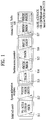
- FIG. 1 illustrates physical channels and a general method using the physical channels, which may be used in embodiments of the present invention.
- the UE When a UE is powered on or enters a new cell, the UE performs initial cell search (S11).
- the initial cell search involves acquisition of synchronization to an eNB. Specifically, the UE synchronizes its timing to the eNB and acquires information such as a cell Identifier (ID) by receiving a Primary Synchronization Channel (P-SCH) and a Secondary Synchronization Channel (S-SCH) from the eNB.
- ID cell Identifier
- P-SCH Primary Synchronization Channel
- S-SCH Secondary Synchronization Channel
- the UE may acquire information broadcast in the cell by receiving a Physical Broadcast Channel (PBCH) from the eNB.
- PBCH Physical Broadcast Channel
- the UE may monitor a DL channel state by receiving a Downlink Reference Signal (DL RS).
- DL RS Downlink Reference Signal
- the UE may acquire more detailed system information by receiving a Physical Downlink Control Channel (PDCCH) and receiving a Physical Downlink Shared Channel (PDSCH) based on information of the PDCCH (S12).
- PDCCH Physical Downlink Control Channel
- PDSCH Physical Downlink Shared Channel
- the UE may perform a random access procedure with the eNB (S13 to S16).
- the UE may transmit a preamble on a Physical Random Access Channel (PRACH) (S13) and may receive a PDCCH and a PDSCH associated with the PDCCH (S14).
- PRACH Physical Random Access Channel
- the UE may additionally perform a contention resolution procedure including transmission of an additional PRACH (S15) and reception of a PDCCH signal and a PDSCH signal corresponding to the PDCCH signal (S16).
- the UE may receive a PDCCH and/or a PDSCH from the eNB (S17) and transmit a Physical Uplink Shared Channel (PUSCH) and/or a Physical Uplink Control Channel (PUCCH) to the eNB (S18), in a general UL/DL signal transmission procedure.
- PUSCH Physical Uplink Shared Channel
- PUCCH Physical Uplink Control Channel
- the UCI includes a Hybrid Automatic Repeat and reQuest Acknowledgement/Negative Acknowledgement (HARQ-ACK/NACK), a Scheduling Request (SR), a Channel Quality Indicator (CQI), a Precoding Matrix Index (PMI), a Rank Indicator (RI), etc.
- HARQ-ACK/NACK Hybrid Automatic Repeat and reQuest Acknowledgement/Negative Acknowledgement
- SR Scheduling Request
- CQI Channel Quality Indicator
- PMI Precoding Matrix Index
- RI Rank Indicator
- UCI is generally transmitted on a PUCCH periodically. However, if control information and traffic data should be transmitted simultaneously, the control information and traffic data may be transmitted on a PUSCH. In addition, the UCI may be transmitted aperiodically on the PUSCH, upon receipt of a request/command from a network.
- FIG. 2 illustrates exemplary radio frame structures used in embodiments of the present invention.
- FIG. 2(a) illustrates frame structure type 1.
- Frame structure type 1 is applicable to both a full Frequency Division Duplex (FDD) system and a half FDD system.
- FDD Frequency Division Duplex
- One subframe includes two successive slots.
- An i th subframe includes 2i th and (2i+1) th slots. That is, a radio frame includes 10 subframes.
- a time required for transmitting one subframe is defined as a Transmission Time Interval (TTI).
- One slot includes a plurality of Orthogonal Frequency Division Multiplexing (OFDM) symbols or SC-FDMA symbols in the time domain by a plurality of Resource Blocks (RBs) in the frequency domain.
- OFDM Orthogonal Frequency Division Multiplexing
- RBs Resource Blocks
- a slot includes a plurality of OFDM symbols in the time domain. Since OFDMA is adopted for DL in the 3GPP LTE system, one OFDM symbol represents one symbol period. An OFDM symbol may be called an SC-FDMA symbol or symbol period. An RB is a resource allocation unit including a plurality of contiguous subcarriers in one slot.
- each of 10 subframes may be used simultaneously for DL transmission and UL transmission during a 10-ms duration.
- the DL transmission and the UL transmission are distinguished by frequency.
- a UE cannot perform transmission and reception simultaneously in a half FDD system.
- the above radio frame structure is purely exemplary.
- the number of subframes in a radio frame, the number of slots in a subframe, and the number of OFDM symbols in a slot may be changed.
- FIG. 2(b) illustrates frame structure type 2.
- Frame structure type 2 is applied to a Time Division Duplex (TDD) system.
- TDD Time Division Duplex
- a type-2 frame includes a special subframe having three fields, Downlink Pilot Time Slot (DwPTS), Guard Period (GP), and Uplink Pilot Time Slot (UpPTS).
- DwPTS Downlink Pilot Time Slot
- GP Guard Period
- UpPTS Uplink Pilot Time Slot
- the DwPTS is used for initial cell search, synchronization, or channel estimation at a UE
- the UpPTS is used for channel estimation and UL transmission synchronization with a UE at an eNB.
- the GP is used to cancel UL interference between a UL and a DL, caused by the multi-path delay of a DL signal.
- FIG. 3 illustrates an exemplary structure of a DL resource grid for the duration of one DL slot, which may be used in embodiments of the present invention.
- a DL slot includes a plurality of OFDM symbols in the time domain.
- One DL slot includes 7 OFDM symbols in the time domain and an RB includes 12 subcarriers in the frequency domain, to which the present invention is not limited.
- Each element of the resource grid is referred to as a Resource Element (RE).
- An RB includes 12x7 REs.
- the number of RBs in a DL slot, NDL depends on a DL transmission bandwidth.
- a UL slot may have the same structure as a DL slot.
- FIG. 4 illustrates a structure of a UL subframe which may be used in embodiments of the present invention.
- a UL subframe may be divided into a control region and a data region in the frequency domain.
- a PUCCH carrying UCI is allocated to the control region and a PUSCH carrying user data is allocated to the data region.
- a UE does not transmit a PUCCH and a PUSCH simultaneously.
- a pair of RBs in a subframe are allocated to a PUCCH for a UE.
- the RBs of the RB pair occupy different subcarriers in two slots. Thus it is said that the RB pair frequency-hops over a slot boundary.
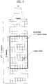
- FIG. 5 illustrates a structure of a DL subframe that may be used in embodiments of the present invention.
- DL control channels defined for the 3GPP LTE system include a Physical Control Format Indicator Channel (PCFICH), a PDCCH, and a Physical Hybrid ARQ Indicator Channel (PHICH).
- PCFICH Physical Control Format Indicator Channel
- PDCCH Physical Downlink Control Channel
- PHICH Physical Hybrid ARQ Indicator Channel
- the PCFICH is transmitted in the first OFDM symbol of a subframe, carrying information about the number of OFDM symbols used for transmission of control channels (i.e. the size of the control region) in the subframe.
- the PHICH is a response channel to a UL transmission, delivering an HARQ ACK/NACK signal.
- Control information carried on the PDCCH is called Downlink Control Information (DCI).
- the DCI transports UL resource assignment information, DL resource assignment information, or UL Transmission (Tx) power control commands for a UE group.
- CA Carrier Aggregation
- a 3GPP LTE system (conforming to Rel-8 or Rel-9) (hereinafter, referred to as an LTE system) uses Multi-Carrier Modulation (MCM) in which a single Component Carrier (CC) is divided into a plurality of bands.
- MCM Multi-Carrier Modulation
- a 3GPP LTE-A system (hereinafter, referred to an LTE-A system) may use CA by aggregating one or more CCs to support a broader system bandwidth than the LTE system.
- CA is interchangeably used with carrier combining, multi-CC environment, or multi-carrier environment.
- multi-carrier means CA (or carrier combining).
- CA covers aggregation of contiguous carriers and aggregation of non-contiguous carriers.
- the number of aggregated CCs may be different for a DL and a UL. If the number of DL CCs is equal to the number of UL CCs, this is called symmetric aggregation. If the number of DL CCs is different from the number of UL CCs, this is called asymmetric aggregation.
- CA is interchangeable with carrier combining, bandwidth aggregation, spectrum aggregation, etc.
- the LTE-A system aims to support a bandwidth of up to 100MHz by aggregating two or more CCs, that is, by CA.
- each of one or more carriers which has a smaller bandwidth than a target bandwidth, may be limited to a bandwidth used in the legacy system.
- the legacy 3GPP LTE system supports bandwidths ⁇ 1.4, 3, 5, 10, 15, and 20MHz ⁇ and the 3GPP LTE-A system may support a broader bandwidth than 20MHz using these LTE bandwidths.
- a CA system of the present invention may support CA by defining a new bandwidth irrespective of the bandwidths used in the legacy system.
- Intra-band CA means that a plurality of DL CCs and/or UL CCs are successive or adjacent in frequency. In other words, the carrier frequencies of the DL CCs and/or UL CCs are positioned in the same band.
- inter-band CA an environment where CCs are far away from each other in frequency
- the carrier frequencies of a plurality of DL CCs and/or UL CCs are positioned in different bands.
- a UE may use a plurality of Radio Frequency (RF) ends to conduct communication in a CA environment.
- RF Radio Frequency
- the LTE-A system adopts the concept of cell to manage radio resources.
- the above-described CA environment may be referred to as a multi-cell environment.
- a cell is defined as a pair of DL and UL CCs, although the UL resources are not mandatory. Accordingly, a cell may be configured with DL resources alone or DL and UL resources.
- the UE may have one DL CC and one UL CC. If two or more serving cells are configured for the UE, the UE may have as many DL CCs as the number of the serving cells and as many UL CCs as or fewer UL CCs than the number of the serving cells, or vice versa. That is, if a plurality of serving cells are configured for the UE, a CA environment using more UL CCs than DL CCs may also be supported.
- CA may be regarded as aggregation of two or more cells having different carrier frequencies (center frequencies).
- center frequencies center frequencies
- 'cell' should be distinguished from 'cell' as a geographical area covered by an eNB.
- intra-band CA is referred to as intra-band multi-cell and inter-band CA is referred to as inter-band multi-cell.
- a Primacy Cell (PCell) and a Secondary Cell (SCell) are defined.
- a PCell and an SCell may be used as serving cells.
- a single serving cell including only a PCell exists for the UE.
- the UE is in RRC_CONNECTED state and CA is configured for the UE, one or more serving cells may exist for the UE, including a PCell and one or more SCells.
- Serving cells may be configured by an RRC parameter.
- a physical-layer ID of a cell PhysCellId is an integer value ranging from 0 to 503.
- a short ID of an SCell SCellIndex is an integer value ranging from 1 to 7.
- a short ID of a serving cell PCell or SCell
- ServeCellIndex is an integer value ranging from 1 to 7. If ServeCellIndex is 0, this indicates a PCell and the values of ServeCellIndex for SCells are pre-assigned. That is, the smallest cell ID (or cell index) of ServeCellIndex indicates a PCell.
- a PCell refers to a cell operating in a primary frequency (or a primary CC).
- a UE may use a PCell for initial connection establishment or connection reestablishment.
- the PCell may be a cell indicated during handover.
- the PCell is a cell responsible for control-related communication among serving cells configured in a CA environment. That is, PUCCH allocation and transmission for the UE may take place only in the PCell.
- the UE may use only the PCell in acquiring system information or changing a monitoring procedure.
- An Evolved Universal Terrestrial Radio Access Network (E-UTRAN) may change only a PCell for a handover procedure by a higher-layer RRCConnectionReconfiguraiton message including mobilityControlInfo to a UE supporting CA.
- E-UTRAN Evolved Universal Terrestrial Radio Access Network
- An SCell may refer to a cell operating in a secondary frequency (or a secondary CC). Although only one PCell is allocated to a specific UE, one or more SCells may be allocated to the UE. An SCell may be configured after RRC connection establishment and may be used to provide additional radio resources. There is no PUCCH in cells other than a PCell, that is, in SCells among serving cells configured in the CA environment.
- the E-UTRAN may transmit all system information related to operations of related cells in RRC_CONNECTED state to the UE by dedicated signaling. Changing system information may be controlled by releasing and adding a related SCell.
- a higher-layer RRCConnectionReconfiguration message may be used.
- the E-UTRAN may transmit a dedicated signal having a different parameter for each cell rather than it broadcasts in a related SCell.
- the E-UTRAN may configure a network including one or more SCells by adding the SCells to a PCell initially configured during a connection establishment procedure.
- each of a PCell and an SCell may operate as a CC.
- a Primary CC (PCC) and a PCell may be used in the same meaning and a Secondary CC (SCC) and an SCell may be used in the same meaning in embodiments of the present invention.
- Cross carrier scheduling may be called cross CC scheduling or cross cell scheduling.
- a PDCCH (carrying a DL grant) and a PDSCH are transmitted in the same DL CC or a PUSCH is transmitted in a UL CC linked to a DL CC in which a PDCCH (carrying a UL grant) is received.
- a PDCCH (carrying a DL grant) and a PDSCH are transmitted in different DL CCs or a PUSCH is transmitted in a UL CC other than a UL CC linked to a DL CC in which a PDCCH (carrying a UL grant) is received.
- Cross carrier scheduling may be activated or deactivated UE-specifically and indicated to each UE semi-statically by higher-layer signaling (e.g. RRC signaling).
- higher-layer signaling e.g. RRC signaling
- a Carrier Indicator Field is required in a PDCCH to indicate a DL/UL CC in which a PDSCH/PUSCH indicated by the PDCCH is to be transmitted.
- the PDCCH may allocate PDSCH resources or PUSCH resources to one of a plurality of CCs by the CIF. That is, when a PDCCH of a DL CC allocates PDSCH or PUSCH resources to one of aggregated DL/UL CCs, a CIF is set in the PDCCH.
- the DCI formats of LTE Release-8 may be extended according to the CIF.
- the CIF may be fixed to three bits and the position of the CIF may be fixed irrespective of a DCI format size.
- the LTE Release-8 PDCCH structure (the same coding and resource mapping based on the same CCEs) may be reused.
- a PDCCH transmitted in a DL CC allocates PDSCH resources of the same DL CC or allocates PUSCH resources in a single UL CC linked to the DL CC, a CIF is not set in the PDCCH.
- the LTE Release-8 PDCCH structure (the same coding and resource mapping based on the same CCEs) may be used.
- a UE needs to monitor a plurality of PDCCHs for DCI in the control region of a monitoring CC according to the transmission mode and/or bandwidth of each CC. Accordingly, an appropriate SS configuration and PDCCH monitoring are needed for the purpose.
- a UE DL CC set is a set of DL CCs scheduled for a UE to receive a PDSCH
- a UE UL CC set is a set of UL CCs scheduled for a UE to transmit a PUSCH.
- a PDCCH monitoring set is a set of one or more DL CCs in which a PDCCH is monitored.
- the PDCCH monitoring set may be identical to the UE DL CC set or may be a subset of the UE DL CC set.
- the PDCCH monitoring set may include at least one of the DL CCs of the UE DL CC set. Or the PDCCH monitoring set may be defined irrespective of the UE DL CC set.
- the DL CCs included in the PDCCH monitoring set may be configured to always enable self-scheduling for UL CCs linked to the DL CCs.
- the UE DL CC set, the UE UL CC set, and the PDCCH monitoring set may be configured UE-specifically, UE group-specifically, or cell-specifically.
- the PDCCH monitoring set is always identical to the UE DL CC set. In this case, there is no need for signaling the PDCCH monitoring set.
- the PDCCH monitoring set is preferably defined within the UE DL CC set. That is, the eNB transmits a PDCCH only in the PDCCH monitoring set to schedule a PDSCH or PUSCH for the UE.
- FIG. 6 illustrates a cross carrier-scheduled subframe structure in the LTE-A system, which is used in embodiments of the present invention.
- DL CC 'A' is configured as a PDCCH monitoring DL CC. If a CIF is not used, each DL CC may deliver a PDCCH that schedules a PDSCH in the same DL CC without a CIF. On the other hand, if the CIF is used by higher-layer signaling, only DL CC 'A' may carry a PDCCH that schedules a PDSCH in the same DL CC 'A' or another CC. Herein, no PDCCH is transmitted in DL CC 'B' and DL CC 'C' that are not configured as PDCCH monitoring DL CCs.
- cell coverage of a small cell is very smaller (for example, several m radiuses to several tens of m radiuses) than cell coverage of a macro cell.
- a shading effect that reaches a user equipment (UE) through buildings may rapidly be changed depending on a location of the UE, or a line of sight (LOS)/non-LOS environment may easily be changed.
- UE user equipment
- LOS line of sight
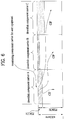
- FIG. 7 illustrates an example of a case where SNRs between UEs are different from each other when a base station performs beamforming.
- the base station transmits a signal towards UE1 and UE2 by performing beamforming
- the UE1 can assure LOS to acquire a signal of good quality
- the UE2 cannot assure LOS due to buildings and receives a signal of poor quality due to a non-LOS environment.
- the embodiments of the present invention relate to efficient data symbol transmission and reception methods robust to a rapid change of a channel status, for supporting multiple users.
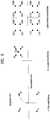
- FIG. 8 illustrates an example of a hierarchical modulation method.
- FIG. 8 An example of a hierarchical modulation (HM) method will be described with reference to FIG. 8 .
- data bits are configured as a constellation of quadrature amplitude modulation (QAM).
- FIG. 8(a) illustrates that data bits are configured in quadrature phase shift keying (QPSK) or 4 QAM.
- QPSK quadrature phase shift keying
- a constellation of a higher order may be used, or data bits may be configured using differential M-PSK or another modulation method.
- a distance from a starting point to each symbol is defined as 'r'.
- FIG. 8(b) illustrates that data bits are configured in QPSK or 4 QAM based on a reference point of a first quadrant of FIG. 8(a) .
- a distance from the reference point to a point of FIG. 8(b) is defined as 'd'.
- FIG. 8(c) illustrates a constellation finally constituting hierarchical modulation (HM).
- the constellation of FIG. 8(c) is configured similarly to a constellation of 16 QAM.
- the HM method is advantageous in that robustness of an error of the least significant bit (LSB) and the most significant bit (MSB), which constitute one symbol, can be configured differentially.
- the constellation of FIG. 8(a) is comprised of 4 points and thus can be expressed by 2 bits. At this time, each point is defined as 'S' symbol.
- the constellation of FIG. 8(b) is also comprised of 4 points and thus can be expressed by 2 bits. At this time, each point is defined as 'a' symbol. Therefore, one point of FIG. 8(c) can finally be expressed by 4 bits as shown in FIG. 9.
- FIG. 9 illustrates an example of bit configuration of HM symbols. In FIG. 9 , X means each bit.
- the constellation may be configured such that the distance of 'r' may be greater than the distance of 'd'. Therefore, the bits constituting the 'S' symbols are robuster to an error than the bits constituting the 'a' symbols. This is because that a Euclidian distance of the 'S' symbols is greater than that of the 'a' symbols. If the constellation is configured such that the distance of 'r' is smaller than the distance of 'd', robustness of the bits constituting the 'a' symbols will be greater than that of the bits constituting the 'S' symbols.
- each symbol configuration method and/or transmission scheme is varied during configuration of HM, whereby data symbols can be transmitted and received with robustness in various channel statuses.
- the 'S' symbol may be defined as a first symbol or first sub-symbol, and the 'a' symbol may be defined as a second symbol or second sub-symbol.
- FIG. 10 illustrates methods for configuring S symbols.
- FIG. 10(a) illustrates that S symbols to be transmitted to two transmitting antennas are generated when the number of streams or codewords to be forwarded to a first user equipment (UE1).
- the S symbols which will be transmitted from each transmitting antenna may be configured using a spatial multiplexing (SM) scheme.
- the transmitting antenna may configure the S symbols by using different types of information bits, wherein the generated S symbols may be mapped into one point of constellations the same as or different from each other.
- SM spatial multiplexing
- FIG. 10(a) illustrates that the number of codewords is 2, the number of codewords may be 1 or 3. However, data bits constituting each S symbol should be different from each other.
- FIG. 10(b) illustrates that beamforming is used by performing precoding for S symbols which will be transmitted from each antenna. For example, if rank of a channel is 1, the number of codewords is 1 and precoding is available, precoding may be performed for the S symbols generated for multi-antenna transmission.
- an identity matrix may be included in a precoding matrix used for precoding, and a precoding matrix, which can maximize a receiving SNR, may be selected within a codebook.
- the S symbols may be configured from a codeword 1, and the configured S symbols may be input to a precoder and mapped into each transmitting antenna.
- FIG. 10(c) illustrates that space time coding is applied to S symbols which will be transmitted. For example, if the number of antennas is 2 or more, space time coding may be applied to the generated S symbols. Alamouti coding such as S 1 ⁇ S 2 * S 2 S 1 * may be used as space time coding when the number of antennas is 2.
- FIG. 10(c) illustrates that coding is performed based on space time block coding (STBC)
- coding may be performed using space and frequency region such as space frequency block coding (SFBC).
- SFBC space frequency block coding
- a transmitter may transmit the S symbols by coding for the S symbols using various SFBC/STBC schemes when the number of antennas is 3 or more.
- the methods for configuring 'S' symbols in the above section 3.2 may equally be applied to configuration of 'a' symbols. That is, the 'a' symbols may be configured using (1) SM scheme, (2) precoding scheme or (3) space time coding scheme.
- Final HM symbols may be generated using the 'S' symbols and the 'a' symbols configured through the above sections 3.2 and 3.3.
- the HM symbols may be generated by adding the 'a' symbols based on the 'S' symbols.
- power scaling for allowing the 'S' symbol and the 'a' symbol to be spaced apart from each other as much as the distance r or d is not performed for the 'S' symbol and the 'a' symbol. Therefore, power scaling may be performed before final symbols are generated, whereby error sensitivity of each symbol may be set differently.
- FIG. 11 illustrates one of methods for configuring final HM symbols.
- the transmitter configures 'S' symbols and 'a' symbols, respectively.
- the 'S' symbols and the 'a' symbols may be generated based on the aforementioned methods for configuring symbols.
- power scaling is performed for the 'S' symbol to have a longer Euclidian distance 'r'
- ad power scaling is performed for the 'a' symbol to have a shorter Euclidian distance 'd' (r>d).
- the 'S' symbols and the 'a' symbols subjected to power scaling may be combined with each other to configure final HM symbols.
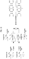
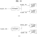
- FIGS. 12 and 13 illustrate methods for configuring information bits constituting 'a' symbols and 'S' symbols.
- the HM method may be used to transmit common information such as a broadcast channel and a common control channel. That is, same information bits such as broadcast information and common control channel information may be used as information bits of the 'S' symbols and the 'a' symbols (refer to FIG. 12(a) ).
- the information bits for configuring the 'a' symbols may be those for the same user as that for the 'S' symbols, the information bits may be configured as those for another user different from that for the 'S' symbols (refer to FIG. 12(c) ).
- the transmitter may configure the 'S' and 'a' symbols by repeating the same information bits (refer to FIG. 13(a) ), or may configure the 'S' and 'a' symbols by multiplexing the 'S' symbols and the 'a' symbols (refer to FIG. 13(b) ).
- the transmitter may transmit the HM symbols configured by combination of the aforementioned methods.
- the transmitter may transmit the 'S' symbols by using beamforming and generate the 'a' symbols by using space time coding.
- the UE may acquire information with robustness in a LOS/non-LOS environment.
- the transmitter can acquire information at a high SNR, and can acquire information at a high SNR by obtaining diversity through the 'a' symbols in the non-LOS environment.
- a receiver may acquire additional SNR gain through MRC scheme of information obtained using the 'S' symbols and information obtained using the 'a' symbols.
- the transmitter may perform single data transmission of the 'S' symbols by using a first codeword (codeword 1) (for example, a case where precoding is performed using an identity matrix), and may perform beamforming for a final constellation of the 'a' symbols, which is formed using space time coding.
- codeword 1 for example, a case where precoding is performed using an identity matrix
- the number of antennas of a transmitter for example, base station
- the number of antennas of a receiver for example, UE
- space time coding for example, STBC
- W 2 h 2 * ⁇ h 2 ⁇ 2
- W 1 means a precoding matrix for a first antenna
- W 2 means a precoding matrix for a second antenna
- h 1 means a channel during transmission through the first antenna
- h 2 means a channel during transmission through a second antenna.
- the receiver performs symbol detection by using a slicing function Q.
- the slicing function means a function that performs simple mapping of receiving symbols into the nearest constellation point by using one of hard decision methods.
- Equation 1 may be arranged as expressed by the following Equation 2.
- the receiver can identify a quadrant of a constellation, from which the 'S' symbols are detected by applying the slicing function Q to the Equation 2.
- the receiver can derive the following Equation 3 based on the Equations 1 and 2.
- the value of p derived from the Equation 3 is a value used to detect the 'a' symbols later.
- Equation 4 may be arranged as expressed by the following Equation 5.
- the receiver may derive the following Equation 6 based on the Equations 4 and 5.
- the value of q derived from the Equation 6 is a value used to detect the 'a' symbols later.
- the receiver can determine the 'S' symbols through the HM symbols transmitted by beamforming. That is, the receiver detects the 'S' symbols by using the slicing function Q. Afterwards, the receiver can detect the 'a' symbols by using addition and subtraction of the signals received for the first and second time intervals.
- Equation 7 expresses one of methods by which the UE detects the 'a' symbols.
- the receiver can detect the 'S' symbols and the 'a' symbols through the Equations 1 to 7.
- FIG. 14 briefly illustrates a method for transmitting and receiving HM symbols.
- the transmitter may select control or data bits for configuring the HM symbols. Also, the transmitter may select a target for transmitting the HM symbols. Although this process is now shown in FIG. 14 , it is preferable that this process is performed before the 'S' symbols are configured. Details of this process will be understood with reference to the section 3.5.
- the transmitter configures the 'S' symbols as described in the section 3.2, and configures the 'a' symbols as described in the section 3.3 (S1410, S1430).
- the transmitter configures the HM symbols by means of combination of the 'S' symbols and the 'a' symbols. At this time, the transmitter performs power scaling for the 'S' symbols and the 'a' symbols.
- the details of power scaling will be understood with reference to the section 3.4.
- (1) SM method, (2) beamforming method and (3) space time coding e.g., STBC, SFBC, etc.
- (1) SM method, (2) beamforming method and (3) space time coding e.g., STBC, SFBC, etc.
- space time coding e.g., STBC, SFBC, etc.
- the transmitter transmits the configured HM symbols to the receiver (S 1470).
- the transmitter does not need to notify the receiver of information as to how the HM symbols have been configured.
- the transmitter in the case that the HM symbols are configured dynamically or semi-statically, it is preferable that the transmitter previously notifies the receiver of the configuration method of the HM symbols.
- the receiver receives the HM symbols (S1420).
- the receiver detects each of the 'S' symbols and the 'a' symbols from the HM symbols. For example, in the section 3.6, the receiver has transmitted and detected the 'S' symbols based on beamforming, and has transmitted and detected the 'a' symbols based on space time coding (S1440, S1460).
- the transmitter may transmit the 'S' symbols in accordance with space time coding and transmit the 'a' symbols in accordance with beamforming, and vice versa.
- the 'S' symbols and the 'a' symbols may be transmitted and received by various combinations of the methods described in the sections 3.2 and 3.3.
- system information or control information may be transmitted for transmission of the 'S' symbols, and normal data may be transmitted for transmission of the 'a' symbols.
- same control information or same data may be transmitted for transmission of the 'S' and 'a' symbols.
- robust data transmission can be performed in an environment where a channel status is changed rapidly.
- Apparatuses illustrated in FIG. 15 are means that can implement the methods described before with reference to FIGS. 1 to 14 .
- a UE may act as a transmission end on UL and as a reception end on DL.
- An eNB may act as a reception end on UL and as a transmission end on DL.
- each of the UE and the eNB may include a transmitter (Tx) 1540 or 1550, and a receiver (Rx) 1550 or 1570, for controlling transmission and reception of information, data, and/or messages, and an antenna 1500 or 1510 for transmitting and receiving information, data, and/or messages.
- Tx transmitter
- Rx receiver
- FIG. 15 illustrates that the number of antennas is 3, this is intended to illustrate a plurality of antennas, and two or more antennas may be provided in the UE or the eNB.
- Each of the UE and the eNB may further include a processor 1520 or 1530 for implementing the afore-described embodiments of the present invention and a memory 1580 or 1590 for temporarily or permanently storing operations of the processor 1520 or 1530.
- the embodiments of the present invention can be performed using the aforementioned components and functions of the UE and the eNB.
- the processor of the UE or the eNB may configure 'S' symbols and 'a' symbols for configuring HM symbols, respectively, and may configure the HM symbols by means of combination of the 'S' and 'a' symbols.
- the processor of the eNB and the UE may transmit and/or receive the HM symbols by controlling the transmitter and the receiver.
- the embodiments of the present invention may be operated in the LTE/LTE-A system described in the sections 1 and 2, and may be applied to even a carrier aggregation environment.
- the Transmitter and the Receiver of the UE and the eNB may perform a pac ket modulation/demodulation function for data transmission, a high-speed packet channel c oding function, OFDMA packet scheduling, TDD packet scheduling, and/or channelization.
- Each of the UE and the eNB of FIG. 15 may further include a low-power Radio Frequency (RF)/Intermediate Frequency (IF) module.
- RF Radio Frequency
- IF Intermediate Frequency
- the Transmitter and the Receiver may be called a transmitter and a receiver, respectively. If the Transmitter and the Receiver are used together, they may be called a transceiver.
- the UE may be any of a Personal Digital Assistant (PDA), a cellular phone, a Personal Communication Service (PCS) phone, a Global System for Mobile (GSM) phone, a Wideband Code Division Multiple Access (WCDMA) phone, a Mobile Broadband System (MBS) phone, a hand-held PC, a laptop PC, a smart phone, a Multi Mode-Multi Band (MM-MB) terminal, etc.
- PDA Personal Digital Assistant
- PCS Personal Communication Service
- GSM Global System for Mobile
- WCDMA Wideband Code Division Multiple Access
- MBS Mobile Broadband System
- hand-held PC a laptop PC
- smart phone a Multi Mode-Multi Band (MM-MB) terminal, etc.
- MM-MB Multi Mode-Multi Band
- the smart phone is a terminal taking the advantages of both a mobile phone and a PDA. It incorporates the functions of a PDA, that is, scheduling and data communications such as fax transmission and reception and Internet connection into a mobile phone.
- the MB-MM terminal refers to a terminal which has a multi-modem chip built therein and which can operate in any of a mobile Internet system and other mobile communication systems (e.g. CDMA 2000, WCDMA, etc.).
- Embodiments of the present invention may be achieved by various means, for example, hardware, firmware, software, or a combination thereof.
- the methods according to exemplary embodiments of the present invention may be achieved by one or more Application Specific Integrated Circuits (ASICs), Digital Signal Processors (DSPs), Digital Signal Processing Devices (DSPDs), Programmable Logic Devices (PLDs), Field Programmable Gate Arrays (FPGAs), processors, controllers, microcontrollers, microprocessors, etc.
- ASICs Application Specific Integrated Circuits
- DSPs Digital Signal Processors
- DSPDs Digital Signal Processing Devices
- PLDs Programmable Logic Devices
- FPGAs Field Programmable Gate Arrays
- processors controllers, microcontrollers, microprocessors, etc.
- the methods according to the embodiments of the present invention may be implemented in the form of a module, a procedure, a function, etc. performing the above-described functions or operations.
- a software code may be stored in the memory 1580 or 1590 and executed by the processor 1540 or 1530.
- the memory is located at the interior or exterior of the processor and may transmit and receive data to and from the processor via various known means.
- Embodiments of the present invention are applicable to various wireless access systems including a 3GPP system, a 3GPP2 system, and/or an IEEE 802.xx system. In addition to these wireless access systems, the embodiments of the present invention are applicable to all technical fields in which the wireless access systems find their applications.
Landscapes
- Engineering & Computer Science (AREA)
- Computer Networks & Wireless Communication (AREA)
- Signal Processing (AREA)
- Mobile Radio Communication Systems (AREA)
Applications Claiming Priority (2)
| Application Number | Priority Date | Filing Date | Title |
|---|---|---|---|
| US201361856037P | 2013-07-18 | 2013-07-18 | |
| PCT/KR2014/006537 WO2015009101A1 (ko) | 2013-07-18 | 2014-07-18 | 무선 접속 시스템에서 계층적 변조를 이용한 강건한 심볼 송수신 방법 |
Publications (3)
| Publication Number | Publication Date |
|---|---|
| EP3024190A1 EP3024190A1 (en) | 2016-05-25 |
| EP3024190A4 EP3024190A4 (en) | 2017-03-01 |
| EP3024190B1 true EP3024190B1 (en) | 2019-05-01 |
Family
ID=52346472
Family Applications (1)
| Application Number | Title | Priority Date | Filing Date |
|---|---|---|---|
| EP14826055.7A Not-in-force EP3024190B1 (en) | 2013-07-18 | 2014-07-18 | Robust symbol transmission and reception method using hierarchical modulation in wireless access system |
Country Status (3)
| Country | Link |
|---|---|
| US (1) | US9660766B2 (ko) |
| EP (1) | EP3024190B1 (ko) |
| WO (1) | WO2015009101A1 (ko) |
Families Citing this family (3)
| Publication number | Priority date | Publication date | Assignee | Title |
|---|---|---|---|---|
| US10171989B2 (en) | 2015-09-17 | 2019-01-01 | Telefonaktiebolaget Lm Ericsson (Publ) | Transmitting user data to a wireless communication device over a control channel |
| US10263671B2 (en) * | 2015-12-31 | 2019-04-16 | Lg Electronics Inc. | Method for reporting reference signal indicator to base station by terminal in wireless communication system and apparatus therefor |
| EP3479515B1 (en) * | 2016-09-30 | 2020-06-03 | Motorola Mobility LLC | Flexible radio resource allocation |
Family Cites Families (10)
| Publication number | Priority date | Publication date | Assignee | Title |
|---|---|---|---|---|
| US7724838B2 (en) * | 2003-09-25 | 2010-05-25 | Qualcomm Incorporated | Hierarchical coding with multiple antennas in a wireless communication system |
| US8059608B2 (en) | 2005-06-14 | 2011-11-15 | Qualcomm Incorporated | Transmit spatial diversity for cellular single frequency networks |
| TW200738020A (en) | 2006-02-01 | 2007-10-01 | Lg Electronics Inc | A method of transmitting and receiving data using superpostion modulation in a wireless communication system |
| JP4852144B2 (ja) * | 2006-05-17 | 2012-01-11 | エルジー エレクトロニクス インコーポレイティド | 無線通信システムで順方向リンクのための重畳コーディングを具現する方法 |
| US8116412B1 (en) | 2006-12-30 | 2012-02-14 | Rockstar Bidco, LP | Modulation division multiple access |
| US8005160B2 (en) | 2006-12-30 | 2011-08-23 | Nortel Networks Limited | Processing differentiated hierarchical modulation used in radio frequency communications |
| CN101682497B (zh) | 2007-06-08 | 2013-06-05 | 高通股份有限公司 | 单载波频分多址中对通信信道的分层调制 |
| US8284693B2 (en) | 2009-02-03 | 2012-10-09 | Broadcom Corporation | Multi-stream priority-based space-time coding |
| JP5494809B2 (ja) * | 2009-10-09 | 2014-05-21 | 富士通株式会社 | 基地局、マルチアンテナ通信システム及びその通信方法 |
| US20120076204A1 (en) * | 2010-09-23 | 2012-03-29 | Qualcomm Incorporated | Method and apparatus for scalable multimedia broadcast using a multi-carrier communication system |
-
2014
- 2014-07-18 WO PCT/KR2014/006537 patent/WO2015009101A1/ko active Application Filing
- 2014-07-18 EP EP14826055.7A patent/EP3024190B1/en not_active Not-in-force
- 2014-07-18 US US14/905,247 patent/US9660766B2/en active Active
Non-Patent Citations (1)
| Title |
|---|
| None * |
Also Published As
| Publication number | Publication date |
|---|---|
| US20160149670A1 (en) | 2016-05-26 |
| EP3024190A1 (en) | 2016-05-25 |
| US9660766B2 (en) | 2017-05-23 |
| EP3024190A4 (en) | 2017-03-01 |
| WO2015009101A1 (ko) | 2015-01-22 |
Similar Documents
| Publication | Publication Date | Title |
|---|---|---|
| KR101978852B1 (ko) | 무선 통신 시스템에서 참조 신호를 송수신하기 위한 방법 및 이를 위한 장치 | |
| JP6431587B2 (ja) | 機械タイプ通信を支援する無線接続システムにおいてチャネル状態情報送信方法及び装置 | |
| EP3041154B1 (en) | Method and device for transmitting channel state information in wireless access system supporting machine type communication | |
| KR101830745B1 (ko) | 기계타입통신을 지원하는 무선 접속 시스템에서 상향링크 전송 전력을 제어하는 방법 및 장치 | |
| US9794043B2 (en) | Method and device for transmitting channel status information in wireless access system | |
| KR101842204B1 (ko) | 무선접속 시스템에서 256qam 지원을 위한 채널상태정보 보고 방법 및 장치 | |
| US9794046B2 (en) | Method for transmitting uplink control information in wireless access system and apparatus therefor | |
| JP6370808B2 (ja) | 無線接続システムにおいて擬似コロケーションを行う方法および装置 | |
| EP2731284B1 (en) | Method for transceiving a reference signal in a wireless connection system and terminal therefor | |
| EP2988557B1 (en) | Power control method and apparatus in wireless access system | |
| EP3206324B1 (en) | Reference signal generation method in wireless communication system supporting massive mimo | |
| US9935751B2 (en) | Methods and devices for transmitting sounding reference signal in wireless access system | |
| US20160211904A1 (en) | Method and device for transmitting and receiving channel state information for supporting 256 qam in wireless access system | |
| EP3094023B1 (en) | Method and apparatus for constructing frame structure in wireless access system supporting fdr transmission | |
| US9860886B2 (en) | Methods and devices for transceiving/transmitting downlink data in wireless access system supporting new carrier type | |
| US9801164B2 (en) | Methods and devices for transmitting scheduling request in wireless access system | |
| WO2014189301A1 (ko) | 전 이중 무선 방식을 지원하는 무선 접속 시스템에서 적용되는 전 이중 무선 영역의 구조, 이를 할당하는 방법 및 장치 | |
| EP3024190B1 (en) | Robust symbol transmission and reception method using hierarchical modulation in wireless access system | |
| KR20160067096A (ko) | 전 이중 무선 방식을 지원하는 무선 접속 시스템에서 회전 프리코더 기반의 자기 간섭 제거 방법 및 장치 |
Legal Events
| Date | Code | Title | Description |
|---|---|---|---|
| PUAI | Public reference made under article 153(3) epc to a published international application that has entered the european phase |
Free format text: ORIGINAL CODE: 0009012 |
|
| 17P | Request for examination filed |
Effective date: 20160118 |
|
| AK | Designated contracting states |
Kind code of ref document: A1 Designated state(s): AL AT BE BG CH CY CZ DE DK EE ES FI FR GB GR HR HU IE IS IT LI LT LU LV MC MK MT NL NO PL PT RO RS SE SI SK SM TR |
|
| AX | Request for extension of the european patent |
Extension state: BA ME |
|
| DAX | Request for extension of the european patent (deleted) | ||
| A4 | Supplementary search report drawn up and despatched |
Effective date: 20170130 |
|
| RIC1 | Information provided on ipc code assigned before grant |
Ipc: H04L 27/34 20060101AFI20170124BHEP |
|
| STAA | Information on the status of an ep patent application or granted ep patent |
Free format text: STATUS: EXAMINATION IS IN PROGRESS |
|
| 17Q | First examination report despatched |
Effective date: 20180309 |
|
| GRAP | Despatch of communication of intention to grant a patent |
Free format text: ORIGINAL CODE: EPIDOSNIGR1 |
|
| STAA | Information on the status of an ep patent application or granted ep patent |
Free format text: STATUS: GRANT OF PATENT IS INTENDED |
|
| INTG | Intention to grant announced |
Effective date: 20181207 |
|
| GRAS | Grant fee paid |
Free format text: ORIGINAL CODE: EPIDOSNIGR3 |
|
| GRAA | (expected) grant |
Free format text: ORIGINAL CODE: 0009210 |
|
| STAA | Information on the status of an ep patent application or granted ep patent |
Free format text: STATUS: THE PATENT HAS BEEN GRANTED |
|
| AK | Designated contracting states |
Kind code of ref document: B1 Designated state(s): AL AT BE BG CH CY CZ DE DK EE ES FI FR GB GR HR HU IE IS IT LI LT LU LV MC MK MT NL NO PL PT RO RS SE SI SK SM TR |
|
| REG | Reference to a national code |
Ref country code: GB Ref legal event code: FG4D |
|
| REG | Reference to a national code |
Ref country code: CH Ref legal event code: EP Ref country code: AT Ref legal event code: REF Ref document number: 1128444 Country of ref document: AT Kind code of ref document: T Effective date: 20190515 |
|
| REG | Reference to a national code |
Ref country code: DE Ref legal event code: R096 Ref document number: 602014045933 Country of ref document: DE |
|
| REG | Reference to a national code |
Ref country code: IE Ref legal event code: FG4D |
|
| REG | Reference to a national code |
Ref country code: NL Ref legal event code: MP Effective date: 20190501 |
|
| REG | Reference to a national code |
Ref country code: LT Ref legal event code: MG4D |
|
| PG25 | Lapsed in a contracting state [announced via postgrant information from national office to epo] |
Ref country code: FI Free format text: LAPSE BECAUSE OF FAILURE TO SUBMIT A TRANSLATION OF THE DESCRIPTION OR TO PAY THE FEE WITHIN THE PRESCRIBED TIME-LIMIT Effective date: 20190501 Ref country code: AL Free format text: LAPSE BECAUSE OF FAILURE TO SUBMIT A TRANSLATION OF THE DESCRIPTION OR TO PAY THE FEE WITHIN THE PRESCRIBED TIME-LIMIT Effective date: 20190501 Ref country code: PT Free format text: LAPSE BECAUSE OF FAILURE TO SUBMIT A TRANSLATION OF THE DESCRIPTION OR TO PAY THE FEE WITHIN THE PRESCRIBED TIME-LIMIT Effective date: 20190901 Ref country code: HR Free format text: LAPSE BECAUSE OF FAILURE TO SUBMIT A TRANSLATION OF THE DESCRIPTION OR TO PAY THE FEE WITHIN THE PRESCRIBED TIME-LIMIT Effective date: 20190501 Ref country code: NO Free format text: LAPSE BECAUSE OF FAILURE TO SUBMIT A TRANSLATION OF THE DESCRIPTION OR TO PAY THE FEE WITHIN THE PRESCRIBED TIME-LIMIT Effective date: 20190801 Ref country code: NL Free format text: LAPSE BECAUSE OF FAILURE TO SUBMIT A TRANSLATION OF THE DESCRIPTION OR TO PAY THE FEE WITHIN THE PRESCRIBED TIME-LIMIT Effective date: 20190501 Ref country code: SE Free format text: LAPSE BECAUSE OF FAILURE TO SUBMIT A TRANSLATION OF THE DESCRIPTION OR TO PAY THE FEE WITHIN THE PRESCRIBED TIME-LIMIT Effective date: 20190501 Ref country code: ES Free format text: LAPSE BECAUSE OF FAILURE TO SUBMIT A TRANSLATION OF THE DESCRIPTION OR TO PAY THE FEE WITHIN THE PRESCRIBED TIME-LIMIT Effective date: 20190501 Ref country code: LT Free format text: LAPSE BECAUSE OF FAILURE TO SUBMIT A TRANSLATION OF THE DESCRIPTION OR TO PAY THE FEE WITHIN THE PRESCRIBED TIME-LIMIT Effective date: 20190501 |
|
| PG25 | Lapsed in a contracting state [announced via postgrant information from national office to epo] |
Ref country code: LV Free format text: LAPSE BECAUSE OF FAILURE TO SUBMIT A TRANSLATION OF THE DESCRIPTION OR TO PAY THE FEE WITHIN THE PRESCRIBED TIME-LIMIT Effective date: 20190501 Ref country code: BG Free format text: LAPSE BECAUSE OF FAILURE TO SUBMIT A TRANSLATION OF THE DESCRIPTION OR TO PAY THE FEE WITHIN THE PRESCRIBED TIME-LIMIT Effective date: 20190801 Ref country code: RS Free format text: LAPSE BECAUSE OF FAILURE TO SUBMIT A TRANSLATION OF THE DESCRIPTION OR TO PAY THE FEE WITHIN THE PRESCRIBED TIME-LIMIT Effective date: 20190501 Ref country code: GR Free format text: LAPSE BECAUSE OF FAILURE TO SUBMIT A TRANSLATION OF THE DESCRIPTION OR TO PAY THE FEE WITHIN THE PRESCRIBED TIME-LIMIT Effective date: 20190802 |
|
| REG | Reference to a national code |
Ref country code: AT Ref legal event code: MK05 Ref document number: 1128444 Country of ref document: AT Kind code of ref document: T Effective date: 20190501 |
|
| PG25 | Lapsed in a contracting state [announced via postgrant information from national office to epo] |
Ref country code: IS Free format text: LAPSE BECAUSE OF FAILURE TO SUBMIT A TRANSLATION OF THE DESCRIPTION OR TO PAY THE FEE WITHIN THE PRESCRIBED TIME-LIMIT Effective date: 20190901 |
|
| PG25 | Lapsed in a contracting state [announced via postgrant information from national office to epo] |
Ref country code: SK Free format text: LAPSE BECAUSE OF FAILURE TO SUBMIT A TRANSLATION OF THE DESCRIPTION OR TO PAY THE FEE WITHIN THE PRESCRIBED TIME-LIMIT Effective date: 20190501 Ref country code: DK Free format text: LAPSE BECAUSE OF FAILURE TO SUBMIT A TRANSLATION OF THE DESCRIPTION OR TO PAY THE FEE WITHIN THE PRESCRIBED TIME-LIMIT Effective date: 20190501 Ref country code: AT Free format text: LAPSE BECAUSE OF FAILURE TO SUBMIT A TRANSLATION OF THE DESCRIPTION OR TO PAY THE FEE WITHIN THE PRESCRIBED TIME-LIMIT Effective date: 20190501 Ref country code: EE Free format text: LAPSE BECAUSE OF FAILURE TO SUBMIT A TRANSLATION OF THE DESCRIPTION OR TO PAY THE FEE WITHIN THE PRESCRIBED TIME-LIMIT Effective date: 20190501 Ref country code: RO Free format text: LAPSE BECAUSE OF FAILURE TO SUBMIT A TRANSLATION OF THE DESCRIPTION OR TO PAY THE FEE WITHIN THE PRESCRIBED TIME-LIMIT Effective date: 20190501 Ref country code: CZ Free format text: LAPSE BECAUSE OF FAILURE TO SUBMIT A TRANSLATION OF THE DESCRIPTION OR TO PAY THE FEE WITHIN THE PRESCRIBED TIME-LIMIT Effective date: 20190501 |
|
| REG | Reference to a national code |
Ref country code: DE Ref legal event code: R097 Ref document number: 602014045933 Country of ref document: DE |
|
| PG25 | Lapsed in a contracting state [announced via postgrant information from national office to epo] |
Ref country code: IT Free format text: LAPSE BECAUSE OF FAILURE TO SUBMIT A TRANSLATION OF THE DESCRIPTION OR TO PAY THE FEE WITHIN THE PRESCRIBED TIME-LIMIT Effective date: 20190501 Ref country code: MC Free format text: LAPSE BECAUSE OF FAILURE TO SUBMIT A TRANSLATION OF THE DESCRIPTION OR TO PAY THE FEE WITHIN THE PRESCRIBED TIME-LIMIT Effective date: 20190501 Ref country code: SM Free format text: LAPSE BECAUSE OF FAILURE TO SUBMIT A TRANSLATION OF THE DESCRIPTION OR TO PAY THE FEE WITHIN THE PRESCRIBED TIME-LIMIT Effective date: 20190501 |
|
| REG | Reference to a national code |
Ref country code: CH Ref legal event code: PL |
|
| PLBE | No opposition filed within time limit |
Free format text: ORIGINAL CODE: 0009261 |
|
| STAA | Information on the status of an ep patent application or granted ep patent |
Free format text: STATUS: NO OPPOSITION FILED WITHIN TIME LIMIT |
|
| PG25 | Lapsed in a contracting state [announced via postgrant information from national office to epo] |
Ref country code: TR Free format text: LAPSE BECAUSE OF FAILURE TO SUBMIT A TRANSLATION OF THE DESCRIPTION OR TO PAY THE FEE WITHIN THE PRESCRIBED TIME-LIMIT Effective date: 20190501 |
|
| 26N | No opposition filed |
Effective date: 20200204 |
|
| REG | Reference to a national code |
Ref country code: BE Ref legal event code: MM Effective date: 20190731 |
|
| GBPC | Gb: european patent ceased through non-payment of renewal fee |
Effective date: 20190801 |
|
| PG25 | Lapsed in a contracting state [announced via postgrant information from national office to epo] |
Ref country code: PL Free format text: LAPSE BECAUSE OF FAILURE TO SUBMIT A TRANSLATION OF THE DESCRIPTION OR TO PAY THE FEE WITHIN THE PRESCRIBED TIME-LIMIT Effective date: 20190501 |
|
| PG25 | Lapsed in a contracting state [announced via postgrant information from national office to epo] |
Ref country code: SI Free format text: LAPSE BECAUSE OF FAILURE TO SUBMIT A TRANSLATION OF THE DESCRIPTION OR TO PAY THE FEE WITHIN THE PRESCRIBED TIME-LIMIT Effective date: 20190501 Ref country code: CH Free format text: LAPSE BECAUSE OF NON-PAYMENT OF DUE FEES Effective date: 20190731 Ref country code: LU Free format text: LAPSE BECAUSE OF NON-PAYMENT OF DUE FEES Effective date: 20190718 Ref country code: LI Free format text: LAPSE BECAUSE OF NON-PAYMENT OF DUE FEES Effective date: 20190731 Ref country code: BE Free format text: LAPSE BECAUSE OF NON-PAYMENT OF DUE FEES Effective date: 20190731 |
|
| PG25 | Lapsed in a contracting state [announced via postgrant information from national office to epo] |
Ref country code: FR Free format text: LAPSE BECAUSE OF NON-PAYMENT OF DUE FEES Effective date: 20190731 |
|
| PG25 | Lapsed in a contracting state [announced via postgrant information from national office to epo] |
Ref country code: IE Free format text: LAPSE BECAUSE OF NON-PAYMENT OF DUE FEES Effective date: 20190718 |
|
| PG25 | Lapsed in a contracting state [announced via postgrant information from national office to epo] |
Ref country code: GB Free format text: LAPSE BECAUSE OF NON-PAYMENT OF DUE FEES Effective date: 20190801 |
|
| PG25 | Lapsed in a contracting state [announced via postgrant information from national office to epo] |
Ref country code: CY Free format text: LAPSE BECAUSE OF FAILURE TO SUBMIT A TRANSLATION OF THE DESCRIPTION OR TO PAY THE FEE WITHIN THE PRESCRIBED TIME-LIMIT Effective date: 20190501 |
|
| PG25 | Lapsed in a contracting state [announced via postgrant information from national office to epo] |
Ref country code: HU Free format text: LAPSE BECAUSE OF FAILURE TO SUBMIT A TRANSLATION OF THE DESCRIPTION OR TO PAY THE FEE WITHIN THE PRESCRIBED TIME-LIMIT; INVALID AB INITIO Effective date: 20140718 Ref country code: MT Free format text: LAPSE BECAUSE OF FAILURE TO SUBMIT A TRANSLATION OF THE DESCRIPTION OR TO PAY THE FEE WITHIN THE PRESCRIBED TIME-LIMIT Effective date: 20190501 |
|
| PG25 | Lapsed in a contracting state [announced via postgrant information from national office to epo] |
Ref country code: MK Free format text: LAPSE BECAUSE OF FAILURE TO SUBMIT A TRANSLATION OF THE DESCRIPTION OR TO PAY THE FEE WITHIN THE PRESCRIBED TIME-LIMIT Effective date: 20190501 |
|
| PGFP | Annual fee paid to national office [announced via postgrant information from national office to epo] |
Ref country code: DE Payment date: 20220603 Year of fee payment: 9 |
|
| REG | Reference to a national code |
Ref country code: DE Ref legal event code: R119 Ref document number: 602014045933 Country of ref document: DE |
|
| PG25 | Lapsed in a contracting state [announced via postgrant information from national office to epo] |
Ref country code: DE Free format text: LAPSE BECAUSE OF NON-PAYMENT OF DUE FEES Effective date: 20240201 |