EP3023745A1 - Rotation angle detecting device - Google Patents
Rotation angle detecting device Download PDFInfo
- Publication number
- EP3023745A1 EP3023745A1 EP15195647.1A EP15195647A EP3023745A1 EP 3023745 A1 EP3023745 A1 EP 3023745A1 EP 15195647 A EP15195647 A EP 15195647A EP 3023745 A1 EP3023745 A1 EP 3023745A1
- Authority
- EP
- European Patent Office
- Prior art keywords
- magnet
- rotation angle
- magneto
- rectangular parallelepiped
- electric conversion
- Prior art date
- Legal status (The legal status is an assumption and is not a legal conclusion. Google has not performed a legal analysis and makes no representation as to the accuracy of the status listed.)
- Granted
Links
- 238000006243 chemical reaction Methods 0.000 claims abstract description 54
- 230000004044 response Effects 0.000 claims abstract description 8
- 238000004088 simulation Methods 0.000 description 8
- 238000001514 detection method Methods 0.000 description 7
- 230000008859 change Effects 0.000 description 5
- 230000005415 magnetization Effects 0.000 description 5
- 238000010586 diagram Methods 0.000 description 3
- 238000009826 distribution Methods 0.000 description 3
- 229920003002 synthetic resin Polymers 0.000 description 3
- 239000000057 synthetic resin Substances 0.000 description 3
- 230000000052 comparative effect Effects 0.000 description 2
- 230000004907 flux Effects 0.000 description 2
- 238000004519 manufacturing process Methods 0.000 description 2
- 239000000463 material Substances 0.000 description 2
- 230000007246 mechanism Effects 0.000 description 2
- 230000010355 oscillation Effects 0.000 description 2
- 230000002093 peripheral effect Effects 0.000 description 2
- 238000003466 welding Methods 0.000 description 2
- 239000012141 concentrate Substances 0.000 description 1
- 230000000694 effects Effects 0.000 description 1
- 238000000034 method Methods 0.000 description 1
- 230000008569 process Effects 0.000 description 1
- 230000009467 reduction Effects 0.000 description 1
Images




Classifications
-
- G—PHYSICS
- G01—MEASURING; TESTING
- G01B—MEASURING LENGTH, THICKNESS OR SIMILAR LINEAR DIMENSIONS; MEASURING ANGLES; MEASURING AREAS; MEASURING IRREGULARITIES OF SURFACES OR CONTOURS
- G01B7/00—Measuring arrangements characterised by the use of electric or magnetic techniques
- G01B7/30—Measuring arrangements characterised by the use of electric or magnetic techniques for measuring angles or tapers; for testing the alignment of axes
-
- G—PHYSICS
- G01—MEASURING; TESTING
- G01D—MEASURING NOT SPECIALLY ADAPTED FOR A SPECIFIC VARIABLE; ARRANGEMENTS FOR MEASURING TWO OR MORE VARIABLES NOT COVERED IN A SINGLE OTHER SUBCLASS; TARIFF METERING APPARATUS; MEASURING OR TESTING NOT OTHERWISE PROVIDED FOR
- G01D5/00—Mechanical means for transferring the output of a sensing member; Means for converting the output of a sensing member to another variable where the form or nature of the sensing member does not constrain the means for converting; Transducers not specially adapted for a specific variable
- G01D5/12—Mechanical means for transferring the output of a sensing member; Means for converting the output of a sensing member to another variable where the form or nature of the sensing member does not constrain the means for converting; Transducers not specially adapted for a specific variable using electric or magnetic means
- G01D5/14—Mechanical means for transferring the output of a sensing member; Means for converting the output of a sensing member to another variable where the form or nature of the sensing member does not constrain the means for converting; Transducers not specially adapted for a specific variable using electric or magnetic means influencing the magnitude of a current or voltage
- G01D5/142—Mechanical means for transferring the output of a sensing member; Means for converting the output of a sensing member to another variable where the form or nature of the sensing member does not constrain the means for converting; Transducers not specially adapted for a specific variable using electric or magnetic means influencing the magnitude of a current or voltage using Hall-effect devices
- G01D5/145—Mechanical means for transferring the output of a sensing member; Means for converting the output of a sensing member to another variable where the form or nature of the sensing member does not constrain the means for converting; Transducers not specially adapted for a specific variable using electric or magnetic means influencing the magnitude of a current or voltage using Hall-effect devices influenced by the relative movement between the Hall device and magnetic fields
Definitions
- This disclosure relates to a rotation angle detecting device and, more particularly, to a rotation angle detecting device that detects a rotation angle of a shaft member in response to a relative rotation of a magnet member with respect to a magneto-electric conversion element.
- a non-contact rotation angle detecting device has been known in the prior art.
- the non-contact rotation angle detecting device detects a rotation angle of a shaft member in order to detect an operation amount of a brake pedal of a car or the like.
- the non-contact rotation angle detecting device has, for example, a magnet member that is placed in the shaft member to face a magneto-electric conversion element and is configured to detect the rotation angle of the shaft member in response to a relative rotation of the magnet member with respect to the magneto-electric conversion element.
- JP 2007-139458A (Reference 1) described below discloses a "rotation angle detecting device that is provided with a housing which is provided with a magnetic sensor, a pivoting member which is provided with a magnet facing the magnetic sensor and is pivotable with respect to the housing, and the shaft member which is operated to pivot with an operated member, and is configured to be capable of detecting an oscillation angle of the operated member based on a change in an output signal from the magnetic sensor which rotates relative to the magnet" (described in Paragraph [0001] of Reference 1).
- JP 2007-93280A (Reference 2) described below discloses a "rotation angle sensor that rotates a radially magnetized disk magnet to sense a horizontal magnetic field which is generated in the disk magnet with X and Y magneto-electric conversion elements placed at right angles to each other and obtains a rotation angle from output values of the X and Y magneto-electric conversion elements" (described in Paragraph [0016] of Reference 2), in which Hall elements are used as the magneto-electric conversion elements (described in Paragraph [0020]).
- the placement of the magneto-electric conversion elements is specified (described in Paragraph [0016]) for the purpose of “providing the rotation angle sensor that achieves cost reduction and structural simplification with the small magneto-electric conversion elements, allows the magneto-electric conversion element to be placed even at a position spaced apart from the center of the disk magnet, and is capable of suppressing an angular error attributable to a relative positional deviation between the magneto-electric conversion element and the disk magnet" (described in Paragraph [0015] of Reference 2).
- the rotation angle sensor is configured, as disclosed in Fig.
- a pair of the Hall ICs are stored in a boss portion that is formed to protrude from a housing main body, a pivoting member that is tiltably linked to a shaft member which is pivotally supported by a cover member has a yoke main body and a magnet holder formed of a non-magnetic body material, and a permanent magnet is stored and supported inside the magnet holder as disclosed in Fig. 2 of Reference 1 and described in Paragraphs [0013] to [0016] of Reference 1 while a relationship between the magneto-electric conversion element and the disk magnet according to Reference 2 differs from that according to Reference 1.
- a rotation angle detecting device including a magnet member placed in a shaft member to face a magneto-electric conversion element, detecting a rotation angle of the shaft member in response to a relative rotation of the magnet member with respect to the magneto-electric conversion element, and provided with the small magnet member capable of maximizing a region of a parallel magnetic field provided for the magneto-electric conversion element.
- a rotation angle detecting device is configured to include a magnet member placed in a shaft member to face a magneto-electric conversion element and detect a rotation angle of the shaft member in response to a relative rotation of the magnet member with respect to the magneto-electric conversion element, in which the magnet member has a magnet where a groove formed in a rectangular parallelepiped body having maximum surfaces orthogonal to an axis of the shaft member is formed to be open to one maximum surface side of the rectangular parallelepiped body and extend in parallel to a short-side lateral surface of the rectangular parallelepiped body, and is magnetized along the groove with respect to the magnet.
- the groove of the magnet has a rectangular cross-sectional shape and is formed such that a long-side center of the rectangular cross-sectional shape extends in parallel to the short-side lateral surface of the rectangular parallelepiped body while including a center of a long-side lateral surface of the rectangular parallelepiped body.
- a width of the groove of the magnet is set to four-fifteenths to eight-fifteenths of a length of a side of the rectangular parallelepiped body on the long side.
- a depth of the groove of the magnet is set to one half of a thickness of the rectangular parallelepiped body.
- the groove of the magnet is formed to be open to the maximum surface side of the magnet on a side opposite to a side placed to face the magneto-electric conversion element.
- a length of a side of the magnet on a short side of the rectangular parallelepiped body is set to one-third of the length of the side of the magnet on the long side of the rectangular parallelepiped body.
- the shaft member has a disk portion and a shaft portion integrally formed with each other, the disk portion being embedded such that a surface of the magnet member on a side facing the magneto-electric conversion element is exposed to a surface and the shaft portion vertically extending from a center of the disk portion.
- the magnet member is configured to have the magnet where the groove formed in the rectangular parallelepiped body having the maximum surfaces orthogonal to the axis of the shaft member is formed to be open to the one maximum surface side of the rectangular parallelepiped body and extend in parallel to the short-side lateral surface of the rectangular parallelepiped body, and be magnetized along the groove with respect to the magnet. Accordingly, the region of the parallel magnetic field provided for the magneto-electric conversion element can be widened by the small magnet member.
- the region of the parallel magnetic field can be further widened insofar as the groove of the magnet has the rectangular cross-sectional shape and is formed such that the long-side center of the rectangular cross-sectional shape extends in parallel to the short-side lateral surface of the rectangular parallelepiped body while including the center of the long-side lateral surface of the rectangular parallelepiped body.
- the region of the parallel magnetic field can be ensured with stability insofar as the width of the groove of the magnet is set to four-fifteenths to eight-fifteenths of the length of the side of the rectangular parallelepiped body on the long side or the depth of the groove of the magnet is set to one half of the thickness of the rectangular parallelepiped body.
- the region of the parallel magnetic field can be ensured with stability insofar as the groove of the magnet is formed to be open to the maximum surface side of the magnet on the side opposite to the side placed to face the magneto-electric conversion element.
- the region of the parallel magnetic field can be widened insofar as the length of the side of the magnet on the short side of the rectangular parallelepiped body is set to one-third of the length of the side of the magnet on the long side of the rectangular parallelepiped body.
- the magnet member can be appropriately placed with respect to the magneto-electric conversion element insofar as the shaft member has the disk portion and the shaft portion integrally formed with each other, the disk portion being embedded such that the surface of the magnet member on the side facing the magneto-electric conversion element is exposed to the surface and the shaft portion vertically extending from the center of the disk portion.
- Figs. 1 to 9 relate to the embodiment disclosed here.
- Fig. 1 is an enlarged view of a magnet member 20 that is used in a non-contact rotation angle detecting device which detects a rotation angle of a shaft member 2 in response to a relative rotation of the magnet member 20 with respect to a magneto-electric conversion element 10 as illustrated in Fig. 3 .
- the magnet member 20 has a magnet 200 where a groove 204 is formed and is magnetized along the groove 204 with respect to the magnet 200.
- the groove 204 is open to one maximum surface 201 side and extends in parallel to the short-side lateral surfaces 203.
- a white arrow MG shows the magnetization direction and (N) and (S) show magnetic poles after the magnetization.
- the length (B) of the side of the magnet 200 on the short side is set to one-third of the length (A) of the side of the magnet 200 on the long side.
- the groove 204 of the magnet 200 has a rectangular cross-sectional shape and is formed such that the long-side center of the groove 204 extends in parallel to the short-side lateral surfaces 203 while including the center of the long-side lateral surfaces 202.
- the width (D) of the groove 204 is set to one-third of the length (A) of the side of the magnet 200 on the long side, and the depth (E) of the groove 204 is set to one half of the thickness (C) of the magnet 200. As illustrated in Fig.
- the groove 204 is formed to be open to the maximum surface 201 side (lower side in Fig. 1 ) of the magnet 200, which is the side opposite to the side that is placed to face the magneto-electric conversion element 10.
- the above-described dimensional relationships are set based on simulation results, are not limited to precise values, include approximate values, and may be approximately one half, approximately one-third, and the like.
- the width (D) of the groove 204 can be subjected to use when set to four-fifteenths to eight-fifteenths of the length (A) of the side of the magnet 200 on the long side, and thus the width (D) of the groove 204 is set, within this range, to one-third of the length (A) of the side of the magnet 200 on the long side as described above.
- a parallel magnetic field is formed in the vicinity of the magneto-electric conversion element 10 by the magnet member 20.
- the magnet member 20 is driven to rotate about an axis (Z in Fig. 1 ) of the shaft member 2, the parallel magnetic field that is formed by the magnet member 20 rotates relative to the magneto-electric conversion element 10 which has a fixed position (illustrated in Fig. 3 ) as indicated by the arrows of one-dot chain line in Fig. 2 , and an X-direction component Bx and a Y-direction component By of a magnetic field strength B at a rotation angle of, for example, ⁇ are detected by the magneto-electric conversion element 10.
- Figs. 3 to 9 show the rotation angle detecting device that is provided with the magnet member 20.
- the rotation angle detecting device serves to detect an operation amount of an external mechanism such as a brake pedal.
- the magneto-electric conversion element 10 is configured to have, for example, a pair of Hall ICs.
- a supporting member 3 that rotatably supports the shaft member 2 is bonded to a housing 1 that accommodates the magneto-electric conversion element 10.
- One end of a coil spring that constitutes a return spring 4 is locked to the shaft member 2, and the other end of the coil spring is locked to the supporting member 3.
- a connector member 5 such as a waterproof connector
- the magneto-electric conversion element 10 is electrically connected to the connector member 5 and the magneto-electric conversion element 10 is sealed against the outside.
- a driving lever 6 is fixed to the shaft member 2 and is placed to be engaged with a pedal lever PL to constitute a brake pedal sensor.
- each constituting member will be described in detail.
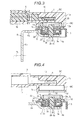
- the housing 1 is formed of a synthetic resin. As illustrated in Figs. 3 and 4 , the housing 1 has a main body portion 1a and a joint 1b. An element chamber SC is formed in the main body portion 1 a. At least the magneto-electric conversion element 10 is accommodated in the main body portion 1a. In addition, a magnet chamber MC is formed separately from the element chamber SC in the main body portion 1 a. The main body portion 1a is bonded to the supporting member 3, which is formed of a synthetic resin, such that the magnet member 20 is accommodated at a position in the magnet chamber MC which faces the magneto-electric conversion element 10.
- the joint 1 b is integrally formed with the main body portion 1 a, and the joint 1 b is configured such that the element chamber SC communicates with an external space only via the joint 1 b. Accordingly, when the connector member 5 is fitted into the joint 1 b in a liquid-tight manner, the element chamber SC becomes a sealed space.
- the housing 1 according to this embodiment has a cylindrical portion 1 c that integrally extends from the main body portion 1 a. When laser welding is performed over the entire circumference of the cylindrical portion 1 c, for example, the cylindrical portion 1 c is bonded to the supporting member 3 in close contact with the supporting member 3 and the magnet chamber MC is shielded from the external space.
- a bearing portion 3a that rotatably supports the shaft member 2 is formed in the supporting member 3 and an annular recessed portion 3b is formed around the bearing portion 3a.
- An annular vertical wall 3c is formed around the annular recessed portion 3b.
- the vertical wall 3c is configured to be fitted into an inner peripheral surface of the cylindrical portion 1 c of the housing 1.
- a plurality of (four in this embodiment) projections 3d are formed to extend from the vertical wall 3c for positioning during the fitting of the vertical wall 3c into the cylindrical portion 1 c.
- Recessed portions 1 d that are fitted into the projections 3d are formed in the inner peripheral surface of the cylindrical portion 1 c.
- a locking projection 3e which has an arc shape in plan view, is formed to extend in the annular recessed portion 3b so as to lock an end portion 4a of the return spring 4.
- a pair of flanged portions 3f and 3f are formed outside the vertical wall 3c to extend in directions away from each other.
- Mounting holes 3g and 3g are formed in the respective flanged portions 3f and 3f.
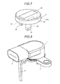
- the shaft member 2 has a disk portion 2a and a shaft portion 2b integrally formed with each other by a synthetic resin, and the magnet member 20 that is illustrated in Fig. 1 is embedded in the disk portion 2a.
- An engaging portion 2c that has a so-called dihedral width is formed at a tip of the shaft portion 2b and is configured to be engageable with an engaging hole 6c (refer to Fig. 9 ) which is formed in the driving lever 6 and has a dihedral width.
- An arc-shaped locking projection 2e is formed to extend from a lower surface of the disk portion 2a of the shaft member 2 so as to lock an end portion 4b of the return spring 4.
- the locking projection 2e has the plan-view positional relationship that is illustrated in Fig. 5 with respect to the locking projection 3e of the supporting member 3.
- the driving lever 6 has an extending portion 6a that extends in a radial direction of the shaft member 2 and an engaging portion 6b that extends in parallel to the axis of the shaft member 2 and is engaged with the external mechanism (pedal lever PL).
- the driving lever 6 is configured to drive the shaft member 2 to rotate against a biasing force of the return spring 4 with one end of the extending portion 6a fixed to the shaft member 2 and the other end of the extending portion 6a extending in the radial direction of the shaft member 2 (as a result of the engagement between the engaging hole 6c and the engaging portion 2c).
- the magnet member 20 has the above-described configuration ( Fig.
- the magneto-electric conversion element 10 has the pair of Hall ICs (not illustrated), a change in the angle of the parallel magnetic field that depends on the rotation of the shaft member 2, a change in the rotation angle of the magnet member 20 eventually, is detected by the pair of Hall ICs, and a voltage output in accordance with the magnetic field angle is supplied to external equipment (not illustrated) via the connector member 5.
- the recessed portions 1 d that are formed in the cylindrical portion 1 c of the housing 1 are fitted into the respective projections 3d that are formed on the vertical wall 3c of the supporting member 3, and the cylindrical portion 1c is fitted into the vertical wall 3c at a predetermined position. Then, laser welding is performed over the entire circumference of the cylindrical portion 1 c. In this manner, the housing 1 is bonded to the supporting member 3 in close contact with the supporting member 3, and the magnet chamber MC that is illustrated in Fig. 3 is formed.
- the magneto-electric conversion element 10 is accommodated in the main body portion 1a of the housing 1 for holding at a position facing the magneto-electric conversion element 10, the connector member 5 is electrically connected to the pair of Hall ICs (not illustrated) constituting the magneto-electric conversion element 10 in the main body portion 1 a, the connector member 5 is fitted into the joint 1 b in a liquid-tight manner, and the element chamber SC that is the sealed space is formed as illustrated in Fig. 3 .
- the engaging hole 6c of the driving lever 6 is engaged with and bonded to the engaging portion 2c of the shaft member 2, and the shaft member 2 is driven to rotate in response to an oscillation of the driving lever 6.
- the rotation angle detecting device that has the above-described configuration is placed such that the engaging portion 6b of the driving lever 6 is engaged with the pedal lever PL.
- the driving lever 6 is in a state of being pressed to the pedal lever PL by the biasing force of the return spring 4, and thus the pedal lever PL is held at an initial position that is set in advance.
- the pedal lever PL is operated in this state, the driving lever 6 oscillates about the axis of the shaft member 2 (shaft portion 2b) and the shaft member 2 is driven to rotate against the biasing force of the return spring 4. Accordingly, the magnet member 20 that is embedded in the disk portion 2a of the shaft member 2 rotates about the axis of the shaft portion 2b.
- the magnet member 20 that is supported by the supporting member 3 (which is integral with the housing 1) rotates relative to the magneto-electric conversion element 10 accommodated and supported in the housing 1, and the change in the angle of the parallel magnetic field that depends on the change in the rotation angle of the magnet member 20 is detected by the pair of Hall ICs in the magneto-electric conversion element 10. Then, the voltage output in accordance with the magnetic field angle is supplied to the external equipment (not illustrated) via the connector member 5.
- the magnet 200 that constitutes the magnet member 20 which is used in the rotation angle detecting device described above is formed as illustrated in Fig. 1 so that a parallel magnetic field detection region provided for the magneto-electric conversion element 10 is secured. Because the part where the groove 204 is formed in particular is thinner (smaller in volume) than the other parts and magnetic force lines concentrate in the vicinity of the groove 204, the region of the parallel magnetic field becomes wider at this part and a small and stable parallel magnetic field detection region is ensured. The following description will be based on the results of simulations performed on this embodiment and a magnet of the prior art, which are illustrated in Figs. 10A and 10B . The white section (non-hatched region) in Fig.
- FIG. 10A shows the region of the parallel magnetic field on an X-Z plane formed by the magnet member 20 of this embodiment (that is, a region parallel to the magnetization direction), and the white section (non-hatched region) in Fig. 10B shows the region of the parallel magnetic field on the X-Z plane formed by a disk magnet according to, for example, Reference 2.
- the rectangular solid-line region is the detection region.
- the hatched region that is not the parallel magnetic field
- the parallel magnetic field detection region is ensured with stability without being affected by an X-direction deviation.
- both are the same as each other, and thus description thereof will be omitted.
- a comparison between volumes of the magnets allowing a predetermined magnetic flux density at a point where the distances from the magnets are equal to each other shows that the volume of the magnet 200 according to this embodiment is one half or less of that of the disk magnet, and thus requires less magnet material and less manufacturing costs than the disk magnet.
- Figs. 11A and 11B show the region of the parallel magnetic field on the X-Z plane after the magnetization
- Fig. 11A pertaining to a case where the length (B) of the side of the magnet 200 on the short side is set to one-third of the length (A) of the side of the magnet 200 on the long side
- Fig. 11B pertaining to a case where the length (B) of the side of the magnet 200 on the short side is set to one half of the length (A) of the side of the magnet 200 on the long side, respectively.
- the rectangular solid-line region is the detection region. That in Fig. 11A is less likely to be affected by the X-direction deviation, and thus it is confirmed that the parallel magnetic field detection region is ensured with stability in this case.
- Fig. 12 shows results of simulations in which the width (D) of the groove 204 is set millimeter by millimeter within a range of 3 mm to 9 mm in a state where the length (A) of the side of the magnet 200 on the long side is fixed at 15 mm with regard to the setting of the width (D in Fig. 1 ) of the groove 204 with respect to the length (A in Fig. 1 ) of the side of the magnet 200 on the long side described above.
- the white sections (non-hatched regions) show the regions of the parallel magnetic field on the X-Z plane after the magnetization with respect to the respective ones of D from 3 to 9, and the rectangular solid-line region is the detection region.
- the width (D) of the groove 204 of the magnet 200 may be set to four-fifteenths to eight-fifteenths of the length (A) of the side of the magnet 200 on the long side, and the width (D) of the groove 204 is set, within this range, to one-third of the length (A) of the side of the magnet 200 on the long side in this embodiment.
Landscapes
- Physics & Mathematics (AREA)
- General Physics & Mathematics (AREA)
- Transmission And Conversion Of Sensor Element Output (AREA)
- Measurement Of Length, Angles, Or The Like Using Electric Or Magnetic Means (AREA)
Abstract
Description
- This disclosure relates to a rotation angle detecting device and, more particularly, to a rotation angle detecting device that detects a rotation angle of a shaft member in response to a relative rotation of a magnet member with respect to a magneto-electric conversion element.
- A non-contact rotation angle detecting device has been known in the prior art. The non-contact rotation angle detecting device detects a rotation angle of a shaft member in order to detect an operation amount of a brake pedal of a car or the like. The non-contact rotation angle detecting device has, for example, a magnet member that is placed in the shaft member to face a magneto-electric conversion element and is configured to detect the rotation angle of the shaft member in response to a relative rotation of the magnet member with respect to the magneto-electric conversion element. As an example,
JP 2007-139458A -
JP 2007-93280A - In
Reference 2 described above, the placement of the magneto-electric conversion elements is specified (described in Paragraph [0016]) for the purpose of "providing the rotation angle sensor that achieves cost reduction and structural simplification with the small magneto-electric conversion elements, allows the magneto-electric conversion element to be placed even at a position spaced apart from the center of the disk magnet, and is capable of suppressing an angular error attributable to a relative positional deviation between the magneto-electric conversion element and the disk magnet" (described in Paragraph [0015] of Reference 2). With regard to its specific configuration, the rotation angle sensor is configured, as disclosed inFig. 1 and described in Paragraphs [0020] and [0021], to be placed to face the X and Y Hall elements which are magneto-electric conversion elements, rotate the radially magnetized disk magnet so as to sense the subsequent horizontal magnetic field with the X and Y Hall elements placed at right angles to each other, and obtain the rotation angle from their output values. - However, in order to suppress the angular error attributable to the relative positional deviation between the magneto-electric conversion element and the disk magnet, not only the placement of the magneto-electric conversion element but also widening a parallel magnetic field provided for the magneto-electric conversion element to the maximum extent possible is effective. In order to reduce manufacturing costs, it is effective to ensure a magnetic flux density required for operating the Hall IC with a magnet that has a small volume. According to the specific configuration of the rotation angle detecting device described in
Reference 1 above, a pair of the Hall ICs are stored in a boss portion that is formed to protrude from a housing main body, a pivoting member that is tiltably linked to a shaft member which is pivotally supported by a cover member has a yoke main body and a magnet holder formed of a non-magnetic body material, and a permanent magnet is stored and supported inside the magnet holder as disclosed inFig. 2 ofReference 1 and described in Paragraphs [0013] to [0016] ofReference 1 while a relationship between the magneto-electric conversion element and the disk magnet according toReference 2 differs from that according toReference 1. - Thus, a need exists for a rotation angle detecting device including a magnet member placed in a shaft member to face a magneto-electric conversion element, detecting a rotation angle of the shaft member in response to a relative rotation of the magnet member with respect to the magneto-electric conversion element, and provided with the small magnet member capable of maximizing a region of a parallel magnetic field provided for the magneto-electric conversion element.
- A rotation angle detecting device according to an aspect of this disclosure is configured to include a magnet member placed in a shaft member to face a magneto-electric conversion element and detect a rotation angle of the shaft member in response to a relative rotation of the magnet member with respect to the magneto-electric conversion element, in which the magnet member has a magnet where a groove formed in a rectangular parallelepiped body having maximum surfaces orthogonal to an axis of the shaft member is formed to be open to one maximum surface side of the rectangular parallelepiped body and extend in parallel to a short-side lateral surface of the rectangular parallelepiped body, and is magnetized along the groove with respect to the magnet.
- In the above-described rotation angle detecting device, it is preferable that the groove of the magnet has a rectangular cross-sectional shape and is formed such that a long-side center of the rectangular cross-sectional shape extends in parallel to the short-side lateral surface of the rectangular parallelepiped body while including a center of a long-side lateral surface of the rectangular parallelepiped body. In addition, it is preferable that a width of the groove of the magnet is set to four-fifteenths to eight-fifteenths of a length of a side of the rectangular parallelepiped body on the long side. In addition, it is preferable that a depth of the groove of the magnet is set to one half of a thickness of the rectangular parallelepiped body.
- In addition, in the above-described rotation angle detecting device, it is preferable that the groove of the magnet is formed to be open to the maximum surface side of the magnet on a side opposite to a side placed to face the magneto-electric conversion element.
- In addition, it is preferable that a length of a side of the magnet on a short side of the rectangular parallelepiped body is set to one-third of the length of the side of the magnet on the long side of the rectangular parallelepiped body. In addition, it is preferable that the shaft member has a disk portion and a shaft portion integrally formed with each other, the disk portion being embedded such that a surface of the magnet member on a side facing the magneto-electric conversion element is exposed to a surface and the shaft portion vertically extending from a center of the disk portion.
- The aspect of this disclosure achieves the following effects based on the above-described configuration. In the rotation angle detecting device according to this disclosure, the magnet member is configured to have the magnet where the groove formed in the rectangular parallelepiped body having the maximum surfaces orthogonal to the axis of the shaft member is formed to be open to the one maximum surface side of the rectangular parallelepiped body and extend in parallel to the short-side lateral surface of the rectangular parallelepiped body, and be magnetized along the groove with respect to the magnet. Accordingly, the region of the parallel magnetic field provided for the magneto-electric conversion element can be widened by the small magnet member.
- In the above-described rotation angle detecting device, the region of the parallel magnetic field can be further widened insofar as the groove of the magnet has the rectangular cross-sectional shape and is formed such that the long-side center of the rectangular cross-sectional shape extends in parallel to the short-side lateral surface of the rectangular parallelepiped body while including the center of the long-side lateral surface of the rectangular parallelepiped body. In particular, the region of the parallel magnetic field can be ensured with stability insofar as the width of the groove of the magnet is set to four-fifteenths to eight-fifteenths of the length of the side of the rectangular parallelepiped body on the long side or the depth of the groove of the magnet is set to one half of the thickness of the rectangular parallelepiped body.
- In the above-described rotation angle detecting device, the region of the parallel magnetic field can be ensured with stability insofar as the groove of the magnet is formed to be open to the maximum surface side of the magnet on the side opposite to the side placed to face the magneto-electric conversion element. In addition, the region of the parallel magnetic field can be widened insofar as the length of the side of the magnet on the short side of the rectangular parallelepiped body is set to one-third of the length of the side of the magnet on the long side of the rectangular parallelepiped body. In addition, the magnet member can be appropriately placed with respect to the magneto-electric conversion element insofar as the shaft member has the disk portion and the shaft portion integrally formed with each other, the disk portion being embedded such that the surface of the magnet member on the side facing the magneto-electric conversion element is exposed to the surface and the shaft portion vertically extending from the center of the disk portion.
- The foregoing and additional features and characteristics of this disclosure will become more apparent from the following detailed description considered with the reference to the accompanying drawings, wherein:
-
Fig. 1 is a perspective view of a magnet member provided for an embodiment disclosed here; -
Fig. 2 is a plan view illustrating a relationship between the magnet member and a magneto-electric conversion element provided for the embodiment disclosed here; -
Fig. 3 is a cross-sectional view of a rotation angle detecting device according to the embodiment disclosed here; -
Fig. 4 is a cross-sectional view separately illustrating a housing and a supporting member provided for the embodiment disclosed here; -
Fig. 5 is a plan view illustrating the supporting member provided for the embodiment disclosed here; -
Fig. 6 is a plan view illustrating a state where a shaft member is mounted on the supporting member provided for the embodiment disclosed here; -
Fig. 7 is a perspective view illustrating the shaft member provided for the embodiment disclosed here; -
Fig. 8 is a perspective view illustrating the rotation angle detecting device according to the embodiment disclosed here; -
Fig. 9 is an exploded perspective view illustrating the rotation angle detecting device according to the embodiment disclosed here; -
Figs. 10A and 10B are distribution diagrams illustrating a comparison between parallel magnetic field region simulation results of the magnet member provided for the embodiment disclosed here and a magnet member of the prior art; -
Figs. 11A and 11B are distribution diagrams illustrating a comparison between parallel magnetic field region simulation results of the magnet member provided for the embodiment disclosed here and a comparative example; and -
Fig. 12 is a distribution diagram illustrating a comparison between the parallel magnetic field region simulation results of the magnet member provided for the embodiment disclosed here and the comparative example. - Hereinafter, a preferred embodiment disclosed here will be described with reference to accompanying drawings.
Figs. 1 to 9 relate to the embodiment disclosed here. -
Fig. 1 is an enlarged view of amagnet member 20 that is used in a non-contact rotation angle detecting device which detects a rotation angle of ashaft member 2 in response to a relative rotation of themagnet member 20 with respect to a magneto-electric conversion element 10 as illustrated inFig. 3 . As illustrated inFig. 1 , themagnet member 20 has amagnet 200 where agroove 204 is formed and is magnetized along thegroove 204 with respect to themagnet 200. With respect to a rectangular parallelepiped body that is configured to have maximum surfaces (shown as 201 on behalf of two parallel surfaces), long-side lateral surfaces (shown as 202 on behalf of two parallel surfaces), and short-side lateral surfaces (shown as 203 on behalf of two parallel surfaces), thegroove 204 is open to onemaximum surface 201 side and extends in parallel to the short-sidelateral surfaces 203. InFig. 1 , a white arrow MG shows the magnetization direction and (N) and (S) show magnetic poles after the magnetization. - In this embodiment, the length (B) of the side of the
magnet 200 on the short side is set to one-third of the length (A) of the side of themagnet 200 on the long side. Thegroove 204 of themagnet 200 has a rectangular cross-sectional shape and is formed such that the long-side center of thegroove 204 extends in parallel to the short-sidelateral surfaces 203 while including the center of the long-sidelateral surfaces 202. The width (D) of thegroove 204 is set to one-third of the length (A) of the side of themagnet 200 on the long side, and the depth (E) of thegroove 204 is set to one half of the thickness (C) of themagnet 200. As illustrated inFig. 1 , thegroove 204 is formed to be open to themaximum surface 201 side (lower side inFig. 1 ) of themagnet 200, which is the side opposite to the side that is placed to face the magneto-electric conversion element 10. As described later, the above-described dimensional relationships are set based on simulation results, are not limited to precise values, include approximate values, and may be approximately one half, approximately one-third, and the like. Nevertheless, it has been confirmed as described later that the width (D) of thegroove 204 can be subjected to use when set to four-fifteenths to eight-fifteenths of the length (A) of the side of themagnet 200 on the long side, and thus the width (D) of thegroove 204 is set, within this range, to one-third of the length (A) of the side of themagnet 200 on the long side as described above. - A parallel magnetic field is formed in the vicinity of the magneto-
electric conversion element 10 by themagnet member 20. When themagnet member 20 is driven to rotate about an axis (Z inFig. 1 ) of theshaft member 2, the parallel magnetic field that is formed by themagnet member 20 rotates relative to the magneto-electric conversion element 10 which has a fixed position (illustrated inFig. 3 ) as indicated by the arrows of one-dot chain line inFig. 2 , and an X-direction component Bx and a Y-direction component By of a magnetic field strength B at a rotation angle of, for example, θ are detected by the magneto-electric conversion element 10. Then, a signal that is proportional to the magnetic field direction is output from the magneto-electric conversion element 10, and the rotation angle θ is calculated. In a case where the position of the magneto-electric conversion element 10 is moved to the outside of a region of the parallel magnetic field (Pmf inFig. 2 ) due to backlash or the like, an error definitely ensues, and thus it is desirable that the region of the parallel magnetic field provided for the magneto-electric conversion element 10 is as wide as possible. Securing the region of the parallel magnetic field regarding this embodiment will be described later based on the simulation results that are illustrated inFigs. 10A to 12 . -
Figs. 3 to 9 show the rotation angle detecting device that is provided with themagnet member 20. The rotation angle detecting device serves to detect an operation amount of an external mechanism such as a brake pedal. The magneto-electric conversion element 10 is configured to have, for example, a pair of Hall ICs. A supportingmember 3 that rotatably supports theshaft member 2 is bonded to ahousing 1 that accommodates the magneto-electric conversion element 10. One end of a coil spring that constitutes areturn spring 4 is locked to theshaft member 2, and the other end of the coil spring is locked to the supportingmember 3. When aconnector member 5 such as a waterproof connector is bonded to thehousing 1, the magneto-electric conversion element 10 is electrically connected to theconnector member 5 and the magneto-electric conversion element 10 is sealed against the outside. Then, a drivinglever 6 is fixed to theshaft member 2 and is placed to be engaged with a pedal lever PL to constitute a brake pedal sensor. Hereinafter, each constituting member will be described in detail. - The
housing 1 is formed of a synthetic resin. As illustrated inFigs. 3 and 4 , thehousing 1 has amain body portion 1a and a joint 1b. An element chamber SC is formed in themain body portion 1 a. At least the magneto-electric conversion element 10 is accommodated in themain body portion 1a. In addition, a magnet chamber MC is formed separately from the element chamber SC in themain body portion 1 a. Themain body portion 1a is bonded to the supportingmember 3, which is formed of a synthetic resin, such that themagnet member 20 is accommodated at a position in the magnet chamber MC which faces the magneto-electric conversion element 10. The joint 1 b is integrally formed with themain body portion 1 a, and the joint 1 b is configured such that the element chamber SC communicates with an external space only via the joint 1 b. Accordingly, when theconnector member 5 is fitted into the joint 1 b in a liquid-tight manner, the element chamber SC becomes a sealed space. Thehousing 1 according to this embodiment has acylindrical portion 1 c that integrally extends from themain body portion 1 a. When laser welding is performed over the entire circumference of thecylindrical portion 1 c, for example, thecylindrical portion 1 c is bonded to the supportingmember 3 in close contact with the supportingmember 3 and the magnet chamber MC is shielded from the external space. - As illustrated in
Figs. 5 and 6 , a bearingportion 3a that rotatably supports theshaft member 2 is formed in the supportingmember 3 and an annular recessedportion 3b is formed around the bearingportion 3a. An annularvertical wall 3c is formed around the annular recessedportion 3b. Thevertical wall 3c is configured to be fitted into an inner peripheral surface of thecylindrical portion 1 c of thehousing 1. A plurality of (four in this embodiment)projections 3d are formed to extend from thevertical wall 3c for positioning during the fitting of thevertical wall 3c into thecylindrical portion 1 c. Recessedportions 1 d that are fitted into theprojections 3d are formed in the inner peripheral surface of thecylindrical portion 1 c. A lockingprojection 3e, which has an arc shape in plan view, is formed to extend in the annular recessedportion 3b so as to lock anend portion 4a of thereturn spring 4. A pair offlanged portions vertical wall 3c to extend in directions away from each other. Mountingholes flanged portions - As illustrated in
Fig. 7 , theshaft member 2 has adisk portion 2a and ashaft portion 2b integrally formed with each other by a synthetic resin, and themagnet member 20 that is illustrated inFig. 1 is embedded in thedisk portion 2a. An engagingportion 2c that has a so-called dihedral width is formed at a tip of theshaft portion 2b and is configured to be engageable with an engaginghole 6c (refer toFig. 9 ) which is formed in the drivinglever 6 and has a dihedral width. An arc-shapedlocking projection 2e is formed to extend from a lower surface of thedisk portion 2a of theshaft member 2 so as to lock anend portion 4b of thereturn spring 4. The lockingprojection 2e has the plan-view positional relationship that is illustrated inFig. 5 with respect to the lockingprojection 3e of the supportingmember 3. - The driving
lever 6 has an extendingportion 6a that extends in a radial direction of theshaft member 2 and anengaging portion 6b that extends in parallel to the axis of theshaft member 2 and is engaged with the external mechanism (pedal lever PL). The drivinglever 6 is configured to drive theshaft member 2 to rotate against a biasing force of thereturn spring 4 with one end of the extendingportion 6a fixed to theshaft member 2 and the other end of the extendingportion 6a extending in the radial direction of the shaft member 2 (as a result of the engagement between the engaginghole 6c and the engagingportion 2c). Themagnet member 20 has the above-described configuration (Fig. 1 ), the magneto-electric conversion element 10 has the pair of Hall ICs (not illustrated), a change in the angle of the parallel magnetic field that depends on the rotation of theshaft member 2, a change in the rotation angle of themagnet member 20 eventually, is detected by the pair of Hall ICs, and a voltage output in accordance with the magnetic field angle is supplied to external equipment (not illustrated) via theconnector member 5. - An assembly process for the rotation angle detecting device will be described with reference to
Fig. 9 . Firstly, thereturn spring 4 is accommodated in the annular recessedportion 3b of the supportingmember 3 and theend portion 4a of thereturn spring 4 is locked to the lockingprojection 3e. Then, the state that is illustrated in the lower section ofFig. 4 is achieved when thedisk portion 2a of theshaft member 2 is accommodated in the annularvertical wall 3c with theshaft portion 2b of theshaft member 2 accommodated in the bearingportion 3a of the supportingmember 3 and theend portion 4b of thereturn spring 4 locked to the lockingprojection 2e of theshaft member 2. In this state, thehousing 1 that is illustrated in the upper section ofFig. 4 is bonded to the supportingmember 3. In other words, the recessedportions 1 d that are formed in thecylindrical portion 1 c of thehousing 1 are fitted into therespective projections 3d that are formed on thevertical wall 3c of the supportingmember 3, and thecylindrical portion 1c is fitted into thevertical wall 3c at a predetermined position. Then, laser welding is performed over the entire circumference of thecylindrical portion 1 c. In this manner, thehousing 1 is bonded to the supportingmember 3 in close contact with the supportingmember 3, and the magnet chamber MC that is illustrated inFig. 3 is formed. - Then, the magneto-
electric conversion element 10 is accommodated in themain body portion 1a of thehousing 1 for holding at a position facing the magneto-electric conversion element 10, theconnector member 5 is electrically connected to the pair of Hall ICs (not illustrated) constituting the magneto-electric conversion element 10 in themain body portion 1 a, theconnector member 5 is fitted into the joint 1 b in a liquid-tight manner, and the element chamber SC that is the sealed space is formed as illustrated inFig. 3 . In addition, the engaginghole 6c of the drivinglever 6 is engaged with and bonded to the engagingportion 2c of theshaft member 2, and theshaft member 2 is driven to rotate in response to an oscillation of the drivinglever 6. - As illustrated in
Fig. 3 , the rotation angle detecting device that has the above-described configuration is placed such that the engagingportion 6b of the drivinglever 6 is engaged with the pedal lever PL. In this case, the drivinglever 6 is in a state of being pressed to the pedal lever PL by the biasing force of thereturn spring 4, and thus the pedal lever PL is held at an initial position that is set in advance. When the pedal lever PL is operated in this state, the drivinglever 6 oscillates about the axis of the shaft member 2 (shaft portion 2b) and theshaft member 2 is driven to rotate against the biasing force of thereturn spring 4. Accordingly, themagnet member 20 that is embedded in thedisk portion 2a of theshaft member 2 rotates about the axis of theshaft portion 2b. In other words, themagnet member 20 that is supported by the supporting member 3 (which is integral with the housing 1) rotates relative to the magneto-electric conversion element 10 accommodated and supported in thehousing 1, and the change in the angle of the parallel magnetic field that depends on the change in the rotation angle of themagnet member 20 is detected by the pair of Hall ICs in the magneto-electric conversion element 10. Then, the voltage output in accordance with the magnetic field angle is supplied to the external equipment (not illustrated) via theconnector member 5. - The
magnet 200 that constitutes themagnet member 20 which is used in the rotation angle detecting device described above is formed as illustrated inFig. 1 so that a parallel magnetic field detection region provided for the magneto-electric conversion element 10 is secured. Because the part where thegroove 204 is formed in particular is thinner (smaller in volume) than the other parts and magnetic force lines concentrate in the vicinity of thegroove 204, the region of the parallel magnetic field becomes wider at this part and a small and stable parallel magnetic field detection region is ensured. The following description will be based on the results of simulations performed on this embodiment and a magnet of the prior art, which are illustrated inFigs. 10A and 10B . The white section (non-hatched region) inFig. 10A shows the region of the parallel magnetic field on an X-Z plane formed by themagnet member 20 of this embodiment (that is, a region parallel to the magnetization direction), and the white section (non-hatched region) inFig. 10B shows the region of the parallel magnetic field on the X-Z plane formed by a disk magnet according to, for example,Reference 2. - In both
Figs. 10A and 10B , the rectangular solid-line region is the detection region. InFig. 10A , however, the hatched region (that is not the parallel magnetic field) is not included, and thus it can be appreciated that the parallel magnetic field detection region is ensured with stability without being affected by an X-direction deviation. When it comes to the Y direction, both are the same as each other, and thus description thereof will be omitted. A comparison between volumes of the magnets allowing a predetermined magnetic flux density at a point where the distances from the magnets are equal to each other shows that the volume of themagnet 200 according to this embodiment is one half or less of that of the disk magnet, and thus requires less magnet material and less manufacturing costs than the disk magnet. - Results of simulations performed while the shape of the
magnet 200 according to this embodiment is determined will be described below. The white sections (non-hatched regions) inFigs. 11A and 11B show the region of the parallel magnetic field on the X-Z plane after the magnetization,Fig. 11A pertaining to a case where the length (B) of the side of themagnet 200 on the short side is set to one-third of the length (A) of the side of themagnet 200 on the long side andFig. 11B pertaining to a case where the length (B) of the side of themagnet 200 on the short side is set to one half of the length (A) of the side of themagnet 200 on the long side, respectively. InFigs. 11A and 11B , the rectangular solid-line region is the detection region. That inFig. 11A is less likely to be affected by the X-direction deviation, and thus it is confirmed that the parallel magnetic field detection region is ensured with stability in this case. -
Fig. 12 shows results of simulations in which the width (D) of thegroove 204 is set millimeter by millimeter within a range of 3 mm to 9 mm in a state where the length (A) of the side of themagnet 200 on the long side is fixed at 15 mm with regard to the setting of the width (D inFig. 1 ) of thegroove 204 with respect to the length (A inFig. 1 ) of the side of themagnet 200 on the long side described above. In this drawing, the white sections (non-hatched regions) show the regions of the parallel magnetic field on the X-Z plane after the magnetization with respect to the respective ones of D from 3 to 9, and the rectangular solid-line region is the detection region. It is confirmed from the results that the parallel magnetic field can be ensured within the range of use in a case where D is 4 to 8 and it is not ensured within the range of use in a case where D is 3 or 9 as illustrated inFig. 12 . Accordingly, the width (D) of thegroove 204 of themagnet 200 may be set to four-fifteenths to eight-fifteenths of the length (A) of the side of themagnet 200 on the long side, and the width (D) of thegroove 204 is set, within this range, to one-third of the length (A) of the side of themagnet 200 on the long side in this embodiment. - The principles, preferred embodiment and mode of operation of the present invention have been described in the foregoing specification. However, the invention which is intended to be protected is not to be construed as limited to the particular embodiments disclosed. Further, the embodiments described herein are to be regarded as illustrative rather than restrictive. Variations and changes may be made by others, and equivalents employed. Accordingly, it is expressly intended that all such variations, changes and equivalents which fall within the scope of the present invention as defined in the claims, be embraced thereby.
Claims (7)
- A rotation angle detecting device comprising:a magnet member (20) placed in a shaft member (2) to face a magneto-electric conversion element (10) and detecting a rotation angle of the shaft member in response to a relative rotation of the magnet member (20) with respect to the magneto-electric conversion element (10),wherein the magnet member has a magnet (200) where a groove (204) formed in a rectangular parallelepiped body having maximum surfaces (201) orthogonal to an axis of the shaft member (2) is formed to be open to one maximum surface side of the rectangular parallelepiped body and extend in parallel to a short-side lateral surface (203) of the rectangular parallelepiped body, and is magnetized along the groove (204) with respect to the magnet (200).
- The rotation angle detecting device according to claim 1,
wherein the groove (204) of the magnet (200) has a rectangular cross-sectional shape and is formed such that a long-side center of the rectangular cross-sectional shape extends in parallel to the short-side lateral surface (203) of the rectangular parallelepiped body while including a center of a long-side lateral surface (202) of the rectangular parallelepiped body. - The rotation angle detecting device according to claim 2,
wherein a width (D) of the groove (204) of the magnet (200) is set to four-fifteenths to eight-fifteenths of a length (A) of a side of the rectangular parallelepiped body on the long side. - The rotation angle detecting device according to claim 2 or 3,
wherein a depth (E) of the groove (204) of the magnet (200) is set to one half of a thickness (C) of the rectangular parallelepiped body. - The rotation angle detecting device according to any one of claims 1 to 4,
wherein the groove (204) of the magnet (200) is formed to be open to the maximum surface side of the magnet (200) on a side opposite to a side placed to face the magneto-electric conversion element (10). - The rotation angle detecting device according to any one of claims 1 to 5,
wherein a length (B) of a side of the magnet on a short side of the rectangular parallelepiped body is set to one-third of the length (A) of the side of the magnet on the long side of the rectangular parallelepiped body. - The rotation angle detecting device according to any one of claims 1 to 6,
wherein the shaft member (2) has a disk portion (2a) and a shaft portion (2b) integrally formed with each other, the disk portion (2a) being embedded such that a surface of the magnet member (20) on a side facing the magneto-electric conversion element (10) is exposed to a surface and the shaft portion (2b) vertically extending from a center of the disk portion (2a).
Applications Claiming Priority (1)
| Application Number | Priority Date | Filing Date | Title |
|---|---|---|---|
| JP2014235421A JP2016099190A (en) | 2014-11-20 | 2014-11-20 | Rotation angle detector |
Publications (2)
| Publication Number | Publication Date |
|---|---|
| EP3023745A1 true EP3023745A1 (en) | 2016-05-25 |
| EP3023745B1 EP3023745B1 (en) | 2017-05-03 |
Family
ID=54695579
Family Applications (1)
| Application Number | Title | Priority Date | Filing Date |
|---|---|---|---|
| EP15195647.1A Not-in-force EP3023745B1 (en) | 2014-11-20 | 2015-11-20 | Rotation angle detecting device |
Country Status (4)
| Country | Link |
|---|---|
| US (1) | US9631949B2 (en) |
| EP (1) | EP3023745B1 (en) |
| JP (1) | JP2016099190A (en) |
| CN (1) | CN105627910A (en) |
Cited By (1)
| Publication number | Priority date | Publication date | Assignee | Title |
|---|---|---|---|---|
| EP3404367A1 (en) * | 2017-05-18 | 2018-11-21 | Tyco Electronics (Shanghai) Co. Ltd. | Sensing system for sensing a position of a gear shaft |
Families Citing this family (7)
| Publication number | Priority date | Publication date | Assignee | Title |
|---|---|---|---|---|
| CN109073413B (en) * | 2016-04-29 | 2021-10-08 | Tdk-迈克纳斯有限责任公司 | Distance measuring equipment |
| JP2018021795A (en) * | 2016-08-02 | 2018-02-08 | アイシン精機株式会社 | Rotation angle detector |
| JP6671269B2 (en) * | 2016-09-21 | 2020-03-25 | アルプスアルパイン株式会社 | Rotary input device |
| JP2018119920A (en) * | 2017-01-27 | 2018-08-02 | アイシン精機株式会社 | Magnet unit for sensor |
| US11280636B2 (en) * | 2018-07-09 | 2022-03-22 | Sensata Technologies, Inc. | Rotary position sensor and method of manufacturing the same |
| JP7226105B2 (en) * | 2019-05-30 | 2023-02-21 | 株式会社アイシン | Fixed structure |
| TWI774606B (en) * | 2021-11-09 | 2022-08-11 | 承康科技有限公司 | Magnetic angle detector |
Citations (5)
| Publication number | Priority date | Publication date | Assignee | Title |
|---|---|---|---|---|
| US4712064A (en) * | 1984-07-20 | 1987-12-08 | Robert Bosch Gmbh | Magnetoresistive sensor for detecting position or speed of a ferromagnetic body |
| US20010015642A1 (en) * | 2000-02-22 | 2001-08-23 | Roland Fischer | Mechanical shaft with integrated magnet arrangement |
| US20040189288A1 (en) * | 2003-03-31 | 2004-09-30 | Denso Corporation | Rotation angle detecting device |
| JP2007093280A (en) | 2005-09-27 | 2007-04-12 | Asahi Kasei Electronics Co Ltd | Rotation angle sensor |
| JP2007139458A (en) | 2005-11-15 | 2007-06-07 | Aisin Seiki Co Ltd | Rotation angle detector |
Family Cites Families (19)
| Publication number | Priority date | Publication date | Assignee | Title |
|---|---|---|---|---|
| JPS616412Y2 (en) * | 1980-12-26 | 1986-02-26 | ||
| US6414482B1 (en) * | 1999-11-11 | 2002-07-02 | Aisan Kogyo Kabushiki Kaisha | Non-contact type rotational angle sensor and sensor core used in the sensor |
| DE602004023556D1 (en) * | 2003-05-28 | 2009-11-26 | Aisin Seiki | Electrically driven pump |
| FR2866111B1 (en) * | 2004-02-11 | 2006-05-05 | Johnson Controls Tech Co | MAGNETIC SENSOR WITH ANGULAR POSITION |
| DE102005011090A1 (en) * | 2005-03-08 | 2006-09-14 | Bourns, Inc., Riverside | Rotation angle sensor for absolute angular measurement of angular position of rotating wave has cuboid shape magnet which has cuboid shape section, made of non magnetic material whereby sensor is arranged centrally to axis of rotation |
| CN100485322C (en) * | 2006-03-02 | 2009-05-06 | 光洋电子工业株式会社 | Magnetic encoder |
| JP5483516B2 (en) * | 2006-09-20 | 2014-05-07 | 旭化成エレクトロニクス株式会社 | POSITION DETECTION DEVICE, OPTICAL SYSTEM HAVING POSITION DETECTION DEVICE, AND IMAGING DEVICE |
| JP4947321B2 (en) * | 2009-07-30 | 2012-06-06 | Tdk株式会社 | Rotation angle detector |
| JP5105266B2 (en) * | 2010-06-02 | 2012-12-26 | 株式会社デンソー | Rotation angle detector |
| US8773116B2 (en) * | 2010-09-03 | 2014-07-08 | Panasonic Corporation | Rotation angle detecting device |
| JP5293724B2 (en) * | 2010-11-02 | 2013-09-18 | アイシン精機株式会社 | Angle detector |
| JP5497621B2 (en) * | 2010-12-16 | 2014-05-21 | アルプス電気株式会社 | Rotation angle detector |
| JP5141780B2 (en) * | 2011-01-12 | 2013-02-13 | Tdk株式会社 | Rotation angle sensor |
| JP2013002835A (en) * | 2011-06-13 | 2013-01-07 | Asahi Kasei Electronics Co Ltd | Rotation angle detecting device |
| KR20130010993A (en) * | 2011-07-20 | 2013-01-30 | 엘지이노텍 주식회사 | Height sensor module for vehicle |
| JP2013181937A (en) * | 2012-03-05 | 2013-09-12 | Panasonic Corp | Rotation angle detection device |
| US9134200B2 (en) * | 2012-08-17 | 2015-09-15 | Cts Corporation | Motor vehicle chassis sensor |
| DE102013000431A1 (en) * | 2013-01-14 | 2014-07-17 | Micronas Gmbh | Circuit and measuring system |
| DE102013000430A1 (en) * | 2013-01-14 | 2014-07-17 | Micronas Gmbh | measuring system |
-
2014
- 2014-11-20 JP JP2014235421A patent/JP2016099190A/en active Pending
-
2015
- 2015-11-19 CN CN201510802071.8A patent/CN105627910A/en active Pending
- 2015-11-19 US US14/945,955 patent/US9631949B2/en not_active Expired - Fee Related
- 2015-11-20 EP EP15195647.1A patent/EP3023745B1/en not_active Not-in-force
Patent Citations (5)
| Publication number | Priority date | Publication date | Assignee | Title |
|---|---|---|---|---|
| US4712064A (en) * | 1984-07-20 | 1987-12-08 | Robert Bosch Gmbh | Magnetoresistive sensor for detecting position or speed of a ferromagnetic body |
| US20010015642A1 (en) * | 2000-02-22 | 2001-08-23 | Roland Fischer | Mechanical shaft with integrated magnet arrangement |
| US20040189288A1 (en) * | 2003-03-31 | 2004-09-30 | Denso Corporation | Rotation angle detecting device |
| JP2007093280A (en) | 2005-09-27 | 2007-04-12 | Asahi Kasei Electronics Co Ltd | Rotation angle sensor |
| JP2007139458A (en) | 2005-11-15 | 2007-06-07 | Aisin Seiki Co Ltd | Rotation angle detector |
Cited By (1)
| Publication number | Priority date | Publication date | Assignee | Title |
|---|---|---|---|---|
| EP3404367A1 (en) * | 2017-05-18 | 2018-11-21 | Tyco Electronics (Shanghai) Co. Ltd. | Sensing system for sensing a position of a gear shaft |
Also Published As
| Publication number | Publication date |
|---|---|
| US20160146633A1 (en) | 2016-05-26 |
| CN105627910A (en) | 2016-06-01 |
| JP2016099190A (en) | 2016-05-30 |
| US9631949B2 (en) | 2017-04-25 |
| EP3023745B1 (en) | 2017-05-03 |
Similar Documents
| Publication | Publication Date | Title |
|---|---|---|
| EP3023745B1 (en) | Rotation angle detecting device | |
| US10110816B2 (en) | Optical unit with shake correction function | |
| US8222782B2 (en) | Brushless motor | |
| JP6426860B2 (en) | Magnet type angular displacement measurement system | |
| JP5983494B2 (en) | Liquid level detector | |
| EP3023744A1 (en) | Rotation angle detecting device | |
| US11906300B2 (en) | Absolute encoder | |
| WO2016158978A1 (en) | Motor and electric power steering device | |
| JP2010093869A (en) | Motor | |
| JP2005241269A (en) | Angle sensor | |
| WO2008075620A1 (en) | Rotation angle detection device | |
| CN108981858B (en) | Liquid level detection device | |
| JP6988851B2 (en) | Manufacturing method of magnetic field generation unit, position detection device and magnetic field generation unit | |
| JP2009085913A (en) | Position detector | |
| US20220170731A1 (en) | Absolute encoder | |
| JP6282010B2 (en) | Position detection device | |
| CN108474668B (en) | position detection device | |
| JP5663134B2 (en) | Liquid level sensor | |
| CN116399221B (en) | Rotation angle sensor and parking lock sensor using it | |
| JP2009098005A (en) | Position detector | |
| JP2018046200A (en) | Element unit | |
| JP2016082787A (en) | Motor and driving device | |
| JP2005195471A (en) | Rotation angle detecting device | |
| JP6451252B2 (en) | Rotation angle detector | |
| JP7226105B2 (en) | Fixed structure |
Legal Events
| Date | Code | Title | Description |
|---|---|---|---|
| AK | Designated contracting states |
Kind code of ref document: A1 Designated state(s): AL AT BE BG CH CY CZ DE DK EE ES FI FR GB GR HR HU IE IS IT LI LT LU LV MC MK MT NL NO PL PT RO RS SE SI SK SM TR |
|
| AX | Request for extension of the european patent |
Extension state: BA ME |
|
| PUAI | Public reference made under article 153(3) epc to a published international application that has entered the european phase |
Free format text: ORIGINAL CODE: 0009012 |
|
| 17P | Request for examination filed |
Effective date: 20160617 |
|
| RBV | Designated contracting states (corrected) |
Designated state(s): AL AT BE BG CH CY CZ DE DK EE ES FI FR GB GR HR HU IE IS IT LI LT LU LV MC MK MT NL NO PL PT RO RS SE SI SK SM TR |
|
| GRAP | Despatch of communication of intention to grant a patent |
Free format text: ORIGINAL CODE: EPIDOSNIGR1 |
|
| INTG | Intention to grant announced |
Effective date: 20170120 |
|
| RIN1 | Information on inventor provided before grant (corrected) |
Inventor name: FUSHIMI, SHINSUKE Inventor name: UENO, SHOUTA Inventor name: MATSUO, TOSHIYUKI |
|
| GRAS | Grant fee paid |
Free format text: ORIGINAL CODE: EPIDOSNIGR3 |
|
| GRAA | (expected) grant |
Free format text: ORIGINAL CODE: 0009210 |
|
| AK | Designated contracting states |
Kind code of ref document: B1 Designated state(s): AL AT BE BG CH CY CZ DE DK EE ES FI FR GB GR HR HU IE IS IT LI LT LU LV MC MK MT NL NO PL PT RO RS SE SI SK SM TR |
|
| REG | Reference to a national code |
Ref country code: GB Ref legal event code: FG4D |
|
| REG | Reference to a national code |
Ref country code: AT Ref legal event code: REF Ref document number: 890487 Country of ref document: AT Kind code of ref document: T Effective date: 20170515 Ref country code: CH Ref legal event code: EP |
|
| REG | Reference to a national code |
Ref country code: IE Ref legal event code: FG4D |
|
| REG | Reference to a national code |
Ref country code: DE Ref legal event code: R096 Ref document number: 602015002550 Country of ref document: DE |
|
| REG | Reference to a national code |
Ref country code: NL Ref legal event code: MP Effective date: 20170503 |
|
| REG | Reference to a national code |
Ref country code: AT Ref legal event code: MK05 Ref document number: 890487 Country of ref document: AT Kind code of ref document: T Effective date: 20170503 |
|
| REG | Reference to a national code |
Ref country code: LT Ref legal event code: MG4D |
|
| REG | Reference to a national code |
Ref country code: FR Ref legal event code: PLFP Year of fee payment: 3 |
|
| PG25 | Lapsed in a contracting state [announced via postgrant information from national office to epo] |
Ref country code: AT Free format text: LAPSE BECAUSE OF FAILURE TO SUBMIT A TRANSLATION OF THE DESCRIPTION OR TO PAY THE FEE WITHIN THE PRESCRIBED TIME-LIMIT Effective date: 20170503 Ref country code: NO Free format text: LAPSE BECAUSE OF FAILURE TO SUBMIT A TRANSLATION OF THE DESCRIPTION OR TO PAY THE FEE WITHIN THE PRESCRIBED TIME-LIMIT Effective date: 20170803 Ref country code: GR Free format text: LAPSE BECAUSE OF FAILURE TO SUBMIT A TRANSLATION OF THE DESCRIPTION OR TO PAY THE FEE WITHIN THE PRESCRIBED TIME-LIMIT Effective date: 20170804 Ref country code: HR Free format text: LAPSE BECAUSE OF FAILURE TO SUBMIT A TRANSLATION OF THE DESCRIPTION OR TO PAY THE FEE WITHIN THE PRESCRIBED TIME-LIMIT Effective date: 20170503 Ref country code: FI Free format text: LAPSE BECAUSE OF FAILURE TO SUBMIT A TRANSLATION OF THE DESCRIPTION OR TO PAY THE FEE WITHIN THE PRESCRIBED TIME-LIMIT Effective date: 20170503 Ref country code: LT Free format text: LAPSE BECAUSE OF FAILURE TO SUBMIT A TRANSLATION OF THE DESCRIPTION OR TO PAY THE FEE WITHIN THE PRESCRIBED TIME-LIMIT Effective date: 20170503 Ref country code: ES Free format text: LAPSE BECAUSE OF FAILURE TO SUBMIT A TRANSLATION OF THE DESCRIPTION OR TO PAY THE FEE WITHIN THE PRESCRIBED TIME-LIMIT Effective date: 20170503 |
|
| PG25 | Lapsed in a contracting state [announced via postgrant information from national office to epo] |
Ref country code: BG Free format text: LAPSE BECAUSE OF FAILURE TO SUBMIT A TRANSLATION OF THE DESCRIPTION OR TO PAY THE FEE WITHIN THE PRESCRIBED TIME-LIMIT Effective date: 20170803 Ref country code: SE Free format text: LAPSE BECAUSE OF FAILURE TO SUBMIT A TRANSLATION OF THE DESCRIPTION OR TO PAY THE FEE WITHIN THE PRESCRIBED TIME-LIMIT Effective date: 20170503 Ref country code: NL Free format text: LAPSE BECAUSE OF FAILURE TO SUBMIT A TRANSLATION OF THE DESCRIPTION OR TO PAY THE FEE WITHIN THE PRESCRIBED TIME-LIMIT Effective date: 20170503 Ref country code: RS Free format text: LAPSE BECAUSE OF FAILURE TO SUBMIT A TRANSLATION OF THE DESCRIPTION OR TO PAY THE FEE WITHIN THE PRESCRIBED TIME-LIMIT Effective date: 20170503 Ref country code: LV Free format text: LAPSE BECAUSE OF FAILURE TO SUBMIT A TRANSLATION OF THE DESCRIPTION OR TO PAY THE FEE WITHIN THE PRESCRIBED TIME-LIMIT Effective date: 20170503 Ref country code: IS Free format text: LAPSE BECAUSE OF FAILURE TO SUBMIT A TRANSLATION OF THE DESCRIPTION OR TO PAY THE FEE WITHIN THE PRESCRIBED TIME-LIMIT Effective date: 20170903 Ref country code: PL Free format text: LAPSE BECAUSE OF FAILURE TO SUBMIT A TRANSLATION OF THE DESCRIPTION OR TO PAY THE FEE WITHIN THE PRESCRIBED TIME-LIMIT Effective date: 20170503 |
|
| PG25 | Lapsed in a contracting state [announced via postgrant information from national office to epo] |
Ref country code: DK Free format text: LAPSE BECAUSE OF FAILURE TO SUBMIT A TRANSLATION OF THE DESCRIPTION OR TO PAY THE FEE WITHIN THE PRESCRIBED TIME-LIMIT Effective date: 20170503 Ref country code: RO Free format text: LAPSE BECAUSE OF FAILURE TO SUBMIT A TRANSLATION OF THE DESCRIPTION OR TO PAY THE FEE WITHIN THE PRESCRIBED TIME-LIMIT Effective date: 20170503 Ref country code: CZ Free format text: LAPSE BECAUSE OF FAILURE TO SUBMIT A TRANSLATION OF THE DESCRIPTION OR TO PAY THE FEE WITHIN THE PRESCRIBED TIME-LIMIT Effective date: 20170503 Ref country code: EE Free format text: LAPSE BECAUSE OF FAILURE TO SUBMIT A TRANSLATION OF THE DESCRIPTION OR TO PAY THE FEE WITHIN THE PRESCRIBED TIME-LIMIT Effective date: 20170503 Ref country code: SK Free format text: LAPSE BECAUSE OF FAILURE TO SUBMIT A TRANSLATION OF THE DESCRIPTION OR TO PAY THE FEE WITHIN THE PRESCRIBED TIME-LIMIT Effective date: 20170503 |
|
| REG | Reference to a national code |
Ref country code: DE Ref legal event code: R097 Ref document number: 602015002550 Country of ref document: DE |
|
| PG25 | Lapsed in a contracting state [announced via postgrant information from national office to epo] |
Ref country code: SM Free format text: LAPSE BECAUSE OF FAILURE TO SUBMIT A TRANSLATION OF THE DESCRIPTION OR TO PAY THE FEE WITHIN THE PRESCRIBED TIME-LIMIT Effective date: 20170503 Ref country code: IT Free format text: LAPSE BECAUSE OF FAILURE TO SUBMIT A TRANSLATION OF THE DESCRIPTION OR TO PAY THE FEE WITHIN THE PRESCRIBED TIME-LIMIT Effective date: 20170503 |
|
| PLBE | No opposition filed within time limit |
Free format text: ORIGINAL CODE: 0009261 |
|
| STAA | Information on the status of an ep patent application or granted ep patent |
Free format text: STATUS: NO OPPOSITION FILED WITHIN TIME LIMIT |
|
| 26N | No opposition filed |
Effective date: 20180206 |
|
| PG25 | Lapsed in a contracting state [announced via postgrant information from national office to epo] |
Ref country code: SI Free format text: LAPSE BECAUSE OF FAILURE TO SUBMIT A TRANSLATION OF THE DESCRIPTION OR TO PAY THE FEE WITHIN THE PRESCRIBED TIME-LIMIT Effective date: 20170503 |
|
| PG25 | Lapsed in a contracting state [announced via postgrant information from national office to epo] |
Ref country code: MC Free format text: LAPSE BECAUSE OF FAILURE TO SUBMIT A TRANSLATION OF THE DESCRIPTION OR TO PAY THE FEE WITHIN THE PRESCRIBED TIME-LIMIT Effective date: 20170503 |
|
| PG25 | Lapsed in a contracting state [announced via postgrant information from national office to epo] |
Ref country code: LU Free format text: LAPSE BECAUSE OF NON-PAYMENT OF DUE FEES Effective date: 20171120 |
|
| REG | Reference to a national code |
Ref country code: BE Ref legal event code: MM Effective date: 20171130 |
|
| REG | Reference to a national code |
Ref country code: IE Ref legal event code: MM4A |
|
| PG25 | Lapsed in a contracting state [announced via postgrant information from national office to epo] |
Ref country code: MT Free format text: LAPSE BECAUSE OF NON-PAYMENT OF DUE FEES Effective date: 20171120 |
|
| REG | Reference to a national code |
Ref country code: FR Ref legal event code: PLFP Year of fee payment: 4 |
|
| PG25 | Lapsed in a contracting state [announced via postgrant information from national office to epo] |
Ref country code: IE Free format text: LAPSE BECAUSE OF NON-PAYMENT OF DUE FEES Effective date: 20171120 |
|
| PG25 | Lapsed in a contracting state [announced via postgrant information from national office to epo] |
Ref country code: BE Free format text: LAPSE BECAUSE OF NON-PAYMENT OF DUE FEES Effective date: 20171130 |
|
| PGFP | Annual fee paid to national office [announced via postgrant information from national office to epo] |
Ref country code: DE Payment date: 20181106 Year of fee payment: 4 |
|
| PGFP | Annual fee paid to national office [announced via postgrant information from national office to epo] |
Ref country code: FR Payment date: 20181011 Year of fee payment: 4 |
|
| PG25 | Lapsed in a contracting state [announced via postgrant information from national office to epo] |
Ref country code: HU Free format text: LAPSE BECAUSE OF FAILURE TO SUBMIT A TRANSLATION OF THE DESCRIPTION OR TO PAY THE FEE WITHIN THE PRESCRIBED TIME-LIMIT; INVALID AB INITIO Effective date: 20151120 |
|
| REG | Reference to a national code |
Ref country code: CH Ref legal event code: PL |
|
| PG25 | Lapsed in a contracting state [announced via postgrant information from national office to epo] |
Ref country code: CH Free format text: LAPSE BECAUSE OF NON-PAYMENT OF DUE FEES Effective date: 20181130 Ref country code: LI Free format text: LAPSE BECAUSE OF NON-PAYMENT OF DUE FEES Effective date: 20181130 |
|
| PG25 | Lapsed in a contracting state [announced via postgrant information from national office to epo] |
Ref country code: CY Free format text: LAPSE BECAUSE OF FAILURE TO SUBMIT A TRANSLATION OF THE DESCRIPTION OR TO PAY THE FEE WITHIN THE PRESCRIBED TIME-LIMIT Effective date: 20170503 |
|
| PG25 | Lapsed in a contracting state [announced via postgrant information from national office to epo] |
Ref country code: MK Free format text: LAPSE BECAUSE OF FAILURE TO SUBMIT A TRANSLATION OF THE DESCRIPTION OR TO PAY THE FEE WITHIN THE PRESCRIBED TIME-LIMIT Effective date: 20170503 |
|
| PG25 | Lapsed in a contracting state [announced via postgrant information from national office to epo] |
Ref country code: TR Free format text: LAPSE BECAUSE OF FAILURE TO SUBMIT A TRANSLATION OF THE DESCRIPTION OR TO PAY THE FEE WITHIN THE PRESCRIBED TIME-LIMIT Effective date: 20170503 |
|
| PG25 | Lapsed in a contracting state [announced via postgrant information from national office to epo] |
Ref country code: PT Free format text: LAPSE BECAUSE OF FAILURE TO SUBMIT A TRANSLATION OF THE DESCRIPTION OR TO PAY THE FEE WITHIN THE PRESCRIBED TIME-LIMIT Effective date: 20170503 |
|
| REG | Reference to a national code |
Ref country code: DE Ref legal event code: R119 Ref document number: 602015002550 Country of ref document: DE |
|
| PG25 | Lapsed in a contracting state [announced via postgrant information from national office to epo] |
Ref country code: AL Free format text: LAPSE BECAUSE OF FAILURE TO SUBMIT A TRANSLATION OF THE DESCRIPTION OR TO PAY THE FEE WITHIN THE PRESCRIBED TIME-LIMIT Effective date: 20170503 |
|
| GBPC | Gb: european patent ceased through non-payment of renewal fee |
Effective date: 20191120 |
|
| PG25 | Lapsed in a contracting state [announced via postgrant information from national office to epo] |
Ref country code: GB Free format text: LAPSE BECAUSE OF NON-PAYMENT OF DUE FEES Effective date: 20191120 Ref country code: DE Free format text: LAPSE BECAUSE OF NON-PAYMENT OF DUE FEES Effective date: 20200603 Ref country code: FR Free format text: LAPSE BECAUSE OF NON-PAYMENT OF DUE FEES Effective date: 20191130 |