JP5983494B2 - Liquid level detector - Google Patents
Liquid level detector Download PDFInfo
- Publication number
- JP5983494B2 JP5983494B2 JP2013069336A JP2013069336A JP5983494B2 JP 5983494 B2 JP5983494 B2 JP 5983494B2 JP 2013069336 A JP2013069336 A JP 2013069336A JP 2013069336 A JP2013069336 A JP 2013069336A JP 5983494 B2 JP5983494 B2 JP 5983494B2
- Authority
- JP
- Japan
- Prior art keywords
- contact portion
- stopper
- holder
- contact
- support
- Prior art date
- Legal status (The legal status is an assumption and is not a legal conclusion. Google has not performed a legal analysis and makes no representation as to the accuracy of the status listed.)
- Active
Links
Images


Classifications
-
- G—PHYSICS
- G01—MEASURING; TESTING
- G01F—MEASURING VOLUME, VOLUME FLOW, MASS FLOW OR LIQUID LEVEL; METERING BY VOLUME
- G01F23/00—Indicating or measuring liquid level or level of fluent solid material, e.g. indicating in terms of volume or indicating by means of an alarm
- G01F23/30—Indicating or measuring liquid level or level of fluent solid material, e.g. indicating in terms of volume or indicating by means of an alarm by floats
- G01F23/32—Indicating or measuring liquid level or level of fluent solid material, e.g. indicating in terms of volume or indicating by means of an alarm by floats using rotatable arms or other pivotable transmission elements
- G01F23/38—Indicating or measuring liquid level or level of fluent solid material, e.g. indicating in terms of volume or indicating by means of an alarm by floats using rotatable arms or other pivotable transmission elements using magnetically actuated indicating means
Description
本発明は、容器に貯留されている液体の液面の高さを検出する液面検出装置に関する。 The present invention relates to a liquid level detection device that detects the height of a liquid level stored in a container.
従来、例えば特許文献1に開示のように、液面に浮かぶフロートと、フロートの上下移動により回転するフロートアーム及びアームホルダと、アームホルダを回転可能に支持するセンサフレームとを備えた液面検出装置が知られている。このような液面検出装置では、センサフレームに、ストッパ面が形成されている。ストッパ面は、フロートアームに設けられたストッパ係合部の回転軌道上に位置しており、ストッパ係合部と接触することによって、アームホルダの回転を規制する。 Conventionally, as disclosed in, for example, Patent Document 1, a liquid level detection including a float that floats on a liquid surface, a float arm and an arm holder that rotate when the float moves up and down, and a sensor frame that rotatably supports the arm holder The device is known. In such a liquid level detection device, a stopper surface is formed on the sensor frame. The stopper surface is located on the rotation track of the stopper engaging portion provided on the float arm, and regulates the rotation of the arm holder by contacting the stopper engaging portion.
加えて、特許文献1のセンサフレームには、ストッパ係合部の軸方向に沿って階段状に形成された三組のストッパ面が設けられている。こうした構成であれば、ストッパ係合部の長さを調整することにより、アームホルダの回転可能な範囲を、容器の形状に対応するように、予め規定された三段階のうちのいずれかに変更することができる。 In addition, the sensor frame of Patent Document 1 is provided with three sets of stopper surfaces formed in a step shape along the axial direction of the stopper engaging portion. In such a configuration, by adjusting the length of the stopper engaging portion, the rotatable range of the arm holder is changed to any one of the three stages defined in advance so as to correspond to the shape of the container. can do.
さて、特許文献1では、アームホルダの回転可能範囲を、三段階のうちのいずれかに調整可能ではあるものの、設定毎の回転可能範囲の差は、小さくない。そのため、アームホルダの回転可能範囲を、容器の形状に正しく対応させられない場合が生じ得た。こうした場合、適切な回転可能範囲が実現されるように、アームホルダ及びセンサフレーム等の形状を変更することが望ましい。 In Patent Document 1, although the rotatable range of the arm holder can be adjusted to any one of the three stages, the difference in the rotatable range for each setting is not small. Therefore, the case where the rotatable range of the arm holder cannot be made to correspond correctly to the shape of the container may occur. In such a case, it is desirable to change the shapes of the arm holder, the sensor frame, and the like so that an appropriate rotatable range is realized.
しかし、アームホルダのような回転体及びセンサフレームのような支持体は、一般に、様々な形状の容器に対応するよう構成された複数種類の液面検出装置によって共用されている。故に、特定の容器の形状に対応させるために、回転体及び支持体等の中核部品の形状を変更することは、実質的に不可能であった。 However, a rotating body such as an arm holder and a support body such as a sensor frame are generally shared by a plurality of types of liquid level detection devices configured to accommodate containers of various shapes. Therefore, it has been substantially impossible to change the shape of the core parts such as the rotating body and the support so as to correspond to the shape of a specific container.
本発明は、上記問題に鑑みてなされたものであって、その目的は、中核部品の形状を維持したまま、回転体の回転可能範囲を、容器の形状に対応するよう、任意に設定することが可能な液面検出装置を提供することである。 The present invention has been made in view of the above problems, and its purpose is to arbitrarily set the rotatable range of the rotating body to correspond to the shape of the container while maintaining the shape of the core part. It is to provide a liquid level detection device capable of performing the above.
上記目的を達成するために、請求項1に記載の発明は、容器(90)に貯留されている液体の液面の高さを検出する液面検出装置であって、液面に浮かぶフロート(55)と、フロートの上下移動により回転し、回転接触部(57)を有する回転体(50,56)と、回転体を回転可能に支持し、フロートを上昇又は下降させる特定方向(SRD)への回転体の回転を回転接触部との接触によって規制するよう、当該回転接触部の回転軌道上に位置する支持接触部(46a,46b)を有する支持体(40)と、支持体に取り付けられ、特定方向に回転する回転体と接触することによって支持接触部への回転接触部の接触を妨げる取付接触部(36,238,336)を有する取付部材(30,230,330)と、を備え、回転体における回転接触部の位置は、第一位置と、第一位置に対して回転体の径方向にずれた第二位置とのうちで変更可能であり、支持体は、第一位置に配置された回転接触部の回転軌道上に位置する支持接触部としての第一支持接触部、及び第一支持接触部に対してずれて配置され、第二位置に配置された回転接触部の回転軌道上に位置する第二支持接触部(48a,48b)を有し、取付接触部は、第二位置に配置された回転接触部が第二支持接触部を超えて特定方向に変位することにより、回転体と接触することを特徴としている。 In order to achieve the above object, the invention described in claim 1 is a liquid level detection device for detecting the height of a liquid level stored in a container (90), wherein the float (floating on the liquid level) 55) and a rotating body (50, 56) having a rotating contact portion (57) that rotates by the vertical movement of the float, and a specific direction (SRD) in which the rotating body is rotatably supported and the float is raised or lowered. to the rule the rotation of the rotating body regulations by the contact between the rotating contact part, supporting the contact portion located on the rotation path of the rotating contact unit and (46a, 46b) support having a (40), the support An attachment member (30, 230, 330) having an attachment contact portion (36, 238, 336) that prevents attachment of the rotation contact portion to the support contact portion by contacting a rotating body that rotates in a specific direction. In a rotating body The position of the rolling contact portion can be changed between the first position and the second position shifted in the radial direction of the rotating body with respect to the first position, and the support is a rotation arranged at the first position. A first support contact portion as a support contact portion located on the rotation track of the contact portion, and a position shifted on the rotation track of the rotation contact portion arranged at the second position, shifted from the first support contact portion. And the mounting contact portion is arranged so that the rotary contact portion disposed at the second position displaces in a specific direction beyond the second support contact portion, It is characterized by contact.
この発明によれば、支持体に取り付けられた取付部材の取付接触部は、回転体と接触することにより、支持接触部への回転接触部の接触を妨げる。故に、特定方向に回転した回転体は、回転接触部を、その回転軌道上に位置する支持接触部に接触させる以前に、取付接触部と接触する。これにより、回転体の回転可能な範囲は、狭められる。以上の構成であれば、取付部材に設ける取付接触部の形状及び配置を調整することにより、支持体のような中核部品の形状を維持したまま、回転体の回転可能範囲を、容器の形状に対応するよう、任意に設定することが可能となる。 According to this invention, the attachment contact portion of the attachment member attached to the support prevents contact of the rotational contact portion with the support contact portion by contacting the rotational body. Therefore, the rotating body rotated in a specific direction comes into contact with the attachment contact portion before the rotation contact portion is brought into contact with the support contact portion located on the rotation track. Thereby, the range which can rotate a rotary body is narrowed. With the above configuration, by adjusting the shape and arrangement of the mounting contact portion provided on the mounting member, the rotatable range of the rotating body can be changed to the shape of the container while maintaining the shape of the core part such as the support. It is possible to arbitrarily set so as to correspond.
尚、上記括弧内の参照番号は、本発明の理解を容易にすべく、後述する実施形態における具体的な構成との対応関係の一例を示すものにすぎず、本発明の範囲を何ら制限するものではない。 Note that the reference numbers in the parentheses are merely examples of correspondences with specific configurations in the embodiments to be described later in order to facilitate understanding of the present invention, and limit the scope of the present invention. It is not a thing.
以下、本発明の複数の実施形態を図面に基づいて説明する。尚、各実施形態において対応する構成要素には同一の符号を付すことにより、重複する説明を省略する場合がある。各実施形態において構成の一部分のみを説明している場合、当該構成の他の部分については、先行して説明した他の実施形態の構成を適用することができる。また、各実施形態の説明において明示している構成の組み合わせばかりではなく、特に組み合わせに支障が生じなければ、明示していなくても複数の実施形態の構成同士を部分的に組み合わせることができる。そして、複数の実施形態及び変形例に記述された構成同士の明示されていない組み合わせも、以下の説明によって開示されているものとする。 Hereinafter, a plurality of embodiments of the present invention will be described with reference to the drawings. In addition, the overlapping description may be abbreviate | omitted by attaching | subjecting the same code | symbol to the corresponding component in each embodiment. When only a part of the configuration is described in each embodiment, the configuration of the other embodiment described above can be applied to the other part of the configuration. Moreover, not only the combination of the configurations explicitly described in the description of each embodiment, but also the configuration of a plurality of embodiments can be partially combined even if they are not explicitly described, as long as there is no problem in the combination. And the combination where the structure described in several embodiment and the modification is not specified shall also be disclosed by the following description.
(第一実施形態)
図1に示す本発明の第一実施形態による液面検出モジュール100は、車両に搭載され、液体としての燃料を貯留する燃料タンク90内に設置されている。まず、液面検出モジュール100の構成を説明する。
(First embodiment)
A liquid
液面検出モジュール100は、フューエルセンダ10、燃料タンク90に取り付けられる蓋体20、及びフューエルセンダ10が取り付けられるホルダプレート30等によって構成されている。尚、以下の説明において、液面検出モジュール100を燃料タンク90内に挿入するために当該タンク90の天井部93に設けられた開口95の軸方向を、液面検出モジュール100の挿入方向IDとする。また、挿入方向IDと実質的に直交し且つホルダプレート30の平面方向に沿う方向を、幅方向WDとし、さらに、挿入方向IDと実質的に直交し且つホルダプレート30の板厚方向に沿う方向を、厚さ方向SDとする。
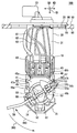
The liquid
図1,2に示すフューエルセンダ10は、燃料タンク90に貯留されている燃料の液面の高さを検出する。フューエルセンダ10は、フロート55、フロートアーム56、マグネットホルダ50、ボデー40、及びホールIC60等によって構成されている。
The
フロート55は、例えば発泡させたエボナイト等の燃料よりも比重の小さい材料により形成されている。フロート55は、燃料の液面に浮揚可能である。フロート55は、フロートアーム56を介してマグネットホルダ50に支持されている。
The
フロートアーム56は、ステンレス鋼等の金属材料からなる丸棒状の心材によって形成されている。フロートアーム56の両端部のうち、フロート55側の端部には、フロート保持部59が形成されている。フロート保持部59がフロート55の貫通孔に挿通されることで、フロートアーム56は、フロート55を保持している。フロートアーム56のマグネットホルダ50側の端部には、アーム接触部57が形成されている。アーム接触部57は、フロートアーム56をマグネットホルダ50の回転軸と同一方向且つボデー40側に90度程度屈曲させることによって形成されている。
The
マグネットホルダ50は、例えばポリアセタール(POM)樹脂等により円盤状に形成されている。マグネットホルダ50には、マグネット53が収容さている。マグネット53には、フランジ部51、ストッパ孔54a〜54c、及びアーム係止部52等が設けられている。
The
マグネット53は、永久磁石である。マグネット53は、マグネットホルダ50の周方向に沿って湾曲した板状に形成されている。マグネット53は、ボデー40の後述する支持軸45を挟んで一対配置されている。マグネット53は、マグネットホルダ50と一体でボデー40に対して相対回転する。
The
フランジ部51は、マグネットホルダ50に設けられた鍔状の部位である。フランジ部51には、ストッパ孔54a〜54cが形成されている。ストッパ孔54a〜54cは、マグネットホルダ50の軸方向に沿ってフランジ部51を貫通している。ストッパ孔54a〜54cは、マグネットホルダ50の径方向に沿って等間隔で並んでいる。
The
アーム係止部52は、フロートアーム56を係止するための爪部である。アーム係止部52は、フロートアーム56と接するマグネットホルダ50の軸方向の端面から延出している。ストッパ孔54a〜54cのいずれか一つにアーム接触部57を挿通させた状態で、アーム係止部52にフロートアーム56を係止させることにより、フロートアーム56は、マグネットホルダ50に固定される。
The
ボデー40は、例えばポリフェニレンサルファイド(PPS)樹脂等によって形成されている。ボデー40は、ホルダプレート30に組み付けられ、当該プレート30に保持されている。ボデー40は、底壁部41、支持軸45、及び周壁部43を有している。底壁部41は、板状に形成されており、ホルダプレート30に載置されている。支持軸45は、厚さ方向SDに沿って底壁部41から円柱状に突出している。支持軸45には、ホールIC60が収容されている。支持軸45にマグネットホルダの軸受部が外嵌されることにより、ボデー40は、マグネットホルダ50を回転自在に支持する。
The
周壁部43は、底壁部41の周縁部分から厚さ方向SDに沿って、マグネットホルダ50側に向けて立設されている。周壁部43において、幅方向WDに対向する二つの壁面には、複数組のストッパ面46a〜48bが形成されている。各ストッパ面46a〜48bは、それぞれマグネットホルダ50の径方向に沿って延びている。三組のストッパ面のうちで最も支持軸45に近接している広角ストッパ面46a,46bは、ストッパ孔54aに挿通されたアーム接触部57の回転軌道上に位置している。中間ストッパ面47a,47bは、広角ストッパ面46a,46bに対して、マグネットホルダ50の径方向外側にずれた位置に配置されている。中間ストッパ面47a,47bは、ストッパ孔54bに挿通されたアーム接触部57の回転軌道上に位置している。狭角ストッパ面48a,48bは、中間ストッパ面47a,47bに対して、マグネットホルダ50の径方向外側にずれた位置に配置されている。狭角ストッパ面48a,48bは、ストッパ孔54cに挿通されたアーム接触部57の回転軌道上に位置している。
The
以上の各ストッパ面46a〜48bは、アーム接触部57との接触によってマグネットホルダ50の回転を規制する。具体的に、周壁部43の一方の壁面に設けられた各ストッパ面46a,47a,48aは、フロート55を下降させる回転方向(以下、「特定方向SRD」という)へのマグネットホルダ50の回転によってアーム接触部57と当接する。こうして各ストッパ面46a,47a,48aは、マグネットホルダ50の特定方向SRDへの回転変位を規制することにより、燃料タンク90内の燃料残量がごく僅かの状態において、燃料タンク90の底面へのフロート55の接触を防止する。また、周壁部43の他方の壁面に設けられた各ストッパ面46b,47b,48bは、フロート55を上昇させる回転方向(以下、「反対方向RRD」という)へのマグネットホルダ50の回転によってアーム接触部57と当接する。こうして各ストッパ面46b,47b,48bは、マグネットホルダ50の反対方向RRDへの回転変位を規制することにより、燃料タンク90内に燃料が最大量充填された状態において、燃料タンク90の天井面へのフロート55の接触を防止する。
The stopper surfaces 46 a to 48 b described above restrict the rotation of the
ホールIC60は、液面の高さを検出するための検出素子である。ホールIC60は、支持軸45に対するマグネットホルダ50の回転角度を検出する。ホールIC60は、一対のマグネット53に挟まれるように、支持軸45内に配置されている。ホールIC60は、三つのリード線61〜63及びターミナル等を介して、燃料タンク90の外部の機器に接続されている。ホールIC60は、電圧を印加された状態で外部から磁界の作用を受けることにより、当該ホールIC60を通過する磁束の密度に比例した電圧を出力結果として、外部の機器へ向けて出力する。
The
以上の構成では、マグネットホルダ50に支持されたフロートアーム56によって、燃料に追従して上下移動するフロート55の往復動作は、回転運動に変換されてフロートアーム56およびマグネットホルダ50よりなる一体要素に伝達される。故に、マグネットホルダ50は、燃料タンク90に貯留される燃料の液面に追従し、ボデー40に対して相対回転する。このマグネットホルダ50の相対回転により、ホールIC60に作用する磁界の磁束密度が変化することで、ホールIC60から出力される電圧は変化する。こうしてフューエルセンダ10は、マグネットホルダ50の回転角度、ひいては燃料の液面の高さの検出を実現している。
In the above-described configuration, the reciprocating motion of the
図1に示す蓋体20は、樹脂材料等によって、開口95よりも大径の円盤状に形成されている。蓋体20は、開口95の周縁部分96に燃料タンク90の外側から液密に密着することにより、開口95を塞いでいる。蓋体20に設けられたコネクタ部23には、ホールIC60と外部の機器とを電気的に接続させるための相手側のコネクタ部(図示しない)が嵌合される。
The
図1,3に示すホルダプレート30は、燃料タンク90に対し、フューエルセンダ10のボデー40を固定する部材である。ホルダプレート30は、ボデー40を保持しており、且つ、蓋体20によって保持されている。ホルダプレート30は、鉄等の金属材料よりなる板材によって形成されている。ホルダプレート30は、ホルダ本体部31及びガード壁34,35を有している。
The
ホルダ本体部31は、挿入方向IDを長手とする長手形状に形成されている。ホルダ本体部31は、挿入方向IDに沿って蓋体20から延伸している。ホルダ本体部31は、ボデー40を挟んでマグネットホルダ50とは反対側に位置している。ホルダ本体部31は、各ガード壁34,35を支持している。
The holder
ガード壁34,35は、ホルダ本体部31の挿入方向IDの先端部分から、厚さ方向SDに沿ってボデー40側に板状に立設されている。一対のガード壁34,35は、幅方向WDにおいて互いに対向している。各ガード壁34,35は、挿入方向IDに向かうに従い、幅方向WDにおけるホルダ本体部31の中央に向かって傾斜している。
The
さて、図1に示す上述のフューエルセンダ10では、アーム接触部57を挿通させるストッパ孔54a〜54cを変えることにより、マグネットホルダ50の径方向におけるアーム接触部57の位置が変更可能である。こうしたアーム接触部57の位置変更によれば、マグネットホルダ50の回転可能な範囲(以下、「振れ角度」という)を調整することができる。尚、以下の説明では、最も内周側のストッパ孔54aに挿通されたアーム接触部57の位置を、広角位置という。また、最も外周側のストッパ孔54cに挿通されたアーム接触部57の位置を、狭角位置という。さらに、ストッパ孔54bに挿通されたアーム接触部57の位置を、中間位置という。
In the above-described
具体的に、広角位置に配置されたアーム接触部57は、広角ストッパ面46a,46bによって周方向への変位を規制される。この場合、マグネットホルダ50の触れ角度は、最も大きくなり、120度程度となる。また、中間位置に配置されたアーム接触部57は、中間ストッパ面47a,47bによって周方向への変位を規制される。この場合、マグネットホルダ50の振れ角度は、90度程度となる。さらに、狭角位置に配置されたアーム接触部57は、狭角ストッパ面48a,48bによって周方向への変位を規制される。この場合、マグネットホルダ50の振れ角度は、60度程度となる。
Specifically, the
以上のように、フューエルセンダ10においては、マグネットホルダ50の振れ角度を、三段階のうちのいずれかに調整可能ではある。しかし、設定毎の振れ角度の差は、小さくない。そのため、燃料タンク90の形状に振れ角度を正しく対応させられない場合が生じ得る。そこで、図3,4に示す如く、ホルダプレート30には、ホルダストッパ部36が設けられている。
As described above, in the
ホルダストッパ部36は、一方のガード壁35の頂上部分35aから厚さ方向SDに立設されている。ホルダストッパ部36は、ガード壁35と一体的に形成されている。ホルダストッパ部36は、ガード壁35と連続した板状に形成されており、板厚方向をマグネットホルダ50の回転中心に向けた姿勢で配置されている。ホルダストッパ部36の辺縁のうちで、幅方向WDの内側に位置する外縁部分37は、マグネットホルダ50の周方向に傾斜しつつ、当該ホルダ50の軸方向に延びている。
The
ここで、挿入方向IDに沿い、且つ、マグネットホルダ50の回転中心を通過する仮想線を、中心線CLとする。そして、厚さ方向SDに直交する仮想平面にて、中心線CLと、回転中心から広角ストッパ面46aに向かう仮想線とが特定方向SRDになす角度をαとする。また、中心線CLと、回転中心から狭角ストッパ面48aに向かう仮想線とが特定方向SRDになす角度をβとする。さらに、中心線CLと、回転中心から外縁部分37に向かう仮想線とが特定方向SRDになす角度をγとする。外縁部分37の位置を規定する角度γは、狭角ストッパ面48aの位置を規定する角度αよりも大きく、広角ストッパ面46aの位置を規定する角度βよりも小さくされている。
Here, a virtual line along the insertion direction ID and passing through the rotation center of the
ここまで説明した構成において、アーム接触部57が広角位置に配置された場合をまず説明する。こうした使用形態では、マグネットホルダ50が特定方向SRDに回転すると、フロートアーム56は、アーム接触部57を広角ストッパ面46aに接触させる以前に、中間部分58を外縁部分37に接触させる。このように、ホルダストッパ部36は、フロートアーム56と接触することにより、アーム接触部57の広角ストッパ面46aへの接触を妨げる。以上によれば、マグネットホルダ50の振れ角度は、ホルダプレート30にホルダストッパ部36が設けられない場合と比較して、狭められる。
First, the case where the
加えて、図5に示すように、外縁部分37が周方向に傾斜した形状であれば、ホルダストッパ部36を板厚方向に沿って外周側に倒すことにより、フロートアーム56の回転軌道ROAと外縁部分37との交点は、少なくとも特定方向SRDに移動する。こうして外縁部分37と中間部分58との接触位置CPが特定方向SRDに僅かにずれることにより、振れ角度の微調整が、可能となる。
In addition, as shown in FIG. 5, if the
次に、図6に示すように、アーム接触部57が狭角位置に配置された場合について、説明する。こうした使用形態では、通常、マグネットホルダ50が特定方向SRDに回転すると、フロートアーム56は、アーム接触部57を狭角ストッパ面48aに接触させる。そのため、中間部分58と外縁部分37との接触は、生じない。しかし、狭角ストッパ面48aの偶発的に損傷すると、アーム接触部57は、狭角ストッパ面48aを越えて、特定方向SRDに変位する場合がある。こうした場合、ホルダストッパ部36は、外縁部分37を中間部分58に接触させることができる。以上によれば、マグネットホルダ50の特定方向SRDへの回転が規制されるので、ボデー40からのアーム接触部57の離脱は、防止される。
Next, as shown in FIG. 6, the case where the
ここまで説明した第一実施形態によれば、ホルダストッパ部36がマグネットホルダ50の回転を規制することにより、ボデー40の広角ストッパ面46aに依らないで、振れ角度を規定することができる。以上によれば、ホルダストッパ部36の形状及び配置等を調整することで、ボデー40のような中核部品の形状を維持したまま、振れ角度を、燃料タンク90の形状に対応するよう、任意に設定することが可能となる。
According to the first embodiment described so far, the
加えて第一実施形態では、ホルダプレート30が金属材料によって形成されているため、ホルダストッパ部36の強度を低下させることなく、ホルダストッパ部36及びその近傍に塑性変形を生じさせることができる。こうした塑性変形によれば、上述したように、外縁部分37と中間部分58との接触位置CPの微調整が可能となる。したがって、液面検出モジュール100が実際に取り付けられる燃料タンク90の形状に、マグネットホルダ50の振れ角度を細かく合わせることができる。
In addition, in the first embodiment, since the
さらに、周方向に傾斜した外縁部分37の形状によれば、板厚方向にホルダストッパ部36を倒すような塑性変形により、外縁部分37と中間部分58との接触位置CPを特定方向SRDに移動させることができる。したがって、実際の燃料タンク90の形状に合わせた振れ角度の微調整が、確実且つ容易に実施可能となる。
Further, according to the shape of the
さらに加えて、第一実施形態における中間部分58は、板状に形成されたホルダストッパ部36の外縁部分37に、板面方向に沿って接触する。故に、ホルダストッパ部36は、特定方向SRDに回転しようとするマグネットホルダ50の力を、主に板面方向に沿って受けることができる。こうした構成であれば、ホルダストッパ部36は、マグネットホルダ50の回転を規制するために必要な強度を、確保され易くなる。したがって、ホルダストッパ部36によって規定されたマグネットホルダ50の振れ角度は、長期に亘って維持可能となる。
In addition, the
また第一実施形態につき、ストッパ孔54cに挿通されたアーム接触部57が、損傷した狭角ストッパ面48aを越えてしまった場合でも、マグネットホルダ50の特定方向SRDへの回転変位は、中間部分58の外縁部分37への接触により、規制される。こうしてボデー40からのフロートアーム56の離脱が防がれることにより、振れ角度の規定された状態は、維持され得る。したがって、狭角ストッパ面48aが偶発的に損傷しても、フューエルセンダ10は、液面高さを検出するための作動を継続できる。
Further, according to the first embodiment, even when the
さらに加えて第一実施形態では、燃料タンク90に対してボデー40を固定するためのホルダプレート30に、上述のホルダストッパ部36が設けられている。こうした構成であれば、振れ角度を規定するための別部品の追加が不要となる。よって、フューエルセンダ10の構成を複雑化することなく、振れ角度を、任意に設定することが可能となる。
In addition, in the first embodiment, the above-described
尚、第一実施形態において、ストッパ孔54aによって規定される広角位置が特許請求の範囲に記載の「第一位置」に相当し、ストッパ孔54cによって規定される狭角位置が特許請求の範囲に記載の「第二位置」に相当する。また、ホルダプレート30が特許請求の範囲に記載の「取付部材」に相当し、ホルダストッパ部36が特許請求の範囲に記載の「取付接触部」に相当する。さらに、ボデー40が特許請求の範囲に記載の「支持体」に相当し、広角ストッパ面46aが特許請求の範囲に記載の「支持接触部」及び「第一支持接触部」に相当し、狭角ストッパ面48a特許請求の範囲に記載の「第二支持接触部」に相当する。また、マグネットホルダ50及びフロートアーム56が特許請求の範囲に記載の「回転体」に相当し、アーム接触部57が特許請求の範囲に記載の「回転接触部」に相当する。そして、燃料タンク90が特許請求の範囲に記載の「容器」に相当し、液面検出モジュール100が特許請求の範囲に記載の「液面検出装置」に相当する。
In the first embodiment, the wide angle position defined by the
(第二実施形態)
図7,8に示す本発明の第二実施形態は、第一実施形態の変形例である。第二実施形態によるホルダプレート230には、第一実施形態のガード壁34,35(図3参照)に相当するガード壁234,235と、第一ストッパ壁236及び第二ストッパ壁238とが設けられている。以下、第二実施形態によるホルダプレート230の第一ストッパ壁236及び第二ストッパ壁238について詳細に説明する。
(Second embodiment)
The second embodiment of the present invention shown in FIGS. 7 and 8 is a modification of the first embodiment. The
第一ストッパ壁236及び第二ストッパ壁238は、ホルダ本体部31の辺縁部分から厚さ方向SDに立設されている。第一ストッパ壁236は、ガード壁234よりも幅方向WDの外側に位置している。第一ストッパ壁236は、幅方向WDに沿って板状に延設されている。第一ストッパ壁236の辺縁のうちで、幅方向WDの内側に位置する外縁部分237は、マグネットホルダ50の軸方向に沿って延伸している。
The
第二ストッパ壁238は、ガード壁235よりも幅方向WDの外側に位置している。第二ストッパ壁238は、挿入方向IDに沿って板状に延設されている。第二ストッパ壁238の辺縁のうちで、挿入方向IDに位置する外縁部分239は、マグネットホルダ50の軸方向に沿って延伸している。
The
以上の構成において、アーム接触部57を広角位置に配置した使用形態では、マグネットホルダ50が特定方向SRDに回転すると、フロートアーム56は、中間部分58を外縁部分239に接触させる。こうして第二ストッパ壁238は、フロートアーム56と接触することにより、アーム接触部57の広角ストッパ面46aへの接触を妨げ、特定方向SRDへのマグネットホルダ50の回転を規制する(図7を参照)。
In the above-described configuration, in the usage mode in which the
また、マグネットホルダ50が反対方向RRDに回転すると、フロートアーム56は、中間部分58を外縁部分237に接触させる。こうして第一ストッパ壁236は、フロートアーム56と接触することにより、アーム接触部57の広角ストッパ面46bへの接触を妨げ、反対方向RRDへのマグネットホルダ50の回転を規制する(図8を参照)。
Further, when the
以上のように、第二実施形態でも、ボデー40の広角ストッパ面46a,46bに依らないで、ホルダプレート230の振れ角度を規定することができる。故に、ボデー40のような中核部品の形状を維持したまま、振れ角度を、燃料タンク90(図1参照)の形状に対応するよう、任意に設定することが可能となる。
As described above, also in the second embodiment, the swing angle of the
加えて第二実施形態では、特定方向SRD及び反対方向RRDへのマグネットホルダ50の回転が、各ストッパ壁236,238によって、共に規制される。故に、各ストッパ壁236,238の形状及び配置の変更により、マグネットホルダ50の振れ角度は、さらに自在に規定可能となる。以上によれば、燃料タンク90(図1参照)の形状に振れ角度を合わせることが、いっそう容易となる。
In addition, in the second embodiment, the rotation of the
さらに第二実施形態では、第一ストッパ壁236の中央から板厚方向に沿って規定される仮想の軸線は、マグネットホルダ50の回転中心から外れた方向に向けられている。同様に、第二ストッパ壁238の中央から板厚方向に沿って規定される仮想の軸線は、マグネットホルダ50の回転中心から外れた方向に向けられている。以上のように、各板厚方向が回転中心から外れた方向に向けられていれば、各ストッパ壁236,238を各板厚方向に沿って倒すことにより、中間部分58と各外縁部分237,239との各接触位置CPは、特定方向SRD又は反対方向RRDにずれ得る。したがって、各ストッパ壁236,238を僅かに傾けるといった容易な工程で、実際の燃料タンク90(図1参照)の形状に合わせた振れ角度の微調整が、確実に実施可能となる。
Furthermore, in the second embodiment, a virtual axis defined along the thickness direction from the center of the
また第二実施形態では、アーム接触部57を狭角位置に配置した使用形態において、アーム接触部57が狭角ストッパ面48aを越えてしまった場合に、フロートアーム56は、中間部分58を外縁部分239に接触させることができる。同様に、ストッパ孔54cに挿通されたアーム接触部57が狭角ストッパ面48bを越えてしまった場合、フロートアーム56は、中間部分58を外縁部分237に接触させることができる。以上によれば、各狭角ストッパ面48a,48bが損傷した場合でも、マグネットホルダ50の特定方向SRD及び反対方向RRDへの回転は、共に規制される。故に、ボデー40からのアーム接触部57の離脱は、防止され得る。したがって、フューエルセンダ10は、液面高さを検出するための作動を継続できる。
In the second embodiment, in the usage pattern in which the
尚、第二実施形態において、ホルダプレート230が特許請求の範囲に記載の「取付部材」に相当し、第二ストッパ壁238が特許請求の範囲に記載の「取付接触部」に相当し、第一ストッパ壁236が特許請求の範囲に記載の「反対側接触部」に相当する。
In the second embodiment, the
(第三実施形態)
図9に示す本発明の第三実施形態は、第一実施形態の別の変形例である。第三実施形態によるホルダプレート330には、第一実施形態のホルダストッパ部36(図3参照)に相当する、ホルダストッパ部336が設けられている。以下、第三実施形態によるホルダプレート330のホルダストッパ部336について詳細に説明する。尚、第三実施形態では、フロート55(図1参照)を上昇させるマグネットホルダ50の回転方向を、特定方向SRDという。
(Third embodiment)
The third embodiment of the present invention shown in FIG. 9 is another modification of the first embodiment. The
ホルダストッパ部336は、第一実施形態のガード壁34(図3参照)と実質的同一であるガード壁334と一体的に形成されており、このガード壁334と連続した板状である。ホルダストッパ部336は、ガード壁334の頂上部分334aから厚さ方向SDに立設されている。ホルダストッパ部336は、板厚方向をマグネットホルダ50の回転中心に向けた姿勢で配置されている。ホルダストッパ部336の幅方向WDの内側には、マグネットホルダ50の軸方向に沿って延びる外縁部分337が形成されている。外縁部分337は、マグネットホルダ50の径方向外側に向けて屈曲されている。また、ホルダストッパ部336の頂上部分336aは、マグネットホルダ50の径方向外側に向けて屈曲されている。外縁部分337及び頂上部分336aによって形成されるリブにより、ホルダストッパ部336は、補強されている。
The
ここまで説明した構成において、アーム接触部57を広角位置に配置した使用形態では、マグネットホルダ50が特定方向SRDに回転すると、フロートアーム56は、中間部分58を外縁部分337に接触させる。故に、ホルダストッパ部336は、特定方向SRDへのマグネットホルダ50の回転を規制できる。以上によれば、第三実施形態でも、ボデー40の広角ストッパ面46bに依らないで、マグネットホルダ50の振れ角度を規定することができる。故に、フューエルセンダ10の中核部品の形状を維持したまま、振れ角度を、燃料タンク90(図1参照)の形状に対応するよう、任意に設定することが可能となる。
In the configuration described so far, in the usage mode in which the
加えて第三実施形態では、アーム接触部57を狭角位置に配置した使用形態において、アーム接触部57が狭角ストッパ面48bを越えてしまった場合に、フロートアーム56は、中間部分58を外縁部分337に接触させることができる。故に、狭角ストッパ面48bが損傷した場合でも、マグネットホルダ50の特定方向SRDへの回転は、規制される。こうしてボデー40からのアーム接触部57の離脱が防止されることにより、フューエルセンダ10は、液面高さを検出するための作動を継続できる。
In addition, in the third embodiment, in the usage mode in which the
尚、第三実施形態において、ホルダプレート330が特許請求の範囲に記載の「取付部材」に相当し、ホルダストッパ部336が特許請求の範囲に記載の「取付接触部」に相当する。また、広角ストッパ面46bが特許請求の範囲に記載の「支持接触部」及び「第一支持接触部」に相当し、狭角ストッパ面48bが特許請求の範囲に記載の「第二支持接触部」に相当する。
In the third embodiment, the
(他の実施形態)
以上、本発明による複数の実施形態について説明したが、本発明は、上記実施形態に限定して解釈されるものではなく、本発明の要旨を逸脱しない範囲内において種々の実施形態及び組み合わせに適用することができる。
(Other embodiments)
Although a plurality of embodiments according to the present invention have been described above, the present invention is not construed as being limited to the above embodiments, and can be applied to various embodiments and combinations without departing from the gist of the present invention. can do.
上記実施形態では、マグネットホルダ50の振れ角度を調整可能とするために、ボデー40には、複数組のストッパ面46a〜48bが設けられていた。しかし、ボデーに設けられるストッパ面は、一組であってもよい。
In the embodiment described above, the
また、アーム接触部を中間位置に配置した使用形態において、フロートアームは、アーム接触部を中間ストッパ面に接触させる以前に、中間部分をホルダストッパ部に接触させてもよい。又は、フロートアームは、中間部分をホルダストッパ部に接触させる以前に、アーム接触部を中間ストッパ面に接触させてもよい。 In the usage mode in which the arm contact portion is disposed at the intermediate position, the float arm may bring the intermediate portion into contact with the holder stopper portion before bringing the arm contact portion into contact with the intermediate stopper surface. Alternatively, the float arm may bring the arm contact portion into contact with the intermediate stopper surface before bringing the intermediate portion into contact with the holder stopper portion.
上記第一,第二実施形態では、ホルダストッパ部又は各ストッパ壁を板厚方向に倒すことにより、振れ角度の微調整が可能とされていた。こうした振れ角度の微調整を実施する際に、ホルダストッパ部又は各ストッパ壁を倒す方向は、マグネットホルダ50の内周側であってもよく、当該ホルダ50の外周側であってもよい。
In the first and second embodiments, the swing angle can be finely adjusted by tilting the holder stopper portion or each stopper wall in the plate thickness direction. When performing such fine adjustment of the swing angle, the direction in which the holder stopper portion or each stopper wall is tilted may be the inner peripheral side of the
上記実施形態では、フューエルセンダ10を保持するホルダプレートが、「取付接触部」を形成する「取付部材」に相当していた。しかし、「取付部材」は、ホルダプレートに限定されない。ホルダストッパ部等の「取付接触部」を形成する専用のストッパ部材が、「取付部材」として、ホルダプレートとは別に、ボデーに取り付けられていてもよい。さらに、「取付部材」を形成する材料は、ホルダプレートのような金属材料に限定されず、適宜変更されてよい。
In the embodiment described above, the holder plate that holds the
また、「取付接触部」によって規制されるマグネットホルダの回転方向、即ち特定方向SRDは、上記第一,第二実施形態のようにフロートを下降させる回転方向であってもよく、又は上記第三実施形態のようにフロートを上昇させる回転方向であってもよい。さらに、「取付接触部」の形状は、上記実施形態のような板状に限定されず、適宜変更されてよい。例えば「取付接触部」は、ホルダ本体部から厚さ方向SDに突出する柱状であってもよい。 Further, the rotation direction of the magnet holder regulated by the “mounting contact portion”, that is, the specific direction SRD may be the rotation direction in which the float is lowered as in the first and second embodiments, or the third direction. As in the embodiment, the rotation direction may raise the float. Furthermore, the shape of the “mounting contact portion” is not limited to the plate shape as in the above embodiment, and may be changed as appropriate. For example, the “mounting contact portion” may be a columnar shape protruding from the holder main body portion in the thickness direction SD.
上記実施形態において、フューエルセンダ10は、ホールIC60によってマグネットホルダ50の回転角度を計測することで、ひいては燃料の液面の高さの検出を実現する形態であった。しかし、フューエルセンダは、上記実施形態のような磁電変換方式のものではなく、例えば、回転体の回転によって増減する電気抵抗値を計測することで、燃料の液面高さの検出を実現する、電気抵抗式のものであってもよい。
In the above-described embodiment, the
以上、車両の燃料タンク90に貯留された燃料の液面の高さを検出する液面検出モジュールに適用した例に基づいて本発明を説明したが、本発明の適用対象は、燃料の液面高さの検出に限られない。車両に搭載される他の液体、例えばブレーキフルード、エンジン冷却水、エンジンオイル等の容器内の液面検出装置に本発明は適用可能である。さらに、車両用に限らず、各種民生用機器、各種輸送機械が備える容器内の液面検出装置に、本発明は適用されてもよい。
As described above, the present invention has been described based on the example applied to the liquid level detection module that detects the height of the liquid level of the fuel stored in the
SRD 特定方向、RRD 反対方向、30,230,330 ホルダプレート(取付部材)、36,336 ホルダストッパ部(取付接触部)、236 第一ストッパ壁(反対側接触部)、37,237,239,337 外縁部分、238 第二ストッパ壁(取付接触部)、40 ボデー(支持体)、46a,46b 広角ストッパ面(支持接触部,第一支持接触部)、48a,48b 狭角ストッパ面(第二支持接触部)、50 マグネットホルダ(回転体)、55 フロート、56 フロートアーム(回転体)、57 アーム接触部(回転接触部)、90 燃料タンク(容器)、100 液面検出モジュール(液面検出装置) SRD specific direction, RRD opposite direction, 30, 230, 330 Holder plate (attachment member), 36, 336 Holder stopper part (attachment contact part), 236 First stopper wall (opposite side contact part), 37, 237, 239, 337 Outer edge portion, 238 Second stopper wall (mounting contact portion), 40 body (support), 46a, 46b Wide angle stopper surface (support contact portion, first support contact portion), 48a, 48b Narrow angle stopper surface (second Support contact part), 50 Magnet holder (rotating body), 55 Float, 56 Float arm (rotating body), 57 Arm contact part (rotating contact part), 90 Fuel tank (container), 100 Liquid level detection module (liquid level detection) apparatus)
Claims (7)
前記液面に浮かぶフロート(55)と、
前記フロートの上下移動により回転し、回転接触部(57)を有する回転体(50,56)と、
前記回転体を回転可能に支持し、前記フロートを上昇又は下降させる特定方向(SRD)への前記回転体の回転を前記回転接触部との接触によって規制するよう、当該回転接触部の回転軌道上に位置する支持接触部(46a,46b)を有する支持体(40)と、
前記支持体に取り付けられ、前記特定方向に回転する前記回転体と接触することによって前記支持接触部への前記回転接触部の接触を妨げる取付接触部(36,238,336)を有する取付部材(30,230,330)と、を備え、
前記回転体における前記回転接触部の位置は、第一位置と、前記第一位置に対して前記回転体の径方向にずれた第二位置とのうちで変更可能であり、
前記支持体は、前記第一位置に配置された前記回転接触部の回転軌道上に位置する前記支持接触部としての第一支持接触部、及び前記第一支持接触部に対してずれて配置され、前記第二位置に配置された前記回転接触部の回転軌道上に位置する第二支持接触部(48a,48b)を有し、
前記取付接触部は、前記第二位置に配置された前記回転接触部が前記第二支持接触部を超えて前記特定方向に変位することにより、前記回転体と接触することを特徴とする液面検出装置。 A liquid level detection device for detecting the height of the liquid level stored in the container (90),
A float (55) floating on the liquid surface;
A rotating body (50, 56) that is rotated by the vertical movement of the float and has a rotating contact portion (57);
Said rotating member is rotatably supported, so that win regulations by the contact with the rolling contact portion of the rotation of the rotating body in a specific direction for raising or lowering the float (SRD), of the rotating contact unit A support (40) having a support contact portion (46a, 46b) located on the rotating track;
An attachment member (36, 238, 336) having an attachment contact portion (36, 238, 336) which is attached to the support body and prevents the rotation contact portion from coming into contact with the support contact portion by contacting with the rotating body rotating in the specific direction. 30, 230, 330),
The position of the rotating contact portion in the rotating body can be changed between a first position and a second position shifted in the radial direction of the rotating body with respect to the first position,
The support body is arranged so as to be shifted with respect to the first support contact part as the support contact part located on the rotation path of the rotary contact part arranged at the first position, and the first support contact part. A second support contact portion (48a, 48b) located on a rotation path of the rotation contact portion disposed at the second position,
The mounting contact portion is in contact with the rotating body when the rotation contact portion disposed at the second position is displaced in the specific direction beyond the second support contact portion. Detection device.
Priority Applications (3)
| Application Number | Priority Date | Filing Date | Title |
|---|---|---|---|
| JP2013069336A JP5983494B2 (en) | 2013-03-28 | 2013-03-28 | Liquid level detector |
| PCT/JP2014/001437 WO2014156023A1 (en) | 2013-03-28 | 2014-03-13 | Liquid-level detection device |
| US14/778,641 US9677926B2 (en) | 2013-03-28 | 2014-03-13 | Liquid-level detection device |
Applications Claiming Priority (1)
| Application Number | Priority Date | Filing Date | Title |
|---|---|---|---|
| JP2013069336A JP5983494B2 (en) | 2013-03-28 | 2013-03-28 | Liquid level detector |
Publications (3)
| Publication Number | Publication Date |
|---|---|
| JP2014190953A JP2014190953A (en) | 2014-10-06 |
| JP2014190953A5 JP2014190953A5 (en) | 2015-07-09 |
| JP5983494B2 true JP5983494B2 (en) | 2016-08-31 |
Family
ID=51623043
Family Applications (1)
| Application Number | Title | Priority Date | Filing Date |
|---|---|---|---|
| JP2013069336A Active JP5983494B2 (en) | 2013-03-28 | 2013-03-28 | Liquid level detector |
Country Status (3)
| Country | Link |
|---|---|
| US (1) | US9677926B2 (en) |
| JP (1) | JP5983494B2 (en) |
| WO (1) | WO2014156023A1 (en) |
Families Citing this family (12)
| Publication number | Priority date | Publication date | Assignee | Title |
|---|---|---|---|---|
| JP6179768B2 (en) * | 2013-11-20 | 2017-08-16 | 日本精機株式会社 | Liquid level detector |
| JP6344221B2 (en) * | 2014-12-04 | 2018-06-20 | 株式会社デンソー | Liquid level detector |
| JP6365886B2 (en) * | 2015-05-28 | 2018-08-01 | 株式会社デンソー | Liquid level measuring device |
| JP6394636B2 (en) * | 2016-04-28 | 2018-09-26 | 株式会社デンソー | Fuel supply device |
| JP6668225B2 (en) * | 2016-12-06 | 2020-03-18 | 愛三工業株式会社 | Liquid level detector |
| WO2018119504A1 (en) | 2016-12-28 | 2018-07-05 | Robert Bosch Limitada | Constructive arrangement introduced into a fluid level metering device |
| BR102016030721B1 (en) | 2016-12-28 | 2021-07-20 | Robert Bosch Limitada | LIQUID FLUID LEVEL MEASURING DEVICE BASED ON ANGULAR ROTATING MOVEMENT |
| JP6679539B2 (en) | 2017-06-05 | 2020-04-15 | 矢崎総業株式会社 | Liquid level detector |
| JP6947764B2 (en) * | 2019-02-12 | 2021-10-13 | 矢崎総業株式会社 | Liquid level detector unit |
| GB2591085B (en) * | 2020-01-07 | 2022-04-13 | Delphi Automotive Systems Lux | Fuel delivery module |
| JP7248635B2 (en) * | 2020-10-12 | 2023-03-29 | 矢崎総業株式会社 | Metal liquid level detector support |
| WO2023176769A1 (en) * | 2022-03-14 | 2023-09-21 | 日本精機株式会社 | Liquid level detection device |
Family Cites Families (10)
| Publication number | Priority date | Publication date | Assignee | Title |
|---|---|---|---|---|
| JPS6023707Y2 (en) * | 1980-05-20 | 1985-07-15 | 日本精機株式会社 | Liquid level detection device |
| JP2001124615A (en) | 1999-10-27 | 2001-05-11 | Yazaki Corp | Liquid level sensor |
| DE19956217B4 (en) * | 1999-11-23 | 2008-01-03 | Siemens Ag | For mounting in a fuel tank provided conveyor |
| JP4165422B2 (en) | 2004-03-16 | 2008-10-15 | 株式会社デンソー | Liquid level detector |
| US7377163B2 (en) | 2003-06-19 | 2008-05-27 | Denso Corporation | Liquid level detector |
| JP4218645B2 (en) | 2005-01-28 | 2009-02-04 | 株式会社デンソー | Liquid level detector |
| JP2006220561A (en) * | 2005-02-10 | 2006-08-24 | Denso Corp | Liquid level sensor |
| JP2007147510A (en) * | 2005-11-29 | 2007-06-14 | Yazaki Corp | Liquid level sensor |
| JP5225128B2 (en) * | 2008-12-16 | 2013-07-03 | 矢崎総業株式会社 | Liquid level sensor and assembly method thereof |
| JP5176997B2 (en) * | 2009-02-04 | 2013-04-03 | 株式会社デンソー | Liquid level detector |
-
2013
- 2013-03-28 JP JP2013069336A patent/JP5983494B2/en active Active
-
2014
- 2014-03-13 WO PCT/JP2014/001437 patent/WO2014156023A1/en active Application Filing
- 2014-03-13 US US14/778,641 patent/US9677926B2/en active Active
Also Published As
| Publication number | Publication date |
|---|---|
| US9677926B2 (en) | 2017-06-13 |
| WO2014156023A1 (en) | 2014-10-02 |
| JP2014190953A (en) | 2014-10-06 |
| US20160047686A1 (en) | 2016-02-18 |
Similar Documents
| Publication | Publication Date | Title |
|---|---|---|
| JP5983494B2 (en) | Liquid level detector | |
| JP6123521B2 (en) | Liquid level detector | |
| JP4218645B2 (en) | Liquid level detector | |
| EP3023745A1 (en) | Rotation angle detecting device | |
| KR101858800B1 (en) | Liquid level detector | |
| WO2014112012A1 (en) | Liquid level detecting module | |
| JP4867531B2 (en) | Liquid level detector | |
| WO2015079900A1 (en) | Liquid surface detection device | |
| JP6555090B2 (en) | Liquid level detector | |
| JP5821693B2 (en) | Liquid level detection module and fixing member used for liquid level detection module | |
| WO2014196193A1 (en) | Liquid level detector | |
| JP5621517B2 (en) | Liquid level detector | |
| JP5663134B2 (en) | Liquid level sensor | |
| JP6477067B2 (en) | Liquid level detector | |
| JP6107462B2 (en) | Liquid level detector | |
| JP2006284459A (en) | Liquid level detector | |
| JP5169478B2 (en) | Liquid level detector | |
| JP6842454B2 (en) | Liquid level detector | |
| JP2018017661A (en) | Liquid surface level detector | |
| JP2006242777A (en) | Liquid level detection device and its output adjusting method | |
| KR101343313B1 (en) | Apparatus for sensing fuel level | |
| JP6558321B2 (en) | Liquid level detector | |
| JP6555092B2 (en) | Liquid level detector | |
| JP2008145131A (en) | Liquid level detector | |
| JP2018054517A (en) | Liquid level detection device |
Legal Events
| Date | Code | Title | Description |
|---|---|---|---|
| A521 | Request for written amendment filed |
Free format text: JAPANESE INTERMEDIATE CODE: A523 Effective date: 20150521 |
|
| A621 | Written request for application examination |
Free format text: JAPANESE INTERMEDIATE CODE: A621 Effective date: 20150609 |
|
| A131 | Notification of reasons for refusal |
Free format text: JAPANESE INTERMEDIATE CODE: A131 Effective date: 20160106 |
|
| A521 | Request for written amendment filed |
Free format text: JAPANESE INTERMEDIATE CODE: A523 Effective date: 20160301 |
|
| TRDD | Decision of grant or rejection written | ||
| A01 | Written decision to grant a patent or to grant a registration (utility model) |
Free format text: JAPANESE INTERMEDIATE CODE: A01 Effective date: 20160705 |
|
| A61 | First payment of annual fees (during grant procedure) |
Free format text: JAPANESE INTERMEDIATE CODE: A61 Effective date: 20160718 |
|
| R151 | Written notification of patent or utility model registration |
Ref document number: 5983494 Country of ref document: JP Free format text: JAPANESE INTERMEDIATE CODE: R151 |
|
| R250 | Receipt of annual fees |
Free format text: JAPANESE INTERMEDIATE CODE: R250 |
|
| R250 | Receipt of annual fees |
Free format text: JAPANESE INTERMEDIATE CODE: R250 |
|
| R250 | Receipt of annual fees |
Free format text: JAPANESE INTERMEDIATE CODE: R250 |
|
| R250 | Receipt of annual fees |
Free format text: JAPANESE INTERMEDIATE CODE: R250 |