EP3023397A1 - Procédé de séparation d'une partie d'un matériau cassant - Google Patents
Procédé de séparation d'une partie d'un matériau cassant Download PDFInfo
- Publication number
- EP3023397A1 EP3023397A1 EP14194510.5A EP14194510A EP3023397A1 EP 3023397 A1 EP3023397 A1 EP 3023397A1 EP 14194510 A EP14194510 A EP 14194510A EP 3023397 A1 EP3023397 A1 EP 3023397A1
- Authority
- EP
- European Patent Office
- Prior art keywords
- brittle material
- recesses
- medium
- along
- microns
- Prior art date
- Legal status (The legal status is an assumption and is not a legal conclusion. Google has not performed a legal analysis and makes no representation as to the accuracy of the status listed.)
- Withdrawn
Links
Images
Classifications
-
- C—CHEMISTRY; METALLURGY
- C03—GLASS; MINERAL OR SLAG WOOL
- C03C—CHEMICAL COMPOSITION OF GLASSES, GLAZES OR VITREOUS ENAMELS; SURFACE TREATMENT OF GLASS; SURFACE TREATMENT OF FIBRES OR FILAMENTS MADE FROM GLASS, MINERALS OR SLAGS; JOINING GLASS TO GLASS OR OTHER MATERIALS
- C03C23/00—Other surface treatment of glass not in the form of fibres or filaments
- C03C23/0005—Other surface treatment of glass not in the form of fibres or filaments by irradiation
- C03C23/0025—Other surface treatment of glass not in the form of fibres or filaments by irradiation by a laser beam
-
- B—PERFORMING OPERATIONS; TRANSPORTING
- B23—MACHINE TOOLS; METAL-WORKING NOT OTHERWISE PROVIDED FOR
- B23K—SOLDERING OR UNSOLDERING; WELDING; CLADDING OR PLATING BY SOLDERING OR WELDING; CUTTING BY APPLYING HEAT LOCALLY, e.g. FLAME CUTTING; WORKING BY LASER BEAM
- B23K26/00—Working by laser beam, e.g. welding, cutting or boring
- B23K26/02—Positioning or observing the workpiece, e.g. with respect to the point of impact; Aligning, aiming or focusing the laser beam
- B23K26/06—Shaping the laser beam, e.g. by masks or multi-focusing
- B23K26/062—Shaping the laser beam, e.g. by masks or multi-focusing by direct control of the laser beam
- B23K26/0622—Shaping the laser beam, e.g. by masks or multi-focusing by direct control of the laser beam by shaping pulses
- B23K26/0624—Shaping the laser beam, e.g. by masks or multi-focusing by direct control of the laser beam by shaping pulses using ultrashort pulses, i.e. pulses of 1ns or less
-
- B—PERFORMING OPERATIONS; TRANSPORTING
- B23—MACHINE TOOLS; METAL-WORKING NOT OTHERWISE PROVIDED FOR
- B23K—SOLDERING OR UNSOLDERING; WELDING; CLADDING OR PLATING BY SOLDERING OR WELDING; CUTTING BY APPLYING HEAT LOCALLY, e.g. FLAME CUTTING; WORKING BY LASER BEAM
- B23K26/00—Working by laser beam, e.g. welding, cutting or boring
- B23K26/36—Removing material
- B23K26/362—Laser etching
- B23K26/364—Laser etching for making a groove or trench, e.g. for scribing a break initiation groove
-
- C—CHEMISTRY; METALLURGY
- C03—GLASS; MINERAL OR SLAG WOOL
- C03B—MANUFACTURE, SHAPING, OR SUPPLEMENTARY PROCESSES
- C03B33/00—Severing cooled glass
- C03B33/02—Cutting or splitting sheet glass or ribbons; Apparatus or machines therefor
- C03B33/0222—Scoring using a focussed radiation beam, e.g. laser
-
- C—CHEMISTRY; METALLURGY
- C03—GLASS; MINERAL OR SLAG WOOL
- C03B—MANUFACTURE, SHAPING, OR SUPPLEMENTARY PROCESSES
- C03B33/00—Severing cooled glass
- C03B33/09—Severing cooled glass by thermal shock
- C03B33/091—Severing cooled glass by thermal shock using at least one focussed radiation beam, e.g. laser beam
-
- B—PERFORMING OPERATIONS; TRANSPORTING
- B23—MACHINE TOOLS; METAL-WORKING NOT OTHERWISE PROVIDED FOR
- B23K—SOLDERING OR UNSOLDERING; WELDING; CLADDING OR PLATING BY SOLDERING OR WELDING; CUTTING BY APPLYING HEAT LOCALLY, e.g. FLAME CUTTING; WORKING BY LASER BEAM
- B23K2103/00—Materials to be soldered, welded or cut
- B23K2103/50—Inorganic material, e.g. metals, not provided for in B23K2103/02 – B23K2103/26
- B23K2103/54—Glass
-
- B—PERFORMING OPERATIONS; TRANSPORTING
- B23—MACHINE TOOLS; METAL-WORKING NOT OTHERWISE PROVIDED FOR
- B23K—SOLDERING OR UNSOLDERING; WELDING; CLADDING OR PLATING BY SOLDERING OR WELDING; CUTTING BY APPLYING HEAT LOCALLY, e.g. FLAME CUTTING; WORKING BY LASER BEAM
- B23K2103/00—Materials to be soldered, welded or cut
- B23K2103/50—Inorganic material, e.g. metals, not provided for in B23K2103/02 – B23K2103/26
- B23K2103/56—Inorganic material, e.g. metals, not provided for in B23K2103/02 – B23K2103/26 semiconducting
-
- C—CHEMISTRY; METALLURGY
- C03—GLASS; MINERAL OR SLAG WOOL
- C03B—MANUFACTURE, SHAPING, OR SUPPLEMENTARY PROCESSES
- C03B33/00—Severing cooled glass
- C03B33/02—Cutting or splitting sheet glass or ribbons; Apparatus or machines therefor
- C03B33/04—Cutting or splitting in curves, especially for making spectacle lenses
Definitions
- the invention relates to a method for separating a part of a brittle material along a predetermined parting line, in which the brittle material along the parting line is provided with recesses.
- the object of the present invention is therefore to provide a gentle, reliable and inexpensive method for separating parts of a brittle material.
- This object is achieved according to the invention by a method for separating a part of a brittle material along a predetermined parting line, in which the brittle material along the parting line is provided with recesses and then the brittle material is at least partially wetted with a liquid or gaseous medium, in such that the medium can penetrate into at least one recess.
- a recess in the sense of the present invention may be a microscopic, mechanical change in the surface of the brittle material.
- a mechanical change can be made by a laser.
- a recess may be circular or oblong.
- An elongated recess may have a large length to width ratio, for example, in a 2: 1 ratio.
- the size of a recess can be in the ⁇ m range.
- the diameter or the width of a recess may be ⁇ 10 ⁇ m.
- the recesses can be introduced to a certain depth or completely penetrate the brittle material.
- the recesses are capillaries. Due to capillary effects, the medium can penetrate into the openings or recesses, which causes a separation along the dividing line due to the capillary pressure. It has been found that this type of separation of brittle material is very gentle. In particular, breakouts at the separating edge can be minimized.
- a geometry can be defined by means of a dividing line, which geometry is removed after wetting the brittle material.
- the separated-out geometry can be removed by means of a gripper.
- water or steam is used as the medium.
- Water is particularly suitable due to its surface tension.
- a liquid medium dampens the jolt that results from spontaneous separation of parts, minimizing breakouts at the cutting edge.
- the surface condensing liquid penetrates into the recesses and causes the separation of the parts of the brittle material.
- steam is, inter alia, that the water vapor can be metered so that no subsequent drying of the separated parts is necessary.
- water vapor can be applied intermittently to the brittle material. The separation of a part of a brittle material can thereby be controlled particularly well.
- the brittle material is wetted over its entire surface.
- the brittle material may be placed in a liquid bath where separation automatically occurs along the recesses made along the desired parting line.
- the brittle material locally, for. B. punctiform, wetted.
- the brittle material can be wetted by means of gas or steam pulses.
- the separation of a part of a brittle material can be controlled particularly well, since it is quite possible to separate material only where the brittle material is locally wetted. If recesses are introduced at other locations of the brittle material, no separation takes place in these (unwetted) areas.
- a laser in particular a pulsed laser, z. B. a picosecond laser
- a laser particularly small openings, in particular microscopic damage, can be introduced into the brittle material.
- the recesses can be introduced very quickly.
- the recesses can be introduced with a diameter of ⁇ 10 ⁇ m, in particular ⁇ 2 ⁇ m. Such small recesses are sufficient to cause a separation of a part of a brittle material can.
- the recesses in a particular arbitrarily variable distance, but preferably between 10 .mu.m and 20 .mu.m (between the edges of adjacent recesses) are introduced.
- the areas between the recesses are separated when the medium enters the recesses and due to the capillary pressure such a large force is created that the material breaks through between two adjacent recesses.
- the method according to the invention can be assisted if the brittle material and / or the medium are set in vibration by means of a structure-born sound source or an ultrasound source. This may be particularly advantageous when used as a brittle material uncured glass, which has a relatively low intrinsic stress.
- dividing lines for relief cracks are defined.
- the brittle material can be provided along these parting lines with recesses and then, for example, specifically by means of local wetting, be separated along these recesses. As a result, geometries that are still to be used can be exposed. In addition, this can determine the waste size of the brittle material.
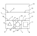
- the sole figure shows a plan view of a flat brittle material, such as chemically tempered glass.
- the brittle material 1 is divided in the embodiment shown by means of defined dividing lines 2 to 5 in different segments. Along the defined parting lines 2 to 5, the brittle material 1 is provided with recesses in that blind holes or through openings are produced in the brittle material 1.
- different geometries 9, 10, 11 are defined in the segments 6, 7, 8 by means of separating lines, along which in turn the brittle material 1 is perforated.
- the dividing lines can be imaginary or desired dividing lines. For example, they may be curves available to a controller so that a laser can be controlled to descend a brittle material along the given curve thereby creating recesses in the brittle material.
- the introduction of the recesses takes place by means of a pulsed laser.
- the brittle material 1 for example, first be wetted at the points 12, 13 with a gaseous medium, which leads to the gaseous medium penetrates into the recesses at these points, resulting in a separation of the segments 14, 15 along the parting line. 2 leads.
- the points 16, 17 are wetted, so that a separation along the dividing line 3 takes place.
- the remaining still contiguous segments 6, 7, 8 can then be placed, for example, then in a liquid bath, so that liquid enters the recesses along the parting lines 4, 5 and the geometries 9, 10, 11 delimiting dividing lines.
- segment 7 that relief tears have been defined by providing further dividing lines 18 to 21, along which the brittle material 1 has also been perforated. In this way, the size of the waste material surrounding the geometry 10 can be defined.
Landscapes
- Physics & Mathematics (AREA)
- Optics & Photonics (AREA)
- Engineering & Computer Science (AREA)
- Chemical & Material Sciences (AREA)
- Organic Chemistry (AREA)
- Materials Engineering (AREA)
- Mechanical Engineering (AREA)
- Toxicology (AREA)
- Health & Medical Sciences (AREA)
- Plasma & Fusion (AREA)
- Thermal Sciences (AREA)
- Life Sciences & Earth Sciences (AREA)
- Chemical Kinetics & Catalysis (AREA)
- General Chemical & Material Sciences (AREA)
- Geochemistry & Mineralogy (AREA)
- Re-Forming, After-Treatment, Cutting And Transporting Of Glass Products (AREA)
- Processing Of Stones Or Stones Resemblance Materials (AREA)
Priority Applications (1)
| Application Number | Priority Date | Filing Date | Title |
|---|---|---|---|
| EP14194510.5A EP3023397A1 (fr) | 2014-11-24 | 2014-11-24 | Procédé de séparation d'une partie d'un matériau cassant |
Applications Claiming Priority (1)
| Application Number | Priority Date | Filing Date | Title |
|---|---|---|---|
| EP14194510.5A EP3023397A1 (fr) | 2014-11-24 | 2014-11-24 | Procédé de séparation d'une partie d'un matériau cassant |
Publications (1)
| Publication Number | Publication Date |
|---|---|
| EP3023397A1 true EP3023397A1 (fr) | 2016-05-25 |
Family
ID=51932281
Family Applications (1)
| Application Number | Title | Priority Date | Filing Date |
|---|---|---|---|
| EP14194510.5A Withdrawn EP3023397A1 (fr) | 2014-11-24 | 2014-11-24 | Procédé de séparation d'une partie d'un matériau cassant |
Country Status (1)
| Country | Link |
|---|---|
| EP (1) | EP3023397A1 (fr) |
Citations (6)
| Publication number | Priority date | Publication date | Assignee | Title |
|---|---|---|---|---|
| JPH0716769A (ja) * | 1993-06-30 | 1995-01-20 | Matsushita Electric Ind Co Ltd | ソーダガラスのレーザ割断工法 |
| EP1518634A1 (fr) * | 2003-09-23 | 2005-03-30 | Advanced Laser Separation International (ALSI) B.V. | Un procédé et un dispositif pour séparer des éléments semi-conducteurs formés dans une pastille semi-conductrice |
| DE102005024563B3 (de) * | 2005-05-28 | 2006-08-03 | Schott Ag | Verfahren zum Trennen von Glas und Verwendung einer dafür geeigneten Flüssigkeit |
| DE102010003314A1 (de) * | 2009-03-31 | 2010-10-07 | Ceramtec Ag | Laserverfahren zur Herstellung einer Kerbstruktur |
| US20110095006A1 (en) * | 2009-10-26 | 2011-04-28 | Toshiba Kikai Kabushiki Kaisha | Laser dicing method and laser dicing apparatus |
| DE102012110971A1 (de) * | 2012-11-14 | 2014-05-15 | Schott Ag | Trennen von transparenten Werkstücken |
-
2014
- 2014-11-24 EP EP14194510.5A patent/EP3023397A1/fr not_active Withdrawn
Patent Citations (6)
| Publication number | Priority date | Publication date | Assignee | Title |
|---|---|---|---|---|
| JPH0716769A (ja) * | 1993-06-30 | 1995-01-20 | Matsushita Electric Ind Co Ltd | ソーダガラスのレーザ割断工法 |
| EP1518634A1 (fr) * | 2003-09-23 | 2005-03-30 | Advanced Laser Separation International (ALSI) B.V. | Un procédé et un dispositif pour séparer des éléments semi-conducteurs formés dans une pastille semi-conductrice |
| DE102005024563B3 (de) * | 2005-05-28 | 2006-08-03 | Schott Ag | Verfahren zum Trennen von Glas und Verwendung einer dafür geeigneten Flüssigkeit |
| DE102010003314A1 (de) * | 2009-03-31 | 2010-10-07 | Ceramtec Ag | Laserverfahren zur Herstellung einer Kerbstruktur |
| US20110095006A1 (en) * | 2009-10-26 | 2011-04-28 | Toshiba Kikai Kabushiki Kaisha | Laser dicing method and laser dicing apparatus |
| DE102012110971A1 (de) * | 2012-11-14 | 2014-05-15 | Schott Ag | Trennen von transparenten Werkstücken |
Similar Documents
| Publication | Publication Date | Title |
|---|---|---|
| DE102013223637B4 (de) | Verfahren zum Behandeln eines lasertransparenten Substrats zum anschließenden Trennen des Substrats | |
| DE102004024643B4 (de) | Werkstückteilungsverfahren unter Verwendung eines Laserstrahls | |
| DE602004003688T2 (de) | Verglasung mit sollbruchlinien | |
| EP2781296A1 (fr) | Dispositif et procédé de découpe de contours à partir de substrats plats au moyen d'un laser | |
| DE102006052824B4 (de) | Verfahren und Vorrichtung beim Laserstrahlschneiden eines metallischen Bauteils | |
| WO2015010862A2 (fr) | Procédé et dispositif permettant de séparer une pièce plate en plusieurs parties de pièce | |
| WO2015018425A1 (fr) | Procédé de traitement d'une pièce en forme de plaque comportant une couche transparente, verré, vitreuse, de céramique et/ou de cristal, dispositif de séparation d'une telle pièce et produit constitué d'une telle pièce | |
| EP2144721B1 (fr) | Procédé de réalisation d'une bande de filons se composant d'une pluralité de filons parallèles entre eux, et bande de filons réalisée selon ce procédé | |
| EP2887475B1 (fr) | Procédé et dispositif de séparation d'un blindage d'un câble coaxial | |
| DE102005047082A1 (de) | Verfahren zur Mikrostrukturierung von Oberflächen eines Werkstücks und seine Verwendung | |
| DE102017106372B4 (de) | Verfahren zur Bearbeitung eines Werkstückes | |
| EP2816017B1 (fr) | Procédé et dispositif de génération d'un trait de rupture sur une ampoule à rompre et ampoule associée | |
| DE102018219465A1 (de) | Verfahren zum Schneiden eines Glaselements und Schneidsystem | |
| DE102016213802A1 (de) | Trennen mit Laserstrahlung | |
| DE102014109792A1 (de) | Verfahren zum Erzeugen eines langzeitstabilen Anrisses auf der Oberfläche eines Elements aus sprödhartem Material | |
| EP3023397A1 (fr) | Procédé de séparation d'une partie d'un matériau cassant | |
| DE19957317C2 (de) | Verfahren zur Anbringung von Sollbruchkanten an einem Werkstück | |
| EP3875436B1 (fr) | Procédé de préparation et/ou de mise en uvre de la séparation d'un élément de substrat et élément de substrat | |
| DE102016120901A1 (de) | Rohrprodukt aus Stahl mit einer Öffnung in seiner Rohrwand, Verwendung eines Rohrproduktes zur Herstellung eines Gasgeneratorgehäuses sowie Gasgeneratorgehäuse | |
| DE102010035673A1 (de) | Glasrohrablängverfahren und -vorrichtung | |
| DE102017112613B4 (de) | Verfahren zum Schwärzen einer Blende, geschwärzte Blende, optisches System und Endoskop mit einer solchen Blende | |
| EP1738622B1 (fr) | Surface utile de plaquette dotee d'une pluralite de porte-circuits et procede pour isoler des porte-circuits d'une surface utile de plaquette | |
| DE10200144B4 (de) | Verfahren und Vorrichtung zum Trennen eines Werkstoffes | |
| DE102008007632A1 (de) | Verfahren zum Laserschneiden eines nichtmetallischen Werkstücks | |
| DE102012211986B3 (de) | Verfahren zum Markieren von Bauteilen eines Triebwerkes für ein Flugzeug |
Legal Events
| Date | Code | Title | Description |
|---|---|---|---|
| AK | Designated contracting states |
Kind code of ref document: A1 Designated state(s): AL AT BE BG CH CY CZ DE DK EE ES FI FR GB GR HR HU IE IS IT LI LT LU LV MC MK MT NL NO PL PT RO RS SE SI SK SM TR |
|
| AX | Request for extension of the european patent |
Extension state: BA ME |
|
| PUAI | Public reference made under article 153(3) epc to a published international application that has entered the european phase |
Free format text: ORIGINAL CODE: 0009012 |
|
| STAA | Information on the status of an ep patent application or granted ep patent |
Free format text: STATUS: THE APPLICATION IS DEEMED TO BE WITHDRAWN |
|
| 18D | Application deemed to be withdrawn |
Effective date: 20161126 |