EP3023224B1 - Sonotrode, schweissvorrichtung mit sonotrode sowie dazugehöriges schweissverfahren - Google Patents
Sonotrode, schweissvorrichtung mit sonotrode sowie dazugehöriges schweissverfahren Download PDFInfo
- Publication number
- EP3023224B1 EP3023224B1 EP15185837.0A EP15185837A EP3023224B1 EP 3023224 B1 EP3023224 B1 EP 3023224B1 EP 15185837 A EP15185837 A EP 15185837A EP 3023224 B1 EP3023224 B1 EP 3023224B1
- Authority
- EP
- European Patent Office
- Prior art keywords
- sonotrode
- workplane
- joining
- welding
- joining part
- Prior art date
- Legal status (The legal status is an assumption and is not a legal conclusion. Google has not performed a legal analysis and makes no representation as to the accuracy of the status listed.)
- Active
Links
Images


Classifications
-
- B—PERFORMING OPERATIONS; TRANSPORTING
- B29—WORKING OF PLASTICS; WORKING OF SUBSTANCES IN A PLASTIC STATE IN GENERAL
- B29C—SHAPING OR JOINING OF PLASTICS; SHAPING OF MATERIAL IN A PLASTIC STATE, NOT OTHERWISE PROVIDED FOR; AFTER-TREATMENT OF THE SHAPED PRODUCTS, e.g. REPAIRING
- B29C65/00—Joining or sealing of preformed parts, e.g. welding of plastics materials; Apparatus therefor
- B29C65/02—Joining or sealing of preformed parts, e.g. welding of plastics materials; Apparatus therefor by heating, with or without pressure
- B29C65/06—Joining or sealing of preformed parts, e.g. welding of plastics materials; Apparatus therefor by heating, with or without pressure using friction, e.g. spin welding
- B29C65/0609—Joining or sealing of preformed parts, e.g. welding of plastics materials; Apparatus therefor by heating, with or without pressure using friction, e.g. spin welding characterised by the movement of the parts to be joined
- B29C65/0618—Linear
-
- B—PERFORMING OPERATIONS; TRANSPORTING
- B29—WORKING OF PLASTICS; WORKING OF SUBSTANCES IN A PLASTIC STATE IN GENERAL
- B29C—SHAPING OR JOINING OF PLASTICS; SHAPING OF MATERIAL IN A PLASTIC STATE, NOT OTHERWISE PROVIDED FOR; AFTER-TREATMENT OF THE SHAPED PRODUCTS, e.g. REPAIRING
- B29C65/00—Joining or sealing of preformed parts, e.g. welding of plastics materials; Apparatus therefor
- B29C65/02—Joining or sealing of preformed parts, e.g. welding of plastics materials; Apparatus therefor by heating, with or without pressure
- B29C65/08—Joining or sealing of preformed parts, e.g. welding of plastics materials; Apparatus therefor by heating, with or without pressure using ultrasonic vibrations
-
- B—PERFORMING OPERATIONS; TRANSPORTING
- B29—WORKING OF PLASTICS; WORKING OF SUBSTANCES IN A PLASTIC STATE IN GENERAL
- B29C—SHAPING OR JOINING OF PLASTICS; SHAPING OF MATERIAL IN A PLASTIC STATE, NOT OTHERWISE PROVIDED FOR; AFTER-TREATMENT OF THE SHAPED PRODUCTS, e.g. REPAIRING
- B29C65/00—Joining or sealing of preformed parts, e.g. welding of plastics materials; Apparatus therefor
- B29C65/02—Joining or sealing of preformed parts, e.g. welding of plastics materials; Apparatus therefor by heating, with or without pressure
- B29C65/08—Joining or sealing of preformed parts, e.g. welding of plastics materials; Apparatus therefor by heating, with or without pressure using ultrasonic vibrations
- B29C65/081—Joining or sealing of preformed parts, e.g. welding of plastics materials; Apparatus therefor by heating, with or without pressure using ultrasonic vibrations having a component of vibration not perpendicular to the welding surface
-
- B—PERFORMING OPERATIONS; TRANSPORTING
- B29—WORKING OF PLASTICS; WORKING OF SUBSTANCES IN A PLASTIC STATE IN GENERAL
- B29C—SHAPING OR JOINING OF PLASTICS; SHAPING OF MATERIAL IN A PLASTIC STATE, NOT OTHERWISE PROVIDED FOR; AFTER-TREATMENT OF THE SHAPED PRODUCTS, e.g. REPAIRING
- B29C66/00—General aspects of processes or apparatus for joining preformed parts
- B29C66/01—General aspects dealing with the joint area or with the area to be joined
- B29C66/05—Particular design of joint configurations
- B29C66/10—Particular design of joint configurations particular design of the joint cross-sections
- B29C66/13—Single flanged joints; Fin-type joints; Single hem joints; Edge joints; Interpenetrating fingered joints; Other specific particular designs of joint cross-sections not provided for in groups B29C66/11 - B29C66/12
- B29C66/135—Single hemmed joints, i.e. one of the parts to be joined being hemmed in the joint area
-
- B—PERFORMING OPERATIONS; TRANSPORTING
- B29—WORKING OF PLASTICS; WORKING OF SUBSTANCES IN A PLASTIC STATE IN GENERAL
- B29C—SHAPING OR JOINING OF PLASTICS; SHAPING OF MATERIAL IN A PLASTIC STATE, NOT OTHERWISE PROVIDED FOR; AFTER-TREATMENT OF THE SHAPED PRODUCTS, e.g. REPAIRING
- B29C66/00—General aspects of processes or apparatus for joining preformed parts
- B29C66/40—General aspects of joining substantially flat articles, e.g. plates, sheets or web-like materials; Making flat seams in tubular or hollow articles; Joining single elements to substantially flat surfaces
- B29C66/41—Joining substantially flat articles ; Making flat seams in tubular or hollow articles
- B29C66/43—Joining a relatively small portion of the surface of said articles
- B29C66/431—Joining the articles to themselves
-
- B—PERFORMING OPERATIONS; TRANSPORTING
- B29—WORKING OF PLASTICS; WORKING OF SUBSTANCES IN A PLASTIC STATE IN GENERAL
- B29C—SHAPING OR JOINING OF PLASTICS; SHAPING OF MATERIAL IN A PLASTIC STATE, NOT OTHERWISE PROVIDED FOR; AFTER-TREATMENT OF THE SHAPED PRODUCTS, e.g. REPAIRING
- B29C66/00—General aspects of processes or apparatus for joining preformed parts
- B29C66/80—General aspects of machine operations or constructions and parts thereof
- B29C66/81—General aspects of the pressing elements, i.e. the elements applying pressure on the parts to be joined in the area to be joined, e.g. the welding jaws or clamps
- B29C66/814—General aspects of the pressing elements, i.e. the elements applying pressure on the parts to be joined in the area to be joined, e.g. the welding jaws or clamps characterised by the design of the pressing elements, e.g. of the welding jaws or clamps
- B29C66/8141—General aspects of the pressing elements, i.e. the elements applying pressure on the parts to be joined in the area to be joined, e.g. the welding jaws or clamps characterised by the design of the pressing elements, e.g. of the welding jaws or clamps characterised by the surface geometry of the part of the pressing elements, e.g. welding jaws or clamps, coming into contact with the parts to be joined
- B29C66/81427—General aspects of the pressing elements, i.e. the elements applying pressure on the parts to be joined in the area to be joined, e.g. the welding jaws or clamps characterised by the design of the pressing elements, e.g. of the welding jaws or clamps characterised by the surface geometry of the part of the pressing elements, e.g. welding jaws or clamps, coming into contact with the parts to be joined comprising a single ridge, e.g. for making a weakening line; comprising a single tooth
-
- B—PERFORMING OPERATIONS; TRANSPORTING
- B29—WORKING OF PLASTICS; WORKING OF SUBSTANCES IN A PLASTIC STATE IN GENERAL
- B29C—SHAPING OR JOINING OF PLASTICS; SHAPING OF MATERIAL IN A PLASTIC STATE, NOT OTHERWISE PROVIDED FOR; AFTER-TREATMENT OF THE SHAPED PRODUCTS, e.g. REPAIRING
- B29C66/00—General aspects of processes or apparatus for joining preformed parts
- B29C66/80—General aspects of machine operations or constructions and parts thereof
- B29C66/81—General aspects of the pressing elements, i.e. the elements applying pressure on the parts to be joined in the area to be joined, e.g. the welding jaws or clamps
- B29C66/814—General aspects of the pressing elements, i.e. the elements applying pressure on the parts to be joined in the area to be joined, e.g. the welding jaws or clamps characterised by the design of the pressing elements, e.g. of the welding jaws or clamps
- B29C66/8141—General aspects of the pressing elements, i.e. the elements applying pressure on the parts to be joined in the area to be joined, e.g. the welding jaws or clamps characterised by the design of the pressing elements, e.g. of the welding jaws or clamps characterised by the surface geometry of the part of the pressing elements, e.g. welding jaws or clamps, coming into contact with the parts to be joined
- B29C66/81433—General aspects of the pressing elements, i.e. the elements applying pressure on the parts to be joined in the area to be joined, e.g. the welding jaws or clamps characterised by the design of the pressing elements, e.g. of the welding jaws or clamps characterised by the surface geometry of the part of the pressing elements, e.g. welding jaws or clamps, coming into contact with the parts to be joined being toothed, i.e. comprising several teeth or pins, or being patterned
-
- B—PERFORMING OPERATIONS; TRANSPORTING
- B29—WORKING OF PLASTICS; WORKING OF SUBSTANCES IN A PLASTIC STATE IN GENERAL
- B29C—SHAPING OR JOINING OF PLASTICS; SHAPING OF MATERIAL IN A PLASTIC STATE, NOT OTHERWISE PROVIDED FOR; AFTER-TREATMENT OF THE SHAPED PRODUCTS, e.g. REPAIRING
- B29C66/00—General aspects of processes or apparatus for joining preformed parts
- B29C66/80—General aspects of machine operations or constructions and parts thereof
- B29C66/81—General aspects of the pressing elements, i.e. the elements applying pressure on the parts to be joined in the area to be joined, e.g. the welding jaws or clamps
- B29C66/814—General aspects of the pressing elements, i.e. the elements applying pressure on the parts to be joined in the area to be joined, e.g. the welding jaws or clamps characterised by the design of the pressing elements, e.g. of the welding jaws or clamps
- B29C66/8145—General aspects of the pressing elements, i.e. the elements applying pressure on the parts to be joined in the area to be joined, e.g. the welding jaws or clamps characterised by the design of the pressing elements, e.g. of the welding jaws or clamps characterised by the constructional aspects of the pressing elements, e.g. of the welding jaws or clamps
- B29C66/81463—General aspects of the pressing elements, i.e. the elements applying pressure on the parts to be joined in the area to be joined, e.g. the welding jaws or clamps characterised by the design of the pressing elements, e.g. of the welding jaws or clamps characterised by the constructional aspects of the pressing elements, e.g. of the welding jaws or clamps comprising a plurality of single pressing elements, e.g. a plurality of sonotrodes, or comprising a plurality of single counter-pressing elements, e.g. a plurality of anvils, said plurality of said single elements being suitable for making a single joint
-
- B—PERFORMING OPERATIONS; TRANSPORTING
- B29—WORKING OF PLASTICS; WORKING OF SUBSTANCES IN A PLASTIC STATE IN GENERAL
- B29C—SHAPING OR JOINING OF PLASTICS; SHAPING OF MATERIAL IN A PLASTIC STATE, NOT OTHERWISE PROVIDED FOR; AFTER-TREATMENT OF THE SHAPED PRODUCTS, e.g. REPAIRING
- B29C66/00—General aspects of processes or apparatus for joining preformed parts
- B29C66/80—General aspects of machine operations or constructions and parts thereof
- B29C66/84—Specific machine types or machines suitable for specific applications
- B29C66/843—Machines for making separate joints at the same time in different planes; Machines for making separate joints at the same time mounted in parallel or in series
-
- B—PERFORMING OPERATIONS; TRANSPORTING
- B29—WORKING OF PLASTICS; WORKING OF SUBSTANCES IN A PLASTIC STATE IN GENERAL
- B29C—SHAPING OR JOINING OF PLASTICS; SHAPING OF MATERIAL IN A PLASTIC STATE, NOT OTHERWISE PROVIDED FOR; AFTER-TREATMENT OF THE SHAPED PRODUCTS, e.g. REPAIRING
- B29C66/00—General aspects of processes or apparatus for joining preformed parts
- B29C66/80—General aspects of machine operations or constructions and parts thereof
- B29C66/84—Specific machine types or machines suitable for specific applications
- B29C66/851—Bag or container making machines
- B29C66/8511—Bag making machines
-
- B—PERFORMING OPERATIONS; TRANSPORTING
- B65—CONVEYING; PACKING; STORING; HANDLING THIN OR FILAMENTARY MATERIAL
- B65B—MACHINES, APPARATUS OR DEVICES FOR, OR METHODS OF, PACKAGING ARTICLES OR MATERIALS; UNPACKING
- B65B51/00—Devices for, or methods of, sealing or securing package folds or closures; Devices for gathering or twisting wrappers, or necks of bags
- B65B51/10—Applying or generating heat or pressure or combinations thereof
- B65B51/22—Applying or generating heat or pressure or combinations thereof by friction or ultrasonic or high-frequency electrical means
- B65B51/225—Applying or generating heat or pressure or combinations thereof by friction or ultrasonic or high-frequency electrical means by ultrasonic welding
-
- B—PERFORMING OPERATIONS; TRANSPORTING
- B65—CONVEYING; PACKING; STORING; HANDLING THIN OR FILAMENTARY MATERIAL
- B65B—MACHINES, APPARATUS OR DEVICES FOR, OR METHODS OF, PACKAGING ARTICLES OR MATERIALS; UNPACKING
- B65B51/00—Devices for, or methods of, sealing or securing package folds or closures; Devices for gathering or twisting wrappers, or necks of bags
- B65B51/10—Applying or generating heat or pressure or combinations thereof
- B65B51/26—Devices specially adapted for producing transverse or longitudinal seams in webs or tubes
- B65B51/30—Devices, e.g. jaws, for applying pressure and heat, e.g. for subdividing filled tubes
- B65B51/303—Devices, e.g. jaws, for applying pressure and heat, e.g. for subdividing filled tubes reciprocating along only one axis
-
- B—PERFORMING OPERATIONS; TRANSPORTING
- B65—CONVEYING; PACKING; STORING; HANDLING THIN OR FILAMENTARY MATERIAL
- B65B—MACHINES, APPARATUS OR DEVICES FOR, OR METHODS OF, PACKAGING ARTICLES OR MATERIALS; UNPACKING
- B65B9/00—Enclosing successive articles, or quantities of material, e.g. liquids or semiliquids, in flat, folded, or tubular webs of flexible sheet material; Subdividing filled flexible tubes to form packages
-
- B—PERFORMING OPERATIONS; TRANSPORTING
- B29—WORKING OF PLASTICS; WORKING OF SUBSTANCES IN A PLASTIC STATE IN GENERAL
- B29C—SHAPING OR JOINING OF PLASTICS; SHAPING OF MATERIAL IN A PLASTIC STATE, NOT OTHERWISE PROVIDED FOR; AFTER-TREATMENT OF THE SHAPED PRODUCTS, e.g. REPAIRING
- B29C66/00—General aspects of processes or apparatus for joining preformed parts
- B29C66/70—General aspects of processes or apparatus for joining preformed parts characterised by the composition, physical properties or the structure of the material of the parts to be joined; Joining with non-plastics material
- B29C66/71—General aspects of processes or apparatus for joining preformed parts characterised by the composition, physical properties or the structure of the material of the parts to be joined; Joining with non-plastics material characterised by the composition of the plastics material of the parts to be joined
-
- B—PERFORMING OPERATIONS; TRANSPORTING
- B29—WORKING OF PLASTICS; WORKING OF SUBSTANCES IN A PLASTIC STATE IN GENERAL
- B29C—SHAPING OR JOINING OF PLASTICS; SHAPING OF MATERIAL IN A PLASTIC STATE, NOT OTHERWISE PROVIDED FOR; AFTER-TREATMENT OF THE SHAPED PRODUCTS, e.g. REPAIRING
- B29C66/00—General aspects of processes or apparatus for joining preformed parts
- B29C66/70—General aspects of processes or apparatus for joining preformed parts characterised by the composition, physical properties or the structure of the material of the parts to be joined; Joining with non-plastics material
- B29C66/71—General aspects of processes or apparatus for joining preformed parts characterised by the composition, physical properties or the structure of the material of the parts to be joined; Joining with non-plastics material characterised by the composition of the plastics material of the parts to be joined
- B29C66/712—General aspects of processes or apparatus for joining preformed parts characterised by the composition, physical properties or the structure of the material of the parts to be joined; Joining with non-plastics material characterised by the composition of the plastics material of the parts to be joined the composition of one of the parts to be joined being different from the composition of the other part
-
- B—PERFORMING OPERATIONS; TRANSPORTING
- B29—WORKING OF PLASTICS; WORKING OF SUBSTANCES IN A PLASTIC STATE IN GENERAL
- B29C—SHAPING OR JOINING OF PLASTICS; SHAPING OF MATERIAL IN A PLASTIC STATE, NOT OTHERWISE PROVIDED FOR; AFTER-TREATMENT OF THE SHAPED PRODUCTS, e.g. REPAIRING
- B29C66/00—General aspects of processes or apparatus for joining preformed parts
- B29C66/90—Measuring or controlling the joining process
- B29C66/95—Measuring or controlling the joining process by measuring or controlling specific variables not covered by groups B29C66/91 - B29C66/94
- B29C66/951—Measuring or controlling the joining process by measuring or controlling specific variables not covered by groups B29C66/91 - B29C66/94 by measuring or controlling the vibration frequency and/or the vibration amplitude of vibrating joining tools, e.g. of ultrasonic welding tools
- B29C66/9513—Measuring or controlling the joining process by measuring or controlling specific variables not covered by groups B29C66/91 - B29C66/94 by measuring or controlling the vibration frequency and/or the vibration amplitude of vibrating joining tools, e.g. of ultrasonic welding tools characterised by specific vibration frequency values or ranges
-
- B—PERFORMING OPERATIONS; TRANSPORTING
- B29—WORKING OF PLASTICS; WORKING OF SUBSTANCES IN A PLASTIC STATE IN GENERAL
- B29L—INDEXING SCHEME ASSOCIATED WITH SUBCLASS B29C, RELATING TO PARTICULAR ARTICLES
- B29L2031/00—Other particular articles
- B29L2031/712—Containers; Packaging elements or accessories, Packages
- B29L2031/7128—Bags, sacks, sachets
Definitions
- the present invention relates to a sonotrode for friction welding of at least two joining parts, which at least partially consist of weldable plastic, a corresponding welding device and a corresponding welding method.
- a plastic bag to be filled in raw form must be provided.
- the raw form of the plastic bag has an opening through which the raw form with product is befiillbar.
- this opening is formed between opposite ends of a film or between two separate films.
- hot stamping a subsequent closing of the opening by means of hot stamping done.
- the ultrasonic waves are introduced perpendicularly from the sonotrode into the surfaces of the films to be welded together.
- a known procedure is, for example, the processing of tubular films. These are filled from above and closed at the top after filling. This procedure is therefore also called “vertical form and fill”.
- a disadvantage of these known devices are the low clock rate and a high space requirement. In particular, in ultrasonic welding often only an ultrasonic sonotrode can be used due to the available space, resulting in a low throughput rate for the plastic bag.
- a method and apparatus for high frequency bonding or sealing of materials are known in the art US 3,376,179 described.
- a mechanical high-frequency vibration is applied directly to the surfaces between two surfaces of the material.
- the vibrations have a major amount of movement in the direction parallel to the surfaces so as to perform a rubbing motion thereon that generates heat and softens the materials.
- the materials are pressed together until the softened material solidifies again.
- An ultrasonic welder is in the DE 88 11 803 U1 described.
- a central channel of a wedge-shaped tool of the ultrasonic welding device is at least 0.3 mm deeper than the deepest of the roughening.
- a transverse groove in the tool is interrupted by the central channel.
- US 4,713,131 describes an apparatus and method for ultrasonically bonding material layers of thermoplastic material.
- the apparatus comprises a support frame, a pair of connecting rollers forming a nip having an axis parallel to the roll axis, a motor for driving at least one of the rollers, a sonotrode with a tip, and an ultrasonic transducer to move the sonotrode and the tip in the direction of the longitudinal axis of the Vibrate sonotrode.
- the sonotrode is arranged to vibrate transverse to the axis of the gap so that adjacent edges of the layers can be moved through the gap. The edges are then evenly melted on each side of the tip and pressed together in the gap and welded.
- the apparatus includes a sonotrode and anvil which provide contact surfaces in contact with the elements to be welded. Each contact surface is provided with a plurality of grooves to provide a plurality of protrusions.
- US 2004/0103910 A1 describes an applicator for spare hair strands that works with ultrasonic vibrations.
- a sonotrode for friction welding at least two joining parts at least partially made of weldable plastic, comprising a) a base body having a longitudinal axis lying in a working plane of the sonotrode, the sonotrode being deflectable in operation within said working plane, b a first working surface is arranged laterally relative to the longitudinal axis on the sonotrode, so that joining energy can be introduced laterally into a first joining zone, and c) a second working surface is arranged laterally relative to the longitudinal axis on the sonotrode, so that joining energy laterally into a second joining In operation, the first working surface in a first plane parallel to the working plane and the second working surface move in a second plane parallel to the working plane.
- the objective technical objective of the present invention is therefore to provide a welding device which, compared with known welding devices, requires less space at a simultaneously higher cycle rate.
- the sonotrode or friction welding sonotrode according to the invention for friction welding of at least two joining parts comprises a base body having a longitudinal axis which lies in a working plane of the sonotrode, wherein the sonotrode is deflectable in operation within this working plane, wherein a first working surface is arranged laterally relative to the longitudinal axis on the sonotrode, so that joining energy can be introduced laterally into a first joining zone between a first and a second joining part, and a second working surface is arranged laterally relative to the longitudinal axis on the sonotrode, so that joining energy can be introduced laterally into a second joining zone between a third and a fourth joining part, wherein in operation the first working surface moves in a first plane parallel to the working plane and the
- the above preferred sonotrode according to the invention will now be explained in more detail with reference to an operation of a friction welding device during a corresponding friction welding process, reference being made by way of example to the production of a plastic bag.
- the welding device comprises the preferred sonotrode according to the invention and a first anvil having a first pressure surface and a second anvil having a second pressure surface.
- the main body of the sonotrode is designed, for example, essentially cuboid.
- the longitudinal axis extends through a first end and a second end of the base body, wherein the first end is arranged in the operation of the sonotrode on the welding device.
- the first and second work surfaces are arranged adjacent to the second end.
- the welding method initially comprises the step of providing a first and a second joining part and a third and a fourth joining part, which at least partially consist of a weldable plastic.
- a first and a second joining part and a third and a fourth joining part which at least partially consist of a weldable plastic.
- four individual films are used as an example.
- an overlapping foil would be conceivable as the first and second joining part.
- the two joining parts are arranged between the first lateral working face of the sonotrode and the first pressing face of the first anvil. Then, the first anvil is moved with the first pressure surface in the direction of the first working surface of the sonotrode.
- the first joining part comes into abutment against the first working surface of the sonotrode and the first pressure surface of the first anvil presses or presses the first and the second joining part against the first working surface of the sonotrode.
- the sonotrode While the first pressure surface of the first anvil presses the first and the second joining part against the first working surface of the sonotrode, the sonotrode is excited to vibrate in its working plane, preferably along its longitudinal axis. As a result, the first work surface performs a movement in the first plane parallel to the working plane of the sonotrode.
- the second work surface performs in the same way a movement in the second plane parallel to the working plane of the sonotrode. In an exclusive excitation of the sonotrode along the longitudinal axis, the respective working surface thus moves in the respective plane along a straight line, which is arranged in particular parallel to the longitudinal axis.
- a movement of the two work surfaces along a curvilinear path in the respective plane can be realized. With this movement, too, a preferred welding of the first and the second joining part takes place together and preferably of the third and the fourth joining part, as explained in more detail below.
- a third and a fourth joining part can be welded to the sonotrode according to the invention.
- the third and the fourth joining part between the second lateral working surface of the sonotrode and the second pressure surface of the second anvil are arranged.
- the second anvil is moved with the second pressure surface in the direction of the second working surface of the sonotrode.
- the third joining part comes into contact with the second working surface of the sonotrode and the second pressure surface of the second anvil presses or presses the third and the fourth joining part against the second working surface of the sonotrode.
- the sonotrode While the second pressure surface of the second anvil pushes the third and the fourth joining part against the second working surface of the sonotrode, the sonotrode is excited to vibrate along its longitudinal axis and / or transversely to its longitudinal axis. In this way, a welding of the third and the fourth joining part takes place together.
- the first and the second working surface of the sonotrode are present on a side surface of the sonotrode, and are therefore present laterally relative to the longitudinal axis along which the sonotrode oscillates during operation.
- the work surfaces are not at an axial end of the sonotrode, as is common in the prior art, but on a side surface.
- the first and the second working surface are also arranged on the sides of the basic body which extend parallel to the direction of vibration. This will be clarified later with reference to the drawings.
- the first and the second working surface are therefore arranged on opposite sides of the sonotrode.
- the amplitude of the sonotrode, the pressure exerted on the parts to be welded, and the joining time are varied as parameters for setting the welding process.
- no variation of the oscillation frequency of the sonotrode takes place. This means that in a working process of the sonotrode this is regulated by the generator to the same frequency or to the same previously selected frequency or operating frequency.
- the first working surface of the sonotrode and the first pressure surface of the first anvil are moved apart so that the welded together first and second joining parts are removable from the welding device.
- the second working surface of the sonotrode and the second pressure surface of the second anvil are moved apart so that the welded together third and fourth joining parts can be removed from the welding device.
- the first or the second working surface of the sonotrode has a structure, in particular in the form of a plurality of elevations.
- a joining part which is pressed against the sonotrode during operation is carried along by the sonotrode and caused to vibrate.
- the structure of the sonotrode can therefore also be referred to as a driving structure.
- the driving structure digs into the adjacent joining part, so that the adjacent joining part performs substantially the same movements as the sonotrode. In this way, a connection between two parts to be joined by means of friction welding can be effectively realized.
- a welding device or friction welding device for friction welding of at least two joining parts, which at least partially consist of weldable plastic, comprises a sonotrode according to the invention with a first working surface, which is arranged laterally relative to a longitudinal axis of a base body, and with a second working surface, based on the longitudinal axis of the main body is also arranged laterally, and a first anvil with a first pressure surface and a second anvil with a second pressure surface, wherein in operation of the welding device, a first and a second joining part by means of the first pressure surface of the first anvil and the first lateral working surface with each other are weldable and a third and a fourth adherend are welded together by means of the second pressure surface of the second anvil and the second lateral working surface.
- the first pressure surface of the first anvil and / or the second pressure surface of the second anvil has a structure, in particular in the form of a plurality of elevations. Due to the plurality of elevations, a respective joining part can be held or clamped particularly securely between the respective printing surface and the corresponding working surface.
- the respective pressure surface of the anvil engages by means of this structure in the respective joining part adjacent to the corresponding pressure surface. In this way, an effective retention of the corresponding joining part can be realized.
- the structure of the respective pressure surface of the corresponding anvil can therefore also be referred to as a retaining structure.
- This embodiment is particularly preferred in combination with the sonotrode, whose respective working surface has a structure for taking along a fitting part lying thereon.
- the inventive welding method or friction welding method with a welding device comprises the steps of providing a first and a second joining part and a third and a fourth joining part, which at least partially made of weldable plastic, arranging the first and the second joining part between a laterally to the vibration direction of a Sonotrode arranged first working surface of the sonotrode and a first pressure surface of a first anvil, arranging the third and fourth joining part between a laterally arranged to the vibration direction of a sonotrode second working surface of the sonotrode and a second pressure surface of a second anvil, exciting the sonotrode to vibrate along and / or transverse to a longitudinal axis of a main body of the sonotrode, whereby joining energy can be introduced laterally into a first and / or second joining zone and a welded joint between the first and the z forms far joining part and / or between the third and the fourth joining part, and moving apart of the first working surface of the sonotrode and the first pressure surface of the first anvil and
- a vibration of the sonotrode takes place in the ultrasonic range, preferably between 20 and 40 kHz, particularly preferably between 20 and 30 kHz. Due to the specified frequency ranges, the sonotrode operates in the ultrasound range and a fast, efficient and economical connection of the at least two joining parts with each other is ensured.
- the welding of the first and the second joining part as well as the third and the fourth joining part takes place simultaneously. In this way, the method is particularly efficient, since two products, such as plastic bags, can be produced simultaneously.
- the embodiment of the welding device or friction welding device according to the invention will be explained with reference to the welding of a plastic bag.
- the plastic bags to be welded consist for example of two films which preferably comprise thermoplastic material as material, in particular polyethylene (PE), polypropylene (PP) or polyethylene terephthalate (PET) (see above).
- PE polyethylene
- PP polypropylene
- PET polyethylene terephthalate
- all foils, and thus all four joining parts comprise the same material.
- the four joining parts may also comprise different materials.
- the plastic bags are used, for example, for storing and transporting flowable products, such as soap, drinks and the like. Referring to the FIGS. 1 to 3 First, the sonotrode 1 is explained.
- the sonotrode 1 comprises a main body 10 with a substantially parallelepiped basic shape.
- the main body has a longitudinal axis L1 and a first 12 and a second working surface 14.
- a first end along the longitudinal axis L1 is later engaged in operation with a welding device while the opposite end is referred to as a second end.
- the base body 10 is viewed from the second end, it preferably has a rectangular outline.
- the sonotrode 1 can be deflected during later operation in a welding device 3, which will be explained in detail later.
- Adjacent to the second end, the first 12 and the second working surface 14 are arranged on opposite sides of the base body 10. In particular, the first 12 and the second working surface 14 are arranged on the long sides of the rectangular plan.
- the first working surface 12 has a structure, which preferably consists of a plurality of elevations.
- the second work surface 14 according to the invention has no structure.
- the elevations provide an enlargement of the surface, with which the first working surface 12 later bears against the parts to be welded together.
- the joining parts are better fastened between the working surface 12 and a pressure surface, which will be explained below with reference to the welding device.
- only one of the work surfaces 12, 14 has a structure.
- the welding apparatus 3 includes those with reference to FIGS FIGS.
- FIG. 4 shown two deflected films, which are arranged between the first working surface 12 and the first pressure surface 22 and between the second working surface 14 and the second pressure surface 26.
- the first deflected film represents a first 30 and a second adherend 32
- the second film represents a third 34 and a fourth adherend 36.
- the respective working surface 12, 14 of the sonotrode 1 are in engagement with the respective pressure surface 22, 26 of the respective anvil 20, 24.
- first 30 and the second joining part 32 are arranged, while between the second working surface 14 and the second pressure surface 26, the third 34 and the fourth joining part 36 are arranged.
- first 22 and the second pressure surface 26 have a structure, in particular in the form of a plurality of elevations.
- only one of the two pressure surfaces 22, 26 may have a structure or none of the pressure surfaces 22, 26 has a structure.
- the adhering thereto fitting is set in vibration. Due to the structure of the first 22 and / or the second pressure surface 26, which is also referred to as a holding structure, the adhering thereto fitting is preferably retained in its position relative to a movement of the sonotrode 1.
- a friction welding connection between two joining parts 30, 32 and / or 34, 36 can therefore be effectively realized by means of the respective structures, irrespective of the order of arrangement of the joining parts 30, 32 and 34, 36 between the respective anvil 20, 24 and the working surface 12, 14 of the sonotrode 1.
- a vibration of the sonotrode 1 for welding the first 30 and the second joining part 32 together and the third 34 and the fourth joining part 36 takes place according to a preferred embodiment along the longitudinal axis L1 of the sonotrode 1.
- the movement of the two working surfaces within the respective plane takes place parallel to the working plane as a function of the configuration of the sonotrode in another movement pattern, such as along a curvilinear path.
- the vibration is not only up and down, but also forward and backward.
- other processes are possible. For example, alternately a plastic bag between the first working surface 12 and the first Pressure surface 22 and between the second working surface 14 and second pressure surface 26 are produced.
- a first step A the first 30, the second 32, the third 34 and the fourth joining part 36 are provided. Subsequently, the first 30 and the second joining part 32 in step B between the first work surface 12 and the first pressure surface 22 are arranged. At the same time, after or before, the third 34 and the fourth joining part 36 are disposed between the second work surface 14 and the second pressure surface 26 in step C.
- the respective pressure surfaces 22, 26 are moved in the direction of the respective work surfaces 12, 14, so that the corresponding joining parts 30 and 32 and 34 and 36 are clamped.
- the sonotrode 1 is excited in step D to oscillate along and / or transversely to the longitudinal axis L1 of the base body 10. In this way, joining energy is introduced laterally into a first and second joining zone and a welded connection is formed between the first 30 and the second joining part 32 and between the third 34 and the fourth joining part 36.
- a vibration of the sonotrode 1 depends in particular on the material to be processed. For example, the vibration may be in the range of 20 to 40 kHz, preferably 20 to 30 kHz.
- a variation of the welding parameters of the welding device 3 preferably takes place only insofar as the amplitude, the welding duration or the pinching force are varied. In particular, a variation of the working frequency does not occur.
- step E the first working surface 12 of the sonotrode 1 and the first pressure surface 22 of the first anvil 20 are moved apart. Likewise, the second working surface 14 of the sonotrode 1 and the second pressure surface 26 of the second anvil 24 are moved apart. In this way, the first 30 and second joining parts 32 welded together and the third 34 and fourth joining parts 36 can be removed from the welding device 3.
- step D follows only with the welding of the first 30 and second adherends 32.
- Step C is performed concurrently with this step D.
- step E becomes the first 30 and the second joining part 32 are performed while performing step D for the third 34 and the fourth joining part 36.
- the sonotrode 1 and the first 20 and the second anvil 24 are reciprocated between a first and a second position during steps B to E. In this way, a further transport of the plastic bag to be produced also takes place in the welding device 3, so that the process sequence is further optimized.
Landscapes
- Engineering & Computer Science (AREA)
- Mechanical Engineering (AREA)
- Lining Or Joining Of Plastics Or The Like (AREA)
- Pressure Welding/Diffusion-Bonding (AREA)
Description
- Die vorliegende Erfindung betrifft eine Sonotrode zum Reibschweißen von mindestens zwei Fügeteilen, die zumindest teilweise aus verschweißbarem Kunststoff bestehen, eine entsprechende Schweißvorrichtung sowie ein entsprechendes Schweißverfahren. Bei der Herstellung von Kunststoffbeuteln für beispielsweise Seife, Getränke oder ähnliche Produkte, muss zunächst ein zu befüllender Kunststoffbeutel in Rohform bereitgestellt werden. Die Rohform des Kunststoffbeutels verfügt über eine Öffnung, durch die die Rohform mit Produkt befiillbar ist. Üblicherweise ist diese Öffnung zwischen sich gegenüberliegenden Enden einer Folie oder zwischen zwei separaten Folien gebildet.
Zur Herstellung der Rohform werden entweder die zwei Folien oder die eine übereinanderliegende Folie mittels Heißstempeln an den Rändern miteinander verbunden. Ebenso kann ein späteres Verschließen der Öffnung mittels Heißstempeln erfolgen. Alternativ zum Heißstempeln ist bekannt, die Folien mittels Ultraschall miteinander zu verschweißen. Die Ultraschallwellen werden hierbei senkrecht von der Sonotrode in die Oberflächen der miteinander zu verschweißenden Folien eingeleitet. Eine bekannte Vorgehensweise ist beispielsweise die Verarbeitung von Schlauchfolien. Diese werden von oben befüllt und nach erfolgter Füllung oben verschlossen. Diese Vorgehensweise wird daher auch als "vertikal form and fill" bezeichnet.
Ein Nachteil dieser bekannten Vorrichtungen sind die geringe Taktrate sowie ein hoher Platzbedarf. Insbesondere beim Ultraschallschweißen kann aufgrund des zur Verfügung stehenden Raums oft nur eine Ultraschallsonotrode eingesetzt werden, so dass daraus eine geringe Durchsatzrate für die Kunststoffbeutel resultiert. - Ein Verfahren und eine Vorrichtung zum Hochfrequenzverbinden oder Abdichten von Materialien sind in
US 3,376,179 beschrieben. Hierbei wird zwischen zwei Oberflächen des Materials eine mechanische Hochfrequenzvibration direkt auf die Oberflächen angewendet. Die Vibrationen weisen einen Hauptbewegungsanteil in Richtung parallel zu den Oberflächen auf, um so eine Reibbewegung darauf auszuführen, die Wärme erzeugt und die Materialien erweicht. Anschließend werden die Materialien aneinander gepresst, bis das erweichte Material sich erneut verfestigt.
Ein Ultraschallschweißgerät ist in derDE 88 11 803 U1 beschrieben. Dabei ist ein Mittelkanal eines keilförmigen Werkzeugs des Ultraschallschweißgeräts um mindestens 0,3 mm tiefer als das Tiefste der Aufrauung. Weiterhin ist eine Querrille im Werkzeug durch den Mittelkanal unterbrochen.
US 4,713,131 beschreibt eine Vorrichtung und ein Verfahren zum Ultraschallverbinden von Materiallagen aus thermoplastischem Material. Die Vorrichtung umfasst einen Tragrahmen, ein Paar Verbindungswalzen, die einen Spalt mit einer Achse parallel zur Walzenachse bilden, einen Motor, um mindestens eine der Walzen anzutreiben, eine Sonotrode mit Spitze sowie einen Ultraschallwandler, um die Sonotrode und die Spitze in Richtung der Längsachse der Sonotrode schwingen zu lassen. Die Sonotrode ist so angeordnet, dass sie quer zur Achse des Spalts schwingt, sodass benachbarte Ränder der Lagen durch den Spalt bewegt werden können. Die Ränder werden dann auf jeder Seite der Spitze gleichmäßig geschmolzen und im Spalt zusammengepresst und verschweißt.
Eine weitere Ulraschallschweißvorrichtung ist inEP 0 242 480 A2 beschrieben. Die Vorrichtung umfasst eine Sonotrode und einen Amboss, die Kontaktoberflächen in Kontakt mit den zu verschweißenden Elementen bereitstellen. Jede Kontaktoberfläche ist bereitgestellt mit einer Mehrzahl von Rillen, um eine Mehrzahl von Vorsprüngen bereitzustellen.
US 2004/0103910 A1 beschreibt einen Applikator für Ersatzhaarstränge, der mit Ultraschallschwingungen arbeitet. - Ein Stapelartikel mit textilem Rücken sowie ein Verfahren zum Herstellen davon mittels Ultraschallschweißen sind in
US 2004/0076790 A1 beschrieben. Schließlich beschreibtGB 2 023 065 A GB 2 023 065 A - Die objektive technische Aufgabe der vorliegenden Erfindung ist daher die Bereitstellung einer Schweißvorrichtung, die im Vergleich zu bekannten Schweißvorrichtungen weniger Platzbedarf bei einer gleichzeitig höheren Takt- bzw. Ausstoßrate aufweist.
- Die obige objektive technische Aufgabe wird gelöst durch eine Sonotrode gemäß dem unabhängigen Patentanspruch 1, eine Schweißvorrichtung gemäß dem Patentanspruch 3 sowie ein Schweißverfahren gemäß dem unabhängigen Patentanspruch 5. Vorteilhafte Ausführungsformen ergeben sich aus der nachfolgenden Beschreibung, den Zeichnungen sowie den abhängigen Patentansprüchen.
Die erfindungsgemäße Sonotrode bzw. Reibschweißsonotrode zum Reibschweißen von mindestens zwei Fügeteilen, die zumindest teilweise aus verschweißbarem Kunststoff bestehen, umfasst einen Grundkörper, der eine Längsachse aufweist, die in einer Arbeitsebene der Sonotrode liegt, wobei die Sonotrode im Betrieb innerhalb dieser Arbeitsebene auslenkbar ist, wobei eine erste Arbeitsfläche bezogen auf die Längsachse lateral an der Sonotrode angeordnet ist, so dass Fügeenergie lateral in eine erste Fügezone zwischen einem ersten und einem zweiten Fügeteil einleitbar ist, und eine zweite Arbeitsfläche bezogen auf die Längsachse lateral an der Sonotrode angeordnet ist, so dass Fügeenergie lateral in eine zweite Fügezone zwischen einem dritten und einem vierten Fügeteil einleitbar ist, wobei sich im Betrieb die erste Arbeitsfläche in einer ersten Ebene parallel zur Arbeitsebene und die zweite Arbeitsfläche in einer zweiten Ebene parallel zur Arbeitsebene bewegen.
Die obige erfindungsgemäß bevorzugte Sonotrode wird nun näher erläutert anhand einer Funktionsweise einer Reibschweißvorrichtung während eines entsprechenden Reibschweißverfahrens, wobei beispielhaft auf die Herstellung eines Kunststoffbeutels Bezug genommen wird. Die Schweißvorrichtung umfasst die erfindungsgemäß bevorzugte Sonotrode sowie einen ersten Amboss mit einer ersten Druckfläche und einen zweiten Amboss mit einer zweiten Druckfläche. Der Grundkörper der Sonotrode ist beispielhaft im Wesentlichen quaderförmig ausgestaltet. Die Längsachse verläuft durch ein erstes Ende und ein zweites Ende des Grundkörpers, wobei das erste Ende im Betrieb der Sonotrode an der Schweißvorrichtung angeordnet ist. Vorzugsweise benachbart dem zweiten Ende sind die erste und die zweite Arbeitsfläche angeordnet.
Das Schweißverfahren umfasst zunächst den Schritt des Bereitstellens eines ersten und eines zweiten Fügeteils sowie eines dritten und eines vierten Fügeteils, die zumindest teilweise aus einem verschweißbaren Kunststoff bestehen. Zur besseren Verständlichkeit wird beispielhaft von vier einzelnen Folien ausgegangen. Alternativ wäre eine sich überlappend gelegte Folie als erstes und zweites Fügeteil denkbar. Dasselbe gilt für das dritte und vierte Fügeteil, wobei auch entsprechende Kombinationen möglich sind. - Zum Verschweißen des ersten und des zweiten Fügeteils miteinander werden die beiden Fügeteile zwischen der ersten lateralen Arbeitsfläche der Sonotrode und der ersten Druckfläche des ersten Ambosses angeordnet. Dann wird der erste Amboss mit der ersten Druckfläche in Richtung der ersten Arbeitsfläche der Sonotrode bewegt. Somit gelangt beispielsweise das erste Fügeteil in Anlage an der ersten Arbeitsfläche der Sonotrode und die erste Druckfläche des ersten Ambosses drückt bzw. presst das erste und das zweite Fügeteil gegen die erste Arbeitsfläche der Sonotrode.
- Während die erste Druckfläche des ersten Ambosses das erste und das zweite Fügeteil gegen die erste Arbeitsfläche der Sonotrode drückt, wird die Sonotrode zum Schwingen in ihrer Arbeitsebene, vorzugsweise entlang ihrer Längsachse, angeregt. Dadurch führt die erste Arbeitsfläche eine Bewegung in der ersten Ebene parallel zur Arbeitsebene der Sonotrode aus. Die zweite Arbeitsfläche führt in gleicher Weise eine Bewegung in der zweiten Ebene parallel zur Arbeitsebene der Sonotrode aus. Bei einer ausschließlichen Anregung der Sonotrode entlang der Längsachse bewegt sich die jeweilige Arbeitsfläche somit in der jeweiligen Ebene entlang einer Geraden, die insbesondere parallel zur Längsachse angeordnet ist. In Abhängigkeit von der Ausgestaltung der Sonotrode ist gemäß einer weiteren bevorzugten Ausführungsform der vorliegenden Erfindung eine Bewegung der beiden Arbeitsflächen entlang einer krummlinigen Bahn in der jeweiligen Ebene realisierbar. Mit dieser Bewegung erfolgt ebenfalls ein bevorzugtes Verschweißen des ersten und des zweiten Fügeteils miteinander sowie bevorzugt des dritten und des vierten Fügeteils, wie unten näher erläutert ist.
- Gleichzeitig oder im Wechsel mit den obigen Schritten zum Verschweißen des ersten und des zweiten Fügeteils miteinander können mit der erfindungsgemäßen Sonotrode ein drittes und ein viertes Fügeteil verschweißt werden. Hierzu werden das dritte und das vierte Fügeteil zwischen der zweiten lateralen Arbeitsfläche der Sonotrode und der zweiten Druckfläche des zweiten Ambosses angeordnet. Dann wird der zweite Amboss mit der zweiten Druckfläche in Richtung der zweiten Arbeitsfläche der Sonotrode bewegt. Somit gelangt beispielsweise das dritte Fügeteil in Anlage mit der zweiten Arbeitsfläche der Sonotrode und die zweite Druckfläche des zweiten Ambosses drückt bzw. presst das dritte und das vierte Fügeteil gegen die zweite Arbeitsfläche der Sonotrode.
- Während die zweite Druckfläche des zweiten Ambosses das dritte und das vierte Fügeteil gegen die zweite Arbeitsfläche der Sonotrode drückt, wird die Sonotrode zum Schwingen entlang ihrer Längsachse und/oder quer zu ihrer Längsachse angeregt. Auf diese Weise erfolgt ein Verschweißen des dritten und des vierten Fügeteils miteinander.
- Wie oben erwähnt, liegen die erste und die zweite Arbeitsfläche der Sonotrode erfindungsgemäß an einer Seitenfläche der Sonotrode vor, sind also bezogen auf die Längsachse, entlang der die Sonotrode im Betrieb schwingt, lateral vorhanden. Somit befinden sich die Arbeitsflächen nicht an einem axialen Ende der Sonotrode, wie es im Stand der Technik üblich ist, sondern an einer Seitenfläche. Hierbei ist zu beachten, dass bei einer Schwingung der Sonotrode quer zur Längsachse des Grundkörpers die erste und die zweite Arbeitsfläche ebenfalls an den Seiten des Grundkröpers angeordnet sind, die parallel zur Schwingungsrichtung verlaufen. Dies wird später unter Bezugnahme auf die Zeichnungen verdeutlicht. Vorzugsweise sind die ersten und die zweite Arbeitsfläche daher an gegenüberliegenden Seiten der Sonotrode angeordnet.
- Auf diese Weise werden daher auch die Probleme beim axialen Einleiten von Fügeenergie in das Material vermieden, wie sie insbesondere beim Fügen von Kunststoffen mittels Ultraschall vorkommen. Probleme treten hierbei insbesondere beim axialen Ultraschallschweißen von Kunststoffteilen mit nicht ebenen Oberflächen auf. Üblicherweise liegt am mit den zu verschweißenden Bauteilen in Kontakt kommenden axialen Ende der Sonotrode eine maximale Schwingungsamplitude, also ein Bauch des Schwingungssignals der Sonotrode, vor. Weisen die zu verschweißenden Bauteile nun keine gleichmäßige Oberfläche, beispielsweise aufgrund von Ungenauigkeiten oder Schwankungen bei der Herstellung der Bauteile, auf, dann kann es zu lokalen Über- und/oder Unterschweißungen durch Überhitzung oder mangelnde Erwärmung kommen. Insbesondere beim Verschweißen von Kunststoffbeuteln kann es somit zu einer Überhitzung und damit zu einer irreparablen Beschädigung des Kunststoffbeutels kommen. Dies ist jedoch nachteilig für die Schweißverbindung insgesamt, weil es die Fügeteile nicht verlässlich verbindet oder die Fügeteile beim Verbinden beschädigt.
- Im Gegensatz dazu wird durch die erfindungsgemäß bevorzugte Reibschweißsonotrode, da die Arbeitsfläche der Sonotrode an einer Seitenfläche vorhanden ist, Fügeenergie lateral in die erste und/oder die zweite Fügezone eingeleitet. Auf diese Weise bildet sich eine Schweißverbindung ohne lokale Über- oder Unterschweißungen zwischen dem ersten und dem zweiten Fügeteil sowie dem dritten und dem vierten Fügeteil aus.
- Als Parameter zur Einstellung des Schweißverfahrens werden insbesondere die Amplitude der Sonotrode, der auf die zu verschweißenden Fügeteile ausgeübte Druck sowie die Fügedauer variiert. In einer bevorzugten Ausführungsform findet keine Variation der Schwingungsfrequenz der Sonotrode statt. Dies bedeutet, dass in einem Arbeitsprozess der Sonotrode diese durch den Generator auf die gleiche Frequenz bzw. auf die gleiche zuvor gewählte Frequenz bzw. Arbeitsfrequenz geregelt wird.
- Nachdem der Schweißprozess abgeschlossen ist, werden die erste Arbeitsfläche der Sonotrode und die erste Druckfläche des ersten Ambosses auseinander bewegt, damit die miteinander verschweißten ersten und zweiten Fügeteile aus der Schweißvorrichtung entnehmbar sind. Analog werden die zweite Arbeitsfläche der Sonotrode und die zweite Druckfläche des zweiten Ambosses auseinander bewegt, damit die miteinander verschweißten dritten und vierten Fügeteile aus der Schweißvorrichtung entnehmbar sind.
Ein Vorteil der vorliegenden Erfindung sind die schnellen Arbeitszyklen aufgrund des schnellen, effizienten und kostengünstigen Schweißverfahrens. Ebenso sind der Wartungsaufwand sowie der benötigte Raum für die Schweißvorrichtung im Vergleich zum Wärmeschweißen oder herkömmlichen Ultraschallschweißen gering, genauso wie der Aufwand zum Steuern des Verfahrens. Dies ist vor allem damit begründet, dass die erfindungsgemäß bevorzugte Sonotrode zwei Arbeitsflächen bereitstellt, so dass gleichzeitig oder in zeitlicher Abstimmung aufeinander zwei Kunststoffbeutel herstellbar sind. - Erfindungsgemäß weist die erste oder die zweite Arbeitsfläche der Sonotrode eine Struktur auf, insbesondere in Form einer Mehrzahl von Erhebungen. Mittels dieser Struktur wird ein im Betrieb an die Sonotrode gedrücktes Fügeteil von der Sonotrode mitgenommen und in Schwingung versetzt. Die Struktur der Sonotrode kann daher auch als Mitnahmestruktur bezeichnet werden. Vorzugsweise verkrallt sich die Mitnahmestruktur in dem angrenzenden Fügeteil, so dass das angrenzende Fügeteil im Wesentlichen die gleichen Bewegungen wie die Sonotrode ausführt. Auf diese Weise ist eine Verbindung zwischen zwei Fügeteilen mittels Reibschweißen effektiv realisierbar.
Eine erfindungsgemäße Schweißvorrichtung bzw. Reibschweißvorrichtung zum Reibschweißen von mindestens zwei Fügeteilen, die zumindest teilweise aus verschweißbarem Kunststoff bestehen, umfasst eine erfindungsgemäße Sonotrode mit einer ersten Arbeitsfläche, die bezogen auf eine Längsachse eines Grundkörpers lateral angeordnet ist, und mit einer zweiten Arbeitsfläche, die bezogen auf die Längsachse des Grundkörpers ebenfalls lateral angeordnet ist, sowie einen ersten Amboss mit einer ersten Druckfläche und einen zweiten Amboss mit einer zweiten Druckfläche, wobei im Betrieb der Schweißvorrichtung ein erstes und ein zweites Fügeteil mittels der ersten Druckfläche des ersten Ambosses und der ersten lateralen Arbeitsfläche miteinander verschweißbar sind und ein drittes und ein viertes Fügeteil sind mittels der zweiten Druckfläche des zweiten Ambosses und der zweiten lateralen Arbeitsfläche miteinander verschweißbar. Im Hinblick auf die Arbeitsweise und die sich daraus ergebenen Vorteile wird auf die obigen Ausführungen zur erfindungsgemäßen Sonotrode verwiesen.
Besonders bevorzugt ist es, wenn die erste Druckfläche des ersten Ambosses und/oder die zweite Druckfläche des zweiten Ambosses eine Struktur aufweist, insbesondere in Form einer Mehrzahl von Erhebungen. Aufgrund der Mehrzahl von Erhebungen kann ein jeweiliges Fügeteil besonders sicher zwischen der jeweiligen Druckfläche und der entsprechenden Arbeitsfläche gehalten bzw. eingeklemmt werden. Insbesondere verkrallt sich die jeweilige Druckfläche des Ambosses mittels dieser Struktur in dem jeweiligen an die entsprechende Druckfläche angrenzenden Fügeteil. Auf diese Weise ist ein effektives Festhalten des entsprechenden Fügeteils realisierbar. Die Struktur der jeweiligen Druckfläche des entsprechenden Ambosses kann daher auch als Festhaltestruktur bezeichnet werden. Diese Ausführungsform ist besonders bevorzugt in Kombination mit der Sonotrode, deren jeweilige Arbeitsfläche eine Struktur zum Mitnehmen eines daran anliegenden Fügeteils aufweist. - Das erfindungsgemäße Schweißverfahren bzw. Reibschweißverfahren mit einer erfindungsgemäßen Schweißvorrichtung umfasst die Schritte: Bereitstellen eines ersten und eines zweiten Fügeteils sowie eines dritten und eines vierten Fügeteils, die zumindest teilweise aus verschweißbarem Kunststoff bestehen, Anordnen des ersten und des zweiten Fügeteils zwischen einer lateral zur Schwingungsrichtung einer Sonotrode angeordneten ersten Arbeitsfläche der Sonotrode und einer ersten Druckfläche eines ersten Ambosses, Anordnen des dritten und des vierten Fügeteils zwischen einer lateral zur Schwingungsrichtung einer Sonotrode angeordneten zweiten Arbeitsfläche der Sonotrode und einer zweiten Druckfläche eines zweiten Ambosses, Anregen der Sonotrode zum Schwingen entlang und/oder quer zu einer Längsachse eines Grundkörpers der Sonotrode, wodurch Fügeenergie lateral in eine erste und/oder zweite Fügezone einleitbar ist und sich eine Schweißverbindung zwischen dem ersten und dem zweiten Fügeteil und/oder zwischen dem dritten und dem vierten Fügeteil ausbildet, und Auseinanderbewegen der ersten Arbeitsfläche der Sonotrode und der ersten Druckfläche des ersten Ambosses und/oder der zweiten Arbeitsfläche der Sonotrode und der zweiten Druckfläche des zweiten Ambosses, damit die miteinander verschweißten ersten und zweiten Fügeteile und/oder dritten und vierten Fügeteile aus der Schweißvorrichtung entnehmbar sind. Im Hinblick auf die Arbeitsweise des erfindungsgemäßen Schweißverfahrens wird auf die obigen Ausführungen zur erfindungsgemäßen Sonotrode verwiesen. Die sich ergebenden Vorteile entsprechend den bei der erfindungsgemäßen Sonotrode diskutierten Vorteilen.
- In einer bevorzugten Ausführungsform des Schweißverfahrens erfolgt eine Schwingung der Sonotrode im Ultraschallbereich, vorzugsweise zwischen 20 und 40 kHz, besonders bevorzugt zwischen 20 und 30 kHz. Aufgrund der angegebenen Frequenzbereiche arbeitet die Sonotrode im Ultraschallbereich und ein schnelles, effizientes und wirtschaftliches Verbinden der mindestens zwei Fügeteile miteinander ist gewährleistet.
In einer weiteren bevorzugten Ausführungsform des Schweißverfahrens erfolgt das Verschweißen des ersten und des zweiten Fügeteils sowie des dritten und des vierten Fügeteils gleichzeitig. Auf diese Weise ist das Verfahren besonders effizient, da zwei Produkte, wie beispielsweise Kunststoffbeutel, gleichzeitig herstellbar sind. - Ein Kunststoffbeutel wurde mit dem erfindungsgemäßen Schweißverfahren hergestellt. Vorzugsweise handelt es sich bei dem Kunststoff um einen aus der nachfolgenden Gruppe: Polyethylen (PE), Polypropylen (PP), Polyethylenterephthalat (PET) oder einer Kombination davon, wobei das zweite Fügeteil und das erste Fügeteil aus dem gleichen oder aus unterschiedlichem Material bestehen können. Gleiche Materialien sind besonders bevorzugt, da dann eine besonders zuverlässige Schweißverbindung erzielbar ist. Dasselbe gilt für das dritte und das vierte Fügeteil.
Nachfolgend wird unter Bezugnahme auf die Zeichnungen eine Ausführungsform der vorliegenden Erfindung detailliert beschrieben. In den Zeichnungen zeigen gleiche Bezugszeichen gleiche Bauteile. Es zeigen: - Figur 1
- eine erste Ausführungsform einer erfindungsgemäß bevorzugten Sonotrode
- Figur 2
- eine perspektivische Ansicht der Sonotrode aus
Fig. 1 , - Figur 3
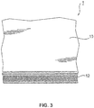
- eine Seitenansicht der Sonotrode aus
Fig. 1 , - Figur 4
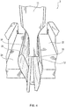
- eine Ausführungsform einer erfindungsgemäß bevorzugten Schweißvorrichtung in einer ersten Position,
- Figur 5
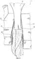
- eine Ausführungsform einer erfindungsgemäß bevorzugten Schweißvorrichtung in einer zweiten Position,
- Figur 6
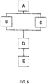
- einen schematischen Verfahrensablauf einer Ausführungsform des erfindungsgemäßen Schweißverfahrens.
- Die Ausführungsform der erfindungsgemäßen Schweißvorrichtung bzw. Reibschweißvorrichtung wird anhand des Verschweißens eines Kunststoffbeutels erläutert. Die zu verschweißenden Kunststoffbeutel bestehen beispielhaft aus zwei Folien, die als Material vorzugsweise thermoplastischen Kunststoff aufweisen, insbesondere Polyethylen (PE), Polypropylen (PP) oder Polyethylenterephthalat (PET) (siehe oben). Somit umfassen im nachfolgenden Beispiel alle Folien, und somit alle vier Fügeteile, das gleiche Material. Alternativ können die vier Fügeteile auch unterschiedliche Materialien umfassen. Verwendet werden die Kunststoffbeutel beispielsweise zur Lagerung und zum Transport von fließfähigen Produkten, wie Seife, Getränken u.ä.
Bezug nehmend auf dieFiguren 1 bis 3 wird zunächst die Sonotrode 1 erläutert. Die Sonotrode 1 umfasst einen Grundkörper 10 mit einer im Wesentlichen quaderförmingen Grundform. Der Grundkörper weist eine Längsachse L1 sowie eine erste 12 und eine zweite Arbeitsfläche 14 auf. Ein erstes Ende entlang der Längsachse L1 ist später im Betrieb in Eingriff mit einer Schweißvorrichtung, während das gegenüberliegende Ende als zweites Ende bezeichnet wird. Wird der Grundkörper 10 vom zweiten Ende her betrachtet, weist er vorzugsweise einen rechteckigen Umriss auf. Entlang der Längsachse L1 und/oder quer dazu ist die Sonotrode 1 im späteren Betrieb in einer Schweißvorrichtung 3 auslenkbar, was später detailliert erläutert wird. Benachbart des zweiten Endes sind die erste 12 und die zweite Arbeitsfläche 14 an gegenüberliegenden Seiten des Grundkörpers 10 angeordnet. Insbesondere sind die erste 12 und die zweite Arbeitsfläche 14 an den langen Seiten des rechteckigen Grundrisses angeordnet.
Wie in denFiguren 2 und3 besonders gut erkennbar, weist die erste Arbeitsfläche 12 eine Struktur auf, die vorzugsweise aus einer Mehrzahl von Erhebungen besteht. Die zweite Arbeitsfläche 14 weist erfindungsgemäß keine Struktur auf. Die Erhebungen sorgen für eine Vergrößerung der Oberfläche, mit der die erste Arbeitsfläche 12 später an den miteinander zu verschweißenden Fügeteilen anliegt. Somit sind die Fügeteile besser zwischen der Arbeitsfläche 12 und einer Druckfläche befestigbar, was nachfolgend unter Bezugnahme auf die Schweißvorrichtung erläutert wird. Erfindungsgemäß weist nur eine der Arbeitsflächen 12, 14 eine Struktur auf.
In denFiguren 4 und5 ist die Schweißvorrichtung 3 dargestellt. Die Schweißvorrichtung 3 umfasst die unter Bezugnahme auf dieFiguren 1 bis 3 beschriebene Sonotrode 1 sowie einen ersten Amboss 20 mit einer ersten Druckfläche 22 und einen zweiten Amboss 24 mit einer zweiten Druckfläche 26. Weiterhin sind inFigur 4 zwei umgelenkte Folien dargestellt, die zwischen der ersten Arbeitsfläche 12 und der ersten Druckfläche 22 sowie zwischen der zweiten Arbeitsfläche 14 und der zweiten Druckfläche 26 angeordnet sind. Die erste umgelenkte Folie stellt ein erstes 30 und ein zweites Fügeteil 32 dar und die zweite Folie stellt ein drittes 34 und ein viertes Fügeteil 36 dar.
InFigur 5 befinden sich die jeweiligen Arbeitsfläche 12, 14 der Sonotrode 1 in Eingriff mit der jeweiligen Druckfläche 22, 26 des jeweiligen Ambosses 20, 24. Zwischen der ersten Arbeitsfläche 12 und der ersten Druckfläche 22 sind das erste 30 und das zweite Fügeteil 32 angeordnet, während zwischen der zweiten Arbeitsfläche 14 und der zweiten Druckfläche 26 das dritte 34 und das vierte Fügeteil 36 angeordnet sind. Weiterhin ist erkennbar, dass die erste 22 und die zweite Druckfläche 26 eine Struktur aufweisen, insbesondere in der Form einer Mehrzahl von Erhebungen. Alternativ kann nur eine von beiden Druckfläche 22, 26 eine Struktur aufweisen oder keine der Druckflächen 22, 26 weist eine Struktur auf. - Durch die Struktur der Sonotrode 1 an der ersten 12 oder der zweiten Arbeitsfläche 14, die auch als Mitnahmestruktur bezeichnet wird, wird im Betrieb der Sonotrode 1 das daran anliegende Fügeteil in Schwingung versetzt. Durch die Struktur der ersten 22 und/oder der zweiten Druckfläche 26, die auch als Festhaltestruktur bezeichnet wird, wird das daran anliegende Fügeteil bezogen auf eine Bewegung der Sonotrode 1 vorzugsweise in seiner Position festgehalten. Mittels der jeweiligen Strukturen ist daher eine Reibschweißverbindung zwischen zwei Fügeteilen 30, 32 und/oder 34, 36 effektiv realisierbar, unabhängig von der Reihenfolge der Anordnung der Fügeteile 30, 32 und 34, 36 zwischen dem jeweiligen Amboss 20, 24 und der Arbeitsfläche 12, 14 der Sonotrode 1.
Eine Schwingung der Sonotrode 1 zum Verschweißen des ersten 30 und des zweiten Fügeteils 32 miteinander sowie des dritten 34 und des vierten Fügeteils 36 erfolgt gemäß einer bevorzugten Ausführungsform entlang der Längsachse L1 der Sonotrode 1. In diesem Fall bewegen sich die beiden Arbeitsflächen in einer jeweiligen Ebene parallel zur Arbeitsebene der Sonotrode entlang einer Geraden. In einer alternativen bevorzugten Ausführungsfrom erfolgt die Bewegung der beiden Arbeitsflächen innerhalb der jeweiligen Ebene parallel zur Arbeitsebene in Abhängigkeit von der Ausgestaltung der Sonotrode in einem anderen Bewegungsmuster, wie beispielsweise entlang einer krummlinigen Bahn. Dies bedeutet, dass, Bezug nehmend auf dieFiguren 4 und5 , die Schwingung also nicht nur nach oben und unten erfolgt, sondern auch nach vorne und hinten. Neben dem dargestellten gleichzeitigen Verschweißen von zwei Kunststoffbeuteln sind andere Abläufe möglich. Beispielsweise kann abwechselnd ein Kunststoffbeutel zwischen erster Arbeitsfläche 12 und erster Druckfläche 22 sowie zwischen zweiter Arbeitsfläche 14 und zweiter Druckfläche 26 hergestellt werden. - Nachfolgend Bezug nehmend auf
Figur 6 wird ein beispielhafter Verfahrensablauf eines Schweißverfahrens erläutert. In einem ersten Schritt A werden das erste 30, das zweite 32, das dritte 34 sowie das vierte Fügeteil 36 bereitgestellt. Nachfolgend werden das erste 30 und das zweite Fügeteil 32 in Schritt B zwischen der ersten Arbeitsfläche 12 und der ersten Druckfläche 22 angeordnet. Gleichzeitig, danach oder davor werden das dritte 34 und das vierte Fügeteil 36 in Schritt C zwischen der zweiten Arbeitsfläche 14 und der zweiten Druckfläche 26 angeordnet. - Nun werden vorzugsweise die jeweiligen Druckflächen 22, 26 in Richtung der jeweiligen Arbeitsflächen 12, 14 bewegt, so dass die entsprechenden Fügeteile 30 und 32 sowie 34 und 36 eingeklemmt werden. Sobald die Fügeteile 30 und 32 sowie 34 und 36 eingeklemmt sind, wird die Sonotrode 1 in Schritt D zum Schwingen entlang und/oder quer zur Längsachse L1 des Grundkörpers 10 angeregt. Auf diese Weise wird Fügeenergie lateral in eine erste und zweite Fügezone eingeleitet und es bildet sich eine Schweißverbindung zwischen dem ersten 30 und dem zweiten Fügeteil 32 und zwischen dem dritten 34 und dem vierten Fügeteil 36 aus.
- Aufgrund der Anordnung der Fügeteile 30 und 32 sowie 34 und 36 an den seitlichen Arbeitsflächen 12 und 14 der Sonotrode 1 wird die Fügeenergie in die Fügezone auch nur seitlich bzw. tangential eingeleitet. Dadurch werden bestimmte Nachteile des Ultraschallschweißens, wie lokale Über- oder Unterschweißungen, beim axialen Kontakt zwischen der Sonotrode 1 und dem zu verschweißenden Bereich vermieden. Eine Schwingung der Sonotrode 1 hängt hierbei insbesondere von dem zu verarbeitendem Material ab. Beispielsweise kann die Schwingung im Bereich von 20 bis 40 kHz, bevorzugt 20 bis 30 kHz liegen. Eine Variierung der Schweißparameter der Schweißvorrichtung 3 erfolgt vorzugsweise nur insoweit, als dass die Amplitude, die Schweißdauer oder die Einklemmkraft variiert werden. Insbesondere eine Variierung der Arbeitsfrequenz erfolgt jedoch nicht.
- In Schritt E werden die erste Arbeitsfläche 12 der Sonotrode 1 und die erste Druckfläche 22 des ersten Ambosses 20 auseinanderbewegt. Ebenso werden die zweite Arbeitsfläche 14 der Sonotrode 1 und die zweite Druckfläche 26 des zweiten Ambosses 24 auseinanderbewegt. Auf diese Weise sind die miteinander verschweißten ersten 30 und zweiten Fügeteile 32 und die dritten 34 und vierten Fügeteile 36 aus der Schweißvorrichtung 3 entnehmbar.
- Alternativ erfolgen die oben dargelegten Schritte nicht gleichzeitig sondern zeitversetzt bzw. im Wechsel zueinander. Beispielsweise folgt nach Schritt B der Schritt D nur mit dem Verschweißen des ersten 30 und des zweiten Fügeteils 32. Gleichzeitig mit diesem Schritt D erfolgt Schritt C. Wenn der Schritt D für das erste 30 und das zweite Fügeteil 32 beendet ist, wird Schritt E für das erste 30 und das zweite Fügeteil 32 durchgeführt, während Schritt D für das dritte 34 und das vierte Fügeteil 36 durchgeführt wird.
- In einer weiteren Ausführungsform werden die Sonotrode 1 sowie der erste 20 und der zweite Amboss 24 während der Schritte B bis E zwischen einer ersten und einer zweiten Position hin- und herbewegt. Auf diese Weise erfolgt ein Weitertransport der herzustellenden Kunststoffbeutel auch in der Schweißvorrichtung 3, so dass der Verfahrensablauf weiter optimiert ist.
-
- 1
- Sonotrode
- 3
- Schweißvorrichtung
- 10
- Grundkörper
- 12
- erste Arbeitsfläche
- 14
- zweite Arbeitsfläche
- 20
- erster Amboss
- 22
- erste Druckfläche
- 24
- zweiter Amboss
- 26
- zweite Druckfläche
- 30
- erstes Fügeteil
- 32
- zweites Fügeteil
- 34
- drittes Fügeteil
- 36
- viertes Fügeteil
- L1
- Längsachse
Claims (7)
- Sonotrode (1) zum Reibschweißen von mindestens zwei Fügeteilen (30, 32; 34, 36), die zumindest teilweise aus verschweißbarem Kunststoff bestehen, umfassend:a) einen Grundkörper (10), der eine Längsachse (L1) aufweist, die in einer Arbeitsebene der Sonotrode (1) liegt, wobei die Sonotrode (1) im Betrieb innerhalb dieser Arbeitsebene auslenkbar ist, wobeib) eine erste Arbeitsfläche (12) bezogen auf die Längsachse (L1) lateral an der Sonotrode (1) angeordnet ist, so dass Fügeenergie lateral in eine erste Fügezone zwischen einem ersten (30) und einem zweiten Fügeteil (32) einleitbar ist, undc) eine zweite Arbeitsfläche (14) bezogen auf die Längsachse (L1) lateral an der Sonotrode (1) angeordnet ist, so dass Fügeenergie lateral in eine zweite Fügezone zwischen einem dritten (34) und einem vierten Fügeteil (36) einleitbar ist, wobeid) sich im Betrieb die erste Arbeitsfläche (12) in einer ersten Ebene parallel zur Arbeitsebene und die zweite Arbeitsfläche (14) sich in einer zweiten Ebene parallel zur Arbeitsebene bewegen, unde) die erste (12) oder die zweite Arbeitsfläche (14) der Sonotrode (1) eine Struktur aufweist, insbesondere in Form einer Mehrzahl von Erhebungen, und die verbleibende von der ersten (12) oder der zweiten Arbeitsfläche (14) der Sonotrode (1) keine Struktur aufweist.
- Sonotrode (1) gemäß Patentanspruch 1, wobei die erste (12) und die zweite Arbeitsfläche (14) auf gegenüberliegenden Seiten der Sonotrode (1) angeordnet sind.
- Schweißvorrichtung (3) zum Reibschweißen von mindestens zwei Fügeteilen (30, 32; 34, 36), die zumindest teilweise aus verschweißbarem Kunststoff bestehen, umfassend:a) eine Sonotrode (1) gemäß einem der Patentansprüche 1 oder 2 mit einer ersten Arbeitsfläche (12), die bezogen auf eine Längsachse (L1) eines Grundkörpers (10) lateral angeordnet ist, und mit einer zweiten Arbeitsfläche (14), die bezogen auf die Längsachse (L1) des Grundkörpers (10) ebenfalls lateral angeordnet ist, sowieb) einen ersten Amboss (20) mit einer ersten Druckfläche (22) und einen zweiten Amboss (24) mit einer zweiten Druckfläche (26), wobeic) im Betrieb der Schweißvorrichtung (3) ein erstes (30) und ein zweites Fügeteil (32) mittels der ersten Druckfläche (22) des ersten Ambosses (20) und der ersten lateralen Arbeitsfläche (12) miteinander verschweißbar sind undd) ein drittes (34) und ein viertes Fügeteil (36) sind mittels der zweiten Druckfläche (26) des zweiten Ambosses (24) und der zweiten lateralen Arbeitsfläche (14) miteinander verschweißbar.
- Schweißvorrichtung (3) gemäß Patentanspruch 3, wobei die erste (22) und/oder die zweite Druckfläche (26) eine Struktur aufweist, insbesondere in Form einer Mehrzahl von Erhebungen.
- Schweißverfahren mit einer Schweißvorrichtung (3) gemäß einem der Patentansprüche 3 oder 4, das die Schritte umfasst:a) Bereitstellen (A) eines ersten (30) und eines zweiten Fügeteils (32) sowie eines dritten (34) und eines vierten Fügeteils (36), die zumindest teilweise aus verschweißbarem Kunststoff bestehen,b) Anordnen (B) des ersten (30) und des zweiten Fügeteils (32) zwischen einer lateral zur Schwingungsrichtung einer Sonotrode (1) angeordneten ersten Arbeitsfläche (12) der Sonotrode (1) und einer ersten Druckfläche (22) eines ersten Ambosses (20),c) Anordnen (C) des dritten (34) und des vierten Fügeteils (36) zwischen einer lateral zur Schwingungsrichtung der Sonotrode (1) angeordneten zweiten Arbeitsfläche (14) der Sonotrode (1) und einer zweiten Druckfläche (26) eines zweiten Ambosses (24),d) Anregen (D) der Sonotrode (1) zum Schwingen entlang und/oder quer zu einer Längsachse (L1) des Grundkörpers (16), wodurch Fügeenergie lateral in eine erste und/oder zweite Fügezone einleitbar ist und sich eine Schweißverbindung zwischen dem ersten (30) und dem zweiten Fügeteil (32) und/oder zwischen dem dritten (34) und dem vierten Fügeteil (36) ausbildet, unde) Auseinanderbewegen (E) der ersten Arbeitsfläche (12) der Sonotrode (1) und der ersten Druckfläche (22) des ersten Ambosses (20) und/oder der zweiten Arbeitsfläche (14) der Sonotrode (1) und der zweiten Druckfläche (26) des zweiten Ambosses (24), damit die miteinander verschweißten ersten (30) und zweiten Fügeteile (32) und/oder dritten (34) und vierten Fügeteile (36) aus der Schweißvorrichtung (3) entnehmbar sind.
- Schweißverfahren gemäß Patentanspruch 5, wobei eine Schwingung der Sonotrode (1) im Ultraschallbereich erfolgt, vorzugsweise zwischen 20 und 40 kHz, besonders bevorzugt zwischen 20 und 30 kHz.
- Schweißverfahren gemäß einem der Patentansprüche 5 oder 6, wobei das erste (30) und das zweite Fügeteil (32) zumindest teilweise zeitgleich mit dem dritten (34) und dem vierten Fügeteil (36) in Schritt d. verschweißt wird.
Applications Claiming Priority (1)
| Application Number | Priority Date | Filing Date | Title |
|---|---|---|---|
| DE102014223907.9A DE102014223907A1 (de) | 2014-11-24 | 2014-11-24 | Sonotrode, Schweißvorrichtung mit Sonotrode sowie dazugehöriges Schweißverfahren |
Publications (3)
| Publication Number | Publication Date |
|---|---|
| EP3023224A2 EP3023224A2 (de) | 2016-05-25 |
| EP3023224A3 EP3023224A3 (de) | 2016-06-22 |
| EP3023224B1 true EP3023224B1 (de) | 2019-03-13 |
Family
ID=54151146
Family Applications (1)
| Application Number | Title | Priority Date | Filing Date |
|---|---|---|---|
| EP15185837.0A Active EP3023224B1 (de) | 2014-11-24 | 2015-09-18 | Sonotrode, schweissvorrichtung mit sonotrode sowie dazugehöriges schweissverfahren |
Country Status (3)
| Country | Link |
|---|---|
| EP (1) | EP3023224B1 (de) |
| DE (1) | DE102014223907A1 (de) |
| ES (1) | ES2730956T3 (de) |
Cited By (1)
| Publication number | Priority date | Publication date | Assignee | Title |
|---|---|---|---|---|
| DE102023120065A1 (de) * | 2023-07-27 | 2025-02-13 | Branson Ultraschall Niederlassung Der Emerson Technologies Gmbh & Co. Ohg | Sonotrode, Schweißvorrichtung mit Sonotrode sowie dazugehöriges Schweißverfahren und Positionierverfahren |
Family Cites Families (11)
| Publication number | Priority date | Publication date | Assignee | Title |
|---|---|---|---|---|
| US3376179A (en) * | 1964-06-12 | 1968-04-02 | Cavitron Ultrasonics Inc | Method and apparatus for high frequency joining or sealing of thermosoftening materials |
| JPS5840490B2 (ja) * | 1978-06-20 | 1983-09-06 | ワイケイケイ株式会社 | 熱可塑性合成樹脂製フアスナ−エレメントの上下脚部の溶着方法および装置 |
| US4767492A (en) * | 1986-04-18 | 1988-08-30 | Pola Chemical Industries, Inc. | Ultrasonic fuse-bonding sealing apparatus with improved contact surfaces |
| US4713131A (en) * | 1986-06-05 | 1987-12-15 | Obeda Edward G | Apparatus and method for ultrasonically joining sheets of termoplastic materials |
| DE8811803U1 (de) * | 1988-09-17 | 1989-02-23 | Wag Apparatetechnik GmbH, 6472 Altenstadt | Ultraschallschweißgerät |
| US7329450B2 (en) * | 2002-10-16 | 2008-02-12 | Ultrafab, Inc. | Textile backed pile article and method for making same |
| AT412438B (de) * | 2002-11-29 | 2005-03-25 | Bege Privatstiftung | Applikator für ersatzhaarsträhnen |
| FR2880520B1 (fr) * | 2005-01-12 | 2007-04-27 | Fastmag Soc Par Actions Simpli | Procede d'elaboration d'un element d'assemblage non permanent et element d'assemblage obtenu par ce procede |
| US20120153006A1 (en) * | 2010-12-16 | 2012-06-21 | Lg Chem, Ltd. | Ultrasonic welding system and method for forming a weld joint |
| DE102011006930B4 (de) * | 2011-04-07 | 2015-08-20 | Widmann Maschinen GmbH & Co. KG | Schweißvorrichtung |
| KR102073189B1 (ko) * | 2013-04-04 | 2020-02-04 | 삼성에스디아이 주식회사 | 이차전지용 용접혼 |
-
2014
- 2014-11-24 DE DE102014223907.9A patent/DE102014223907A1/de not_active Withdrawn
-
2015
- 2015-09-18 EP EP15185837.0A patent/EP3023224B1/de active Active
- 2015-09-18 ES ES15185837T patent/ES2730956T3/es active Active
Non-Patent Citations (1)
| Title |
|---|
| None * |
Cited By (1)
| Publication number | Priority date | Publication date | Assignee | Title |
|---|---|---|---|---|
| DE102023120065A1 (de) * | 2023-07-27 | 2025-02-13 | Branson Ultraschall Niederlassung Der Emerson Technologies Gmbh & Co. Ohg | Sonotrode, Schweißvorrichtung mit Sonotrode sowie dazugehöriges Schweißverfahren und Positionierverfahren |
Also Published As
| Publication number | Publication date |
|---|---|
| ES2730956T3 (es) | 2019-11-13 |
| DE102014223907A1 (de) | 2016-05-25 |
| EP3023224A3 (de) | 2016-06-22 |
| EP3023224A2 (de) | 2016-05-25 |
Similar Documents
| Publication | Publication Date | Title |
|---|---|---|
| DE69926758T2 (de) | Ultraschall-siegler | |
| EP2988919B1 (de) | Ultraschallschweissvorrichtung mit mehreren sonotroden | |
| EP2219848B1 (de) | Sonotrode mit u-spalt | |
| DE102010028932B4 (de) | Verfahren zum Ultraschallverschweißen zweier Beutelfolien mit einem Spout | |
| EP3102387B1 (de) | Ultraschallschweissvorrichtung mit vorwärmeinrichtung | |
| EP2945793B1 (de) | Ultraschallschweissvorrichtung mit schwingungsentkoppeltem gegenwerkzeug | |
| DE4313875C3 (de) | Vorrichtung zum Herstellen von Einsteckhüllen oder Einbanddecken | |
| EP3079895B1 (de) | Verfahren zum herstellen einer verpackung und verpackungsmaschine | |
| WO2017144967A1 (de) | Umreifungsvorrichtung mit einer ultraschallschweisseinrichtung | |
| EP2504150B1 (de) | Verfahren zum verschliessen eines sackkörpers | |
| DE102020117463A1 (de) | Gegenwerkzeug, Ultraschallschweißmaschine sowie Verfahren zur Erzeugung einer Dicht- und Kosmetiknaht | |
| DE69806069T2 (de) | Ultraschall-hornstrahler | |
| EP0447875B1 (de) | Filterelement aus einem zick-zack-förmig gefalteten, stern- oder plattenförmig angeordneten Filtermaterial | |
| AT508982B1 (de) | Verfahren zum verschliessen eines sackkörpers | |
| WO2000010795A1 (de) | Verfahren zur herstellung von heissiegel-verpackungen und ein werkzeug zur durchführung des verfahrens | |
| EP3023224A2 (de) | Sonotrode, schweissvorrichtung mit sonotrode sowie dazugehöriges schweissverfahren | |
| WO2022043107A1 (de) | Verfahren zum verbinden zweier fügeflächen | |
| EP2225089B1 (de) | Verfahren zum verbinden von folien | |
| DE102011006930A1 (de) | Schweißvorrichtung und Schweißblech | |
| EP3835035A1 (de) | Verfahren zum verbinden von werkstücken und zusammengesetzter gegenstand | |
| DE202009007996U1 (de) | Ultraschall-Schweißwerkzeug | |
| DE102009024258A1 (de) | Ultraschall-Schweißwerkzeug | |
| WO2010139464A1 (de) | Ultraschall-schweisswerkzeug | |
| WO2023061803A1 (de) | Werkzeug für eine ultraschallschweissvorrichtung und verfahren damit | |
| DE4412087A1 (de) | Verfahren zum Verbinden zweier Kunststoffbahnen und Vorrichtung zur Durchführung des Verfahrens |
Legal Events
| Date | Code | Title | Description |
|---|---|---|---|
| PUAL | Search report despatched |
Free format text: ORIGINAL CODE: 0009013 |
|
| AK | Designated contracting states |
Kind code of ref document: A2 Designated state(s): AL AT BE BG CH CY CZ DE DK EE ES FI FR GB GR HR HU IE IS IT LI LT LU LV MC MK MT NL NO PL PT RO RS SE SI SK SM TR |
|
| AX | Request for extension of the european patent |
Extension state: BA ME |
|
| PUAI | Public reference made under article 153(3) epc to a published international application that has entered the european phase |
Free format text: ORIGINAL CODE: 0009012 |
|
| AK | Designated contracting states |
Kind code of ref document: A3 Designated state(s): AL AT BE BG CH CY CZ DE DK EE ES FI FR GB GR HR HU IE IS IT LI LT LU LV MC MK MT NL NO PL PT RO RS SE SI SK SM TR |
|
| AX | Request for extension of the european patent |
Extension state: BA ME |
|
| RIC1 | Information provided on ipc code assigned before grant |
Ipc: B29C 65/08 20060101ALI20160518BHEP Ipc: B29C 65/06 20060101AFI20160518BHEP |
|
| STAA | Information on the status of an ep patent application or granted ep patent |
Free format text: STATUS: REQUEST FOR EXAMINATION WAS MADE |
|
| 17P | Request for examination filed |
Effective date: 20161110 |
|
| RBV | Designated contracting states (corrected) |
Designated state(s): AL AT BE BG CH CY CZ DE DK EE ES FI FR GB GR HR HU IE IS IT LI LT LU LV MC MK MT NL NO PL PT RO RS SE SI SK SM TR |
|
| GRAP | Despatch of communication of intention to grant a patent |
Free format text: ORIGINAL CODE: EPIDOSNIGR1 |
|
| STAA | Information on the status of an ep patent application or granted ep patent |
Free format text: STATUS: GRANT OF PATENT IS INTENDED |
|
| INTG | Intention to grant announced |
Effective date: 20181005 |
|
| GRAS | Grant fee paid |
Free format text: ORIGINAL CODE: EPIDOSNIGR3 |
|
| GRAA | (expected) grant |
Free format text: ORIGINAL CODE: 0009210 |
|
| STAA | Information on the status of an ep patent application or granted ep patent |
Free format text: STATUS: THE PATENT HAS BEEN GRANTED |
|
| AK | Designated contracting states |
Kind code of ref document: B1 Designated state(s): AL AT BE BG CH CY CZ DE DK EE ES FI FR GB GR HR HU IE IS IT LI LT LU LV MC MK MT NL NO PL PT RO RS SE SI SK SM TR |
|
| REG | Reference to a national code |
Ref country code: GB Ref legal event code: FG4D Free format text: NOT ENGLISH |
|
| REG | Reference to a national code |
Ref country code: CH Ref legal event code: EP Ref country code: AT Ref legal event code: REF Ref document number: 1107115 Country of ref document: AT Kind code of ref document: T Effective date: 20190315 |
|
| REG | Reference to a national code |
Ref country code: IE Ref legal event code: FG4D Free format text: LANGUAGE OF EP DOCUMENT: GERMAN |
|
| REG | Reference to a national code |
Ref country code: DE Ref legal event code: R096 Ref document number: 502015008308 Country of ref document: DE |
|
| REG | Reference to a national code |
Ref country code: CH Ref legal event code: NV Representative=s name: MICHELI AND CIE SA, CH |
|
| REG | Reference to a national code |
Ref country code: NL Ref legal event code: MP Effective date: 20190313 |
|
| REG | Reference to a national code |
Ref country code: LT Ref legal event code: MG4D |
|
| PG25 | Lapsed in a contracting state [announced via postgrant information from national office to epo] |
Ref country code: SE Free format text: LAPSE BECAUSE OF FAILURE TO SUBMIT A TRANSLATION OF THE DESCRIPTION OR TO PAY THE FEE WITHIN THE PRESCRIBED TIME-LIMIT Effective date: 20190313 Ref country code: NO Free format text: LAPSE BECAUSE OF FAILURE TO SUBMIT A TRANSLATION OF THE DESCRIPTION OR TO PAY THE FEE WITHIN THE PRESCRIBED TIME-LIMIT Effective date: 20190613 Ref country code: FI Free format text: LAPSE BECAUSE OF FAILURE TO SUBMIT A TRANSLATION OF THE DESCRIPTION OR TO PAY THE FEE WITHIN THE PRESCRIBED TIME-LIMIT Effective date: 20190313 Ref country code: LT Free format text: LAPSE BECAUSE OF FAILURE TO SUBMIT A TRANSLATION OF THE DESCRIPTION OR TO PAY THE FEE WITHIN THE PRESCRIBED TIME-LIMIT Effective date: 20190313 |
|
| PG25 | Lapsed in a contracting state [announced via postgrant information from national office to epo] |
Ref country code: GR Free format text: LAPSE BECAUSE OF FAILURE TO SUBMIT A TRANSLATION OF THE DESCRIPTION OR TO PAY THE FEE WITHIN THE PRESCRIBED TIME-LIMIT Effective date: 20190614 Ref country code: RS Free format text: LAPSE BECAUSE OF FAILURE TO SUBMIT A TRANSLATION OF THE DESCRIPTION OR TO PAY THE FEE WITHIN THE PRESCRIBED TIME-LIMIT Effective date: 20190313 Ref country code: BG Free format text: LAPSE BECAUSE OF FAILURE TO SUBMIT A TRANSLATION OF THE DESCRIPTION OR TO PAY THE FEE WITHIN THE PRESCRIBED TIME-LIMIT Effective date: 20190613 Ref country code: NL Free format text: LAPSE BECAUSE OF FAILURE TO SUBMIT A TRANSLATION OF THE DESCRIPTION OR TO PAY THE FEE WITHIN THE PRESCRIBED TIME-LIMIT Effective date: 20190313 Ref country code: HR Free format text: LAPSE BECAUSE OF FAILURE TO SUBMIT A TRANSLATION OF THE DESCRIPTION OR TO PAY THE FEE WITHIN THE PRESCRIBED TIME-LIMIT Effective date: 20190313 Ref country code: LV Free format text: LAPSE BECAUSE OF FAILURE TO SUBMIT A TRANSLATION OF THE DESCRIPTION OR TO PAY THE FEE WITHIN THE PRESCRIBED TIME-LIMIT Effective date: 20190313 |
|
| PG25 | Lapsed in a contracting state [announced via postgrant information from national office to epo] |
Ref country code: SK Free format text: LAPSE BECAUSE OF FAILURE TO SUBMIT A TRANSLATION OF THE DESCRIPTION OR TO PAY THE FEE WITHIN THE PRESCRIBED TIME-LIMIT Effective date: 20190313 Ref country code: RO Free format text: LAPSE BECAUSE OF FAILURE TO SUBMIT A TRANSLATION OF THE DESCRIPTION OR TO PAY THE FEE WITHIN THE PRESCRIBED TIME-LIMIT Effective date: 20190313 Ref country code: EE Free format text: LAPSE BECAUSE OF FAILURE TO SUBMIT A TRANSLATION OF THE DESCRIPTION OR TO PAY THE FEE WITHIN THE PRESCRIBED TIME-LIMIT Effective date: 20190313 Ref country code: AL Free format text: LAPSE BECAUSE OF FAILURE TO SUBMIT A TRANSLATION OF THE DESCRIPTION OR TO PAY THE FEE WITHIN THE PRESCRIBED TIME-LIMIT Effective date: 20190313 Ref country code: PT Free format text: LAPSE BECAUSE OF FAILURE TO SUBMIT A TRANSLATION OF THE DESCRIPTION OR TO PAY THE FEE WITHIN THE PRESCRIBED TIME-LIMIT Effective date: 20190713 Ref country code: CZ Free format text: LAPSE BECAUSE OF FAILURE TO SUBMIT A TRANSLATION OF THE DESCRIPTION OR TO PAY THE FEE WITHIN THE PRESCRIBED TIME-LIMIT Effective date: 20190313 |
|
| REG | Reference to a national code |
Ref country code: ES Ref legal event code: FG2A Ref document number: 2730956 Country of ref document: ES Kind code of ref document: T3 Effective date: 20191113 |
|
| PG25 | Lapsed in a contracting state [announced via postgrant information from national office to epo] |
Ref country code: SM Free format text: LAPSE BECAUSE OF FAILURE TO SUBMIT A TRANSLATION OF THE DESCRIPTION OR TO PAY THE FEE WITHIN THE PRESCRIBED TIME-LIMIT Effective date: 20190313 Ref country code: PL Free format text: LAPSE BECAUSE OF FAILURE TO SUBMIT A TRANSLATION OF THE DESCRIPTION OR TO PAY THE FEE WITHIN THE PRESCRIBED TIME-LIMIT Effective date: 20190313 |
|
| REG | Reference to a national code |
Ref country code: DE Ref legal event code: R097 Ref document number: 502015008308 Country of ref document: DE |
|
| PG25 | Lapsed in a contracting state [announced via postgrant information from national office to epo] |
Ref country code: IS Free format text: LAPSE BECAUSE OF FAILURE TO SUBMIT A TRANSLATION OF THE DESCRIPTION OR TO PAY THE FEE WITHIN THE PRESCRIBED TIME-LIMIT Effective date: 20190713 |
|
| PLBE | No opposition filed within time limit |
Free format text: ORIGINAL CODE: 0009261 |
|
| STAA | Information on the status of an ep patent application or granted ep patent |
Free format text: STATUS: NO OPPOSITION FILED WITHIN TIME LIMIT |
|
| PG25 | Lapsed in a contracting state [announced via postgrant information from national office to epo] |
Ref country code: DK Free format text: LAPSE BECAUSE OF FAILURE TO SUBMIT A TRANSLATION OF THE DESCRIPTION OR TO PAY THE FEE WITHIN THE PRESCRIBED TIME-LIMIT Effective date: 20190313 |
|
| 26N | No opposition filed |
Effective date: 20191216 |
|
| PG25 | Lapsed in a contracting state [announced via postgrant information from national office to epo] |
Ref country code: SI Free format text: LAPSE BECAUSE OF FAILURE TO SUBMIT A TRANSLATION OF THE DESCRIPTION OR TO PAY THE FEE WITHIN THE PRESCRIBED TIME-LIMIT Effective date: 20190313 |
|
| PG25 | Lapsed in a contracting state [announced via postgrant information from national office to epo] |
Ref country code: TR Free format text: LAPSE BECAUSE OF FAILURE TO SUBMIT A TRANSLATION OF THE DESCRIPTION OR TO PAY THE FEE WITHIN THE PRESCRIBED TIME-LIMIT Effective date: 20190313 |
|
| PG25 | Lapsed in a contracting state [announced via postgrant information from national office to epo] |
Ref country code: MC Free format text: LAPSE BECAUSE OF FAILURE TO SUBMIT A TRANSLATION OF THE DESCRIPTION OR TO PAY THE FEE WITHIN THE PRESCRIBED TIME-LIMIT Effective date: 20190313 |
|
| PG25 | Lapsed in a contracting state [announced via postgrant information from national office to epo] |
Ref country code: LU Free format text: LAPSE BECAUSE OF NON-PAYMENT OF DUE FEES Effective date: 20190918 Ref country code: IE Free format text: LAPSE BECAUSE OF NON-PAYMENT OF DUE FEES Effective date: 20190918 |
|
| REG | Reference to a national code |
Ref country code: BE Ref legal event code: MM Effective date: 20190930 |
|
| PG25 | Lapsed in a contracting state [announced via postgrant information from national office to epo] |
Ref country code: BE Free format text: LAPSE BECAUSE OF NON-PAYMENT OF DUE FEES Effective date: 20190930 |
|
| PG25 | Lapsed in a contracting state [announced via postgrant information from national office to epo] |
Ref country code: CY Free format text: LAPSE BECAUSE OF FAILURE TO SUBMIT A TRANSLATION OF THE DESCRIPTION OR TO PAY THE FEE WITHIN THE PRESCRIBED TIME-LIMIT Effective date: 20190313 |
|
| PG25 | Lapsed in a contracting state [announced via postgrant information from national office to epo] |
Ref country code: MT Free format text: LAPSE BECAUSE OF FAILURE TO SUBMIT A TRANSLATION OF THE DESCRIPTION OR TO PAY THE FEE WITHIN THE PRESCRIBED TIME-LIMIT Effective date: 20190313 Ref country code: HU Free format text: LAPSE BECAUSE OF FAILURE TO SUBMIT A TRANSLATION OF THE DESCRIPTION OR TO PAY THE FEE WITHIN THE PRESCRIBED TIME-LIMIT; INVALID AB INITIO Effective date: 20150918 |
|
| REG | Reference to a national code |
Ref country code: AT Ref legal event code: MM01 Ref document number: 1107115 Country of ref document: AT Kind code of ref document: T Effective date: 20200918 |
|
| PG25 | Lapsed in a contracting state [announced via postgrant information from national office to epo] |
Ref country code: AT Free format text: LAPSE BECAUSE OF NON-PAYMENT OF DUE FEES Effective date: 20200918 |
|
| PG25 | Lapsed in a contracting state [announced via postgrant information from national office to epo] |
Ref country code: MK Free format text: LAPSE BECAUSE OF FAILURE TO SUBMIT A TRANSLATION OF THE DESCRIPTION OR TO PAY THE FEE WITHIN THE PRESCRIBED TIME-LIMIT Effective date: 20190313 |
|
| P01 | Opt-out of the competence of the unified patent court (upc) registered |
Effective date: 20230523 |
|
| REG | Reference to a national code |
Ref country code: CH Ref legal event code: U11 Free format text: ST27 STATUS EVENT CODE: U-0-0-U10-U11 (AS PROVIDED BY THE NATIONAL OFFICE) Effective date: 20251001 |
|
| PGFP | Annual fee paid to national office [announced via postgrant information from national office to epo] |
Ref country code: GB Payment date: 20250923 Year of fee payment: 11 |
|
| PGFP | Annual fee paid to national office [announced via postgrant information from national office to epo] |
Ref country code: FR Payment date: 20250924 Year of fee payment: 11 |
|
| PGFP | Annual fee paid to national office [announced via postgrant information from national office to epo] |
Ref country code: DE Payment date: 20251126 Year of fee payment: 11 |
|
| PGFP | Annual fee paid to national office [announced via postgrant information from national office to epo] |
Ref country code: IT Payment date: 20250930 Year of fee payment: 11 |
|
| PGFP | Annual fee paid to national office [announced via postgrant information from national office to epo] |
Ref country code: CH Payment date: 20251001 Year of fee payment: 11 |
|
| PGFP | Annual fee paid to national office [announced via postgrant information from national office to epo] |
Ref country code: ES Payment date: 20251020 Year of fee payment: 11 |