EP3022143B1 - Method and assembly for securing the end of a web roll - Google Patents
Method and assembly for securing the end of a web roll Download PDFInfo
- Publication number
- EP3022143B1 EP3022143B1 EP14823505.4A EP14823505A EP3022143B1 EP 3022143 B1 EP3022143 B1 EP 3022143B1 EP 14823505 A EP14823505 A EP 14823505A EP 3022143 B1 EP3022143 B1 EP 3022143B1
- Authority
- EP
- European Patent Office
- Prior art keywords
- tapes
- conveyor
- rolls
- tape
- web
- Prior art date
- Legal status (The legal status is an assumption and is not a legal conclusion. Google has not performed a legal analysis and makes no representation as to the accuracy of the status listed.)
- Active
Links
- 238000000034 method Methods 0.000 title claims description 21
- 239000000463 material Substances 0.000 claims description 21
- 238000000576 coating method Methods 0.000 claims description 8
- 239000011248 coating agent Substances 0.000 claims description 7
- 239000000853 adhesive Substances 0.000 claims description 5
- 230000001070 adhesive effect Effects 0.000 claims description 5
- 230000000717 retained effect Effects 0.000 claims description 4
- 230000002776 aggregation Effects 0.000 claims description 2
- 238000004220 aggregation Methods 0.000 claims description 2
- 239000000123 paper Substances 0.000 description 29
- 238000004519 manufacturing process Methods 0.000 description 13
- 238000004804 winding Methods 0.000 description 11
- 239000002390 adhesive tape Substances 0.000 description 6
- 241001417494 Sciaenidae Species 0.000 description 3
- 230000008859 change Effects 0.000 description 3
- 238000005520 cutting process Methods 0.000 description 3
- 230000008569 process Effects 0.000 description 3
- 238000007796 conventional method Methods 0.000 description 2
- 239000003292 glue Substances 0.000 description 2
- 238000005192 partition Methods 0.000 description 2
- 239000004033 plastic Substances 0.000 description 2
- 230000000284 resting effect Effects 0.000 description 2
- 230000037303 wrinkles Effects 0.000 description 2
- 239000004809 Teflon Substances 0.000 description 1
- 229920006362 Teflon® Polymers 0.000 description 1
- 230000006978 adaptation Effects 0.000 description 1
- 229910052782 aluminium Inorganic materials 0.000 description 1
- XAGFODPZIPBFFR-UHFFFAOYSA-N aluminium Chemical compound [Al] XAGFODPZIPBFFR-UHFFFAOYSA-N 0.000 description 1
- 238000005452 bending Methods 0.000 description 1
- 230000015572 biosynthetic process Effects 0.000 description 1
- 239000002131 composite material Substances 0.000 description 1
- 230000008878 coupling Effects 0.000 description 1
- 238000010168 coupling process Methods 0.000 description 1
- 238000005859 coupling reaction Methods 0.000 description 1
- 239000011888 foil Substances 0.000 description 1
- 229910052751 metal Inorganic materials 0.000 description 1
- 239000002184 metal Substances 0.000 description 1
- 230000003287 optical effect Effects 0.000 description 1
- 238000004806 packaging method and process Methods 0.000 description 1
- 239000011087 paperboard Substances 0.000 description 1
- 239000002985 plastic film Substances 0.000 description 1
- 238000007639 printing Methods 0.000 description 1
- 238000004064 recycling Methods 0.000 description 1
Images


Classifications
-
- B—PERFORMING OPERATIONS; TRANSPORTING
- B65—CONVEYING; PACKING; STORING; HANDLING THIN OR FILAMENTARY MATERIAL
- B65H—HANDLING THIN OR FILAMENTARY MATERIAL, e.g. SHEETS, WEBS, CABLES
- B65H19/00—Changing the web roll
- B65H19/22—Changing the web roll in winding mechanisms or in connection with winding operations
- B65H19/29—Securing the trailing end of the wound web to the web roll
-
- B—PERFORMING OPERATIONS; TRANSPORTING
- B65—CONVEYING; PACKING; STORING; HANDLING THIN OR FILAMENTARY MATERIAL
- B65H—HANDLING THIN OR FILAMENTARY MATERIAL, e.g. SHEETS, WEBS, CABLES
- B65H2301/00—Handling processes for sheets or webs
- B65H2301/40—Type of handling process
- B65H2301/41—Winding, unwinding
- B65H2301/412—Roll
- B65H2301/4128—Multiple rolls
- B65H2301/41282—Multiple rolls coaxially arranged
-
- B—PERFORMING OPERATIONS; TRANSPORTING
- B65—CONVEYING; PACKING; STORING; HANDLING THIN OR FILAMENTARY MATERIAL
- B65H—HANDLING THIN OR FILAMENTARY MATERIAL, e.g. SHEETS, WEBS, CABLES
- B65H2301/00—Handling processes for sheets or webs
- B65H2301/40—Type of handling process
- B65H2301/41—Winding, unwinding
- B65H2301/414—Winding
- B65H2301/4144—Finishing winding process
- B65H2301/41441—Finishing winding process and blocking outer layers against falling apart
- B65H2301/41442—Specified by the sealing medium sealing used
- B65H2301/414422—Adhesive tape
-
- B—PERFORMING OPERATIONS; TRANSPORTING
- B65—CONVEYING; PACKING; STORING; HANDLING THIN OR FILAMENTARY MATERIAL
- B65H—HANDLING THIN OR FILAMENTARY MATERIAL, e.g. SHEETS, WEBS, CABLES
- B65H2301/00—Handling processes for sheets or webs
- B65H2301/40—Type of handling process
- B65H2301/41—Winding, unwinding
- B65H2301/414—Winding
- B65H2301/4144—Finishing winding process
- B65H2301/41441—Finishing winding process and blocking outer layers against falling apart
- B65H2301/41443—Specified by the place to where the sealing medium is applied
- B65H2301/414433—Specified by the place to where the sealing medium is applied onto the roll
-
- B—PERFORMING OPERATIONS; TRANSPORTING
- B65—CONVEYING; PACKING; STORING; HANDLING THIN OR FILAMENTARY MATERIAL
- B65H—HANDLING THIN OR FILAMENTARY MATERIAL, e.g. SHEETS, WEBS, CABLES
- B65H2301/00—Handling processes for sheets or webs
- B65H2301/40—Type of handling process
- B65H2301/41—Winding, unwinding
- B65H2301/414—Winding
- B65H2301/4144—Finishing winding process
- B65H2301/41441—Finishing winding process and blocking outer layers against falling apart
- B65H2301/41444—Specified by process phase during which sealing /securing is performed
- B65H2301/414443—Sealing or securing within the winding station
-
- B—PERFORMING OPERATIONS; TRANSPORTING
- B65—CONVEYING; PACKING; STORING; HANDLING THIN OR FILAMENTARY MATERIAL
- B65H—HANDLING THIN OR FILAMENTARY MATERIAL, e.g. SHEETS, WEBS, CABLES
- B65H2301/00—Handling processes for sheets or webs
- B65H2301/40—Type of handling process
- B65H2301/41—Winding, unwinding
- B65H2301/414—Winding
- B65H2301/4148—Winding slitting
-
- B—PERFORMING OPERATIONS; TRANSPORTING
- B65—CONVEYING; PACKING; STORING; HANDLING THIN OR FILAMENTARY MATERIAL
- B65H—HANDLING THIN OR FILAMENTARY MATERIAL, e.g. SHEETS, WEBS, CABLES
- B65H2404/00—Parts for transporting or guiding the handled material
- B65H2404/20—Belts
- B65H2404/26—Particular arrangement of belt, or belts
- B65H2404/269—Particular arrangement of belt, or belts other arrangements
- B65H2404/2693—Arrangement of belts on movable frame
-
- B—PERFORMING OPERATIONS; TRANSPORTING
- B65—CONVEYING; PACKING; STORING; HANDLING THIN OR FILAMENTARY MATERIAL
- B65H—HANDLING THIN OR FILAMENTARY MATERIAL, e.g. SHEETS, WEBS, CABLES
- B65H2406/00—Means using fluid
- B65H2406/30—Suction means
- B65H2406/31—Suction box; Suction chambers
-
- B—PERFORMING OPERATIONS; TRANSPORTING
- B65—CONVEYING; PACKING; STORING; HANDLING THIN OR FILAMENTARY MATERIAL
- B65H—HANDLING THIN OR FILAMENTARY MATERIAL, e.g. SHEETS, WEBS, CABLES
- B65H2406/00—Means using fluid
- B65H2406/30—Suction means
- B65H2406/32—Suction belts
- B65H2406/323—Overhead suction belt, i.e. holding material against gravity
-
- B—PERFORMING OPERATIONS; TRANSPORTING
- B65—CONVEYING; PACKING; STORING; HANDLING THIN OR FILAMENTARY MATERIAL
- B65H—HANDLING THIN OR FILAMENTARY MATERIAL, e.g. SHEETS, WEBS, CABLES
- B65H2408/00—Specific machines
- B65H2408/20—Specific machines for handling web(s)
- B65H2408/23—Winding machines
- B65H2408/232—Winding beds consisting of two rollers
-
- B—PERFORMING OPERATIONS; TRANSPORTING
- B65—CONVEYING; PACKING; STORING; HANDLING THIN OR FILAMENTARY MATERIAL
- B65H—HANDLING THIN OR FILAMENTARY MATERIAL, e.g. SHEETS, WEBS, CABLES
- B65H2801/00—Application field
- B65H2801/84—Paper-making machines
Definitions
- the present invention relates to a method for securing on each of a plurality of web rolls in a set of web rolls which lie close to or are adjacent to one another and have a common center axis, the trailing end of the web through applying on each of the rolls at least one securing tape which has an adhering coating on a first side, so that the end securing tape is fixed by said first side against the roll and extends over the edge (52) of the trailing end of the web.
- the invention also relates to an assembly of cooperating devices for the carrying out of the method.
- the paper is normally made in the form of a web material which has a large width and is wound up in a reeling unit provided after the paper machine or is slit up into a number of smaller rolls in a slitting and winding machine provided after the paper machine.
- a great number of so called tape dispensers normally at least two dispensers per web roll - in order safely to secure the ends of all those rolls which lie axially side by side in the reeling end or in the slitting and winding machine.
- the tape dispensers have to be mounted on a common carrier at a distance from one another.
- JP2001206623 discloses a tape applicator for securing web ends on multiple rolls.
- Another drawback with the use of conventional tape dispensers is that the length of the tapes in the axial direction of the rolls cannot be adjusted. It will always have a length corresponding to the width of the tape strip. If a particularly strong fixation is desired, therefor, a plurality of tapes have to be provided side by side, which makes the taping operation even more complex and requires manual operations in connection with the readjustment of the dispensers. It is an object of the present invention to address the above complex of problems. This and other objects can be achieved therein that the invention is characterized by what is stated the appending claims.
- the invention it will be possible to allocate the tapes with great accuracy completely digitally at desired places on the web rolls. In principle an infinitely variable allocation can be achieved. According to the invention it is also possible to choose a desired size of the tapes digitally in the axial direction of the web rolls. An adjustable pattern of the tapes which shall be distributed on the web rolls can be achieved without any physical readjustment of tape dispensers. According to one aspect of the invention, only a single tape dispenser is employed, but on the other hand, according to a preferred embodiment of the invention, the width of the tape strip in that dispenser is substantially wider than the width of the tape strips in those tape dispensers which conventionally are used according to the conventional technique.
- the width may be as large as the length of those tapes is, which are torn off from the conventional tape dispensers which are used in conventional systems for securing the ends of web rolls in the paper manufacturing industry.
- a single roll of tape of the said kind which may be used according to the invention, therefore represents an amount of tapes which corresponds to quite a number of tape rolls of the type used in conventional systems.
- this single but large tape roll is used up, it may, according to an aspect of the invention, be replaced by a new, equal roll of tape, while the web material is being wound up in the reeling end of the paper making machine or in a slitting and winding machine.
- the change of a roll of adhesive tape therefore does not cause any loss of production.
- the invention is developed for the purpose of satisfying demands in the paper manufacturing industry, but its field of use is not restricted to that field. Its principles can be applied within many branches where web materials are manufactured, treated, converted and/or used, whether they consist of paper, paper board, non-woven material, plastic, aluminum foils, composite materials, or any other material which can be reeled to the shape of rolls, the trailing ends of which shall be secured by means of adhering tapes.
- those end securing tapes which shall be applied first are transferred from a tape dispenser to a tape conveyor such that they are caused to lie with their opposite, second side against said conveyor at a distance from one another on the conveyor corresponding to the desired distances between the securing tapes on the web rolls, respectively, that they are temporarily retained on the conveyor as the conveyor then is moved towards the web rolls with the adhering first side facing the web rolls each tape being directed against that place on the rolls where the respective tape shall be applied, that all the tapes are brought into contact with their respective roll and are fixed to it on said respective place, and that the conveyor then is moved from the rolls and from the tapes, which remain fixed to the rolls because said first side of the tapes has a larger adhesive strength to the rolls than the opposite, second side has to the conveyor.
- the tapes which are used in the method and in the assembly have an adhering coating only on that side which shall be attached to the web rolls in order to secure their ends.
- both sides may have adhering coatings.
- the method and the assembly then are adapted to this circumstance.
- the surface of the conveyor against which the tapes temporarily shall be brought in that case may have been afforded features which prevent non-desired adherence, i.e. have release-features. It is, however, understood that this is a complication which can be avoided by using tapes which have an adhering coating on one side only.
- a conceivable variant also is to use tapes which have a certain amount of, but essentially lower, adhering capacity on that side which shall be brought against the conveyor surface than the tapes have on that opposite side which shall be brought into contact with the rolls of web material.
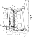
- a machine frame in the reeling end is designated 1.
- two cylinders 2, 3 are mounted in bearings 4, 5 on two bases 6, 7, which form foundation blocks for a pair of gables 8, 9 in the machine frame 1.
- a transversal beam 10 extends between and connect the upper portions of gables 8, 9.
- a number of web rolls 11 which have different width and whose ends 50, Fig. 3 , shall be secured, rest on the cylinders 2, 3.
- the cylinders 2, 3 are provided such that they can be rotated, conveniently by means of a motor 20 for each cylinder.
- the size of the tape in the example will yet be the same as the size of the tapes which conventionally are used in the field, i.e. 50 x 250 mm. However it is possible according to the invention, if that would be desired, to produce also wider tapes, e.g. tapes with the size 100 x 250 mm, simply by cutting off a 100 mm long piece of tape from the roll of adhesive tape 15.
- the dispenser 13 can be moved in the vertical direction by means of motion means, generally designated 19, which may be of a conventional type, between an upper working position, Fig.
- the tape has an adhering coating only on that side which shall face those end portions of web material which shall be secured. If the web material is paper, the tape also consists of paper or other material which can be dissolved in connection with recycling in a paper mill. In other cases, the tape is made of a material suitable in the case.
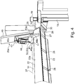
- the box girder 22 has a perforated bottom 26, Fig. 6 , and one of its ends, defined as the front end, 27, Fig. 1 , Fig. 4 , extends to nearly close to the dispenser 13, separated from the dispenser only by a short gap 29, Fig. 4 .
- Fig. 1 - Fig. 4 shows the box girder in its loading position, that is in the position where it receives tapes 28 from the dispenser 13 at the same level as where the dispenser is located and is oriented such that a slot-shaped feeding out opening 30 in the dispenser 13 is on the same level as the bottom surface of the conveyor belt 23, Fig. 3 , Fig. 4 .
- the driving motor 24 for the conveyor belt 23 is provided at the rear end of the box girder and drives the conveyor belt via a not shown driving roll in a chamber 31 in said rear end.
- Said chamber 31 is separated by a partition wall 32 (indicated by dashed lines on the exterior of the box girder) from the main part of the box girder, where said perforated bottom is located.
- the conveyor belt's driving roll in the chamber 31 may be coated with friction rubber, or may other conventional or specially designed means be provided in order to ensure a safe grip against the conveyor belt and hence a non-slip coupling between the driving roll and the conveyor belt.
- the driving motor 24 may be provided in or outside the chamber 31, as well as not shown means for maintaining the conveyor belt stretched. In the drawings, however, the driving motor 24 is placed on the outside.
- the one set of motion members 25a, Fig. 1 now will be described with reference to Fig.5 in a view from below to the left in Fig. 1 .
- the second set of motion members 25a is identically but mirrorwise designed.
- the box girder 22, which constitutes the framework of the conveyor 14, and the conveyor belt are shown cut off in the drawing.
- the motion members include an elongated, wide and plate-shaped slide 40 which extends obliquely upwards-downwards at the same angle of inclination as the intended direction of movement of the conveyor 14 to and fro the web rolls 11.
- One side 40a of the slide 40 is flat and faces the corresponding slide in the second set of motion members 25b.
- slide 40 On the opposite side 40b of slide 40 there are provided two pairs of parallel recesses or grooves 41a' and 41a", and 41b' and 41b", respectively, which match two pairs of corresponding rails 42a' and 42a", and 42b' and 42b", respectively, on a guide 38.
- the two pairs of rails on the guide 38 clutch the two rail- shaped male portions 42" and 42''' which are formed between the grooves 41a' and 41a", and 41b' and 41b", respectively, on the slide.
- the guide 38 is fixedly mounted on, or forms an integrated part of a bracket 38a, which is fixedly mounted on the machine frame 1.
- Driving means in said members 25a consist of an electrical motor 45 mounted on the bracket 38a, and a toothed drive belt 45a, which extends about half the circumference of a toothed drive wheel 45b on the driving axis of the motor 45, the teeth of which match the teeth of the drive belt 45 a.
- the toothed drive belt 45a extends along the whole length of the guide 40. It is recessed in a central groove in the guide and is fastened in the two ends of the guide.
- the bracket 38a and the motor 45 are protected by a cover 39, which has been removed in Fig. 5 in order to visualize the driving members under the cover.
- the ruler/rulers is/are provided simultaneously to be moved down against a portion 28a of the tapes 28 which extends beyond the rear edge of the box girder 22, and for a fraction of a second press that portion 28a against the web rolls, so that the tapes initially stick with their adhesive underside to the web material, whereupon the ruler/rulers are brought back to their resting position as shown in Fig.6 .
- a number of pneumatic actuators 56b are provided for the movements of the ruler/rulers, suspended by and connected via hinges/hangers 58 which extend downwards from an elongated, horizontal carrier 59 which is secured on the rear side 22b of the box girder 22.
- the further devices 57 which shall complete the application and also minimize formation of wrinkles in connection with the application, include a series of rolls 57a. Said rolls are carried by bent arms 57b, which are pivotally connected to the same hangers 58 which carry the said first devices 56, and are pressed by means of springs 57c against the web rolls 11 and successively also against the tapes and the web ends 50.
- the box girder 22 may have a considerable length. In the case when the invention shall be applied in the paper manufacturing industry, the length may exceed ten meters. In order to prevent any unacceptably large deflection, the box girder therefor should have a low dead weight and an adequate bending rigidity, particularly in the vertical direction. It may also be reinforced by an exterior or, as is shown in Fig. 6 , by an interior, perforated framework 60.
- the process for the manufacturing of paper is computerized to a high degree. This is true also as far as those units are concerned, which are provided in direct connection to the reeling end or the slitting and winding machine.
- the control unit which is responsible for controlling the automatic application of the tapes.
- information is stored about the diameter of the rolls 11 of paper/web material, the width of each of them, how many tapes that shall be attached on each of them, where the tapes shall be placed, and the distance between them.
- the process for securing the ends of the paper web on the finished rolls is initiated already when the paper is being processed in the reeling end or in the slitting and winding machine of the paper manufacturing machine.
- the tape dispenser 13 and the tape conveyor 14 then are in their charging positions far above the levels which the finished rolls later on shall occupy, Fig. 1 , Fig. 3 .
- the conveyor belt 23 is moved at a low, constant rate about the box girder 22 during this phase.
- a pulse transducer transmits a signal to the electromagnetically operated cutter in the tape dispenser 13 to cut off a piece of tape from the roll of adhesive tape 15, such as the tape 28a, Fig.
- the tape conveyor 14 with the on its underside releasably adhering tapes is moved obliquely downwards towards the web ends 50 on the rolls 11, more specifically towards the edges 52 of said ends 50, by means of the motion members 25a and 25b.
- the tape conveyor 14 now has been brought to the position illustrated in Fig. 6 .
- the ruler/rulers 56a then are quickly brought down against the sticking out portions 28a of the tapes 28 until contact with the roller 11 at a distance inside the edge 52 of the web ends 50, causing the projecting portions 28a of all the tapes to contact its respective web end 50 simultaneously, whereupon they are quickly returned.
- the web rolls 11 then are rotated in the clock- wise direction with reference to Fig. 6 . The direction is also indicated by an arrow in the drawing.
- the tape dispenser 13 which is employed in the above described example contains a roll of adhering tape 15 which represents a large volume of tapes. But even that volume is eventually ended and has to be replaced, which is illustrated in Fig. 8 .
- the dispenser 13 thus is moved down by means of an elevator 19 from its upper working position, Fig. 1 , to the lower tape charging position at a level above the floor which is a comfortable working level for the staff who shall do that job.
- the elevator 19 can be designed in numerous ways according to conventional technique, i.e. as a screw conveyor, or by means of elements similar to those which are employed in the aggregate of motion members 25a, 25b for the linear movements of conveyor 14/box girder 22, and shall not be described more in detail. In the lower position a quick change of tape roll can be done, whereupon the dispenser 13 is lifted up to its working position.
Landscapes
- Replacement Of Web Rolls (AREA)
Description
- The present invention relates to a method for securing on each of a plurality of web rolls in a set of web rolls which lie close to or are adjacent to one another and have a common center axis, the trailing end of the web through applying on each of the rolls at least one securing tape which has an adhering coating on a first side, so that the end securing tape is fixed by said first side against the roll and extends over the edge (52) of the trailing end of the web. The invention also relates to an assembly of cooperating devices for the carrying out of the method.
- Various methods and devices are employed today for securing the ends of web rolls, manual as well as automatized. In the paper industry glue, for example, is used for securing the ends. This is fairly easy to automatize. Glue which provides a quick and safe connection, however, impairs the quality of the paper in the top layers of the roll. Therefore, the roll has to be stripped and one or a few layers be rejected before the paper can be used for example in printing machines. In order to avoid that problem, it is therefore common practice to use tape for securing the ends. The tapes are either applied manually, which is uneconomical and troublesome, or are they applied mechanically according any of a number of systems which have been developed in this technical field. Also these systems, however, have drawbacks of various kinds. Within for example the paper manufacturing industry, the paper is normally made in the form of a web material which has a large width and is wound up in a reeling unit provided after the paper machine or is slit up into a number of smaller rolls in a slitting and winding machine provided after the paper machine. For the mechanical securing of the trailing ends of the web it is common practice to employ a great number of so called tape dispensers - normally at least two dispensers per web roll - in order safely to secure the ends of all those rolls which lie axially side by side in the reeling end or in the slitting and winding machine. Further, the tape dispensers have to be mounted on a common carrier at a distance from one another. These distances must correspond to the desired distances between the tapes on the secured roll ends. All the tapes are drawn out simultaneously from the tape dispensers, are cut off and are secured over the web ends. This part is per se rational and can be performed quickly and automatically, but the fact problem that all the web rolls in the set of rolls often do not have equal widths is a problem. Further, the web sometimes are slot up to different widths and thence to different lengths of the rolls from set to set and sometimes even in one and the same set. The tape dispensers therefor must be re-mounted, such that the desired distance between the tapes will be achieved for every set of rolls. These adjustments are difficult to automatize and are therefore carried out manually, which is troublesome and uneconomical. Further the tape strips seldom are equally long, which means that the strips in the dispensers run out and have to be replaced at different occasions, which is also troublesome, time consuming, uneconomical and difficult or impossible to automatize in practice.
In publicationJP 2008 063044 A - Additionally document
JP2001206623
It is an object of the present invention to address the above complex of problems. This and other objects can be achieved therein that the invention is characterized by what is stated the appending claims.
Through the invention it will be possible to allocate the tapes with great accuracy completely digitally at desired places on the web rolls. In principle an infinitely variable allocation can be achieved. According to the invention it is also possible to choose a desired size of the tapes digitally in the axial direction of the web rolls. An adjustable pattern of the tapes which shall be distributed on the web rolls can be achieved without any physical readjustment of tape dispensers. According to one aspect of the invention, only a single tape dispenser is employed, but on the other hand, according to a preferred embodiment of the invention, the width of the tape strip in that dispenser is substantially wider than the width of the tape strips in those tape dispensers which conventionally are used according to the conventional technique. As a matter of fact, the width may be as large as the length of those tapes is, which are torn off from the conventional tape dispensers which are used in conventional systems for securing the ends of web rolls in the paper manufacturing industry. A single roll of tape of the said kind, which may be used according to the invention, therefore represents an amount of tapes which corresponds to quite a number of tape rolls of the type used in conventional systems. When this single but large tape roll is used up, it may, according to an aspect of the invention, be replaced by a new, equal roll of tape, while the web material is being wound up in the reeling end of the paper making machine or in a slitting and winding machine. The change of a roll of adhesive tape therefore does not cause any loss of production.
The invention is developed for the purpose of satisfying demands in the paper manufacturing industry, but its field of use is not restricted to that field. Its principles can be applied within many branches where web materials are manufactured, treated, converted and/or used, whether they consist of paper, paper board, non-woven material, plastic, aluminum foils, composite materials, or any other material which can be reeled to the shape of rolls, the trailing ends of which shall be secured by means of adhering tapes.
These and other advantages can, according to one aspect of the invention, be achieved therein that those end securing tapes which shall be applied first are transferred from a tape dispenser to a tape conveyor such that they are caused to lie with their opposite, second side against said conveyor at a distance from one another on the conveyor corresponding to the desired distances between the securing tapes on the web rolls, respectively, that they are temporarily retained on the conveyor as the conveyor then is moved towards the web rolls with the adhering first side facing the web rolls each tape being directed against that place on the rolls where the respective tape shall be applied, that all the tapes are brought into contact with their respective roll and are fixed to it on said respective place, and that the conveyor then is moved from the rolls and from the tapes, which remain fixed to the rolls because said first side of the tapes has a larger adhesive strength to the rolls than the opposite, second side has to the conveyor. - According to another aspect of the invention, there is employed, for the carrying out of the method, an assembly of cooperating devices, which include a tape dispenser provided to feed tapes one by one to an essentially rigid, elongated tape conveyor which has a length at least as long as the distance between the farthest out positioned tapes that shall be applied against the rolls means provided for placing the tapes on the conveyor with a spacing corresponding with the desired spacing between the tapes when the tapes have been secured on desired places on the web rolls wherein the conveyor is capable of retaining the tapes when the tapes rest with their second side against the conveyor, which second side is opposite said first side, and wherein a first aggregate of motion members is provided to move the conveyor with said tapes towards said desired places on the web rolls from a starting position at a distance from the web rolls till contact between said first side of the tapes and the rolls on said desired places and then back to the starting position, leaving the tapes behind, secured on said desired places on the web rolls. Preferably, the tapes which are used in the method and in the assembly have an adhering coating only on that side which shall be attached to the web rolls in order to secure their ends. In principle, however, both sides may have adhering coatings. The method and the assembly then are adapted to this circumstance. For example, the surface of the conveyor against which the tapes temporarily shall be brought, in that case may have been afforded features which prevent non-desired adherence, i.e. have release-features. It is, however, understood that this is a complication which can be avoided by using tapes which have an adhering coating on one side only. A conceivable variant also is to use tapes which have a certain amount of, but essentially lower, adhering capacity on that side which shall be brought against the conveyor surface than the tapes have on that opposite side which shall be brought into contact with the rolls of web material. Further aspects on, and advantages of the invention, will be apparent from the following description of a preferred embodiment with reference to the accompanying drawings.
- In the following description of a preferred embodiment, reference will be made to the accompanying drawings, in which
-
Fig.1 is a perspective view of the rolls of web material, the free or trailing ends of which shall be secured, and the assembly according a preferred embodiment of the invention, which forms part of a slitting machine or reeling end which may be provided in connection to a paper manufacturing machine, -
Fig. 2 shows the assembly isolated in the same view as inFig. 1 , -
Fig. 3 shows the assembly according to the invention in a view diametrically opposed to the view ofFig. 2 , -
Fig.4 illustrates, at a larger scale, how a tape dispenser is delivering tapes to a tape conveyor included in the assembly, in the following briefly also called just conveyor, -
Fig.5 shows, also at a larger scale, motion members for moving the conveyor in a linear direction towards and from the web rolls, -
Fig. 6 shows in the same perspective asFig. 1 a developed embodiment of the conveyor in cross section and motion members for turning the conveyor about a longitudinal centre axis in the final part of the initial application of the tapes on the rolls, -
Fig. 7 shows the conveyor in its lower position in the final part of the application operation, and -
Fig.8 illustrates a method and means which facilitates change of tape dispenser. - Modern paper manufacturing machines are immensely large machines which at a high rate produce large width paper, which first is wound up to form a so called tambour. When the tambour has reached a size which is considered to be conveniently large, which may correspond to a weight of many tens of tons, the tambour is lifted up from the paper making machine and is transferred to a slitting and winding machine or to a reeling end, where it is subjected to slitting and cutting to rolls with a roll width and a web length according to the customer's specifications. The example of an embodiment of the invention which shall be described in detail in the following concerns how the trailing ends of the web rolls in such a reeling end or slitting and winding machine are secured.
- With reference first to
Fig. 1 , a machine frame in the reeling end is designated 1. In the reeling end, twocylinders bearings bases gables transversal beam 10 extends between and connect the upper portions ofgables Fig. 3 , shall be secured, rest on thecylinders cylinders motor 20 for each cylinder. In the reeling end, or in the slitting and winding machine, as the case may be, also a number of further means, which normally are included in such machines, may be included, such as means for slitting and cutting the web, means for moving the finished, end secured rolls out from the reeling end or slitting and winding machine, etc. - The integrated assembly according to the invention is generally designated 12,
Fig. 2 . Its main components consist of atape dispenser 13, atape conveyor 14, and motion means for the conveyor. Thetape dispenser 13 is of a type and has a design which is known per se, but is not of the type and design which conventionally is employed in the present field of use. The main difference is that the roll ofadhesive tape 15 in thedispenser 13 is much wider than those tape rolls which conventionally are used in the field. While the latter ones normally have a width in the order of 50 mm, the roll ofadhesive tape 15 in the dispenser is several times wider. In the present example it has a width of 250 mm. On the other hand, an essentially shorter piece of tape is cut off in connection with each delivery of tape, e.g. 50 mm, than what is conventional, by means of an electromagnetically operated cutter, not shown, which is provided in thedispenser 13. The size of the tape in the example will yet be the same as the size of the tapes which conventionally are used in the field, i.e. 50 x 250 mm. However it is possible according to the invention, if that would be desired, to produce also wider tapes, e.g. tapes with the size 100 x 250 mm, simply by cutting off a 100 mm long piece of tape from the roll ofadhesive tape 15. In or on thedispenser 13 there is also anelectric motor 18, which is shown symbolically, for feeding out tape. Thedispenser 13 can be moved in the vertical direction by means of motion means, generally designated 19, which may be of a conventional type, between an upper working position,Fig. 1 - Fig. 5 , and a lower charging position,Fig. 8 , which need to be visited more seldom, for replenishment of tape. The tape has an adhering coating only on that side which shall face those end portions of web material which shall be secured. If the web material is paper, the tape also consists of paper or other material which can be dissolved in connection with recycling in a paper mill. In other cases, the tape is made of a material suitable in the case. - The main parts of the
conveyor 14 consist of anelongated box girder 22, an endless conveyingbelt 23 extending about the two ends of the box girder, a driving motor 24 (symbolically shown), for the conveying belt, two sets ofaggregates rotation 37. That side of thebox girder 22 which inFig. 3 and inFig. 4 is facing the viewer is denominatedfront side 22a, and its opposite side,Fig. 1 ,Fig. 2 , andFig. 5 , consequently denominatedrear side 22b. The motion means 25a and 25b for the linear movements of the conveyor are shown only schematically inFig. 1 ,Fig. 7 and inFig. 8 . Their design is shown more in detail inFig. 5 . - The
box girder 22 has a perforated bottom 26,Fig. 6 , and one of its ends, defined as the front end, 27,Fig. 1 ,Fig. 4 , extends to nearly close to thedispenser 13, separated from the dispenser only by ashort gap 29,Fig. 4 .Fig. 1 - Fig. 4 shows the box girder in its loading position, that is in the position where it receivestapes 28 from thedispenser 13 at the same level as where the dispenser is located and is oriented such that a slot-shaped feeding out opening 30 in thedispenser 13 is on the same level as the bottom surface of theconveyor belt 23,Fig. 3 ,Fig. 4 . The drivingmotor 24 for theconveyor belt 23 is provided at the rear end of the box girder and drives the conveyor belt via a not shown driving roll in achamber 31 in said rear end. Saidchamber 31 is separated by a partition wall 32 (indicated by dashed lines on the exterior of the box girder) from the main part of the box girder, where said perforated bottom is located. The conveyor belt's driving roll in thechamber 31 may be coated with friction rubber, or may other conventional or specially designed means be provided in order to ensure a safe grip against the conveyor belt and hence a non-slip coupling between the driving roll and the conveyor belt. The drivingmotor 24 may be provided in or outside thechamber 31, as well as not shown means for maintaining the conveyor belt stretched. In the drawings, however, the drivingmotor 24 is placed on the outside. - The interior 35 of the box girder has, as mentioned, a perforated bottom 26 in the region of the main part of the box girder which extends from the partition wall 32, and is connected to a symbolically shown
air exhauster 34 via a symbolically shownhose 33, -
Fig. 6 , such that a reduced pressure is maintained in the box girder above theperforated bottom 26. Theconveyor belt 23 consists of a high strength material which is permeable to air. It may for example consist of a belt which is perforated by holes lying closely together and is preferably reinforced such that it will have such a high coefficient of elasticity in the longitudinal direction of the belt, such that its elongation can be neglected. When the interior 35 of thebox girder 22 is connected to theair exhauster 34, air will therefore be sucked in into the interior of the box girder via the airpermeable conveyor belt 23 and theperforated bottom 26 of the box girder. This is employed for suctioning fast thetapes 28 with their non-adhesive side against theconveyor belt 23, as will be further described in the following. - The one set of
motion members 25a,Fig. 1 , now will be described with reference toFig.5 in a view from below to the left inFig. 1 . The second set ofmotion members 25a is identically but mirrorwise designed. Thebox girder 22, which constitutes the framework of theconveyor 14, and the conveyor belt are shown cut off in the drawing. The motion members include an elongated, wide and plate-shapedslide 40 which extends obliquely upwards-downwards at the same angle of inclination as the intended direction of movement of theconveyor 14 to and fro the web rolls 11. Oneside 40a of theslide 40 is flat and faces the corresponding slide in the second set ofmotion members 25b. On theopposite side 40b ofslide 40 there are provided two pairs of parallel recesses orgrooves 41a' and 41a", and 41b' and 41b", respectively, which match two pairs of correspondingrails 42a' and 42a", and 42b' and 42b", respectively, on aguide 38. The two pairs of rails on theguide 38 clutch the two rail- shaped male portions 42" and 42''' which are formed between thegrooves 41a' and 41a", and 41b' and 41b", respectively, on the slide. Theguide 38 is fixedly mounted on, or forms an integrated part of abracket 38a, which is fixedly mounted on the machine frame 1. - Driving means in said
members 25a consist of anelectrical motor 45 mounted on thebracket 38a, and atoothed drive belt 45a, which extends about half the circumference of atoothed drive wheel 45b on the driving axis of themotor 45, the teeth of which match the teeth of thedrive belt 45 a. Thetoothed drive belt 45a extends along the whole length of theguide 40. It is recessed in a central groove in the guide and is fastened in the two ends of the guide. Thebracket 38a and themotor 45 are protected by acover 39, which has been removed inFig. 5 in order to visualize the driving members under the cover. - The
conveyor 14 is connected to the lower ends of the twoguides 40, in a mode which is partly illustrated inFig. 5 but will be shown and explained more in detail in the following. But it should be understood already by what has been shown and explained so far, that the twoslides 40, which form part of saidsets guides 38, can be displaced through linear movements, bringing theconveyor 14 with them, to and fro the web rolls by means of the stationary mounted motors 45 (one in each set ofmotion members toothed drive belts 45 a. - Each
set Fig 3 ,Fig. 4 andFig. 6 , for turning thebox girder 22 about a horizontal axis ofrotation 37, comprises the following components in each end of the conveyor 14: apneumatic actuator 44, abracket 43 which is stationary mounted on the flat side of 40a of theslide 40, and ashort lever 46a in the form of a first arm of a right-angled yoke 46, thesecond arm 46b of which is secured to thefront side 22a of the box girder. The first mentioned arm/lever 46a extends over the upper side of the box girder at a short distance therefrom, such thatpassages 51 are formed for theconveyor belt 23 between the arms/levers 46a and thebox girder 22.Nose portions 47 of thelevers 46a in both ends of the box girder extend a distance beyond therear side 22b of the box girder. - An axle bar 53 has a
first part 53a which has a large diameter and a second part 53b which has a smaller diameter. Thefirst part 53a of the axle bar is stationary connected to the flat side of theslide 40, while thelevers 46a in the two ends are pivotally connected to the second part 53b of the respective axle bar 53 in afirst hole 48 which forms a bearing in the yoke 46 in a region above thefront wall 22a of the box girder. The center of the axle bar 53 defines said center ofrotation 37. In the projecting nose portion of thelever 46a, asecond hole 49 is provided for the connection of the piston rod of the actuator 56b to thelever 46a. -
Fig. 6 shows a development of the invention which aims at making the application of thetapes 28 on the web rolls 11 more efficient. For that purpose, according to the embodiment, the tape conveyor is equipped withfirst devices 56 for causing an initial application of thetapes 28, andsecond devices 57 for completing the application. These devices are placed on therear side 22b of thebox girder 22. The first devices include a ruler or a series ofrulers 56a, which consist of a metal rail having a thick layer of a plastic material with a low friction coefficient, e.g. Teflon, on its underside. The ruler/rulers 56a extends/extend along the entire part of thebox girder 22 which is provided with a perforated bottom. The ruler/rulers is/are provided simultaneously to be moved down against a portion 28a of thetapes 28 which extends beyond the rear edge of thebox girder 22, and for a fraction of a second press that portion 28a against the web rolls, so that the tapes initially stick with their adhesive underside to the web material, whereupon the ruler/rulers are brought back to their resting position as shown inFig.6 . A number ofpneumatic actuators 56b are provided for the movements of the ruler/rulers, suspended by and connected via hinges/hangers 58 which extend downwards from an elongated,horizontal carrier 59 which is secured on therear side 22b of thebox girder 22. Thefurther devices 57, which shall complete the application and also minimize formation of wrinkles in connection with the application, include a series of rolls 57a. Said rolls are carried bybent arms 57b, which are pivotally connected to thesame hangers 58 which carry the saidfirst devices 56, and are pressed by means ofsprings 57c against the web rolls 11 and successively also against the tapes and the web ends 50. - The
box girder 22 may have a considerable length. In the case when the invention shall be applied in the paper manufacturing industry, the length may exceed ten meters. In order to prevent any unacceptably large deflection, the box girder therefor should have a low dead weight and an adequate bending rigidity, particularly in the vertical direction. It may also be reinforced by an exterior or, as is shown inFig. 6 , by an interior,perforated framework 60. - The mode according to which the assembly of the invention is intended to operate, can be automatized to a high degree. This is particularly true as far the paper manufacturing industry is concerned, the specific demands of which the application in the first place has been developed to satisfy. Within other fields of use, the demand of automatization may not be correspondingly great, or is a high degree of automatization not possible or even desirable, but also in those fields of use the invention may hold out many advantages in connection with manufacturing and/or winding up web material, even if not as obvious as within the paper manufacturing industry. In the following, however, the mode of operation of the invention shall be described as an example of the highly automatized technique which the invention makes possible for securing the ends of web rolls in the paper manufacturing industry.
- The process for the manufacturing of paper is computerized to a high degree. This is true also as far as those units are concerned, which are provided in direct connection to the reeling end or the slitting and winding machine. When the web material has been cut and slot and the paper rolls 11 are resting on the
cylinders rolls 11 of paper/web material, the width of each of them, how many tapes that shall be attached on each of them, where the tapes shall be placed, and the distance between them. - The process for securing the ends of the paper web on the finished rolls is initiated already when the paper is being processed in the reeling end or in the slitting and winding machine of the paper manufacturing machine. The
tape dispenser 13 and thetape conveyor 14 then are in their charging positions far above the levels which the finished rolls later on shall occupy,Fig. 1 ,Fig. 3 . Theconveyor belt 23 is moved at a low, constant rate about thebox girder 22 during this phase. At times determined according to data which are stored in the control unit for that specific set of web rolls which is being manufactured, a pulse transducer transmits a signal to the electromagnetically operated cutter in thetape dispenser 13 to cut off a piece of tape from the roll ofadhesive tape 15, such as the tape 28a,Fig. 4 , which immediately is fed out through the slot shaped feeding-outopening 30,Fig. 4 , which is essentially at level with the bottom surface of theconveyor belt 23, and from there the tape is directed out under theconveyor belt 23. Then the tape 28a, due to the reduced pressure in thebox girder 22 is immediately sucked fast, while the tapes which previously have been fed out, are maintained sucked fast against underside of the airpermeable conveyor belt 23, which is in contact with symbolically shownvacuum source 34. In this mode a desired number oftapes 28 are successively distributed to the underside of conveyor belt,Fig. 3 , on places which correspond to those places on the finished web rolls 11 in the reeling end 1 where the tapes shall be attached,Fig. 4 , whereupon the conveyor belt is stopped. - When the paper, or other web material, of a desired length has been manufactured, has been slot to desired widths, and in the form of rolls have been placed on the
cylinders tapes 28 which have been distributed in the said desired way on theconveyor belt 23. Information is also stored about where the end of the web material is located, when the tape application process is initiated, as well as information about where the end should be located when the tapes are applied. If the actual is- value does not correspond with the desired should-value, therolls 11 are rotated a certain angle on therolls motors 20 until the desired should- value, which is stored in the control unit, has been reached. - Simultaneously, or when the position of the web ends have been adjusted, the
tape conveyor 14 with the on its underside releasably adhering tapes is moved obliquely downwards towards the web ends 50 on therolls 11, more specifically towards theedges 52 of said ends 50, by means of themotion members - Simultaneously, or when the underside of the tape conveyor has reached a position close to the rolls, the
tape conveyor 14, if necessary, is turned about its horizontal axis ofrotation 37 by means of the aggregation ofmotion members rolls 11, so that the underside of theconveyor belt 23 will be essentially parallel with a tangent to therolls 11 where the tapes shall be placed. - The
tape conveyor 14 now has been brought to the position illustrated inFig. 6 . The ruler/rulers 56a then are quickly brought down against the sticking out portions 28a of thetapes 28 until contact with theroller 11 at a distance inside theedge 52 of the web ends 50, causing the projecting portions 28a of all the tapes to contact itsrespective web end 50 simultaneously, whereupon they are quickly returned. When the adhering surface of the projecting portion of the tapes contacted the web ends, they were immediately adhered to them. The web rolls 11 then are rotated in the clock- wise direction with reference toFig. 6 . The direction is also indicated by an arrow in the drawing. As therolls 57a are rolled over the adhering portions 28a and successively also over the rest of the tapes, at the same time as therolls 57a are pressed against thetapes 28 by means of thesprings 57c,efficient adherence between the whole adhering surface of the tapes is achieved. At the same time also possible wrinkles are eliminated. The application of the tapes thence is finished and all components of the assembly may be returned to their starting positions,Fig. 1 . - The
tape dispenser 13 which is employed in the above described example contains a roll of adheringtape 15 which represents a large volume of tapes. But even that volume is eventually ended and has to be replaced, which is illustrated inFig. 8 . Thedispenser 13 thus is moved down by means of anelevator 19 from its upper working position,Fig. 1 , to the lower tape charging position at a level above the floor which is a comfortable working level for the staff who shall do that job. Theelevator 19 can be designed in numerous ways according to conventional technique, i.e. as a screw conveyor, or by means of elements similar to those which are employed in the aggregate ofmotion members conveyor 14/box girder 22, and shall not be described more in detail. In the lower position a quick change of tape roll can be done, whereupon thedispenser 13 is lifted up to its working position. - Due to the design of the assembly, the invention is well adapted to a high degree of automatizing, which is illustrated by the above description. As mentioned in the preamble, however, there are applications where a high degree of automatizing is neither possible nor desired. In such cases the basic principles of the invention can be combined with measures which can performed manually. The invention and the claimed patent protection is therefore not restricted to the application which is described in the example, but only by the patent claims.
Claims (15)
- A method for securing on each of a plurality of web rolls in a set of web rolls which lie close to or are adjacent to one another and have a common centre axis, the trailing end (50) of the web through applying on each of the rolls at least one securing tape (28) which has an adhering coating on a first side, so that the end securing tape is fixed with said first side against the roll and extends over the edge (52) of the trailing end of the web,
characterized in that those end securing tapes (28) which shall be applied, first are transferred from a tape dispenser (13) to a tape conveyor (14,22) such that they are caused to lie with their opposite, second side against said conveyor at a distance from one another on the conveyor corresponding to the desired distances between the securing tapes on the web rolls, respectively, that they are temporarily retained on the conveyor as the conveyor thereafter is moved towards the web rolls with the adhering first side (28b) facing the web rolls, each tape being directed against that place on the rolls where the respective tape shall be applied, that all the tapes are brought into contact with their respective roll and are fixed to it on said respective place, and that the conveyor then is moved from the rolls and from the tapes, which remain fixed to the rolls therein that said first side of the tapes has a larger adhesive strength to the rolls than the opposite, second side has to the conveyor. - A method according to claim 1, characterized in that the tapes (28) have an adhesive coating only on said first side and that they temporarily are retained by suction power against the conveyor.
- A method according to claim 1 or 2, characterized in that the tapes temporarily are retained against a conveying belt (23) on the conveyor.
- A method according to claim 3, characterized in that the tapes are fed from a tape dispenser (13) to the conveyor, that they are distributed on the conveyor belt at a distance from one another corresponding to the desired distances between the tapes when they have been applied on the web rolls, that the conveyor provided with said tapes is moved towards the web rolls until contact between the adhering surfaces of the tapes and the web rolls on intended places so that the tapes will cover the end edges (52) of the webs, and that the conveyor then is moved away from the web rolls, leaving the tapes behind, securing the web ends.
- A method according to any of claims 1-4, characterized in that the tapes are cut off from a tape roll in said tape dispenser such that their length crosswise to the longitudinal direction of the tape web in the tape roll is caused to be longer that the length of the tape in the outflow direction of the tape web from the dispenser.
- A method according to any of claims 1-5, characterized in that the tapes are distributed along the conveyor by means of the movable conveyor belt, that they are stuck fast through suction against the conveyor belt because the conveyor belt is pervious to air and contacts a wall of the conveyor which is perforated, and because an underpressure is maintained in the interior (35) of the conveyor inside of said perforated wall.
- A method according to any of claims 1-6, characterized in that the tapes are transferred from the tape dispenser to the conveyor such that a portion (28a) of the tapes extends beyond a rear side (22b) of the conveyor.
- A method according to claim 7, characterized in that said extending portion (28a) of each tape initially is brought into contact with said trailing end/ends (50) at a distance from the edge (52) of the trailing end, and that the rest of the tapes thereafter successively are pressed against the web.
- An assembly for securing on each of a plurality of web rolls in a set of web rolls which lie close to or adjacent to one another and have a common centre axis, the trailing end (50) of the web through applying on each of the rolls at least one securing tape (28) and totally a plurality of tapes which have an adhering coating on a first side, and applying the tapes with said first side against the rolls such that they extend over the edge of the web end,
characterized in that it comprises a tape dispenser (13) provided to feed tapes one by one to an essentially rigid, elongated tape conveyor (14) which has a length at least as long as the distance between the farthest out positioned tapes that shall be applied against the rolls, that means (23) are provided for placing the tapes on the conveyor with a spacing corresponding with the desired spacing between the tapes when the tapes have been secured on desired places on the web rolls, that the conveyor is capable of retaining the tapes when the tapes rest with their second side against the conveyor, which second side is opposite said first side, and that a first aggregate of motion members (25a,25b) is provided to move the conveyor with said tapes towards said desired places on the web rolls from a starting position at a distance from the web rolls till contact between said first side of the tapes and the rolls on said desired places and then back to the starting position leaving the tapes behind, secured on said desired places on the web rolls. - An assembly according to claim 9, characterized in that the conveyor (14) has a movable conveyor belt.
- An assembly according to claim 10, characterized in that the interior of the box girder (22) is connected to a vacuum source (34) in order to maintain an underpressure (pressure below that of the atmosphere) in the interior of the box girder, that the box girder has a perforated bottom (26), that the conveyor belt is permeable to air and that it directly or indirectly contacts said perforated girder bottom such that the tapes can be held by suction power against the conveyor belt.
- An assembly according to claim 10, characterized in that the conveyor body comprises a box girder (22), that the conveyor belt is endless and movable around the box girder, that the conveyor has a first end adjacent to the tape dispenser, and that an out feeding opening (30) for tapes is essentially at level with an outside of the conveyor belt, preferably with its underside, when the conveyor and the tape dispenser are in their feeding out position.
- An assembly according to claim 9, characterized in that a second aggregation of motion members (36a,36b) are provided for turning the conveyor (14) about a horizontal axis of rotation (37).
- An assembly according to claim 9, characterized in that at least any of the following means are provided on the rear side of the conveyor, namely any of the means which include means (56) for initially pressing against the web rolls a tape portion (28a) which extends beyond said rear side, and means for successively pressing the rest of the tapes against the web material.
- An assembly according to any of claims 9-14, characterized in that, during the feeding out of tapes from the tape dispenser to the conveyor, the tape dispenser and the conveyor are located at an essentially higher level than those web rolls which shall be coated with said tapes, and that said first aggregate of motion members (25a,25b) for the provision of the linear movements of the conveyor are provided to displace the conveyor down from and up to said higher level.
Applications Claiming Priority (3)
| Application Number | Priority Date | Filing Date | Title |
|---|---|---|---|
| SE1350851 | 2013-07-08 | ||
| SE1350865 | 2013-07-11 | ||
| PCT/SE2014/050675 WO2015005843A1 (en) | 2013-07-08 | 2014-06-03 | Method and assembly for securing the end of a web roll |
Publications (3)
| Publication Number | Publication Date |
|---|---|
| EP3022143A1 EP3022143A1 (en) | 2016-05-25 |
| EP3022143A4 EP3022143A4 (en) | 2017-09-20 |
| EP3022143B1 true EP3022143B1 (en) | 2018-10-03 |
Family
ID=52280741
Family Applications (1)
| Application Number | Title | Priority Date | Filing Date |
|---|---|---|---|
| EP14823505.4A Active EP3022143B1 (en) | 2013-07-08 | 2014-06-03 | Method and assembly for securing the end of a web roll |
Country Status (2)
| Country | Link |
|---|---|
| EP (1) | EP3022143B1 (en) |
| WO (1) | WO2015005843A1 (en) |
Families Citing this family (2)
| Publication number | Priority date | Publication date | Assignee | Title |
|---|---|---|---|---|
| FI126888B (en) * | 2016-06-17 | 2017-07-14 | Valmet Technologies Oy | Method for attaching the end of a fiber web to a fiber web reel and fastener distribution system for securing the end of a fiber web to a fiber web reel adjacent to a roller cutting machine |
| CN109051933B (en) * | 2018-07-25 | 2020-06-12 | 广东溢达纺织有限公司 | Large package cloth dividing, labeling and sealing system and method |
Family Cites Families (7)
| Publication number | Priority date | Publication date | Assignee | Title |
|---|---|---|---|---|
| US3989582A (en) * | 1972-09-11 | 1976-11-02 | Imperial Oil Limited | Winding apparatus |
| JP2571151B2 (en) * | 1990-11-22 | 1997-01-16 | 富士写真フイルム株式会社 | Terminal stop tape supply device |
| JPH05116818A (en) * | 1991-10-24 | 1993-05-14 | Sumitomo Jukikai Valmet Kk | Winding device for winding moistureproof sheet around take-up roll, and winding method using the same |
| JP3887707B2 (en) * | 1998-05-07 | 2007-02-28 | 株式会社イソワ・フーパースイフト | Automatic tape pasting method and apparatus |
| JP3032759B1 (en) * | 1999-03-31 | 2000-04-17 | 株式会社東京機械製作所 | Tab for fixing the web end |
| JP2001206623A (en) * | 2000-01-28 | 2001-07-31 | Sumitomo Heavy Ind Ltd | End tape sticking device |
| JP4743051B2 (en) * | 2006-09-05 | 2011-08-10 | 川上産業株式会社 | APPARATUS AND METHOD FOR TAPEING TERMINAL OF COIL OF SHEET |
-
2014
- 2014-06-03 WO PCT/SE2014/050675 patent/WO2015005843A1/en active Application Filing
- 2014-06-03 EP EP14823505.4A patent/EP3022143B1/en active Active
Non-Patent Citations (1)
| Title |
|---|
| None * |
Also Published As
| Publication number | Publication date |
|---|---|
| WO2015005843A1 (en) | 2015-01-15 |
| EP3022143A1 (en) | 2016-05-25 |
| EP3022143A4 (en) | 2017-09-20 |
Similar Documents
| Publication | Publication Date | Title |
|---|---|---|
| KR102072742B1 (en) | Tensioning and loading system of rolled material in roll form | |
| KR102267908B1 (en) | Bead Wire Wrapper Apparatus and Wrapper Method | |
| US7972257B2 (en) | Article forming paper wrapping device | |
| CN110053806B (en) | Automatic parcel device for combined firework surrounding | |
| EP3090856A1 (en) | Forming machine for forming a hollow body, in particular a casing of a solid propellant engine, and deposit head for such a forming machine | |
| EP3022143B1 (en) | Method and assembly for securing the end of a web roll | |
| CA1239628A (en) | Sheet splicer | |
| CN110193993B (en) | Non-stop film laminating complete equipment | |
| CN107500015B (en) | Sponge sheet and double-sided tape laminating equipment | |
| CN211031192U (en) | Double-station feeding mechanism of automatic plastic sucking machine | |
| KR101707082B1 (en) | Apparatus for automatically supplying film for a wood pannel | |
| EP2100735A1 (en) | Device for supplying foil to be used in a printing process to a printing press | |
| US11472654B2 (en) | Feeding unit for a tissue converting machine for converting a web of two-layer tissue | |
| EP3828110A1 (en) | Rereeler and method for rereeling fiber webs | |
| JPH05302B2 (en) | ||
| JP2003276915A (en) | Automatically switching device for winding part | |
| CN209291672U (en) | Material devices for taking-up and tire liner production line | |
| JP2004244200A (en) | Method and device for removing defective portion of roll paper | |
| CN109230707B (en) | Packaging film connects membrane device | |
| US4707968A (en) | Method and apparatus for wrapping pressure sensitive rolls of material | |
| EP1545867B1 (en) | Apparatus for feeding paper webs and the like, for the production of cardboard tubes | |
| CN112060682B (en) | Lifting handle belt transferring, installing and leveling device of lifting handle installing machine and using method thereof | |
| EP4008529B1 (en) | Lamination head having bi-directional capability | |
| US1185447A (en) | Bias-cutter take-up. | |
| CN113120652A (en) | Automatic feeding machine |
Legal Events
| Date | Code | Title | Description |
|---|---|---|---|
| PUAI | Public reference made under article 153(3) epc to a published international application that has entered the european phase |
Free format text: ORIGINAL CODE: 0009012 |
|
| 17P | Request for examination filed |
Effective date: 20151221 |
|
| AK | Designated contracting states |
Kind code of ref document: A1 Designated state(s): AL AT BE BG CH CY CZ DE DK EE ES FI FR GB GR HR HU IE IS IT LI LT LU LV MC MK MT NL NO PL PT RO RS SE SI SK SM TR |
|
| AX | Request for extension of the european patent |
Extension state: BA ME |
|
| DAX | Request for extension of the european patent (deleted) | ||
| A4 | Supplementary search report drawn up and despatched |
Effective date: 20170821 |
|
| RIC1 | Information provided on ipc code assigned before grant |
Ipc: B65H 18/02 20060101ALI20170815BHEP Ipc: B65H 19/29 20060101AFI20170815BHEP |
|
| GRAP | Despatch of communication of intention to grant a patent |
Free format text: ORIGINAL CODE: EPIDOSNIGR1 |
|
| STAA | Information on the status of an ep patent application or granted ep patent |
Free format text: STATUS: GRANT OF PATENT IS INTENDED |
|
| INTG | Intention to grant announced |
Effective date: 20180515 |
|
| GRAS | Grant fee paid |
Free format text: ORIGINAL CODE: EPIDOSNIGR3 |
|
| GRAA | (expected) grant |
Free format text: ORIGINAL CODE: 0009210 |
|
| STAA | Information on the status of an ep patent application or granted ep patent |
Free format text: STATUS: THE PATENT HAS BEEN GRANTED |
|
| AK | Designated contracting states |
Kind code of ref document: B1 Designated state(s): AL AT BE BG CH CY CZ DE DK EE ES FI FR GB GR HR HU IE IS IT LI LT LU LV MC MK MT NL NO PL PT RO RS SE SI SK SM TR |
|
| REG | Reference to a national code |
Ref country code: GB Ref legal event code: FG4D |
|
| REG | Reference to a national code |
Ref country code: CH Ref legal event code: EP Ref country code: AT Ref legal event code: REF Ref document number: 1048358 Country of ref document: AT Kind code of ref document: T Effective date: 20181015 |
|
| REG | Reference to a national code |
Ref country code: IE Ref legal event code: FG4D Ref country code: DE Ref legal event code: R096 Ref document number: 602014033495 Country of ref document: DE |
|
| REG | Reference to a national code |
Ref country code: NL Ref legal event code: MP Effective date: 20181003 |
|
| REG | Reference to a national code |
Ref country code: LT Ref legal event code: MG4D |
|
| REG | Reference to a national code |
Ref country code: AT Ref legal event code: MK05 Ref document number: 1048358 Country of ref document: AT Kind code of ref document: T Effective date: 20181003 |
|
| PG25 | Lapsed in a contracting state [announced via postgrant information from national office to epo] |
Ref country code: NL Free format text: LAPSE BECAUSE OF FAILURE TO SUBMIT A TRANSLATION OF THE DESCRIPTION OR TO PAY THE FEE WITHIN THE PRESCRIBED TIME-LIMIT Effective date: 20181003 |
|
| PG25 | Lapsed in a contracting state [announced via postgrant information from national office to epo] |
Ref country code: LV Free format text: LAPSE BECAUSE OF FAILURE TO SUBMIT A TRANSLATION OF THE DESCRIPTION OR TO PAY THE FEE WITHIN THE PRESCRIBED TIME-LIMIT Effective date: 20181003 Ref country code: ES Free format text: LAPSE BECAUSE OF FAILURE TO SUBMIT A TRANSLATION OF THE DESCRIPTION OR TO PAY THE FEE WITHIN THE PRESCRIBED TIME-LIMIT Effective date: 20181003 Ref country code: PL Free format text: LAPSE BECAUSE OF FAILURE TO SUBMIT A TRANSLATION OF THE DESCRIPTION OR TO PAY THE FEE WITHIN THE PRESCRIBED TIME-LIMIT Effective date: 20181003 Ref country code: LT Free format text: LAPSE BECAUSE OF FAILURE TO SUBMIT A TRANSLATION OF THE DESCRIPTION OR TO PAY THE FEE WITHIN THE PRESCRIBED TIME-LIMIT Effective date: 20181003 Ref country code: HR Free format text: LAPSE BECAUSE OF FAILURE TO SUBMIT A TRANSLATION OF THE DESCRIPTION OR TO PAY THE FEE WITHIN THE PRESCRIBED TIME-LIMIT Effective date: 20181003 Ref country code: BG Free format text: LAPSE BECAUSE OF FAILURE TO SUBMIT A TRANSLATION OF THE DESCRIPTION OR TO PAY THE FEE WITHIN THE PRESCRIBED TIME-LIMIT Effective date: 20190103 Ref country code: IS Free format text: LAPSE BECAUSE OF FAILURE TO SUBMIT A TRANSLATION OF THE DESCRIPTION OR TO PAY THE FEE WITHIN THE PRESCRIBED TIME-LIMIT Effective date: 20190203 Ref country code: CZ Free format text: LAPSE BECAUSE OF FAILURE TO SUBMIT A TRANSLATION OF THE DESCRIPTION OR TO PAY THE FEE WITHIN THE PRESCRIBED TIME-LIMIT Effective date: 20181003 Ref country code: NO Free format text: LAPSE BECAUSE OF FAILURE TO SUBMIT A TRANSLATION OF THE DESCRIPTION OR TO PAY THE FEE WITHIN THE PRESCRIBED TIME-LIMIT Effective date: 20190103 Ref country code: AT Free format text: LAPSE BECAUSE OF FAILURE TO SUBMIT A TRANSLATION OF THE DESCRIPTION OR TO PAY THE FEE WITHIN THE PRESCRIBED TIME-LIMIT Effective date: 20181003 |
|
| PG25 | Lapsed in a contracting state [announced via postgrant information from national office to epo] |
Ref country code: RS Free format text: LAPSE BECAUSE OF FAILURE TO SUBMIT A TRANSLATION OF THE DESCRIPTION OR TO PAY THE FEE WITHIN THE PRESCRIBED TIME-LIMIT Effective date: 20181003 Ref country code: GR Free format text: LAPSE BECAUSE OF FAILURE TO SUBMIT A TRANSLATION OF THE DESCRIPTION OR TO PAY THE FEE WITHIN THE PRESCRIBED TIME-LIMIT Effective date: 20190104 Ref country code: SE Free format text: LAPSE BECAUSE OF FAILURE TO SUBMIT A TRANSLATION OF THE DESCRIPTION OR TO PAY THE FEE WITHIN THE PRESCRIBED TIME-LIMIT Effective date: 20181003 Ref country code: PT Free format text: LAPSE BECAUSE OF FAILURE TO SUBMIT A TRANSLATION OF THE DESCRIPTION OR TO PAY THE FEE WITHIN THE PRESCRIBED TIME-LIMIT Effective date: 20190203 Ref country code: AL Free format text: LAPSE BECAUSE OF FAILURE TO SUBMIT A TRANSLATION OF THE DESCRIPTION OR TO PAY THE FEE WITHIN THE PRESCRIBED TIME-LIMIT Effective date: 20181003 |
|
| REG | Reference to a national code |
Ref country code: DE Ref legal event code: R097 Ref document number: 602014033495 Country of ref document: DE |
|
| PG25 | Lapsed in a contracting state [announced via postgrant information from national office to epo] |
Ref country code: DK Free format text: LAPSE BECAUSE OF FAILURE TO SUBMIT A TRANSLATION OF THE DESCRIPTION OR TO PAY THE FEE WITHIN THE PRESCRIBED TIME-LIMIT Effective date: 20181003 |
|
| PLBE | No opposition filed within time limit |
Free format text: ORIGINAL CODE: 0009261 |
|
| STAA | Information on the status of an ep patent application or granted ep patent |
Free format text: STATUS: NO OPPOSITION FILED WITHIN TIME LIMIT |
|
| PG25 | Lapsed in a contracting state [announced via postgrant information from national office to epo] |
Ref country code: RO Free format text: LAPSE BECAUSE OF FAILURE TO SUBMIT A TRANSLATION OF THE DESCRIPTION OR TO PAY THE FEE WITHIN THE PRESCRIBED TIME-LIMIT Effective date: 20181003 Ref country code: SK Free format text: LAPSE BECAUSE OF FAILURE TO SUBMIT A TRANSLATION OF THE DESCRIPTION OR TO PAY THE FEE WITHIN THE PRESCRIBED TIME-LIMIT Effective date: 20181003 Ref country code: SM Free format text: LAPSE BECAUSE OF FAILURE TO SUBMIT A TRANSLATION OF THE DESCRIPTION OR TO PAY THE FEE WITHIN THE PRESCRIBED TIME-LIMIT Effective date: 20181003 Ref country code: EE Free format text: LAPSE BECAUSE OF FAILURE TO SUBMIT A TRANSLATION OF THE DESCRIPTION OR TO PAY THE FEE WITHIN THE PRESCRIBED TIME-LIMIT Effective date: 20181003 |
|
| 26N | No opposition filed |
Effective date: 20190704 |
|
| PG25 | Lapsed in a contracting state [announced via postgrant information from national office to epo] |
Ref country code: SI Free format text: LAPSE BECAUSE OF FAILURE TO SUBMIT A TRANSLATION OF THE DESCRIPTION OR TO PAY THE FEE WITHIN THE PRESCRIBED TIME-LIMIT Effective date: 20181003 |
|
| PG25 | Lapsed in a contracting state [announced via postgrant information from national office to epo] |
Ref country code: MC Free format text: LAPSE BECAUSE OF FAILURE TO SUBMIT A TRANSLATION OF THE DESCRIPTION OR TO PAY THE FEE WITHIN THE PRESCRIBED TIME-LIMIT Effective date: 20181003 |
|
| REG | Reference to a national code |
Ref country code: CH Ref legal event code: PL |
|
| GBPC | Gb: european patent ceased through non-payment of renewal fee |
Effective date: 20190603 |
|
| REG | Reference to a national code |
Ref country code: BE Ref legal event code: MM Effective date: 20190630 |
|
| PG25 | Lapsed in a contracting state [announced via postgrant information from national office to epo] |
Ref country code: TR Free format text: LAPSE BECAUSE OF FAILURE TO SUBMIT A TRANSLATION OF THE DESCRIPTION OR TO PAY THE FEE WITHIN THE PRESCRIBED TIME-LIMIT Effective date: 20181003 |
|
| PG25 | Lapsed in a contracting state [announced via postgrant information from national office to epo] |
Ref country code: GB Free format text: LAPSE BECAUSE OF NON-PAYMENT OF DUE FEES Effective date: 20190603 Ref country code: IE Free format text: LAPSE BECAUSE OF NON-PAYMENT OF DUE FEES Effective date: 20190603 |
|
| PG25 | Lapsed in a contracting state [announced via postgrant information from national office to epo] |
Ref country code: CH Free format text: LAPSE BECAUSE OF NON-PAYMENT OF DUE FEES Effective date: 20190630 Ref country code: BE Free format text: LAPSE BECAUSE OF NON-PAYMENT OF DUE FEES Effective date: 20190630 Ref country code: LI Free format text: LAPSE BECAUSE OF NON-PAYMENT OF DUE FEES Effective date: 20190630 Ref country code: LU Free format text: LAPSE BECAUSE OF NON-PAYMENT OF DUE FEES Effective date: 20190603 |
|
| PG25 | Lapsed in a contracting state [announced via postgrant information from national office to epo] |
Ref country code: FR Free format text: LAPSE BECAUSE OF NON-PAYMENT OF DUE FEES Effective date: 20190630 |
|
| PG25 | Lapsed in a contracting state [announced via postgrant information from national office to epo] |
Ref country code: CY Free format text: LAPSE BECAUSE OF FAILURE TO SUBMIT A TRANSLATION OF THE DESCRIPTION OR TO PAY THE FEE WITHIN THE PRESCRIBED TIME-LIMIT Effective date: 20181003 |
|
| PG25 | Lapsed in a contracting state [announced via postgrant information from national office to epo] |
Ref country code: MT Free format text: LAPSE BECAUSE OF FAILURE TO SUBMIT A TRANSLATION OF THE DESCRIPTION OR TO PAY THE FEE WITHIN THE PRESCRIBED TIME-LIMIT Effective date: 20181003 Ref country code: HU Free format text: LAPSE BECAUSE OF FAILURE TO SUBMIT A TRANSLATION OF THE DESCRIPTION OR TO PAY THE FEE WITHIN THE PRESCRIBED TIME-LIMIT; INVALID AB INITIO Effective date: 20140603 |
|
| PG25 | Lapsed in a contracting state [announced via postgrant information from national office to epo] |
Ref country code: MK Free format text: LAPSE BECAUSE OF FAILURE TO SUBMIT A TRANSLATION OF THE DESCRIPTION OR TO PAY THE FEE WITHIN THE PRESCRIBED TIME-LIMIT Effective date: 20181003 |
|
| PGFP | Annual fee paid to national office [announced via postgrant information from national office to epo] |
Ref country code: IT Payment date: 20230623 Year of fee payment: 10 |
|
| PGFP | Annual fee paid to national office [announced via postgrant information from national office to epo] |
Ref country code: DE Payment date: 20240619 Year of fee payment: 11 |
|
| PGFP | Annual fee paid to national office [announced via postgrant information from national office to epo] |
Ref country code: FI Payment date: 20240625 Year of fee payment: 11 |