EP3021394A1 - Gas channel forming member for fuel cells, and fuel cell - Google Patents
Gas channel forming member for fuel cells, and fuel cell Download PDFInfo
- Publication number
- EP3021394A1 EP3021394A1 EP14822906.5A EP14822906A EP3021394A1 EP 3021394 A1 EP3021394 A1 EP 3021394A1 EP 14822906 A EP14822906 A EP 14822906A EP 3021394 A1 EP3021394 A1 EP 3021394A1
- Authority
- EP
- European Patent Office
- Prior art keywords
- gas
- channels
- water
- forming member
- channel forming
- Prior art date
- Legal status (The legal status is an assumption and is not a legal conclusion. Google has not performed a legal analysis and makes no representation as to the accuracy of the status listed.)
- Granted
Links
- 239000000446 fuel Substances 0.000 title claims description 25
- 239000012528 membrane Substances 0.000 claims abstract description 49
- XLYOFNOQVPJJNP-UHFFFAOYSA-N water Substances O XLYOFNOQVPJJNP-UHFFFAOYSA-N 0.000 claims abstract description 38
- 239000007800 oxidant agent Substances 0.000 claims abstract description 29
- 230000001590 oxidative effect Effects 0.000 claims abstract description 29
- 238000011144 upstream manufacturing Methods 0.000 claims abstract description 25
- 239000003054 catalyst Substances 0.000 claims abstract description 14
- 239000005518 polymer electrolyte Substances 0.000 claims abstract description 12
- 239000007789 gas Substances 0.000 claims description 191
- 239000002737 fuel gas Substances 0.000 claims description 15
- 230000002093 peripheral effect Effects 0.000 claims description 10
- 238000009792 diffusion process Methods 0.000 description 12
- 238000010248 power generation Methods 0.000 description 7
- 230000000052 comparative effect Effects 0.000 description 6
- 230000007423 decrease Effects 0.000 description 5
- 238000007599 discharging Methods 0.000 description 4
- 239000002184 metal Substances 0.000 description 4
- 238000010586 diagram Methods 0.000 description 3
- 238000005452 bending Methods 0.000 description 2
- 230000003247 decreasing effect Effects 0.000 description 2
- UFHFLCQGNIYNRP-UHFFFAOYSA-N Hydrogen Chemical compound [H][H] UFHFLCQGNIYNRP-UHFFFAOYSA-N 0.000 description 1
- 230000000712 assembly Effects 0.000 description 1
- 238000000429 assembly Methods 0.000 description 1
- 230000000903 blocking effect Effects 0.000 description 1
- 230000000694 effects Effects 0.000 description 1
- 238000003411 electrode reaction Methods 0.000 description 1
- 238000000465 moulding Methods 0.000 description 1
- 238000004080 punching Methods 0.000 description 1
- 230000000452 restraining effect Effects 0.000 description 1
- 230000000717 retained effect Effects 0.000 description 1
Images


Classifications
-
- H—ELECTRICITY
- H01—ELECTRIC ELEMENTS
- H01M—PROCESSES OR MEANS, e.g. BATTERIES, FOR THE DIRECT CONVERSION OF CHEMICAL ENERGY INTO ELECTRICAL ENERGY
- H01M8/00—Fuel cells; Manufacture thereof
- H01M8/04—Auxiliary arrangements, e.g. for control of pressure or for circulation of fluids
- H01M8/04082—Arrangements for control of reactant parameters, e.g. pressure or concentration
- H01M8/04089—Arrangements for control of reactant parameters, e.g. pressure or concentration of gaseous reactants
- H01M8/04119—Arrangements for control of reactant parameters, e.g. pressure or concentration of gaseous reactants with simultaneous supply or evacuation of electrolyte; Humidifying or dehumidifying
- H01M8/04156—Arrangements for control of reactant parameters, e.g. pressure or concentration of gaseous reactants with simultaneous supply or evacuation of electrolyte; Humidifying or dehumidifying with product water removal
-
- H—ELECTRICITY
- H01—ELECTRIC ELEMENTS
- H01M—PROCESSES OR MEANS, e.g. BATTERIES, FOR THE DIRECT CONVERSION OF CHEMICAL ENERGY INTO ELECTRICAL ENERGY
- H01M8/00—Fuel cells; Manufacture thereof
- H01M8/02—Details
- H01M8/0202—Collectors; Separators, e.g. bipolar separators; Interconnectors
- H01M8/0258—Collectors; Separators, e.g. bipolar separators; Interconnectors characterised by the configuration of channels, e.g. by the flow field of the reactant or coolant
-
- H—ELECTRICITY
- H01—ELECTRIC ELEMENTS
- H01M—PROCESSES OR MEANS, e.g. BATTERIES, FOR THE DIRECT CONVERSION OF CHEMICAL ENERGY INTO ELECTRICAL ENERGY
- H01M8/00—Fuel cells; Manufacture thereof
- H01M8/24—Grouping of fuel cells, e.g. stacking of fuel cells
- H01M8/241—Grouping of fuel cells, e.g. stacking of fuel cells with solid or matrix-supported electrolytes
-
- H—ELECTRICITY
- H01—ELECTRIC ELEMENTS
- H01M—PROCESSES OR MEANS, e.g. BATTERIES, FOR THE DIRECT CONVERSION OF CHEMICAL ENERGY INTO ELECTRICAL ENERGY
- H01M8/00—Fuel cells; Manufacture thereof
- H01M8/24—Grouping of fuel cells, e.g. stacking of fuel cells
- H01M8/2457—Grouping of fuel cells, e.g. stacking of fuel cells with both reactants being gaseous or vaporised
-
- H—ELECTRICITY
- H01—ELECTRIC ELEMENTS
- H01M—PROCESSES OR MEANS, e.g. BATTERIES, FOR THE DIRECT CONVERSION OF CHEMICAL ENERGY INTO ELECTRICAL ENERGY
- H01M8/00—Fuel cells; Manufacture thereof
- H01M8/10—Fuel cells with solid electrolytes
- H01M2008/1095—Fuel cells with polymeric electrolytes
-
- Y—GENERAL TAGGING OF NEW TECHNOLOGICAL DEVELOPMENTS; GENERAL TAGGING OF CROSS-SECTIONAL TECHNOLOGIES SPANNING OVER SEVERAL SECTIONS OF THE IPC; TECHNICAL SUBJECTS COVERED BY FORMER USPC CROSS-REFERENCE ART COLLECTIONS [XRACs] AND DIGESTS
- Y02—TECHNOLOGIES OR APPLICATIONS FOR MITIGATION OR ADAPTATION AGAINST CLIMATE CHANGE
- Y02E—REDUCTION OF GREENHOUSE GAS [GHG] EMISSIONS, RELATED TO ENERGY GENERATION, TRANSMISSION OR DISTRIBUTION
- Y02E60/00—Enabling technologies; Technologies with a potential or indirect contribution to GHG emissions mitigation
- Y02E60/30—Hydrogen technology
- Y02E60/50—Fuel cells
Definitions
- the present invention relates to a gas channel forming member for a polymer electrolyte fuel cell and to a fuel cell.
- a polymer electrolyte fuel cell includes cells, and each cell is configured by a membrane electrode assembly, a pair of gas channel forming members for holding the membrane electrode assembly in between, and a pair of separators for holding the gas channel forming members in between.
- the polymer electrolyte fuel cell is configured by stacking the cells together (see, for example, Patent Document 1).
- the membrane electrode assembly is configured by holding a polymer electrolyte membrane between a pair of electrode catalyst layers and is referred to as MEA.
- a gas diffusion layer is arranged on each of an anode-side surface and a cathode-side surface of the membrane electrode assembly.
- a gas channel through which fuel gas or oxidant gas flows, is formed between the surface facing the membrane electrode assembly and the membrane electrode assembly.
- a water channel for discharging generated water which is generated through power generation, is formed between the surface facing the corresponding separator and the separator.
- a communication passage which allows the gas channel and the water channel to communicate with each other, is formed in the gas channel forming member.
- the generated water which is generated in the membrane electrode assembly through power generation, flows into the gas channel. Some of the generated water flows into the water channel through the communication passage and is discharged to the exterior via the water channel using flow pressure of the fuel gas or oxidant gas, which flows through the water channel.
- Patent Document 1 Japanese Laid-Open Patent Publication No. 2011-150801
- the amount of generated water increases when the flow rate of fuel gas or oxidant gas increases, for example, at the time of a high load operation. This may cause the discharge amount of the generated water via the water channel to become smaller than the generation amount of generated water. Some of the generated water is thus retained without being discharged and may flow back into the gas channel via the communication passage, thus blocking the gas channel. This hampers diffusion of the fuel gas or oxidant gas in the membrane electrode assembly through the gas diffusion layer, which decreases cell performance of the fuel cell.
- a gas channel forming member for a fuel cell has a separator and a membrane electrode assembly configured by holding a polymer electrolyte membrane between a pair of electrode catalyst layers.
- the gas channel forming member is arranged between the membrane electrode assembly and the separator.
- the gas channel forming member includes a plurality of gas channels, which is formed on a surface facing the membrane electrode assembly, a plurality of water channels, which is formed on a surface facing the separator, and a communication passage.
- Each water channel has an outlet opening.
- the communication passage allows the gas channels and the water channels to communicate with each other.
- Fuel gas or oxidant gas flows through the gas channels.
- the water channels discharge generated water.
- a flow cross-sectional area of the outlet opening of each water channel is greater than a flow cross-sectional area of an upstream section, which is adjacent to the outlet opening at an upstream side in a flow direction of the gas.
- Droplets of generated water at the outlet opening of the water channel become greater in size as the flow cross-sectional area of the outlet opening becomes larger.
- the flow cross-sectional area of the outlet opening of the water channel is greater than the flow cross-sectional area of the section upstream from the outlet opening.
- the size of droplets of generated water at the outlet opening is thus greater than the size of droplets of generated water in the section upstream from the outlet opening.
- the pressure necessary for pushing droplets out of the outlet opening of the water channel is reduced.
- the generated water is thus discharged to the exterior through the water channel using the gas even if the flow rate or flow pressure of the gas is low.
- the flow cross-sectional area of the water channel is increased in the extending direction throughout the water channel, the flow cross-sectional area of the gas channel is correspondingly decreased throughout the gas channel in the extending direction of the gas channel.
- This increases pressure loss of gas in the gas channel compared to the pressure loss in the original gas passage.
- the upstream section of the water channel unlike the outlet opening, is formed without an increased flow cross-sectional area. The configuration thus restrains increase in the pressure loss of the gas in the gas channel.
- the present invention thus improves discharge performance of generated water and restrains increase of gas pressure loss in a gas channel.
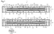
- a polymer electrolyte fuel cell 1 is configured by stacking a plurality of cells 10 together.
- the upper cell 10 in Fig. 1 has a cross-sectional shape taken along such a line that water channels 33, 133, which will be discussed below, are visible.
- the lower cell 10 in Fig. 1 has a cross-sectional shape taken along such a line that gas channels 32, 132, which will be discussed below, are visible.
- Each of the cells 10 has a first frame 11 and a second frame 12, both of which are shaped as a rectangular frame.
- a membrane electrode assembly 15 is arranged in the frames 11, 12. An outer peripheral edge of the membrane electrode assembly 15 is held by the first frame 11 and the second frame 12.
- a supply passage F1 for supplying fuel gas from a non-illustrated fuel gas supply source to the gas channel 32 and a discharge passage F2 for discharging fuel gas that has not been used for power generation to the exterior are formed in the frames 11, 12 and separators 23, 24 of each cell 10.
- a supply passage O1 for supplying oxidant gas from a non-illustrated oxidant gas supply source to the gas channel 32 and a discharge passage 02 for discharging fuel gas that has not been used for power generation to the exterior are formed in the frame 11 and the separator 23 of each cell 10.
- Each of the gas channel forming members 31 is thus arranged between the corresponding membrane electrode assembly 15 and separator 23.
- Each of the gas channel forming members 131 is arranged between the corresponding membrane electrode assembly 15 and separator 24.
- Each of the membrane electrode assemblies 15 has a polymer electrolyte membrane 16.
- Each of the polymer electrolyte membranes 16 is held by a first electrode catalyst layer 17 and a second electrode catalyst layer 18 from the cathode side and the anode side, respectively.
- a first gas diffusion layer 19 is arranged on a surface of each of the first electrode catalyst layers 17.
- a second gas diffusion layer 20 is arranged on a surface of each of the second electrode catalyst layers 18.
- each gas channel forming member 31, 131 will hereafter be described.
- the first gas channel forming member 31 and the second gas channel forming member 131 have the same structure. The description below will thus focus on the configuration of the first gas channel forming member 31.
- Reference numerals "13*”, which are obtained by adding "100" to reference numerals of components of the first gas channel forming member 31, are given to corresponding components of the second gas channel forming member 131 and redundant description is omitted herein.
- the first gas channel forming member 31 and the first separator 23 are referred to in short simply as the gas channel forming member 31 and the separator 23, respectively.
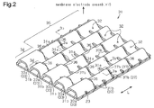
- the gas channel forming member 31 has a substantially corrugated cross section as a whole and is formed by press-molding a single metal plate.
- inner protrusions 31 a which are arranged in parallel, protrude toward the membrane electrode assembly 15 (upward as viewed in Fig. 3A ) and are held in contact with the membrane electrode assembly 15.
- Gas channels 32 through which oxidant gas flows, are each formed between an adjacent pair of the inner protrusions 31a.
- outer protrusions 31 b which are arranged in parallel, protrude toward the separator 23 (downward as viewed in Fig. 3A ) and are held in contact with the first separator 23.
- Water channels 33 for discharging water generated in the membrane electrode assembly 15 (hereinafter, referred to as generated water W) are each formed between an adjacent pair of the outer protrusions 31 b.
- ribs 37 which extend perpendicular to the extending direction L of each of the protrusions 31a, 31 b, are formed in the gas channel forming member 31.
- the ribs 37 are formed by shear-bending each protrusion 31a and corresponding portions of the protrusions 31b that are located adjacent to the protrusion 31 a at opposite sides of the protrusion 31a.
- each of the ribs 37 has an outer section 37a, which is inside the corresponding water channel 33, and an inner section 37b, which is inside the corresponding gas channel 32.
- an outer communication passage 38 which allows an adjacent pair of the water channels 33 to communicate with each other, is formed directly below the inner section 37b of the associated rib 37.
- an inner communication passage 36 which allows the corresponding gas channel 32 and water channel 33 to communicate with each other, is formed directly above the outer section 37a of the associated rib 37.
- the ribs 37 are located closer to the vertices of the outer protrusions 31b than to the vertices of the inner protrusions 31a in the direction of the thickness of the gas channel forming member 31 (in the vertical direction as viewed in Figs. 3A and 3B ).
- the flow cross-sectional area of each outer section 37a is thus greater than the flow cross-sectional area of each inner section 37b as illustrated in Figs. 3A and 3B .
- the pressure loss in the water channels 33 as a whole is greater than that in the gas channels 32 as a whole, even if the gas channels 32 and the water channels 33 have the same flow cross-sectional area at the positions without the ribs 37.
- the oxidant gas flows mainly through the gas channels 32, which cause a comparatively small pressure loss.
- Each inner communication passage 36 is shaped and sized such that the pressure loss in each communication passage 36 exceeds the pressure loss in each gas channel 32.
- the distance between each adjacent pair of the inner communication passages 36 (between each adjacent pair of the outer sections 37a of the ribs 37) is set to a value twice as great as the distance between each adjacent pair of the inner sections 37b of the ribs 37 (each adjacent pair of the outer communication passages 38).
- the inner communication passages 36 (the outer sections 37a) of the ribs 37 are each arranged in every other one of the inner sections 37b (the outer communication passages 38) of the ribs 37.
- each of the outlet sections 34 is formed throughout the section of the associated one of the inner protrusions 31a extending from the most downstream one of the inner communication passages 36 to the outlet opening 33a.
- the flow cross-sectional area of the outlet section 34 of each water channel 33 is thus discretely increased in relation to the flow cross-sectional area of the upstream section 35.
- the outlet opening 33a of each water channel 33 of the gas channel forming member 31 has a chamfered peripheral portion.
- fuel gas is supplied to each gas channel 132 through the corresponding supply passage F1 and then flows into the second gas diffusion layer 20 via the gas channels 132.
- the fuel gas is diffused while passing through the second gas diffusion layer 20 and thus supplied to the second electrode catalyst layer 18.
- Oxidant gas is supplied to each gas channel 32 via the corresponding supply passage O1, diffused while passing through the first gas diffusion layer 19, and supplied to the first electrode catalyst layer 17.
- the fuel gas and the oxidant gas are supplied to the membrane electrode assembly 15, thus causing power generation in the membrane electrode assembly 15 through electrode reaction.
- the generated water W which is generated through the power generation, flows into the gas channels 32 of the first gas channel forming member 31 at the cathode side.
- some of the generated water W flows through the gas channels 32 using flow pressure of the oxidant gas flowing through the gas channels 32. After having flowed through the gas channels 32, the generated water W is discharged to the exterior via the discharge passage 02. As has been described, the pressure loss in each inner communication passage 36 is set greater than the pressure loss in each gas channel 32. This causes the oxidant gas to flow mainly through the gas channels 32, as illustrated in Fig. 6B . Much of the generated water W in the gas channels 32 is thus pushed by the oxidant gas and thus moves in the gas channels 32 toward the discharge passage 02. Some of the generated water W flows into the water channels 33 via the inner communication passages 36. The generated water W in the water channels 33 is pushed by the oxidant gas flowing through the water channels 33 and thus moves in the water channels 33 toward the discharge passage 02.
- Fig. 4B shows the configuration of the end faces of outlet sections of water channels 433 of a first gas channel forming member 431 of a comparative example.
- the flow cross-sectional area of each of the water channels 433 at the end face is constant throughout the water channel 433 in the extending direction of the water channel 433.
- the flow cross-sectional area of an outlet opening 433a of each water channel 433 of the comparative example is equal to the flow cross-sectional area of the upstream section 35 of each water channel 33 of the first embodiment.
- the size of the droplet D of the generated water W at the outlet opening 33a of each water channel 33 becomes greater as the flow cross-sectional area of the outlet opening 33a becomes greater.
- the flow cross-sectional area of the outlet section 34 of each water channel 33 is greater than the flow cross-sectional area of the upstream section 35.
- the size of the droplet D of the generated water W at each outlet opening 33a of the first gas channel forming member 31 of the first embodiment is greater than that of the comparative example, as represented by the long dashed double-short dashed lines in Figs. 4A and 4B .
- the outlet opening 33a of each water channel 33 has the chamfered peripheral portion.
- the size of the droplet D of the generated water W at the outlet opening 33a of each water channel 33 is larger than the corresponding size of the first gas channel forming member 531 ( Fig. 5B ) of the comparative example, in which the outlet opening 533a of each water channel 533 has no chamfered peripheral portion.
- the second gas channel forming member 131 has the same structure as the first gas channel forming member 31. This ensures the same operation of the gas channels 132 and the water channels 133 at the anode side as the aforementioned operation of the gas channels 32 and the water channels 33 at the cathode side.
- the gas channel forming members 31, 131 of the fuel cell 1 and the fuel cell 1 according to the first embodiment, which have been described, have the advantages described below.
- the second embodiment is different from the first embodiment in terms of the configurations of gas channel forming members 231, 331.
- the description below will focus on this difference.
- identical reference numerals are given to components of the second embodiment that are identical with corresponding components of the first embodiment.
- Reference numerals "2**" and “3**”, which are obtained by adding "200" to reference numerals of components of the first embodiment, are given to the components of the second embodiment that correspond to the components of the first embodiment and redundant description is omitted herein.
- the first gas channel forming member 231 and the second gas channel forming member 331 have the same structure.
- the description below will thus focus on the configuration of the first gas channel forming member 231.
- Reference numerals "33*” and “34*”, which are obtained by adding "100" to reference numerals of components of the first gas channel forming member 231, are given to corresponding components of the second gas channel forming member 331 and redundant description is omitted herein.
- the first gas channel forming member 231 and the first separator 23 are referred to in short simply as the gas channel forming member 231 and the separator 23, respectively.
- a first gas channel forming member 231 of each cell 210 is formed by shear-bending a metal plate.
- First projecting portions 236 and second projecting portions 238, each of which projects toward the membrane electrode assembly 15, are formed on a flat base portion 231 a.
- the second projecting portions 238 are spaced apart at predetermined intervals in the flow direction of oxidant gas (hereinafter, referred to as the gas flow direction P), which extends from the non-illustrated supply passage O1 to the discharge passage 02.
- the rows of the second projecting portions 238 are spaced apart at predetermined intervals in the direction perpendicular to the gas flow direction P (hereinafter, referred to as the perpendicular direction Q).
- Each one of the second projecting portions 238 is arranged offset by a half cycle in the gas flow direction P with respect to an adjacent one of the second projecting portions 238 in the perpendicular direction Q.
- the first projecting portions 236 are provided two by two in the clearances between the corresponding adjacent pairs of the second projecting portions 238 in the perpendicular direction Q. Each one of the first projecting portions 236 is arranged offset by a half cycle in the gas flow direction P with respect to an adjacent one of the first projecting portions 236 in the perpendicular direction Q.
- the first projecting portions 236 and the second projecting portions 238 are each held in contact with the membrane electrode assembly 15.
- Gas channels 232, through which oxidant gas flows, are formed between the base portion 231a and the membrane electrode assembly 15.
- the gas channels 232 are configured by main channels h1 each extending in the gas flow direction P and sub-channels h2 each allowing an adjacent pair of the main channels h1 in the perpendicular direction Q to communicate with each other.
- projections 240 are formed in the first gas channel forming member 231 to project toward the first separator 23.
- the projections 240 are formed at the upstream ones of the ends of the corresponding first projecting portions 236 and second projecting portions 238 in the gas flow direction P.
- the projections 240 are held in contact with the first separator 23.
- Water channels 233 are formed between the base portion 231a and the first separator 23.
- the distance between the base portion 231a and the first separator 23 is approximately 20 to 90 ⁇ m.
- a communication hole 237 and a communication hole 239 are formed in the opposite sides of each first projecting portion 236 and the opposite sides of each second projecting portion 238, respectively.
- the communication holes 237, 239 allow the gas channels 232 and the corresponding water channels 233 to communicate with each other.
- the height from the base portion 231a of a projection 240a, which is close to an outlet opening 233a of each water channel 233, is greater than the height from the base portion 231a of a projection 240b, which is spaced from the outlet opening 233a.
- the flow cross-sectional area of each water channel 233 is greater at the location of the projection 240a on the downstream side of the gas flow direction P (at the left side as viewed in Fig. 9 ) than at the location of the projection 240b on the upstream side of the gas flow direction P (at the right side as viewed in the drawing).
- the flow cross-sectional area of an outlet section 234 including the outlet opening 233a is greater than the flow cross-sectional area of an upstream section 235, which is located upstream from the outlet section 234.
- the gas channel forming members 231, 331 of the fuel cell 1 and the fuel cell 1 according to the second embodiment, which have been described, have an advantage similar to the advantage (1) of the first embodiment.
- the gas channel forming members 31, 131 (231, 331) of the fuel cell 1 and the fuel cell 1 according to the present invention are not restricted to the configurations illustrated in the above-described embodiments and may be embodied in forms modified from the configurations as needed, which include, for example, the forms described below.
- the flow cross-sectional area of the outlet section 34 of each water channel 33 is discretely increased in relation to the flow cross-sectional area of the upstream section 35.
- the flow cross-sectional area of the section including the outlet opening of each water channel 33 may be increased gradually toward the outlet opening as illustrated in Fig. 10 , for example.
- the gas channel forming members 31, 131 (231, 331) are arranged at the opposite sides of the membrane electrode assembly 15.
- the gas channel forming member according to the present invention may be arranged at only one of the sides of the membrane electrode assembly 15.
Landscapes
- Life Sciences & Earth Sciences (AREA)
- Engineering & Computer Science (AREA)
- Manufacturing & Machinery (AREA)
- Sustainable Development (AREA)
- Sustainable Energy (AREA)
- Chemical & Material Sciences (AREA)
- Chemical Kinetics & Catalysis (AREA)
- Electrochemistry (AREA)
- General Chemical & Material Sciences (AREA)
- Fuel Cell (AREA)
Abstract
Description
- The present invention relates to a gas channel forming member for a polymer electrolyte fuel cell and to a fuel cell.
- A polymer electrolyte fuel cell includes cells, and each cell is configured by a membrane electrode assembly, a pair of gas channel forming members for holding the membrane electrode assembly in between, and a pair of separators for holding the gas channel forming members in between. The polymer electrolyte fuel cell is configured by stacking the cells together (see, for example, Patent Document 1).
- The membrane electrode assembly is configured by holding a polymer electrolyte membrane between a pair of electrode catalyst layers and is referred to as MEA. A gas diffusion layer is arranged on each of an anode-side surface and a cathode-side surface of the membrane electrode assembly.
- In each of the gas channel forming members, a gas channel, through which fuel gas or oxidant gas flows, is formed between the surface facing the membrane electrode assembly and the membrane electrode assembly. In each gas channel forming member, a water channel for discharging generated water, which is generated through power generation, is formed between the surface facing the corresponding separator and the separator. A communication passage, which allows the gas channel and the water channel to communicate with each other, is formed in the gas channel forming member. The generated water, which is generated in the membrane electrode assembly through power generation, flows into the gas channel. Some of the generated water flows into the water channel through the communication passage and is discharged to the exterior via the water channel using flow pressure of the fuel gas or oxidant gas, which flows through the water channel.
- Patent Document 1: Japanese Laid-Open Patent Publication No.
2011-150801 - In such a fuel cell, the amount of generated water increases when the flow rate of fuel gas or oxidant gas increases, for example, at the time of a high load operation. This may cause the discharge amount of the generated water via the water channel to become smaller than the generation amount of generated water. Some of the generated water is thus retained without being discharged and may flow back into the gas channel via the communication passage, thus blocking the gas channel. This hampers diffusion of the fuel gas or oxidant gas in the membrane electrode assembly through the gas diffusion layer, which decreases cell performance of the fuel cell.
- Accordingly, it is an objective of the present invention to provide a gas channel forming member for a fuel cell and a fuel cell capable of improving discharge performance of generated water and restraining increase of gas pressure loss in a gas channel. Means for Solving the Problems
- To achieve the foregoing objective and in accordance with one aspect of the present invention, a gas channel forming member for a fuel cell is provided. The fuel cell has a separator and a membrane electrode assembly configured by holding a polymer electrolyte membrane between a pair of electrode catalyst layers. The gas channel forming member is arranged between the membrane electrode assembly and the separator. The gas channel forming member includes a plurality of gas channels, which is formed on a surface facing the membrane electrode assembly, a plurality of water channels, which is formed on a surface facing the separator, and a communication passage. Each water channel has an outlet opening. The communication passage allows the gas channels and the water channels to communicate with each other. Fuel gas or oxidant gas flows through the gas channels. The water channels discharge generated water. A flow cross-sectional area of the outlet opening of each water channel is greater than a flow cross-sectional area of an upstream section, which is adjacent to the outlet opening at an upstream side in a flow direction of the gas.
- Droplets of generated water at the outlet opening of the water channel become greater in size as the flow cross-sectional area of the outlet opening becomes larger. In the above-described configuration, the flow cross-sectional area of the outlet opening of the water channel is greater than the flow cross-sectional area of the section upstream from the outlet opening. The size of droplets of generated water at the outlet opening is thus greater than the size of droplets of generated water in the section upstream from the outlet opening. This decreases surface tension of droplets of the generated water, which is adhesion force acting between droplets and the peripheral portion of the outlet opening of the water channel. As a result, the pressure necessary for pushing droplets out of the outlet opening of the water channel is reduced. The generated water is thus discharged to the exterior through the water channel using the gas even if the flow rate or flow pressure of the gas is low.
- If the flow cross-sectional area of the water channel is increased in the extending direction throughout the water channel, the flow cross-sectional area of the gas channel is correspondingly decreased throughout the gas channel in the extending direction of the gas channel. This increases pressure loss of gas in the gas channel compared to the pressure loss in the original gas passage. In the above-described configuration, the upstream section of the water channel, unlike the outlet opening, is formed without an increased flow cross-sectional area. The configuration thus restrains increase in the pressure loss of the gas in the gas channel.
- The present invention thus improves discharge performance of generated water and restrains increase of gas pressure loss in a gas channel.
-
-
Fig. 1 is a cross-sectional view showing afuel cell 1 of a first embodiment; -
Fig. 2 is a cross-sectional perspective view showing a first gas channel forming member and a first separator of the first embodiment; -
Fig. 3A is a cross-sectional view taken alongline 3a-3a ofFig. 2 ; -
Fig. 3B is a cross-sectional view taken alongline 3b-3b ofFig. 2 ; -
Fig. 4A is a diagram showing end faces of outlet sections of water channels of the first gas channel forming member of the first embodiment; -
Fig. 4B is a diagram showing end faces of outlet sections of water channels of a first gas channel forming member of a comparative example; -
Fig. 5A is a cross-sectional view showing the outlet section of the water channel of the first embodiment; -
Fig. 5B is a cross-sectional view showing the outlet section of the water channel of the comparative example; -
Figs. 6A and 6B are schematic diagrams each showing a gas channel and an inner communication passage; -
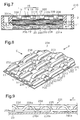
Fig. 7 is a cross-sectional view showing acell 210 of afuel cell 1 of a second embodiment; -
Fig. 8 is a cross-sectional perspective view showing a first gas channel forming member of the second embodiment; -
Fig. 9 is a cross-sectional view mainly showing an outlet section of a water channel of the second embodiment; and -
Fig. 10 is a cross-sectional perspective view showing a first gas channel forming member and a first separator of another embodiment. - Gas
channel forming members fuel cell 1 according to a first embodiment and thefuel cell 1 will now be described with reference toFigs. 1 to 6 . - As shown in
Fig. 1 , a polymerelectrolyte fuel cell 1 is configured by stacking a plurality of cells 10 together. The upper cell 10 inFig. 1 has a cross-sectional shape taken along such a line thatwater channels Fig. 1 has a cross-sectional shape taken along such a line thatgas channels - Each of the cells 10 has a
first frame 11 and asecond frame 12, both of which are shaped as a rectangular frame. Amembrane electrode assembly 15 is arranged in theframes membrane electrode assembly 15 is held by thefirst frame 11 and thesecond frame 12. - A supply passage F1 for supplying fuel gas from a non-illustrated fuel gas supply source to the
gas channel 32 and a discharge passage F2 for discharging fuel gas that has not been used for power generation to the exterior are formed in theframes separators - A supply passage O1 for supplying oxidant gas from a non-illustrated oxidant gas supply source to the
gas channel 32 and adischarge passage 02 for discharging fuel gas that has not been used for power generation to the exterior are formed in theframe 11 and theseparator 23 of each cell 10. - A first gas
channel forming member 31, through which oxidant gas flows, is arranged at a cathode-side surface (at the lower side as viewed inFig. 1 ) of eachmembrane electrode assembly 15. A second gaschannel forming member 131, through which fuel gas (hydrogen gas) flows, is arranged at an anode-side surface (at the upper side as viewed in the drawing) of themembrane electrode assembly 15. - A
first separator 23, which is flat and configured by a metal plate, is arranged at the side of each first gaschannel forming member 31 opposite to the membrane electrode assembly 15 (at the lower side as viewed inFig. 1 ). Asecond separator 24, which is flat and configured by a metal plate, is arranged at the side of each second gaschannel forming member 131 opposite to the membrane electrode assembly 15 (at the upper side as viewed in the drawing). Each of the gaschannel forming members 31 is thus arranged between the correspondingmembrane electrode assembly 15 andseparator 23. Each of the gaschannel forming members 131 is arranged between the correspondingmembrane electrode assembly 15 andseparator 24. - Each of the
membrane electrode assemblies 15 has apolymer electrolyte membrane 16. Each of thepolymer electrolyte membranes 16 is held by a firstelectrode catalyst layer 17 and a secondelectrode catalyst layer 18 from the cathode side and the anode side, respectively. A firstgas diffusion layer 19 is arranged on a surface of each of the first electrode catalyst layers 17. A secondgas diffusion layer 20 is arranged on a surface of each of the second electrode catalyst layers 18. - The structure of each gas
channel forming member channel forming member 31 and the second gaschannel forming member 131 have the same structure. The description below will thus focus on the configuration of the first gaschannel forming member 31. Reference numerals "13*", which are obtained by adding "100" to reference numerals of components of the first gaschannel forming member 31, are given to corresponding components of the second gaschannel forming member 131 and redundant description is omitted herein. The first gaschannel forming member 31 and thefirst separator 23 are referred to in short simply as the gaschannel forming member 31 and theseparator 23, respectively. - As illustrated in
Figs. 2 ,3A, and 3B , the gaschannel forming member 31 has a substantially corrugated cross section as a whole and is formed by press-molding a single metal plate. As a result, in the gaschannel forming member 31,inner protrusions 31 a, which are arranged in parallel, protrude toward the membrane electrode assembly 15 (upward as viewed inFig. 3A ) and are held in contact with themembrane electrode assembly 15.Gas channels 32, through which oxidant gas flows, are each formed between an adjacent pair of theinner protrusions 31a. In the gaschannel forming member 31,outer protrusions 31 b, which are arranged in parallel, protrude toward the separator 23 (downward as viewed inFig. 3A ) and are held in contact with thefirst separator 23.Water channels 33 for discharging water generated in the membrane electrode assembly 15 (hereinafter, referred to as generated water W) are each formed between an adjacent pair of theouter protrusions 31 b. - With reference to
Figs. 2 and3 ,ribs 37, which extend perpendicular to the extending direction L of each of theprotrusions channel forming member 31. Theribs 37 are formed by shear-bending eachprotrusion 31a and corresponding portions of theprotrusions 31b that are located adjacent to theprotrusion 31 a at opposite sides of theprotrusion 31a. - As illustrated in
Figs. 3A and 3B ,communication passages channel forming member 31 by punching thecorresponding ribs 37. That is, each of theribs 37 has anouter section 37a, which is inside the correspondingwater channel 33, and aninner section 37b, which is inside the correspondinggas channel 32. - Referring to
Figs. 1 and3B , in eachouter protrusion 31 b, anouter communication passage 38, which allows an adjacent pair of thewater channels 33 to communicate with each other, is formed directly below theinner section 37b of the associatedrib 37. In eachinner protrusion 31a, aninner communication passage 36, which allows the correspondinggas channel 32 andwater channel 33 to communicate with each other, is formed directly above theouter section 37a of the associatedrib 37. - As illustrated in
Figs. 2 ,3A, and 3B , theribs 37 are located closer to the vertices of theouter protrusions 31b than to the vertices of theinner protrusions 31a in the direction of the thickness of the gas channel forming member 31 (in the vertical direction as viewed inFigs. 3A and 3B ). The flow cross-sectional area of eachouter section 37a is thus greater than the flow cross-sectional area of eachinner section 37b as illustrated inFigs. 3A and 3B . Thus, the pressure loss in thewater channels 33 as a whole is greater than that in thegas channels 32 as a whole, even if thegas channels 32 and thewater channels 33 have the same flow cross-sectional area at the positions without theribs 37. As a result, the oxidant gas flows mainly through thegas channels 32, which cause a comparatively small pressure loss. - Each
inner communication passage 36 is shaped and sized such that the pressure loss in eachcommunication passage 36 exceeds the pressure loss in eachgas channel 32. - With reference to
Fig. 2 , in the aforementioned extending direction L, the distance between each adjacent pair of the inner communication passages 36 (between each adjacent pair of theouter sections 37a of the ribs 37) is set to a value twice as great as the distance between each adjacent pair of theinner sections 37b of the ribs 37 (each adjacent pair of the outer communication passages 38). In the extending direction L and the direction perpendicular to the extending direction L, the inner communication passages 36 (theouter sections 37a) of theribs 37 are each arranged in every other one of theinner sections 37b (the outer communication passages 38) of theribs 37. - With reference to
Figs. 2 ,3, and 4A , in eachwater channel 33 of the gaschannel forming member 31, the flow cross-sectional area of anoutlet section 34 including anoutlet opening 33a, is greater than the flow cross-sectional area of anupstream section 35, which is adjacent to theoutlet section 34 at the upstream side in the flow direction of the oxidant gas. As illustrated inFig. 2 , each of theoutlet sections 34 is formed throughout the section of the associated one of theinner protrusions 31a extending from the most downstream one of theinner communication passages 36 to theoutlet opening 33a. The flow cross-sectional area of theoutlet section 34 of eachwater channel 33 is thus discretely increased in relation to the flow cross-sectional area of theupstream section 35. - Referring to
Fig. 5A , the outlet opening 33a of eachwater channel 33 of the gaschannel forming member 31 has a chamfered peripheral portion. - Operation of the first embodiment will now be described.
- As illustrated at the lower side of
Fig. 1 , fuel gas is supplied to eachgas channel 132 through the corresponding supply passage F1 and then flows into the secondgas diffusion layer 20 via thegas channels 132. The fuel gas is diffused while passing through the secondgas diffusion layer 20 and thus supplied to the secondelectrode catalyst layer 18. - Oxidant gas is supplied to each
gas channel 32 via the corresponding supply passage O1, diffused while passing through the firstgas diffusion layer 19, and supplied to the firstelectrode catalyst layer 17. - In this manner, the fuel gas and the oxidant gas are supplied to the
membrane electrode assembly 15, thus causing power generation in themembrane electrode assembly 15 through electrode reaction. The generated water W, which is generated through the power generation, flows into thegas channels 32 of the first gaschannel forming member 31 at the cathode side. - With reference to
Figs. 6A and 6B , some of the generated water W flows through thegas channels 32 using flow pressure of the oxidant gas flowing through thegas channels 32. After having flowed through thegas channels 32, the generated water W is discharged to the exterior via thedischarge passage 02. As has been described, the pressure loss in eachinner communication passage 36 is set greater than the pressure loss in eachgas channel 32. This causes the oxidant gas to flow mainly through thegas channels 32, as illustrated inFig. 6B . Much of the generated water W in thegas channels 32 is thus pushed by the oxidant gas and thus moves in thegas channels 32 toward thedischarge passage 02. Some of the generated water W flows into thewater channels 33 via theinner communication passages 36. The generated water W in thewater channels 33 is pushed by the oxidant gas flowing through thewater channels 33 and thus moves in thewater channels 33 toward thedischarge passage 02. -
Fig. 4B shows the configuration of the end faces of outlet sections ofwater channels 433 of a first gaschannel forming member 431 of a comparative example. As illustrated in the drawing, the flow cross-sectional area of each of thewater channels 433 at the end face is constant throughout thewater channel 433 in the extending direction of thewater channel 433. The flow cross-sectional area of anoutlet opening 433a of eachwater channel 433 of the comparative example is equal to the flow cross-sectional area of theupstream section 35 of eachwater channel 33 of the first embodiment. - The size of the droplet D of the generated water W at the outlet opening 33a of each
water channel 33 becomes greater as the flow cross-sectional area of theoutlet opening 33a becomes greater. - As illustrated in
Fig. 2 , in the first gaschannel forming member 31 of the first embodiment, the flow cross-sectional area of theoutlet section 34 of eachwater channel 33 is greater than the flow cross-sectional area of theupstream section 35. As a result, the size of the droplet D of the generated water W at each outlet opening 33a of the first gaschannel forming member 31 of the first embodiment is greater than that of the comparative example, as represented by the long dashed double-short dashed lines inFigs. 4A and 4B . - Further, as shown in
Fig. 5A , in the first gaschannel forming member 31 of the first embodiment, the outlet opening 33a of eachwater channel 33 has the chamfered peripheral portion. Thus, the size of the droplet D of the generated water W at the outlet opening 33a of eachwater channel 33, as represented by the long dashed double-short dashed line inFig. 5A , is larger than the corresponding size of the first gas channel forming member 531 (Fig. 5B ) of the comparative example, in which the outlet opening 533a of eachwater channel 533 has no chamfered peripheral portion. - As a result, surface tension of each droplet D of the generated water W, which is adhesion force acting between the droplet D and the peripheral portion of the outlet opening 33a of the
corresponding water channel 33, decreases. This decreases the pressure necessary for pushing the droplet D out of the outlet opening 33a of thewater channel 33. The generated water W is thus discharged to the exterior through thewater channel 33 by means of oxidant gas even if the flow rate or flow pressure of the oxidant gas is comparatively low. - With reference to
Fig. 1 , some of the generated water W, which is generated through power generation, flows into thegas channels 132 of the second gaschannel forming member 131 at the anode side through the secondelectrode catalyst layer 18 and the secondgas diffusion layer 20. In the first embodiment, the second gaschannel forming member 131 has the same structure as the first gaschannel forming member 31. This ensures the same operation of thegas channels 132 and thewater channels 133 at the anode side as the aforementioned operation of thegas channels 32 and thewater channels 33 at the cathode side. - The gas
channel forming members fuel cell 1 and thefuel cell 1 according to the first embodiment, which have been described, have the advantages described below. - (1) Each gas
channel forming member 31 hasgas channels 32,water channels 33, andinner communication passages 36. Thegas channels 32 are arranged in parallel on the surface of the gaschannel forming member 31 facing themembrane electrode assembly 15. Thewater channels 33 are each arranged between an adjacent pair of thegas channels 32 on the surface of the gaschannel forming member 31 facing theseparator 23. Theinner communication passages 36 allow thecorresponding gas channels 32 andwater channels 33 to communicate with each other. Oxidant gas flows through each of thegas channels 32. Each of thewater channels 33 discharges the generated water W. In eachwater channel 33, the flow cross-sectional area of theoutlet section 34 including theoutlet opening 33a is greater than the flow cross-sectional area of theupstream section 35, which is adjacent to theoutlet section 34 at the upstream side in the flow direction of the oxidant gas.
This configuration decreases the pressure necessary for pushing out the droplet D through the outlet opening 33a of eachwater channel 33. The generated water W is thus discharged to the exterior through thewater channels 33 by means of the oxidant gas even if the flow rate or flow pressure of the oxidant gas is comparatively small. Unlike theoutlet sections 34, theupstream section 35 of eachwater channel 33 is formed without an increased flow cross-sectional area. This restrains increase of gas pressure loss in eachgas channel 32. As a result, this configuration improves discharge performance of the generated water W and restrains increase of gas pressure loss in thegas channels 32. This restrains overflow of the generated water W into thegas channels 32, promotes diffusion of the fuel gas and oxidant gas, and improves cell performance. - (2) The
outlet opening 33a of eachwater channel 33 has a chamfered peripheral portion. This configuration enlarges the size of the droplet D of the generated water W at the outlet opening 33a of eachwater channel 33 compared to a configuration without a chamfered peripheral portion formed in theoutlet opening 33a. As a result, adhesion force acting between the droplet D of the generated water W and the peripheral portion of the outlet opening 33a of eachwater channel 33 is further decreased. The generated water W is thus discharged by means of gas even if the flow rate or pressure loss of the gas is comparatively small. - A second embodiment will now be described with reference to
Figs. 7 to 9 . - The second embodiment is different from the first embodiment in terms of the configurations of gas
channel forming members Figs. 7 to 9 , identical reference numerals are given to components of the second embodiment that are identical with corresponding components of the first embodiment. Reference numerals "2**" and "3**", which are obtained by adding "200" to reference numerals of components of the first embodiment, are given to the components of the second embodiment that correspond to the components of the first embodiment and redundant description is omitted herein. - Also in the second embodiment, the first gas
channel forming member 231 and the second gaschannel forming member 331 have the same structure. The description below will thus focus on the configuration of the first gaschannel forming member 231. Reference numerals "33*" and "34*", which are obtained by adding "100" to reference numerals of components of the first gaschannel forming member 231, are given to corresponding components of the second gaschannel forming member 331 and redundant description is omitted herein. The first gaschannel forming member 231 and thefirst separator 23 are referred to in short simply as the gaschannel forming member 231 and theseparator 23, respectively. - As illustrated in
Figs. 7 and 8 , a first gaschannel forming member 231 of eachcell 210 is formed by shear-bending a metal plate. First projectingportions 236 and second projectingportions 238, each of which projects toward themembrane electrode assembly 15, are formed on a flat base portion 231 a. - With reference to
Fig. 8 , the second projectingportions 238 are spaced apart at predetermined intervals in the flow direction of oxidant gas (hereinafter, referred to as the gas flow direction P), which extends from the non-illustrated supply passage O1 to thedischarge passage 02. The rows of the second projectingportions 238 are spaced apart at predetermined intervals in the direction perpendicular to the gas flow direction P (hereinafter, referred to as the perpendicular direction Q). Each one of the second projectingportions 238 is arranged offset by a half cycle in the gas flow direction P with respect to an adjacent one of the second projectingportions 238 in the perpendicular direction Q. - The first projecting
portions 236 are provided two by two in the clearances between the corresponding adjacent pairs of the second projectingportions 238 in the perpendicular direction Q. Each one of the first projectingportions 236 is arranged offset by a half cycle in the gas flow direction P with respect to an adjacent one of the first projectingportions 236 in the perpendicular direction Q. - As illustrated in
Fig. 7 , the first projectingportions 236 and the second projectingportions 238 are each held in contact with themembrane electrode assembly 15.Gas channels 232, through which oxidant gas flows, are formed between the base portion 231a and themembrane electrode assembly 15. - Referring to
Fig. 8 , thegas channels 232 are configured by main channels h1 each extending in the gas flow direction P and sub-channels h2 each allowing an adjacent pair of the main channels h1 in the perpendicular direction Q to communicate with each other. - As shown in
Figs. 7 to 9 ,projections 240 are formed in the first gaschannel forming member 231 to project toward thefirst separator 23. Theprojections 240 are formed at the upstream ones of the ends of the corresponding first projectingportions 236 and second projectingportions 238 in the gas flow direction P. - The
projections 240 are held in contact with thefirst separator 23.Water channels 233 are formed between the base portion 231a and thefirst separator 23. The distance between the base portion 231a and thefirst separator 23 is approximately 20 to 90 µm. - As illustrated in
Fig. 8 , acommunication hole 237 and acommunication hole 239 are formed in the opposite sides of each first projectingportion 236 and the opposite sides of each second projectingportion 238, respectively. The communication holes 237, 239 allow thegas channels 232 and thecorresponding water channels 233 to communicate with each other. - In the second embodiment, referring to
Fig. 9 , the height from the base portion 231a of a projection 240a, which is close to an outlet opening 233a of eachwater channel 233, is greater than the height from the base portion 231a of aprojection 240b, which is spaced from the outlet opening 233a. The flow cross-sectional area of eachwater channel 233 is greater at the location of the projection 240a on the downstream side of the gas flow direction P (at the left side as viewed inFig. 9 ) than at the location of theprojection 240b on the upstream side of the gas flow direction P (at the right side as viewed in the drawing). As a result, in thewater channel 233 as a whole, the flow cross-sectional area of anoutlet section 234 including the outlet opening 233a is greater than the flow cross-sectional area of anupstream section 235, which is located upstream from theoutlet section 234. - The gas
channel forming members fuel cell 1 and thefuel cell 1 according to the second embodiment, which have been described, have an advantage similar to the advantage (1) of the first embodiment. - The gas
channel forming members 31, 131 (231, 331) of thefuel cell 1 and thefuel cell 1 according to the present invention are not restricted to the configurations illustrated in the above-described embodiments and may be embodied in forms modified from the configurations as needed, which include, for example, the forms described below. - In the first embodiment, the flow cross-sectional area of the
outlet section 34 of eachwater channel 33 is discretely increased in relation to the flow cross-sectional area of theupstream section 35. However, the flow cross-sectional area of the section including the outlet opening of eachwater channel 33 may be increased gradually toward the outlet opening as illustrated inFig. 10 , for example. - In the illustrated embodiments, the gas
channel forming members 31, 131 (231, 331) are arranged at the opposite sides of themembrane electrode assembly 15. However, the gas channel forming member according to the present invention may be arranged at only one of the sides of themembrane electrode assembly 15. - 10...cell, 15...membrane electrode assembly, 16...polymer electrolyte membrane, 17...first electrode catalyst layer, 18...second electrode catalyst layer, 19...first gas diffusion layer, 20...second gas diffusion later, 23...first separator, 24...second separator, 31...first gas channel forming member, 31a...inner protrusion, 31b...outer protrusion, 32...gas channel, 33...water channel, 33a...outlet opening, 34...outlet section, 35...upstream section, 36...inner communication passage (communication passage), 37...rib, 37a...outer section, 37b...inner section, 38...outer communication passage, 231...first gas channel forming member, 231a...base portion, 232...gas channel, 233...water channel, 233a...outlet opening, 234...outlet section, 235...upstream section, 236...first projecting portion, 237...communication hole, 238...second projecting portion, 239...communication hole, 240...projection, F1, 01...supply passage, F2, 02...discharge passage.
Claims (6)
- A gas channel forming member for a fuel cell having a separator and a membrane electrode assembly configured by holding a polymer electrolyte membrane between a pair of electrode catalyst layers, wherein the gas channel forming member is arranged between the membrane electrode assembly and the separator, the gas channel forming member comprising:a plurality of gas channels, which is formed on a surface facing the membrane electrode assembly;a plurality of water channels, which is formed on a surface facing the separator and, wherein each water channel has an outlet opening; anda communication passage for allowing the gas channels and the water channels to communicate with each other, whereinfuel gas or oxidant gas flows through the gas channels,the water channels discharge generated water, anda flow cross-sectional area of the outlet opening of each water channel is greater than a flow cross-sectional area of an upstream section, which is adjacent to the outlet opening at an upstream side in a flow direction of the gas.
- The gas channel forming member according to claim 1, wherein
the gas channels are arranged in parallel on the surface facing the membrane electrode assembly, and
the water channels are each arranged between an adjacent pair of the gas channels on the surface facing the separator. - The gas channel forming member according to claim 1 or 2, wherein the flow cross-sectional area of an outlet section including the outlet opening of each of the water channels is discretely increased in relation to the flow cross-sectional area of the upstream section.
- The gas channel forming member according to claim 1 or 2, wherein the flow cross-sectional area of an outlet section including the outlet opening of each of the water channels is increased gradually toward the outlet opening.
- The gas channel forming member according to any one of claims 1 to 4, wherein the outlet opening of each of the water channels has a chamfered peripheral portion.
- A fuel cell comprising:a membrane electrode assembly configured by holding a polymer electrolyte membrane between a pair of electrode catalyst layers;a separator arranged to face the membrane electrode assembly; andthe gas channel forming member according to any one of claims 1 to 5 arranged between the membrane electrode assembly and the separator.
Applications Claiming Priority (2)
| Application Number | Priority Date | Filing Date | Title |
|---|---|---|---|
| JP2013142742A JP6205915B2 (en) | 2013-07-08 | 2013-07-08 | Gas flow path forming member for fuel cell and fuel cell |
| PCT/JP2014/066340 WO2015005094A1 (en) | 2013-07-08 | 2014-06-19 | Gas channel forming member for fuel cells, and fuel cell |
Publications (3)
| Publication Number | Publication Date |
|---|---|
| EP3021394A1 true EP3021394A1 (en) | 2016-05-18 |
| EP3021394A4 EP3021394A4 (en) | 2017-03-15 |
| EP3021394B1 EP3021394B1 (en) | 2018-01-31 |
Family
ID=52279780
Family Applications (1)
| Application Number | Title | Priority Date | Filing Date |
|---|---|---|---|
| EP14822906.5A Active EP3021394B1 (en) | 2013-07-08 | 2014-06-19 | Gas channel forming member for fuel cells, and fuel cell |
Country Status (4)
| Country | Link |
|---|---|
| US (1) | US9960433B2 (en) |
| EP (1) | EP3021394B1 (en) |
| JP (1) | JP6205915B2 (en) |
| WO (1) | WO2015005094A1 (en) |
Cited By (3)
| Publication number | Priority date | Publication date | Assignee | Title |
|---|---|---|---|---|
| CN109616682A (en) * | 2017-10-04 | 2019-04-12 | 丰田车体株式会社 | Fuel cell forms plate and fuel cell unit with gas flow |
| CN109616683A (en) * | 2017-10-04 | 2019-04-12 | 丰田车体株式会社 | Fuel cell forms plate and fuel cell unit with gas flow |
| EP4002523A4 (en) * | 2019-07-19 | 2023-08-16 | Toyota Shatai Kabushiki Kaisha | Fuel cell stack |
Families Citing this family (8)
| Publication number | Priority date | Publication date | Assignee | Title |
|---|---|---|---|---|
| KR101959469B1 (en) * | 2015-07-31 | 2019-07-02 | 주식회사 엘지화학 | Separator, and Fuel cell stack comprising the same |
| JP6406170B2 (en) * | 2015-08-21 | 2018-10-17 | トヨタ車体株式会社 | Gas flow path forming plate for fuel cell and fuel cell stack |
| JP6458286B2 (en) | 2015-08-21 | 2019-01-30 | トヨタ車体株式会社 | Gas flow path forming plate for fuel cell and fuel cell stack |
| JP6454904B2 (en) * | 2015-08-21 | 2019-01-23 | トヨタ車体株式会社 | Gas flow path forming plate for fuel cell and fuel cell stack |
| JP6696279B2 (en) * | 2016-04-12 | 2020-05-20 | トヨタ自動車株式会社 | Fuel cell |
| JP6551291B2 (en) * | 2016-04-19 | 2019-07-31 | トヨタ車体株式会社 | Fuel cell gas flow path forming plate and fuel cell stack |
| EP3240079B1 (en) | 2016-04-27 | 2018-12-19 | Toyota Shatai Kabushiki Kaisha | Gas channel forming plate for fuel cell and fuel cell stack |
| JP6874403B2 (en) * | 2017-02-03 | 2021-05-19 | トヨタ自動車株式会社 | Fuel cell |
Family Cites Families (17)
| Publication number | Priority date | Publication date | Assignee | Title |
|---|---|---|---|---|
| JPH1173979A (en) | 1997-08-28 | 1999-03-16 | Fuji Electric Co Ltd | Solid polymer electrolyte fuel cell |
| JP2001185169A (en) | 1999-12-24 | 2001-07-06 | Sanyo Electric Co Ltd | Solid polymeric fuel cell |
| JP4993828B2 (en) * | 2001-09-06 | 2012-08-08 | 株式会社日本自動車部品総合研究所 | Fuel cell |
| JP4345265B2 (en) * | 2002-07-05 | 2009-10-14 | トヨタ自動車株式会社 | Fuel cell |
| JP4321038B2 (en) | 2002-10-25 | 2009-08-26 | アイシン精機株式会社 | Polymer electrolyte fuel cell |
| JP2007250259A (en) | 2006-03-14 | 2007-09-27 | Toyota Motor Corp | Fuel cell |
| EP1978585A4 (en) | 2006-01-19 | 2011-10-26 | Toyota Motor Co Ltd | Fuel cell |
| JP5021219B2 (en) | 2006-03-01 | 2012-09-05 | 本田技研工業株式会社 | Fuel cell stack |
| TW200737576A (en) * | 2006-03-24 | 2007-10-01 | Asia Pacific Fuel Cell Tech | Gas-inlet pressure adjustment structure for bipolar plate of fuel cell stack |
| JP2008171638A (en) * | 2007-01-10 | 2008-07-24 | Toyota Motor Corp | Fuel cell separator |
| JP5245315B2 (en) * | 2007-07-31 | 2013-07-24 | 日産自動車株式会社 | Fuel cell |
| JP5123824B2 (en) * | 2008-11-06 | 2013-01-23 | 本田技研工業株式会社 | FUEL CELL STACK AND METHOD OF OPERATING FUEL CELL STACK |
| JP5560728B2 (en) * | 2010-01-19 | 2014-07-30 | トヨタ車体株式会社 | Fuel cell |
| JP5648293B2 (en) * | 2010-02-12 | 2015-01-07 | トヨタ車体株式会社 | Fuel cell |
| JP5678276B2 (en) | 2011-04-18 | 2015-02-25 | トヨタ車体株式会社 | Fuel cell |
| CA2763787C (en) | 2011-05-26 | 2013-11-12 | Toyota Jidosha Kabushiki Kaisha | Separator for fuel cell and fuel cell |
| JP6036825B2 (en) * | 2012-07-17 | 2016-12-07 | トヨタ車体株式会社 | Fuel cell |
-
2013
- 2013-07-08 JP JP2013142742A patent/JP6205915B2/en active Active
-
2014
- 2014-06-19 WO PCT/JP2014/066340 patent/WO2015005094A1/en active Application Filing
- 2014-06-19 EP EP14822906.5A patent/EP3021394B1/en active Active
- 2014-06-19 US US14/780,046 patent/US9960433B2/en active Active
Cited By (4)
| Publication number | Priority date | Publication date | Assignee | Title |
|---|---|---|---|---|
| CN109616682A (en) * | 2017-10-04 | 2019-04-12 | 丰田车体株式会社 | Fuel cell forms plate and fuel cell unit with gas flow |
| CN109616683A (en) * | 2017-10-04 | 2019-04-12 | 丰田车体株式会社 | Fuel cell forms plate and fuel cell unit with gas flow |
| CN109616683B (en) * | 2017-10-04 | 2022-06-10 | 丰田车体株式会社 | Gas flow channel forming plate for fuel cell and fuel cell stack |
| EP4002523A4 (en) * | 2019-07-19 | 2023-08-16 | Toyota Shatai Kabushiki Kaisha | Fuel cell stack |
Also Published As
| Publication number | Publication date |
|---|---|
| US9960433B2 (en) | 2018-05-01 |
| US20160043412A1 (en) | 2016-02-11 |
| EP3021394B1 (en) | 2018-01-31 |
| EP3021394A4 (en) | 2017-03-15 |
| WO2015005094A1 (en) | 2015-01-15 |
| JP2015015218A (en) | 2015-01-22 |
| JP6205915B2 (en) | 2017-10-04 |
Similar Documents
| Publication | Publication Date | Title |
|---|---|---|
| EP3021394B1 (en) | Gas channel forming member for fuel cells, and fuel cell | |
| EP2876715B1 (en) | Fuel cell | |
| CN107810573B (en) | Separator, method of manufacturing the same, and fuel cell stack including the same | |
| US9088015B2 (en) | Fuel cell comprising water discharge channel formed by a corrugated section | |
| US8911917B2 (en) | Fuel cell | |
| US9214682B2 (en) | Fuel cell | |
| KR101664035B1 (en) | Separator and fuel cell with the same | |
| CN103250290A (en) | Fuel cell and fuel cell stack | |
| EP3133685B1 (en) | Gas channel forming plate for fuel cell and fuel cell stack | |
| EP2963710A1 (en) | Gas flow path forming bodies of fuel cell, and fuel cell | |
| WO2013105956A1 (en) | Fuel cell reactant flow field having impediments to flow | |
| JP6454904B2 (en) | Gas flow path forming plate for fuel cell and fuel cell stack | |
| CN106207235A (en) | There is the fuel cell of the reactant distribution of improvement | |
| US9147891B2 (en) | Fuel cell stack | |
| JP6406170B2 (en) | Gas flow path forming plate for fuel cell and fuel cell stack | |
| EP2654113A1 (en) | Fuel cell | |
| KR20190130306A (en) | Separator for feul cell | |
| JP5993622B2 (en) | Fuel cell | |
| US20150214558A1 (en) | Fuel cell component having dimensions selected to maximize a useful area | |
| JP6403099B2 (en) | Fuel cell module | |
| EP4084160A1 (en) | Separator for fuel battery | |
| KR101141495B1 (en) | Fuel cell stack having convex coolant guideline | |
| KR20240097018A (en) | Separator for feul cell | |
| KR20240047113A (en) | Separator for feul cell | |
| KR20240028148A (en) | Separator for feul cell |
Legal Events
| Date | Code | Title | Description |
|---|---|---|---|
| PUAI | Public reference made under article 153(3) epc to a published international application that has entered the european phase |
Free format text: ORIGINAL CODE: 0009012 |
|
| 17P | Request for examination filed |
Effective date: 20150923 |
|
| AK | Designated contracting states |
Kind code of ref document: A1 Designated state(s): AL AT BE BG CH CY CZ DE DK EE ES FI FR GB GR HR HU IE IS IT LI LT LU LV MC MK MT NL NO PL PT RO RS SE SI SK SM TR |
|
| AX | Request for extension of the european patent |
Extension state: BA ME |
|
| DAX | Request for extension of the european patent (deleted) | ||
| A4 | Supplementary search report drawn up and despatched |
Effective date: 20170210 |
|
| RIC1 | Information provided on ipc code assigned before grant |
Ipc: H01M 8/04119 20160101ALI20170203BHEP Ipc: H01M 8/0258 20160101AFI20170203BHEP Ipc: H01M 8/1018 20160101ALN20170203BHEP |
|
| REG | Reference to a national code |
Ref country code: DE Ref legal event code: R079 Ref document number: 602014020598 Country of ref document: DE Free format text: PREVIOUS MAIN CLASS: H01M0008020000 Ipc: H01M0008025800 |
|
| GRAP | Despatch of communication of intention to grant a patent |
Free format text: ORIGINAL CODE: EPIDOSNIGR1 |
|
| RIC1 | Information provided on ipc code assigned before grant |
Ipc: H01M 8/1018 20160101ALN20171011BHEP Ipc: H01M 8/0258 20160101AFI20171011BHEP Ipc: H01M 8/04119 20160101ALI20171011BHEP |
|
| RIC1 | Information provided on ipc code assigned before grant |
Ipc: H01M 8/1018 20160101ALN20171018BHEP Ipc: H01M 8/0258 20160101AFI20171018BHEP Ipc: H01M 8/04119 20160101ALI20171018BHEP |
|
| INTG | Intention to grant announced |
Effective date: 20171031 |
|
| GRAS | Grant fee paid |
Free format text: ORIGINAL CODE: EPIDOSNIGR3 |
|
| GRAA | (expected) grant |
Free format text: ORIGINAL CODE: 0009210 |
|
| AK | Designated contracting states |
Kind code of ref document: B1 Designated state(s): AL AT BE BG CH CY CZ DE DK EE ES FI FR GB GR HR HU IE IS IT LI LT LU LV MC MK MT NL NO PL PT RO RS SE SI SK SM TR |
|
| REG | Reference to a national code |
Ref country code: GB Ref legal event code: FG4D Ref country code: CH Ref legal event code: EP |
|
| REG | Reference to a national code |
Ref country code: AT Ref legal event code: REF Ref document number: 968127 Country of ref document: AT Kind code of ref document: T Effective date: 20180215 |
|
| REG | Reference to a national code |
Ref country code: IE Ref legal event code: FG4D |
|
| REG | Reference to a national code |
Ref country code: DE Ref legal event code: R096 Ref document number: 602014020598 Country of ref document: DE |
|
| REG | Reference to a national code |
Ref country code: NL Ref legal event code: MP Effective date: 20180131 |
|
| REG | Reference to a national code |
Ref country code: LT Ref legal event code: MG4D |
|
| REG | Reference to a national code |
Ref country code: AT Ref legal event code: MK05 Ref document number: 968127 Country of ref document: AT Kind code of ref document: T Effective date: 20180131 |
|
| REG | Reference to a national code |
Ref country code: FR Ref legal event code: PLFP Year of fee payment: 5 |
|
| PG25 | Lapsed in a contracting state [announced via postgrant information from national office to epo] |
Ref country code: NO Free format text: LAPSE BECAUSE OF FAILURE TO SUBMIT A TRANSLATION OF THE DESCRIPTION OR TO PAY THE FEE WITHIN THE PRESCRIBED TIME-LIMIT Effective date: 20180430 Ref country code: ES Free format text: LAPSE BECAUSE OF FAILURE TO SUBMIT A TRANSLATION OF THE DESCRIPTION OR TO PAY THE FEE WITHIN THE PRESCRIBED TIME-LIMIT Effective date: 20180131 Ref country code: HR Free format text: LAPSE BECAUSE OF FAILURE TO SUBMIT A TRANSLATION OF THE DESCRIPTION OR TO PAY THE FEE WITHIN THE PRESCRIBED TIME-LIMIT Effective date: 20180131 Ref country code: FI Free format text: LAPSE BECAUSE OF FAILURE TO SUBMIT A TRANSLATION OF THE DESCRIPTION OR TO PAY THE FEE WITHIN THE PRESCRIBED TIME-LIMIT Effective date: 20180131 Ref country code: LT Free format text: LAPSE BECAUSE OF FAILURE TO SUBMIT A TRANSLATION OF THE DESCRIPTION OR TO PAY THE FEE WITHIN THE PRESCRIBED TIME-LIMIT Effective date: 20180131 Ref country code: NL Free format text: LAPSE BECAUSE OF FAILURE TO SUBMIT A TRANSLATION OF THE DESCRIPTION OR TO PAY THE FEE WITHIN THE PRESCRIBED TIME-LIMIT Effective date: 20180131 |
|
| PG25 | Lapsed in a contracting state [announced via postgrant information from national office to epo] |
Ref country code: SE Free format text: LAPSE BECAUSE OF FAILURE TO SUBMIT A TRANSLATION OF THE DESCRIPTION OR TO PAY THE FEE WITHIN THE PRESCRIBED TIME-LIMIT Effective date: 20180131 Ref country code: BG Free format text: LAPSE BECAUSE OF FAILURE TO SUBMIT A TRANSLATION OF THE DESCRIPTION OR TO PAY THE FEE WITHIN THE PRESCRIBED TIME-LIMIT Effective date: 20180430 Ref country code: IS Free format text: LAPSE BECAUSE OF FAILURE TO SUBMIT A TRANSLATION OF THE DESCRIPTION OR TO PAY THE FEE WITHIN THE PRESCRIBED TIME-LIMIT Effective date: 20180531 Ref country code: LV Free format text: LAPSE BECAUSE OF FAILURE TO SUBMIT A TRANSLATION OF THE DESCRIPTION OR TO PAY THE FEE WITHIN THE PRESCRIBED TIME-LIMIT Effective date: 20180131 Ref country code: RS Free format text: LAPSE BECAUSE OF FAILURE TO SUBMIT A TRANSLATION OF THE DESCRIPTION OR TO PAY THE FEE WITHIN THE PRESCRIBED TIME-LIMIT Effective date: 20180131 Ref country code: PL Free format text: LAPSE BECAUSE OF FAILURE TO SUBMIT A TRANSLATION OF THE DESCRIPTION OR TO PAY THE FEE WITHIN THE PRESCRIBED TIME-LIMIT Effective date: 20180131 Ref country code: AT Free format text: LAPSE BECAUSE OF FAILURE TO SUBMIT A TRANSLATION OF THE DESCRIPTION OR TO PAY THE FEE WITHIN THE PRESCRIBED TIME-LIMIT Effective date: 20180131 Ref country code: GR Free format text: LAPSE BECAUSE OF FAILURE TO SUBMIT A TRANSLATION OF THE DESCRIPTION OR TO PAY THE FEE WITHIN THE PRESCRIBED TIME-LIMIT Effective date: 20180501 |
|
| PG25 | Lapsed in a contracting state [announced via postgrant information from national office to epo] |
Ref country code: RO Free format text: LAPSE BECAUSE OF FAILURE TO SUBMIT A TRANSLATION OF THE DESCRIPTION OR TO PAY THE FEE WITHIN THE PRESCRIBED TIME-LIMIT Effective date: 20180131 Ref country code: IT Free format text: LAPSE BECAUSE OF FAILURE TO SUBMIT A TRANSLATION OF THE DESCRIPTION OR TO PAY THE FEE WITHIN THE PRESCRIBED TIME-LIMIT Effective date: 20180131 Ref country code: EE Free format text: LAPSE BECAUSE OF FAILURE TO SUBMIT A TRANSLATION OF THE DESCRIPTION OR TO PAY THE FEE WITHIN THE PRESCRIBED TIME-LIMIT Effective date: 20180131 Ref country code: AL Free format text: LAPSE BECAUSE OF FAILURE TO SUBMIT A TRANSLATION OF THE DESCRIPTION OR TO PAY THE FEE WITHIN THE PRESCRIBED TIME-LIMIT Effective date: 20180131 |
|
| REG | Reference to a national code |
Ref country code: DE Ref legal event code: R097 Ref document number: 602014020598 Country of ref document: DE |
|
| PG25 | Lapsed in a contracting state [announced via postgrant information from national office to epo] |
Ref country code: CZ Free format text: LAPSE BECAUSE OF FAILURE TO SUBMIT A TRANSLATION OF THE DESCRIPTION OR TO PAY THE FEE WITHIN THE PRESCRIBED TIME-LIMIT Effective date: 20180131 Ref country code: SK Free format text: LAPSE BECAUSE OF FAILURE TO SUBMIT A TRANSLATION OF THE DESCRIPTION OR TO PAY THE FEE WITHIN THE PRESCRIBED TIME-LIMIT Effective date: 20180131 Ref country code: SM Free format text: LAPSE BECAUSE OF FAILURE TO SUBMIT A TRANSLATION OF THE DESCRIPTION OR TO PAY THE FEE WITHIN THE PRESCRIBED TIME-LIMIT Effective date: 20180131 Ref country code: DK Free format text: LAPSE BECAUSE OF FAILURE TO SUBMIT A TRANSLATION OF THE DESCRIPTION OR TO PAY THE FEE WITHIN THE PRESCRIBED TIME-LIMIT Effective date: 20180131 |
|
| PLBE | No opposition filed within time limit |
Free format text: ORIGINAL CODE: 0009261 |
|
| STAA | Information on the status of an ep patent application or granted ep patent |
Free format text: STATUS: NO OPPOSITION FILED WITHIN TIME LIMIT |
|
| 26N | No opposition filed |
Effective date: 20181102 |
|
| REG | Reference to a national code |
Ref country code: CH Ref legal event code: PL |
|
| PG25 | Lapsed in a contracting state [announced via postgrant information from national office to epo] |
Ref country code: SI Free format text: LAPSE BECAUSE OF FAILURE TO SUBMIT A TRANSLATION OF THE DESCRIPTION OR TO PAY THE FEE WITHIN THE PRESCRIBED TIME-LIMIT Effective date: 20180131 |
|
| REG | Reference to a national code |
Ref country code: BE Ref legal event code: MM Effective date: 20180630 |
|
| REG | Reference to a national code |
Ref country code: IE Ref legal event code: MM4A |
|
| PG25 | Lapsed in a contracting state [announced via postgrant information from national office to epo] |
Ref country code: MC Free format text: LAPSE BECAUSE OF FAILURE TO SUBMIT A TRANSLATION OF THE DESCRIPTION OR TO PAY THE FEE WITHIN THE PRESCRIBED TIME-LIMIT Effective date: 20180131 Ref country code: LU Free format text: LAPSE BECAUSE OF NON-PAYMENT OF DUE FEES Effective date: 20180619 |
|
| PG25 | Lapsed in a contracting state [announced via postgrant information from national office to epo] |
Ref country code: LI Free format text: LAPSE BECAUSE OF NON-PAYMENT OF DUE FEES Effective date: 20180630 Ref country code: IE Free format text: LAPSE BECAUSE OF NON-PAYMENT OF DUE FEES Effective date: 20180619 Ref country code: CH Free format text: LAPSE BECAUSE OF NON-PAYMENT OF DUE FEES Effective date: 20180630 |
|
| PG25 | Lapsed in a contracting state [announced via postgrant information from national office to epo] |
Ref country code: BE Free format text: LAPSE BECAUSE OF NON-PAYMENT OF DUE FEES Effective date: 20180630 |
|
| PG25 | Lapsed in a contracting state [announced via postgrant information from national office to epo] |
Ref country code: MT Free format text: LAPSE BECAUSE OF NON-PAYMENT OF DUE FEES Effective date: 20180619 |
|
| PG25 | Lapsed in a contracting state [announced via postgrant information from national office to epo] |
Ref country code: TR Free format text: LAPSE BECAUSE OF FAILURE TO SUBMIT A TRANSLATION OF THE DESCRIPTION OR TO PAY THE FEE WITHIN THE PRESCRIBED TIME-LIMIT Effective date: 20180131 |
|
| PG25 | Lapsed in a contracting state [announced via postgrant information from national office to epo] |
Ref country code: PT Free format text: LAPSE BECAUSE OF FAILURE TO SUBMIT A TRANSLATION OF THE DESCRIPTION OR TO PAY THE FEE WITHIN THE PRESCRIBED TIME-LIMIT Effective date: 20180131 |
|
| PG25 | Lapsed in a contracting state [announced via postgrant information from national office to epo] |
Ref country code: HU Free format text: LAPSE BECAUSE OF FAILURE TO SUBMIT A TRANSLATION OF THE DESCRIPTION OR TO PAY THE FEE WITHIN THE PRESCRIBED TIME-LIMIT; INVALID AB INITIO Effective date: 20140619 Ref country code: CY Free format text: LAPSE BECAUSE OF FAILURE TO SUBMIT A TRANSLATION OF THE DESCRIPTION OR TO PAY THE FEE WITHIN THE PRESCRIBED TIME-LIMIT Effective date: 20180131 Ref country code: MK Free format text: LAPSE BECAUSE OF NON-PAYMENT OF DUE FEES Effective date: 20180131 |
|
| PGFP | Annual fee paid to national office [announced via postgrant information from national office to epo] |
Ref country code: DE Payment date: 20230502 Year of fee payment: 10 |
|
| PGFP | Annual fee paid to national office [announced via postgrant information from national office to epo] |
Ref country code: GB Payment date: 20240502 Year of fee payment: 11 |
|
| PGFP | Annual fee paid to national office [announced via postgrant information from national office to epo] |
Ref country code: FR Payment date: 20240509 Year of fee payment: 11 |