EP3021379A1 - Lithium ion battery and lithium ion battery pack - Google Patents
Lithium ion battery and lithium ion battery pack Download PDFInfo
- Publication number
- EP3021379A1 EP3021379A1 EP15177802.4A EP15177802A EP3021379A1 EP 3021379 A1 EP3021379 A1 EP 3021379A1 EP 15177802 A EP15177802 A EP 15177802A EP 3021379 A1 EP3021379 A1 EP 3021379A1
- Authority
- EP
- European Patent Office
- Prior art keywords
- lithium ion
- battery
- air flow
- flow channel
- ion battery
- Prior art date
- Legal status (The legal status is an assumption and is not a legal conclusion. Google has not performed a legal analysis and makes no representation as to the accuracy of the status listed.)
- Granted
Links
- HBBGRARXTFLTSG-UHFFFAOYSA-N Lithium ion Chemical compound [Li+] HBBGRARXTFLTSG-UHFFFAOYSA-N 0.000 title claims abstract description 92
- 229910001416 lithium ion Inorganic materials 0.000 title claims abstract description 92
- 229910052751 metal Inorganic materials 0.000 claims description 7
- 239000002184 metal Substances 0.000 claims description 7
- -1 polyethylene terephthalate Polymers 0.000 claims description 6
- 239000004743 Polypropylene Substances 0.000 claims description 5
- 239000000919 ceramic Substances 0.000 claims description 5
- 239000005020 polyethylene terephthalate Substances 0.000 claims description 4
- 229920000139 polyethylene terephthalate Polymers 0.000 claims description 4
- KXGFMDJXCMQABM-UHFFFAOYSA-N 2-methoxy-6-methylphenol Chemical compound [CH]OC1=CC=CC([CH])=C1O KXGFMDJXCMQABM-UHFFFAOYSA-N 0.000 claims description 3
- 239000004809 Teflon Substances 0.000 claims description 3
- 229920006362 Teflon® Polymers 0.000 claims description 3
- 229920001568 phenolic resin Polymers 0.000 claims description 3
- 239000005011 phenolic resin Substances 0.000 claims description 3
- 229920001155 polypropylene Polymers 0.000 claims description 3
- 239000003822 epoxy resin Substances 0.000 claims description 2
- 229920000647 polyepoxide Polymers 0.000 claims description 2
- 239000007789 gas Substances 0.000 description 47
- 239000007787 solid Substances 0.000 description 28
- 239000002245 particle Substances 0.000 description 26
- 239000003792 electrolyte Substances 0.000 description 7
- 238000004880 explosion Methods 0.000 description 6
- 230000000903 blocking effect Effects 0.000 description 5
- PXHVJJICTQNCMI-UHFFFAOYSA-N Nickel Chemical compound [Ni] PXHVJJICTQNCMI-UHFFFAOYSA-N 0.000 description 4
- 239000000463 material Substances 0.000 description 4
- 230000009172 bursting Effects 0.000 description 3
- 230000007797 corrosion Effects 0.000 description 3
- 238000005260 corrosion Methods 0.000 description 3
- 238000007599 discharging Methods 0.000 description 3
- 239000000203 mixture Substances 0.000 description 3
- 238000005476 soldering Methods 0.000 description 3
- 229910000838 Al alloy Inorganic materials 0.000 description 2
- 229910000990 Ni alloy Inorganic materials 0.000 description 2
- 238000009825 accumulation Methods 0.000 description 2
- 239000011149 active material Substances 0.000 description 2
- 229910052782 aluminium Inorganic materials 0.000 description 2
- XAGFODPZIPBFFR-UHFFFAOYSA-N aluminium Chemical compound [Al] XAGFODPZIPBFFR-UHFFFAOYSA-N 0.000 description 2
- 230000008901 benefit Effects 0.000 description 2
- 230000000694 effects Effects 0.000 description 2
- 239000007769 metal material Substances 0.000 description 2
- 238000012986 modification Methods 0.000 description 2
- 230000004048 modification Effects 0.000 description 2
- 229910052759 nickel Inorganic materials 0.000 description 2
- 239000004033 plastic Substances 0.000 description 2
- 229920003023 plastic Polymers 0.000 description 2
- 238000011076 safety test Methods 0.000 description 2
- 239000010935 stainless steel Substances 0.000 description 2
- 229910001220 stainless steel Inorganic materials 0.000 description 2
- 239000004593 Epoxy Substances 0.000 description 1
- WHXSMMKQMYFTQS-UHFFFAOYSA-N Lithium Chemical compound [Li] WHXSMMKQMYFTQS-UHFFFAOYSA-N 0.000 description 1
- 239000004698 Polyethylene Substances 0.000 description 1
- 230000015572 biosynthetic process Effects 0.000 description 1
- 229910010293 ceramic material Inorganic materials 0.000 description 1
- 238000006243 chemical reaction Methods 0.000 description 1
- 229910003460 diamond Inorganic materials 0.000 description 1
- 239000010432 diamond Substances 0.000 description 1
- 238000004146 energy storage Methods 0.000 description 1
- 230000002708 enhancing effect Effects 0.000 description 1
- 238000001914 filtration Methods 0.000 description 1
- 238000009413 insulation Methods 0.000 description 1
- 229910052744 lithium Inorganic materials 0.000 description 1
- 239000000155 melt Substances 0.000 description 1
- 150000002739 metals Chemical class 0.000 description 1
- 238000000465 moulding Methods 0.000 description 1
- 238000006479 redox reaction Methods 0.000 description 1
Images


Classifications
-
- H—ELECTRICITY
- H01—ELECTRIC ELEMENTS
- H01M—PROCESSES OR MEANS, e.g. BATTERIES, FOR THE DIRECT CONVERSION OF CHEMICAL ENERGY INTO ELECTRICAL ENERGY
- H01M10/00—Secondary cells; Manufacture thereof
- H01M10/05—Accumulators with non-aqueous electrolyte
- H01M10/052—Li-accumulators
-
- H—ELECTRICITY
- H01—ELECTRIC ELEMENTS
- H01M—PROCESSES OR MEANS, e.g. BATTERIES, FOR THE DIRECT CONVERSION OF CHEMICAL ENERGY INTO ELECTRICAL ENERGY
- H01M10/00—Secondary cells; Manufacture thereof
- H01M10/05—Accumulators with non-aqueous electrolyte
- H01M10/052—Li-accumulators
- H01M10/0525—Rocking-chair batteries, i.e. batteries with lithium insertion or intercalation in both electrodes; Lithium-ion batteries
-
- H—ELECTRICITY
- H01—ELECTRIC ELEMENTS
- H01M—PROCESSES OR MEANS, e.g. BATTERIES, FOR THE DIRECT CONVERSION OF CHEMICAL ENERGY INTO ELECTRICAL ENERGY
- H01M50/00—Constructional details or processes of manufacture of the non-active parts of electrochemical cells other than fuel cells, e.g. hybrid cells
- H01M50/10—Primary casings, jackets or wrappings of a single cell or a single battery
- H01M50/102—Primary casings, jackets or wrappings of a single cell or a single battery characterised by their shape or physical structure
- H01M50/103—Primary casings, jackets or wrappings of a single cell or a single battery characterised by their shape or physical structure prismatic or rectangular
-
- H—ELECTRICITY
- H01—ELECTRIC ELEMENTS
- H01M—PROCESSES OR MEANS, e.g. BATTERIES, FOR THE DIRECT CONVERSION OF CHEMICAL ENERGY INTO ELECTRICAL ENERGY
- H01M50/00—Constructional details or processes of manufacture of the non-active parts of electrochemical cells other than fuel cells, e.g. hybrid cells
- H01M50/30—Arrangements for facilitating escape of gases
- H01M50/342—Non-re-sealable arrangements
- H01M50/3425—Non-re-sealable arrangements in the form of rupturable membranes or weakened parts, e.g. pierced with the aid of a sharp member
-
- H—ELECTRICITY
- H01—ELECTRIC ELEMENTS
- H01M—PROCESSES OR MEANS, e.g. BATTERIES, FOR THE DIRECT CONVERSION OF CHEMICAL ENERGY INTO ELECTRICAL ENERGY
- H01M50/00—Constructional details or processes of manufacture of the non-active parts of electrochemical cells other than fuel cells, e.g. hybrid cells
- H01M50/30—Arrangements for facilitating escape of gases
- H01M50/383—Flame arresting or ignition-preventing means
-
- H—ELECTRICITY
- H01—ELECTRIC ELEMENTS
- H01M—PROCESSES OR MEANS, e.g. BATTERIES, FOR THE DIRECT CONVERSION OF CHEMICAL ENERGY INTO ELECTRICAL ENERGY
- H01M50/00—Constructional details or processes of manufacture of the non-active parts of electrochemical cells other than fuel cells, e.g. hybrid cells
- H01M50/30—Arrangements for facilitating escape of gases
- H01M50/394—Gas-pervious parts or elements
-
- H—ELECTRICITY
- H01—ELECTRIC ELEMENTS
- H01M—PROCESSES OR MEANS, e.g. BATTERIES, FOR THE DIRECT CONVERSION OF CHEMICAL ENERGY INTO ELECTRICAL ENERGY
- H01M2200/00—Safety devices for primary or secondary batteries
- H01M2200/20—Pressure-sensitive devices
-
- H—ELECTRICITY
- H01—ELECTRIC ELEMENTS
- H01M—PROCESSES OR MEANS, e.g. BATTERIES, FOR THE DIRECT CONVERSION OF CHEMICAL ENERGY INTO ELECTRICAL ENERGY
- H01M2220/00—Batteries for particular applications
- H01M2220/10—Batteries in stationary systems, e.g. emergency power source in plant
-
- H—ELECTRICITY
- H01—ELECTRIC ELEMENTS
- H01M—PROCESSES OR MEANS, e.g. BATTERIES, FOR THE DIRECT CONVERSION OF CHEMICAL ENERGY INTO ELECTRICAL ENERGY
- H01M2220/00—Batteries for particular applications
- H01M2220/20—Batteries in motive systems, e.g. vehicle, ship, plane
-
- Y—GENERAL TAGGING OF NEW TECHNOLOGICAL DEVELOPMENTS; GENERAL TAGGING OF CROSS-SECTIONAL TECHNOLOGIES SPANNING OVER SEVERAL SECTIONS OF THE IPC; TECHNICAL SUBJECTS COVERED BY FORMER USPC CROSS-REFERENCE ART COLLECTIONS [XRACs] AND DIGESTS
- Y02—TECHNOLOGIES OR APPLICATIONS FOR MITIGATION OR ADAPTATION AGAINST CLIMATE CHANGE
- Y02E—REDUCTION OF GREENHOUSE GAS [GHG] EMISSIONS, RELATED TO ENERGY GENERATION, TRANSMISSION OR DISTRIBUTION
- Y02E60/00—Enabling technologies; Technologies with a potential or indirect contribution to GHG emissions mitigation
- Y02E60/10—Energy storage using batteries
-
- Y—GENERAL TAGGING OF NEW TECHNOLOGICAL DEVELOPMENTS; GENERAL TAGGING OF CROSS-SECTIONAL TECHNOLOGIES SPANNING OVER SEVERAL SECTIONS OF THE IPC; TECHNICAL SUBJECTS COVERED BY FORMER USPC CROSS-REFERENCE ART COLLECTIONS [XRACs] AND DIGESTS
- Y02—TECHNOLOGIES OR APPLICATIONS FOR MITIGATION OR ADAPTATION AGAINST CLIMATE CHANGE
- Y02P—CLIMATE CHANGE MITIGATION TECHNOLOGIES IN THE PRODUCTION OR PROCESSING OF GOODS
- Y02P70/00—Climate change mitigation technologies in the production process for final industrial or consumer products
- Y02P70/50—Manufacturing or production processes characterised by the final manufactured product
Definitions
- the present invention relates to lithium ion batteries and, more particularly, relates to a lithium ion battery and a lithium ion battery pack having desirable safety performance.
- lithium ion batteries are becoming increasingly popular in electric vehicles and grid energy storage. Accordingly, more and more attention has been paid to the safety performance of lithium ion batteries. Generally, safety accidents of lithium ion batteries are caused by thermal runaway.
- Chinese patent publication number CN 103474599A discloses a lithium ion battery and a lithium ion battery pack having desirable safety performance.
- the lithium ion battery is equipped with a mesh member which defines a number of through holes extending therethrough.
- the mesh member can filter the high temperature solid particles, to seperate the high temperature solid particles from the imflammable gases.
- the mesh member disclosed in CN 103474599A at least has the following disadvantages. When thermal runaway occurs to a lithium ion battery, the mixture of the imflammable gases and the high temperature solid particles in the lithium ion battery will be ejected quickly.
- the through holes are only defined in the top section of the mesh member in the path of the gas ejection.
- the through hole of the mesh member is too large, the high speed gas flow brings the high temperature solid particles out, which may lead to ignition or explosion of the lithium ion battery.
- the through hole is too large, the stregnth of the mesh member is reduced, and the mesh member is apt to break under the impact of the high speed gas flow carrying the high temperatuer solid particles. If the through hole is too small, the gases cannot be discharged from the lithium ion battery timely.
- the melted plastic components, the solid pariticles in the gas flow or the melt slage may block the through holes, which will lead to sharp increase of pressure in the lithium ion battery and even explosion of the lithium ion battery.
- One object of the present invention is to provide a lithium ion battery and a lithium ion battery pack having desirable safety performance.
- a lithium ion battery having desirable safety performance includes a battery housing, a battery cover assembled to the battery housing, and a pressure relief valve coupled to the battery housing and/or battery cover.
- the battery housing and/or the battey cover is coupled with a first safety device fixed to the pressure relief valve.
- the first safety device includes a shielding plate facing the pressure relief valve, a side wall and an air flow channel structure. The side wall extends from the shielding plate and connects with the battery housing or the battery cover, while the air flow channel structure is defined in the side wall.
- the air flow channel structure is only defined in the side wall.
- the air flow channel includes at least one opening, at least one through holes array, or at least one notch defined in the sidewall.
- the air flow channel structure is a through holes array, each through hole in the through holes array has an area no less than 1mm 2 .
- the shielding plate defines a number of through holes, and each through hole in the shielding plate has an area less than 1mm 2 .
- the air flow channel structure includes a first air flow channel and a second air flow channel spaced apart from each other in the side wall.
- the first air flow channel is configured as an opening, a through holes array or a notch.
- the second air flow channel is configured as an opening, a through holes array or a notch.
- the first air flow channel and the second air flow channel have different structures.
- the pressure relief valve defines pressure relief hole, and a total area of the air flow channel structure is no less than 1/2 of an area of the pressure relief hole.
- the first air flow channel or the second air flow channel is a through holes array, each through hole in the through holes array has an area no less than 1mm 2 .
- the lithium ion battery also includes a battery cell received in the battery housing.
- the first safety device is disposed between the battery cell and the battery cover.
- the first safety device has a height at least 1mm less than a minimum distance between a surface of the battery cover facing the battery cell and the battery cell, a width no less 1 mm than a distance between two lateral inner surfaces of the battery housing , and a length at least 1mm less than a minimum distance between positive and negative tabs of the battery cell.
- the first safety device includes a connecting portion formed at one end of the side wall and spaced apart from the shielding plate.
- the side wall is connected to the battery housing or the battery cover via the connecting portion.
- the lithium ion battery further includes a second safety device.
- the first safety device and the second safety device are seated at two sides of the pressure relief valve and cover the pressure relief valve, respectively.
- the second safety device includes a shielding plate facing the pressure relief valve, a side wall and an air flow channel structure.
- the side wall extends from the shielding plate and connects with the battery housing or the battery cover.
- the air flow channel structure is defined in the side wall and/or the shielding plate.
- the first safety device is made from metal or inorganic non-metallic ceramic.
- a surface of the first safety device is formed with a layer of teflon, epoxy resin, polyethylene terephthalate, polypropylene, phenolic resin or ceramic.
- a lithium ion battery pack includes a number of lithium ion batteries described previously connected in parallel and /or series.
- the side wall of the safety device of the lithium ion battery or lithium ion battery pack defines an air flow channel structure.
- the shielding plate of the safety device is seperated from the air flow channel structure.
- the shielding plate can block the solid spark particles effectively.
- the air flow channel structure on the side wall of the safety device can dischage the gas effectively. Therefore, explosion risk caused by pressure increase due to low exhaust efficiency is reduced, and the safety performance of the lithium ion battery is improved remarkably.
- the shielding plate and the air flow channel structure at one side of the safety device can change the direction of the gas flow, so as to prevent the vertically ejected high speed gases from extensively mixing with the surrounding air and further improve the safety performance of the lithium ion battery.
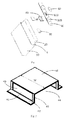
- Fig.1 depicts an examplary exploded view of a lithium ion battery according to a first embodiment of the present invention.
- the lithium ion battery includes a battery housing 10, a battery cell 20 received in the battery housing 10, an electrolyte (not shown) filled in the battery housing 10, and a battery cover 50 coupled to the battery housing 10.
- the battery cover 50 is formed with a positive electrode post and a negative electrode post (hereinafter both numubered as 550).
- the positive electrode post and the negative electrode post 550 are electrically connected to a positive electrode and a negative electrode (not shown) of the battery cell 20 via a conductive connector 30, respectively.
- the battery cover 50 defines a pressure relief hole 510 between the positive electrod post and the negative electrode post 550.
- the pressure relief hole 510 is sealed with a pressure relief plate 60.
- the pressure relief plate 60 and the pressure relief hole 510 constitute a pressure relief valve.
- the pressure relief plate 60 is made from a same metal material as that of the battery cover 50, so as to avoid formation of an electrolytic cell with surrounding air or electrolyte due to potential difference between different kinds of metals and reduce the risk of corrosion reaction.
- the prssure relief palte 60 is made from one of aluminum, aluminum alloy, nickel, nickel alloy or stainless steel. The prssure relief palte 60 has desirable ductility, and will not burst out when break to release the pressure.
- the prssure relief palte 60 is coated with or bonded with a layer of corrosion-resistant material, such as PE and/or PP, so as to prevent the prssure relief palte 60 from being corroded by the electrolyte.
- the prssure relief palte 60 is provided with a weakened line or a weakened area. The weakened line or the weakened area will first break when the pressure in the lithium ion battery exceeds a predetermined value, so as to control the break position of the prssure relief palte 60.
- the threshold value of the pressure of the pressure relief palte 60 can bear is about 0.3 ⁇ 1.2 Mpa.
- the lithium ion battery includes a safety device 40 fixed to the pressure relief valve.
- the safety device 40 can be disposed on a lower surface of the battery cover 50 facing the battery cell 20 (as shown in Fig. 1 ), and is seated between the battery cover 50 and the battery cell 20. According to one embodiment of the present invention, along a direction from the battery cover 50 to the battery cell 20, the safety device 40 is disposed just blow the pressure relief plate 60.
- the safety device 40 includes a shielding plate 48 facing the pressure relief valve, a side wall 49, a connecting porition 42, and an air flow channel structure 41.
- the shielding plate 48 covers the lower portion of the pressure relief plate 60, and a projected area of the shielding plate 48 on the pressure relief valve is no less than the area of the pressure relief valve, so as to prevent the ejected sparks from the front side effectively, and reflect the sparks to change the movement path and ejection speed of the sparks.
- the shileding plate 48 does not define any through hole which can act as the air flow channel.
- the air flow channel structure is only defined in the side wall 49, so as to fully block the sparks from the front side, and reflect the sparks to change the movement path and the ejection speed of the sparks.
- the side wall 49 is substantially vertically or obliquely disposed on the shileding plate 48, and extends from the shielding plate 48 to the battery cover 50.
- the side wall 49 can be continuously disposed along one edge of the shileding plate 48 (as shown in Figs. 6 , 7 , 9,10 ), or can be discontinuously disposed along one edge of the shileding plate 48 (as shown in Figs. 2 , 5 , 8 ). In the embodiment as shown in Fig. 2 , the side wall 49 is discontinuously disposed along one edge of the shileding plate 48.
- the side wall 49 includes two lateral plates substaintially vertically or obliquely disposed on the shileding plate 48.
- a connecting portion 42 is disposed at one end of the side wall 49 and is spaced from the shielding plate 48.
- the connecting portion 42 is fixed to the battery cover 50.
- the connecting portion 42 can be coupled to the battery cover 50 via stamping or molding, or can be fixed to the battery cover 50 via bonding, soldering, riveting, clamping, thread connecting, or snapping.
- the connecting portion 42 is fixed to the battery cover 50 via soldering, and the connecting tension therebetween is no less than 50N. If the connecting tension is too small, the safety device 40 may break off during the assembly of the lithium ion battery or in usage of the lithium ion battery due to vibration.
- the connecting portion 42 can also be omitted according to actual requirement.
- the side wall 49 can be directly fixed to the battery cover 50 via bonding, soldering or snapping.
- the air flow channel stucture 41 is defined in the side wall 49.
- the air flow channel structure 41 includes a first air flow channel 46 defined in a lateral plate of the side wall 49 and a second air flow channel 44 between the two lateral plates of the side wall 49.
- the first air flow channel 46 includes an opening structure defined in the lateral plate.
- the opening can be a rectangular hole shown in Fig. 2 or a hole having other shapes, so that the laterla plates substaintially presents as a frame.
- the total area of the opening structure is no less than half of that of the pressure relief hole 510. If the area is too small, when runaway occurs to the lithium ion battery, the gases in the lithium ion battery cannot be discharged timely.
- the second air channel 44 can be a gap between the two lateral plates of the side wall 49.
- the side wall 49 is continously disposed along one edge of the shielding plate 48.
- the second air flow channel 44 is a notch defined in the side wall 49. That is, a portion of the side wall 49 between the two lateral plates, as well as between the distal end of the side wall 49 and the shielding plate 48 is cut off.
- the safety device 40 can be made from metal or inorganic non-metallic ceramic material.
- the safety device 40 is made from metal meterial, such as aluminum, aluminum alloy, nickel, nickel alloy or stainless steel.
- the safety device 40 is made from a metal material as same as that of the battery cover 50, to prevent the battery housing 10 from forming an electrochemical cell under the condition of electrolyte and moist environment with different materials, and further effect the performance of the lithium ion battery.
- At least one surface of the safety device 40 facing the battery cell 20 is coated with a layer of electrically insulative material, for instance, teflon, epoxy, polyethylene terephthalate (PET), phenolic resin, polypropylene(PP) or ceramic.
- the electrically insulative layer is evenly coated on the surface of the metal and has a thickness of no less than 10 ⁇ m, which can achieve the effect of insulation and corrosion. If the thickness of the insulative layer is too small, the metal is exposed. If the surface of the safety device 40 has poor insulative property, the positive terminal and the negative terminal may short-circuit.
- the height H between the connecting portion 42 of the safety device 40 and the shielding plate 48 is at least 1mm less than the distance between the first surface of the battery cover 50 (for instance a lower surface of the battery cover 50) and the upper surface of the battery cell 20. If the height H is too large, the shielding plate 48 may press the positive plate and the negative plate in the battery cell 20, which may lead to deformation of the positive plate and the negative plate and even short-circuit the positive plate and the negative plate.
- the length L between the two lateral plates 49 of the safety device is at least 1mm less than the minimum distance between the positive tab and the negative tab.
- the width W of the safety device 40 is at least 1mm less than the distance between the two inner surfaces of the battery housing 10. If the width W is too large, the assembly of the battery cover 50 and the battery housing is affected.
- the solid spark particles burst out move along a straight line.
- the solid spark particles burst out together with the gases arrive at the safety device 40, the solid spark particles are blocked by the shielding plate 48 of the safety device 40 and reflected back into the battery housing 10, thereby preventing the high temperature solid spark particles from ejecting out of the lithium ion battery with the high speed gases and igniting at the outside of the lithium ion battery.
- the high speed gases will change the movement path and flow out via the first air flow channel 46, the second air flow channel 44 at the lateral side of the safety device 40, thereby lowering the speed of the gas flowing out of the lithium ion battery, reducing the distance of the gas bursting out of the lithium ion battery, reducing the contact area of the gas and the surrounding air, and reducing the risk of the ignition of the inflammable gases.
- the gases bursting out of the lithium ion battery with reduced ejection speed can reduce the risk of the ignition of the inflammable gases due to contact with other materials.
- the safety device 40 is provided with a shielding plate 48 seperated from the first air flow channel 46 and the second air flow channel 44.
- the shileding plate 48 can effectively block the solid spark particles.
- the gases can be dischaged via the first air flow channel 46 and the second air flow channel 44 at a lateral side of the safety device 40. Consequently, risk of explosion due to high interal pressure caused by inadequate exhaust efficiency is reduced.
- the safety device 40 can seperate the high speed gas, such as inflammable gas and electrolyte steam, from the solid spark particles, thereby preventing the inflammable gas and the electrolyte steam from bursting out together with the solid spark particles and mixing with the surrounding air afar from the pressure relief valve and igniting.
- the high speed gas such as inflammable gas and electrolyte steam
- Filtration of the solid spark particles can effectively change the possible ignition manner of the lithium ion battery from being ignited by sparks to autogenously igniting of the gas. Physically, the temperature for igniting by sparks is less than 60°C, while the temperature for autogenous ignition of the gas is higher than 450°C. Therefore, safety performance of the lithium ion battery is improved remarkably.
- the shielding plate 48 is seperated from the first air flow channel 46 and the second air flow channel 44.
- the shielding plate 48 is located in the path of ejected gases and can effectively block the solid spark particles.
- the first air flow channel 46 and the second air flow channel 44 at a lateral side of the safety device 40 will not be directly impacted by the solid spark particles, or only be directly impacted by a small amount of the solid spark particles. Therefore, the sizes and shapes of the first air flow channel 46 and the second air flow channel 44 can be selected in a wide range, and the first air flow channel 46 and the second air flow channel 44 can hardly be blocked by the solid spark particles.
- Fig. 5 depicts an examplary perspective view of a safety device according to another embodiment of the present invention.
- the safety device as illustrated in Fig. 5 is almost the same as that illustrated in Fig. 2 except that, in the embodiment as shown in Fig. 5 , the first air flow channel 46 of the safety device includes a number of through holes in the side wall thereof, i.e. a through holes array.
- each through hole has an area no less than 1mm 2
- the total area of the through holes is no less than 1/2 of the area of the pressure relief hole 510.
- the safety device as illustrated in Fig. 5 has a balanced sparks blocking effect and air discharging rate.
- Fig. 6 depicts an exemplary perspective view of a safety device according to another embodiment of the present invention.
- the safety device as illustrated in Fig. 6 is almost the same as that illustrated in Fig. 5 except that, the side wall 49 is continiously arranged along one edge of the shielding plate 48, and the second air flow channel 44 includes a number of through holes defined in the side wall.
- the first air flow channel 46 and the second air flow channel 44 each includes a number of through holes defined in the side wall.
- the shape of the through hole can be a circle, a diamond, a square, an oval or racetrack.
- Each through hole has an area no less than 1mm 2 .
- the total area of the through holes is no less than half of the area of the pressure relief hole 510.
- the first air flow channel 46 and the second air flow channel 44 can filter the sparks passing through the first air flow channel 46 and the second air flow channel 44 and seperate the sparks from the inflammable gas effectively.
- Fig. 7 depicts an exemplary perspective view of a safety device according to another embodiment of the present invention.
- the safety device as illustrated in Fig. 7 is almost the same as that illustrated in Fig. 2 except that, in the embodiment as shown in Fig. 7 , the side wall 49 of the safety device continiously disposed along one edge of the shielding plate 48, and the second air flow channel 44 includes a number of through holes defined in the side wall 49.
- each through hole has an area no less than 1mm 2 .
- the total area of the through holes is no less than half of the area of the pressure relief hole 510.
- the safety device as illustrated in Fig. 7 has a balanced sparks blocking effect and air discharging rate.
- Fig. 8 depicts an exemplary perspective view of a safety device according to another embodiment of the present invention.
- the safety device illustrated in Fig. 8 is almost the same as that illustrated in Fig. 2 except that, in the embodiment as shown in Fig. 8 , the shielding plate 48 defines a number of through holes.
- the through holes in the shielding plate 48 allow the pass of gases and prohibit the pass of the high temperature solid particles.
- each through hole has an area less than 1mm 2 , thereby increasing the channel area of allowing the pass of the gas and reducing accumulation of pressure in the battery housing 10. If the area of a single through hole is too large, sparks having small diameters may pass through the through hole, which will affect the blocking effect.
- Fig. 9 depicts an examplary perspective view of a safety device according to another embodiment of the present invention.
- the safety device as illustrated in Fig. 9 is almost the same as that illustrated in Fig. 7 except that, in the embodiment as illustrated in Fig. 9 , the shielding plate 48 defines a number of through holes.
- the through holes in the shielding plate 48 allow the pass of the gases and prohibit the pass of the high temperature solid particles.
- each through hole has an area less than 1mm 2 . thereby increasing the channel area and allowing the pass of the gases and reducing accumulation of pressure in the battery housing 10.
- the safety device shown in Fig. 9 has a balanced sparks blocking effect and air discharging rate.
- Fig. 10 depicts an examplary perspective view of a safety device according to another embodiment of the present invention.
- the safety device illustrated in Fig. 10 is almost the same as that illustrated in Fig. 2 except that, the side wall 49 of the safety device shown in Fig. 10 is continiously arranged along one edge of the shielding plate 48, and the second air flow channel 44 includes an opening structure defined in the side wall 49, such that the side wall 49 substaintially presents a frame shape.
- the safety device shown in Fig. 10 can strengthen the strength of the safety device.
- Fig. 12 depicts an examplary explosed view of a lithium ion battery according to another embodiment of the present invention.
- the lithium ion battery as shown in Fig. 12 is almost the same as that illustrated in Fig. 1 except that, the lithium ion battery as shown in Fig. 12 includes a second safety device 70.
- the second safety device 70 and the first safety device 40 are disposed at two sides of the battery cover 50 and cover the pressure relief plate 60 respectively.
- the second safety device 70 has a same structure as any one of the safety devices 40 have been detailed in the embodiments as previously described.
- the air flow channel of the second safety device 70 can also be defined in the shielding plate 48 only.
- the first safety device 40 and the second safety device 70 both can protect the battery cell 20, thereby keeping the air channel smooth, enhancing the blocking effect to the solid spark particles, seperating the solid spark particles (i.e. inflammable gas) effectively, and ensuring the safety performace of the battery cell 20.
- the lithium ion batteries are square lithium ion batteries.
- the lithium ion battery can be any one lithium ion battery having other shapes, for instance a prismatic lithium ion battery or a cylindrical lithium ion battery.
- the safety device in accordance with the present invention can also be used in other lithium ion batteries.
- the safety device can be coupled to the battery housing 10 in a similar manner as described above, or be coupled to the battery housing 10 and the battery cover 50 respectively.
Abstract
Description
- The present patent application claims priority to Chinese patent application number
CN 201410636841.1 filed on Nov. 11, 2014 - The present invention relates to lithium ion batteries and, more particularly, relates to a lithium ion battery and a lithium ion battery pack having desirable safety performance.
- At present, lithium ion batteries are becoming increasingly popular in electric vehicles and grid energy storage. Accordingly, more and more attention has been paid to the safety performance of lithium ion batteries. Generally, safety accidents of lithium ion batteries are caused by thermal runaway.
- When thermal runaway occurs to a lithium in battery, heat generated by active materials in a lithium ion battery may reach hundreds of Joule/g, which may lead to intense oxidation -reduction reaction of the active materials and the electrolyte and further generate a large amount of flammable gases. The flammable gases generated may lead to sharp increase of pressure in the lithium ion battery and break the explosion-proof valve to generate high speed gas flow. The flammable gases ejecteded will mix with the surrounding air. At the same time, during the ejection of the flammable gases from the lithium ion battery, a large amount of high temperature solid parciles will be brought out. The solid particles may ignite the mixture of the flammable gases and the surrounding air, which may lead to ignition even explosion of the lithium ion battery.
- Chinese patent publication number
CN 103474599A discloses a lithium ion battery and a lithium ion battery pack having desirable safety performance. The lithium ion battery is equipped with a mesh member which defines a number of through holes extending therethrough. The mesh member can filter the high temperature solid particles, to seperate the high temperature solid particles from the imflammable gases. However, the mesh member disclosed inCN 103474599A at least has the following disadvantages. When thermal runaway occurs to a lithium ion battery, the mixture of the imflammable gases and the high temperature solid particles in the lithium ion battery will be ejected quickly. The through holes are only defined in the top section of the mesh member in the path of the gas ejection. If the through hole of the mesh member is too large, the high speed gas flow brings the high temperature solid particles out, which may lead to ignition or explosion of the lithium ion battery. In addition, if the through hole is too large, the stregnth of the mesh member is reduced, and the mesh member is apt to break under the impact of the high speed gas flow carrying the high temperatuer solid particles. If the through hole is too small, the gases cannot be discharged from the lithium ion battery timely. In addition, when thermal runaway occurs to the lithium ion battery, the melted plastic components, the solid pariticles in the gas flow or the melt slage may block the through holes, which will lead to sharp increase of pressure in the lithium ion battery and even explosion of the lithium ion battery. - In view of the foregoing, what is needed, therefore, is to provide a lithium ion battery and a lithium ion battery pack having desirable safety performance.
- One object of the present invention is to provide a lithium ion battery and a lithium ion battery pack having desirable safety performance.
- According to one embodiment of the present invention, a lithium ion battery having desirable safety performance is provided. The lithium ion battery includes a battery housing, a battery cover assembled to the battery housing, and a pressure relief valve coupled to the battery housing and/or battery cover. The battery housing and/or the battey cover is coupled with a first safety device fixed to the pressure relief valve. The first safety device includes a shielding plate facing the pressure relief valve, a side wall and an air flow channel structure. The side wall extends from the shielding plate and connects with the battery housing or the battery cover, while the air flow channel structure is defined in the side wall.
- According to one aspect of the present invention, the air flow channel structure is only defined in the side wall.
- According to one aspect of the present invention, the air flow channel includes at least one opening, at least one through holes array, or at least one notch defined in the sidewall.
- According to one aspect of the present invention, the air flow channel structure is a through holes array, each through hole in the through holes array has an area no less than 1mm2.
- According to one aspect of the present invention, the shielding plate defines a number of through holes, and each through hole in the shielding plate has an area less than 1mm2.
- According to one aspect of the present invention, the air flow channel structure includes a first air flow channel and a second air flow channel spaced apart from each other in the side wall. The first air flow channel is configured as an opening, a through holes array or a notch. The second air flow channel is configured as an opening, a through holes array or a notch. The first air flow channel and the second air flow channel have different structures.
- According to one aspect of the present invention, the pressure relief valve defines pressure relief hole, and a total area of the air flow channel structure is no less than 1/2 of an area of the pressure relief hole.
- According to one aspect of the present invention, the first air flow channel or the second air flow channel is a through holes array, each through hole in the through holes array has an area no less than 1mm2.
- According to one aspect of the present invention, the lithium ion battery also includes a battery cell received in the battery housing. The first safety device is disposed between the battery cell and the battery cover. The first safety device has a height at least 1mm less than a minimum distance between a surface of the battery cover facing the battery cell and the battery cell, a width no less 1 mm than a distance between two lateral inner surfaces of the battery housing , and a length at least 1mm less than a minimum distance between positive and negative tabs of the battery cell.
- According to one aspect of the present invention, the first safety device includes a connecting portion formed at one end of the side wall and spaced apart from the shielding plate. The side wall is connected to the battery housing or the battery cover via the connecting portion.
- According to one aspect of the present invention, the lithium ion battery further includes a second safety device. The first safety device and the second safety device are seated at two sides of the pressure relief valve and cover the pressure relief valve, respectively. The second safety device includes a shielding plate facing the pressure relief valve, a side wall and an air flow channel structure. The side wall extends from the shielding plate and connects with the battery housing or the battery cover. The air flow channel structure is defined in the side wall and/or the shielding plate.
- According to one aspect of the present invention, the first safety device is made from metal or inorganic non-metallic ceramic.
- According to one aspect of the present invention, a surface of the first safety device is formed with a layer of teflon, epoxy resin, polyethylene terephthalate, polypropylene, phenolic resin or ceramic.
- According to one embodiment of the present invention, a lithium ion battery pack is provided. The lithium ion battery pack includes a number of lithium ion batteries described previously connected in parallel and /or series.
- According to the embodiments of the present invention, the side wall of the safety device of the lithium ion battery or lithium ion battery pack defines an air flow channel structure. The shielding plate of the safety device is seperated from the air flow channel structure. The shielding plate can block the solid spark particles effectively. The air flow channel structure on the side wall of the safety device can dischage the gas effectively. Therefore, explosion risk caused by pressure increase due to low exhaust efficiency is reduced, and the safety performance of the lithium ion battery is improved remarkably. At the same time, the shielding plate and the air flow channel structure at one side of the safety device can change the direction of the gas flow, so as to prevent the vertically ejected high speed gases from extensively mixing with the surrounding air and further improve the safety performance of the lithium ion battery.
- Other advantages and novel features will be drawn from the following detailed description of preferred embodiments with the attached drawings. The accompanying drawings, which are incorporated in and constitute a part of this specification, illustrate embodiments of the present invention and, together with a general description of the invention given above, and the detailed description of the embodiments given below, serve to explain the principles of the invention:
-
-
Fig. 1 depicts an exemplary exploded view of a lithium ion battery according to a first embodiment of the present invention; -
Fig. 2 depicts an examplary enlarged view of a safety device of the lithium ion battery as shown inFig. 1 ; -
Fig. 3 depicts an examplary top view of the safety device as shown inFig. 2 ; -
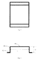
Fig. 4 depicts an examplary front view of the safety device as shown inFig. 2 ; -
Fig. 5 to 11 depict a number of examplary perspective views of various safety devices according to other embodiments of the present invention; and -
Fig. 12 depicts an examplary exploded view of a lithium ion battery according to another embodiment of the present invention. - Example embodiments of the present invention will now be described more fully hereinafter with reference to the accompanying drawings, in which some, but not all embodiments of the invention are shown. Indeed, the invention may be embodied in many different forms and should not be construed as limited to the embodiments set forth herein; rather, these embodiments are provided so that this disclosure will satisfy applicable legal requirements. Like reference numerals refer to like elements throughout.
-
Fig.1 depicts an examplary exploded view of a lithium ion battery according to a first embodiment of the present invention. The lithium ion battery includes abattery housing 10, abattery cell 20 received in thebattery housing 10, an electrolyte (not shown) filled in thebattery housing 10, and abattery cover 50 coupled to thebattery housing 10. Thebattery cover 50 is formed with a positive electrode post and a negative electrode post (hereinafter both numubered as 550). The positive electrode post and the negative electrode post 550 are electrically connected to a positive electrode and a negative electrode (not shown) of thebattery cell 20 via aconductive connector 30, respectively. Thebattery cover 50 defines apressure relief hole 510 between the positive electrod post and the negative electrode post 550. Thepressure relief hole 510 is sealed with apressure relief plate 60. Thepressure relief plate 60 and thepressure relief hole 510 constitute a pressure relief valve. - More specifically, the
pressure relief plate 60 is made from a same metal material as that of thebattery cover 50, so as to avoid formation of an electrolytic cell with surrounding air or electrolyte due to potential difference between different kinds of metals and reduce the risk of corrosion reaction. In the embodiment as shown inFig. 1 , theprssure relief palte 60 is made from one of aluminum, aluminum alloy, nickel, nickel alloy or stainless steel. Theprssure relief palte 60 has desirable ductility, and will not burst out when break to release the pressure. According to one embodiment of the present invention, theprssure relief palte 60 is coated with or bonded with a layer of corrosion-resistant material, such as PE and/or PP, so as to prevent theprssure relief palte 60 from being corroded by the electrolyte. According to another embodiment of the present invention, theprssure relief palte 60 is provided with a weakened line or a weakened area. The weakened line or the weakened area will first break when the pressure in the lithium ion battery exceeds a predetermined value, so as to control the break position of theprssure relief palte 60. According to one embodiment of the present invention, the threshold value of the pressure of thepressure relief palte 60 can bear is about 0.3∼1.2 Mpa. - Referring to
Fig. 1 , the lithium ion battery includes asafety device 40 fixed to the pressure relief valve. Thesafety device 40 can be disposed on a lower surface of thebattery cover 50 facing the battery cell 20 (as shown inFig. 1 ), and is seated between thebattery cover 50 and thebattery cell 20. According to one embodiment of the present invention, along a direction from thebattery cover 50 to thebattery cell 20, thesafety device 40 is disposed just blow thepressure relief plate 60. - Specifically, referring to
Figs. 2 to 4 , thesafety device 40 includes a shieldingplate 48 facing the pressure relief valve, aside wall 49, a connectingporition 42, and an airflow channel structure 41. - According to one embodiment of the present invention, the shielding
plate 48 covers the lower portion of thepressure relief plate 60, and a projected area of the shieldingplate 48 on the pressure relief valve is no less than the area of the pressure relief valve, so as to prevent the ejected sparks from the front side effectively, and reflect the sparks to change the movement path and ejection speed of the sparks. In the embodiment as shown inFig. 2 , theshileding plate 48 does not define any through hole which can act as the air flow channel. In other words, the air flow channel structure is only defined in theside wall 49, so as to fully block the sparks from the front side, and reflect the sparks to change the movement path and the ejection speed of the sparks. - The
side wall 49 is substantially vertically or obliquely disposed on theshileding plate 48, and extends from the shieldingplate 48 to thebattery cover 50. Theside wall 49 can be continuously disposed along one edge of the shileding plate 48 (as shown inFigs. 6 ,7 ,9,10 ), or can be discontinuously disposed along one edge of the shileding plate 48 (as shown inFigs. 2 ,5 ,8 ). In the embodiment as shown inFig. 2 , theside wall 49 is discontinuously disposed along one edge of theshileding plate 48. Theside wall 49 includes two lateral plates substaintially vertically or obliquely disposed on theshileding plate 48. - A connecting
portion 42 is disposed at one end of theside wall 49 and is spaced from the shieldingplate 48. The connectingportion 42 is fixed to thebattery cover 50. The connectingportion 42 can be coupled to thebattery cover 50 via stamping or molding, or can be fixed to thebattery cover 50 via bonding, soldering, riveting, clamping, thread connecting, or snapping. According to a preferable embodiment of the present invention, the connectingportion 42 is fixed to thebattery cover 50 via soldering, and the connecting tension therebetween is no less than 50N. If the connecting tension is too small, thesafety device 40 may break off during the assembly of the lithium ion battery or in usage of the lithium ion battery due to vibration. As shown inFig. 11 , in actual use, the connectingportion 42 can also be omitted according to actual requirement. In this case, theside wall 49 can be directly fixed to thebattery cover 50 via bonding, soldering or snapping. - The air flow channel stucture 41 is defined in the
side wall 49. In the embodiment as shown inFig. 2 , the airflow channel structure 41 includes a firstair flow channel 46 defined in a lateral plate of theside wall 49 and a secondair flow channel 44 between the two lateral plates of theside wall 49. The firstair flow channel 46 includes an opening structure defined in the lateral plate. The opening can be a rectangular hole shown inFig. 2 or a hole having other shapes, so that the laterla plates substaintially presents as a frame. The total area of the opening structure is no less than half of that of thepressure relief hole 510. If the area is too small, when runaway occurs to the lithium ion battery, the gases in the lithium ion battery cannot be discharged timely. When the gas pressure in the lithium ion battery exceeds the strength of the battery housing, the battery housing may break and lead to explosion. Thesecond air channel 44 can be a gap between the two lateral plates of theside wall 49. In other words, theside wall 49 is continously disposed along one edge of the shieldingplate 48. The secondair flow channel 44 is a notch defined in theside wall 49. That is, a portion of theside wall 49 between the two lateral plates, as well as between the distal end of theside wall 49 and the shieldingplate 48 is cut off. - In actual use, the
safety device 40 can be made from metal or inorganic non-metallic ceramic material. According to one embodiment of the present invention, thesafety device 40 is made from metal meterial, such as aluminum, aluminum alloy, nickel, nickel alloy or stainless steel. Thesafety device 40 is made from a metal material as same as that of thebattery cover 50, to prevent thebattery housing 10 from forming an electrochemical cell under the condition of electrolyte and moist environment with different materials, and further effect the performance of the lithium ion battery. At least one surface of thesafety device 40 facing the battery cell 20 (such as one surface of thesafety device 40 afar from the pressure relief valve when thesafety device 40 is seated between thebattery cover 50 and thebattery cell 20; or one surface of thesafety device 40 facing the pressure relief valve when thesafety device 40 is seated at an outer side of the battery cover 50) is coated with a layer of electrically insulative material, for instance, teflon, epoxy, polyethylene terephthalate (PET), phenolic resin, polypropylene(PP) or ceramic. The electrically insulative layer is evenly coated on the surface of the metal and has a thickness of no less than 10µm, which can achieve the effect of insulation and corrosion. If the thickness of the insulative layer is too small, the metal is exposed. If the surface of thesafety device 40 has poor insulative property, the positive terminal and the negative terminal may short-circuit. - Referring to
Fig. 4 , in actual use, the height H between the connectingportion 42 of thesafety device 40 and the shieldingplate 48 is at least 1mm less than the distance between the first surface of the battery cover 50 (for instance a lower surface of the battery cover 50) and the upper surface of thebattery cell 20. If the height H is too large, the shieldingplate 48 may press the positive plate and the negative plate in thebattery cell 20, which may lead to deformation of the positive plate and the negative plate and even short-circuit the positive plate and the negative plate. The length L between the twolateral plates 49 of the safety device is at least 1mm less than the minimum distance between the positive tab and the negative tab. If the length L is too large, the tabs may interfer with the boundary of the shieldingplate 48 and thelateral plate 46, which may damage the tabs. As shown inFigs. 1 and 2 , the width W of thesafety device 40 is at least 1mm less than the distance between the two inner surfaces of thebattery housing 10. If the width W is too large, the assembly of thebattery cover 50 and the battery housing is affected. - In safety test of the lithium ion battery assembled in accordance with the embodiment as shown in
Fig. 1 , temperature in the lithium ion battery increases sharply and a large amount of gases are generated. In this case, thepressure relief plate 60 is ruptured and converted, to release the gases carrying the high temperature solid spark particles in the lithium ion battery. Due to thesafety device 40 is covered with apressure relief plate 60 at a below side thereof, the solid spark particles burst out are blocked by the shieldingplate 48 of thesafety device 40. The gases can be discharged out of thebattery housing 10 via the firstair flow channel 46 and the secondair flow channel 44, so as to maintain the pressure relief function. - In this case, the solid spark particles burst out move along a straight line. When the solid spark particles burst out together with the gases arrive at the
safety device 40, the solid spark particles are blocked by the shieldingplate 48 of thesafety device 40 and reflected back into thebattery housing 10, thereby preventing the high temperature solid spark particles from ejecting out of the lithium ion battery with the high speed gases and igniting at the outside of the lithium ion battery. At the same time, when the high speed gases arrive at thesafety device 40, due to the block of the shieldingplate 48 of thesafety device 40, the high speed gases will change the movement path and flow out via the firstair flow channel 46, the secondair flow channel 44 at the lateral side of thesafety device 40, thereby lowering the speed of the gas flowing out of the lithium ion battery, reducing the distance of the gas bursting out of the lithium ion battery, reducing the contact area of the gas and the surrounding air, and reducing the risk of the ignition of the inflammable gases. In addition, the gases bursting out of the lithium ion battery with reduced ejection speed can reduce the risk of the ignition of the inflammable gases due to contact with other materials. - Compared with Chinese patent publication number
CN 103474599A , according to one embodiment of the present invention, thesafety device 40 is provided with a shieldingplate 48 seperated from the firstair flow channel 46 and the secondair flow channel 44. Theshileding plate 48 can effectively block the solid spark particles. The gases can be dischaged via the firstair flow channel 46 and the secondair flow channel 44 at a lateral side of thesafety device 40. Consequently, risk of explosion due to high interal pressure caused by inadequate exhaust efficiency is reduced. At the same time, the flow direction of the gas can be changed via the shieldingplate 48 and the firstair flow channel 46, the secondair flow channel 44 at a lateral side of thesafety device 40, thereby preventing the high speed gas vertically ejecting out of the lithium ion battery and extensively mixing with the surrounding air. According to one embodiment of the present invention, thesafety device 40 can seperate the high speed gas, such as inflammable gas and electrolyte steam, from the solid spark particles, thereby preventing the inflammable gas and the electrolyte steam from bursting out together with the solid spark particles and mixing with the surrounding air afar from the pressure relief valve and igniting. Filtration of the solid spark particles can effectively change the possible ignition manner of the lithium ion battery from being ignited by sparks to autogenously igniting of the gas. Physically, the temperature for igniting by sparks is less than 60°C, while the temperature for autogenous ignition of the gas is higher than 450°C. Therefore, safety performance of the lithium ion battery is improved remarkably. - In addition, compared with Chinese patent publication number
CN103474599A , the shieldingplate 48 according to one embodiment of the present invention is seperated from the firstair flow channel 46 and the secondair flow channel 44. The shieldingplate 48 is located in the path of ejected gases and can effectively block the solid spark particles. The firstair flow channel 46 and the secondair flow channel 44 at a lateral side of thesafety device 40 will not be directly impacted by the solid spark particles, or only be directly impacted by a small amount of the solid spark particles. Therefore, the sizes and shapes of the firstair flow channel 46 and the secondair flow channel 44 can be selected in a wide range, and the firstair flow channel 46 and the secondair flow channel 44 can hardly be blocked by the solid spark particles. -
Fig. 5 depicts an examplary perspective view of a safety device according to another embodiment of the present invention. The safety device as illustrated inFig. 5 is almost the same as that illustrated inFig. 2 except that, in the embodiment as shown inFig. 5 , the firstair flow channel 46 of the safety device includes a number of through holes in the side wall thereof, i.e. a through holes array. According to a preferred embodiment of the present invention, each through hole has an area no less than 1mm2, and the total area of the through holes is no less than 1/2 of the area of thepressure relief hole 510. The safety device as illustrated inFig. 5 has a balanced sparks blocking effect and air discharging rate. -
Fig. 6 depicts an exemplary perspective view of a safety device according to another embodiment of the present invention. The safety device as illustrated inFig. 6 is almost the same as that illustrated inFig. 5 except that, theside wall 49 is continiously arranged along one edge of the shieldingplate 48, and the secondair flow channel 44 includes a number of through holes defined in the side wall. In other words, the firstair flow channel 46 and the secondair flow channel 44 each includes a number of through holes defined in the side wall. The shape of the through hole can be a circle, a diamond, a square, an oval or racetrack. Each through hole has an area no less than 1mm2. The total area of the through holes is no less than half of the area of thepressure relief hole 510. If the area of a single through hole is too small, the area of the air flow channel is hard to meet the requirement of actual use. In addition, the molten plastic components and solid particles are apt to block the through holes, which may cause the gases cannot be dischaged timely and high pressure in the lithium ion battery. The firstair flow channel 46 and the secondair flow channel 44 can filter the sparks passing through the firstair flow channel 46 and the secondair flow channel 44 and seperate the sparks from the inflammable gas effectively. -
Fig. 7 depicts an exemplary perspective view of a safety device according to another embodiment of the present invention. The safety device as illustrated inFig. 7 is almost the same as that illustrated inFig. 2 except that, in the embodiment as shown inFig. 7 , theside wall 49 of the safety device continiously disposed along one edge of the shieldingplate 48, and the secondair flow channel 44 includes a number of through holes defined in theside wall 49. According to one embodiment of the present invention, each through hole has an area no less than 1mm2. The total area of the through holes is no less than half of the area of thepressure relief hole 510. The safety device as illustrated inFig. 7 has a balanced sparks blocking effect and air discharging rate. -
Fig. 8 depicts an exemplary perspective view of a safety device according to another embodiment of the present invention. The safety device illustrated inFig. 8 is almost the same as that illustrated inFig. 2 except that, in the embodiment as shown inFig. 8 , the shieldingplate 48 defines a number of through holes. The through holes in the shieldingplate 48 allow the pass of gases and prohibit the pass of the high temperature solid particles. According to one embodiment of the present invention, each through hole has an area less than 1mm2, thereby increasing the channel area of allowing the pass of the gas and reducing accumulation of pressure in thebattery housing 10. If the area of a single through hole is too large, sparks having small diameters may pass through the through hole, which will affect the blocking effect. -
Fig. 9 depicts an examplary perspective view of a safety device according to another embodiment of the present invention. The safety device as illustrated inFig. 9 is almost the same as that illustrated inFig. 7 except that, in the embodiment as illustrated inFig. 9 , the shieldingplate 48 defines a number of through holes. The through holes in the shieldingplate 48 allow the pass of the gases and prohibit the pass of the high temperature solid particles. According to one embodiment of the present invention, each through hole has an area less than 1mm2. thereby increasing the channel area and allowing the pass of the gases and reducing accumulation of pressure in thebattery housing 10. The safety device shown inFig. 9 has a balanced sparks blocking effect and air discharging rate. -
Fig. 10 depicts an examplary perspective view of a safety device according to another embodiment of the present invention. The safety device illustrated inFig. 10 is almost the same as that illustrated inFig. 2 except that, theside wall 49 of the safety device shown inFig. 10 is continiously arranged along one edge of the shieldingplate 48, and the secondair flow channel 44 includes an opening structure defined in theside wall 49, such that theside wall 49 substaintially presents a frame shape. The safety device shown inFig. 10 can strengthen the strength of the safety device. -
Fig. 12 depicts an examplary explosed view of a lithium ion battery according to another embodiment of the present invention. The lithium ion battery as shown inFig. 12 is almost the same as that illustrated inFig. 1 except that, the lithium ion battery as shown inFig. 12 includes asecond safety device 70. Thesecond safety device 70 and thefirst safety device 40 are disposed at two sides of thebattery cover 50 and cover thepressure relief plate 60 respectively. Thesecond safety device 70 has a same structure as any one of thesafety devices 40 have been detailed in the embodiments as previously described. In addition, the air flow channel of thesecond safety device 70 can also be defined in the shieldingplate 48 only. During the safety test of thebattery cell 20, thefirst safety device 40 and thesecond safety device 70 both can protect thebattery cell 20, thereby keeping the air channel smooth, enhancing the blocking effect to the solid spark particles, seperating the solid spark particles (i.e. inflammable gas) effectively, and ensuring the safety performace of thebattery cell 20. - It should be understood that, in the embodiments as illustrated, the lithium ion batteries are square lithium ion batteries. However, there is no particular limitation to the shapes of the lithium ion batteries. The lithium ion battery can be any one lithium ion battery having other shapes, for instance a prismatic lithium ion battery or a cylindrical lithium ion battery. In addition, in the embodiments as illustated, although the present invention has been described in connojunction with the pressure relief plat, the safety device in accordance with the present invention can also be used in other lithium ion batteries. In addition, the safety device can be coupled to the
battery housing 10 in a similar manner as described above, or be coupled to thebattery housing 10 and thebattery cover 50 respectively. - Many modifications and other embodiments of the inventions set forth herein will come to mind to one skilled in the art to which these inventions pertain having the benefit of the teachings presented in the foregoing descriptions and the associated drawings. Therefore, it is to be understood that the inventions are not to be limited to the specific embodiments disclosed and that modifications and other embodiments are intended to be included within the scope of the appended claims. Moreover, although the foregoing descriptions and the associated drawings describe example embodiments, it should be appreciated that alternative embodiments without departing from the scope of the appended claims. Although specific terms are employed herein, they are used in a generic and descriptive sense only and not for purposes of limitation.
Claims (14)
- A lithium ion battery, comprising:a battery housing (10):a battery cover (50) assembled to the battery housing (10); anda pressure relief valve (60,510) coupled to the battery housing (10) and/or battery cover (50);charaterized in that the battery housing (10) and/or the battey cover (50) is assembled with a first safety device (40) fixed to the pressure relief valve (60,510), the first safety device (40) comprises a shielding plate (48) facing the pressure relief valve (60,510), a side wall (49) and an air flow channel structure (41), the side wall (49) extends from the shielding plate (48) and connects with the battery housing (10) or the battery cover (50), and the air flow channel structure (41) is defined in the side wall (49).
- The lithium ion battery of claim 1, charaterized in that the air flow channel structure (41) is only defined in the side wall (49).
- The lithium ion battery of claim 1 or 2, charaterized in that the air flow channel structure (41) comprises at least one opening, at least one through holes array, or at least one notch defined in the side wall (49).
- The lithium ion battery of at least one of claims 1 to 3, charaterized in that the air flow channel structure (41) is a through holes array, and each through hole in the through holes array has an area no less than 1mm2.
- The lithium ion battery of at least one of claims 1 to 4, charaterized in that the shielding plate (48) defines a plurality of through holes, and each through hole in the shielding plate (48) has an area less than 1mm2.
- The lithium ion battery of at least one of claims 1 to 5, charaterized in that the air flow channel structure (41) comprises a first air flow channel (46) and a second air flow channel (44) spaced apart from each other in the side wall (49), the first air flow channel (46) is configued as an opening, a through holes array, or a notch, the second air flow channel (44) is configured as an opening, a through holes array, or a notch, the first air flow channel (46) and the second air flow channel (44) have different structures.
- The lithium ion battery of at least one of claims I to 6, charaterized in that the pressure relief valve (60,510) defines a pressure relief hole (510), and total area of the air flow channel structure (41) is no less than 1/2 of the area of the pressure relief hole (510).
- The lithium ion battery of at least one of claims 1 to 7, charaterized in that the first air flow channel (46) or the second air flow channel (44) is a through holes array, each through hole in the through holes array has an area no less than 1mm2.
- The lithium ion battery of at least one of claims 1 to 8, charaterized in that the lithium ion battery further comprises a battery cell (20) received in the battery housing (10), the first safety device (40) is disposed between the battery cell (20) and the battery cover (50), the first safety device (40) has a height at least 1mm less than a minimum distance between a surface of the battery cover (50) facing the battery cell (20) and the battery cell (20), a width no less 1mm than a distance between two lateral inner surfaces of the battery housing (10), and a length at least 1mm less than a minimum distance between positive and negative tabs of the battery cell (20).
- The lithium ion battery of at least one of claims 1 to 9, charaterized in that the first safety device (40) comprises a connecting portion (42) formed at one end of the side wall (49) and spaced apart from the shielding plate (48), and the side wall (49) is connected to the battery housing (10) or the battery cover (50) via the connecting portion (42).
- The lithium ion battery of at least one of claims 1 to 10, charaterized in that the lithium ion battery further comprises a second safety device (70), the first safety device (40) and the second safety device (70) are seated at two sides of the pressure relief valve (60,510) and cover the pressure relief valve (60,510) respectively, the second safety device (70) comprises a shielding plate (48) facing the pressure relief valve (60,510), a side wall (49) and an air flow channel structure (41), the side wall (49) extends from the shielding plate (48) and connects with the battery housing (10) or the battery cover (50), and the air flow channel structure (41) is defined in the side wall (49) and/or the shielding plate (48).
- The lithium ion battery of at least one of claims 1 to 11, charaterized in that the first safety device (40) is made from metal or inorganic non-metallic ceramic.
- The lithium ion battery of at least one of claims 1 to 12, charaterized in that a surface of the first safety device (40) is formed with a layer of teflon, phenolic resin, polyethylene terephthalate, polypropylene, epoxy resin or ceramic.
- A lithium ion battery pack, comprising a plurality of lithium ion batteries according to at least one of claims 1 to 13 connected in parallel and/or in series.
Applications Claiming Priority (1)
| Application Number | Priority Date | Filing Date | Title |
|---|---|---|---|
| CN201410636841.1A CN104319360B (en) | 2014-11-11 | 2014-11-11 | Lithium ion battery and battery pack |
Publications (2)
| Publication Number | Publication Date |
|---|---|
| EP3021379A1 true EP3021379A1 (en) | 2016-05-18 |
| EP3021379B1 EP3021379B1 (en) | 2019-07-03 |
Family
ID=52374565
Family Applications (1)
| Application Number | Title | Priority Date | Filing Date |
|---|---|---|---|
| EP15177802.4A Active EP3021379B1 (en) | 2014-11-11 | 2015-07-22 | Lithium ion battery and lithium ion battery pack |
Country Status (4)
| Country | Link |
|---|---|
| US (2) | US9806312B2 (en) |
| EP (1) | EP3021379B1 (en) |
| JP (1) | JP2016096129A (en) |
| CN (1) | CN104319360B (en) |
Cited By (2)
| Publication number | Priority date | Publication date | Assignee | Title |
|---|---|---|---|---|
| CN107320871A (en) * | 2017-07-11 | 2017-11-07 | 公安部天津消防研究所 | A kind of lithium ion battery case special gas extinguishing device and fire extinguishing implementation method |
| DE102022001413A1 (en) | 2022-04-25 | 2022-06-09 | Mercedes-Benz Group AG | Battery cell housing for a battery cell of a battery module, and battery module |
Families Citing this family (33)
| Publication number | Priority date | Publication date | Assignee | Title |
|---|---|---|---|---|
| CN108886127B (en) * | 2016-03-31 | 2021-07-06 | 株式会社丰田自动织机 | Electricity storage device |
| US10811650B2 (en) | 2016-06-29 | 2020-10-20 | Sanyo Electric Co., Ltd. | Secondary battery |
| US11211668B2 (en) * | 2016-08-15 | 2021-12-28 | Kabushiki Kaisha Toyota Jidoshokki | Power storage apparatus |
| JP6794736B2 (en) * | 2016-09-21 | 2020-12-02 | 株式会社豊田自動織機 | Power storage device |
| JP6750438B2 (en) * | 2016-09-30 | 2020-09-02 | 三洋電機株式会社 | Prismatic secondary battery |
| US11264673B2 (en) * | 2016-12-27 | 2022-03-01 | Panasonic Intellectual Property Management Co., Ltd. | Sealing body and nonaqueous electrolyte secondary battery |
| CN106784493A (en) * | 2017-01-20 | 2017-05-31 | 江门市大长江集团有限公司 | Battery of electric vehicle and electric motor car |
| KR102058197B1 (en) | 2017-09-18 | 2020-01-22 | 주식회사 엘지화학 | Battery case, battery pack including the same, and vehicle including the same |
| US11081738B2 (en) | 2018-03-06 | 2021-08-03 | International Business Machines Corporation | Containment heatsink for packaged battery cells |
| US10641835B2 (en) * | 2018-03-15 | 2020-05-05 | Ascending Energy Inc. | Health monitoring and safety protection for lithium ion battery modules and applications |
| CN108598326B (en) * | 2018-06-11 | 2023-11-28 | 超威电源集团有限公司 | Lithium ion battery and battery pack |
| DE102018210151A1 (en) * | 2018-06-21 | 2019-12-24 | Bayerische Motoren Werke Aktiengesellschaft | Vehicle with a high-voltage battery |
| DE102018210152A1 (en) | 2018-06-21 | 2019-12-24 | Bayerische Motoren Werke Aktiengesellschaft | Vehicle with a high-voltage battery |
| CN109103390B (en) * | 2018-07-27 | 2024-01-05 | 清华大学 | Lithium ion battery system and energy consumption product |
| CN109103392B (en) * | 2018-07-27 | 2024-01-05 | 清华大学 | Lithium ion battery system and energy consumption product |
| JP7263378B2 (en) * | 2018-09-19 | 2023-04-24 | 三洋電機株式会社 | battery module |
| CN111384328A (en) * | 2018-12-29 | 2020-07-07 | 比亚迪股份有限公司 | Battery tray, power battery package and vehicle |
| CN115020893B (en) | 2019-01-09 | 2024-01-09 | 比亚迪股份有限公司 | Single battery, power battery pack and electric vehicle |
| KR20210051543A (en) * | 2019-10-30 | 2021-05-10 | 주식회사 엘지화학 | Battery module, battery rack and energy storage system comprising the battery module |
| US11942653B2 (en) | 2020-03-04 | 2024-03-26 | Donaldson Company, Inc. | Housing with integrated spark arrestor |
| CN111403657B (en) * | 2020-03-31 | 2022-04-01 | 重庆长安新能源汽车科技有限公司 | Battery thermal runaway gas discharging equipment, battery module and car |
| US20210359374A1 (en) * | 2020-05-12 | 2021-11-18 | Samsung Sdi Co., Ltd. | Battery system and vehicle including the battery system |
| WO2022006900A1 (en) * | 2020-07-10 | 2022-01-13 | 宁德时代新能源科技股份有限公司 | Pressure relief mechanism, battery box, battery cell, battery, preparation method and device |
| KR20220164047A (en) * | 2020-11-25 | 2022-12-12 | 컨템포러리 엠퍼렉스 테크놀로지 씨오., 리미티드 | Battery cell, method and system for manufacturing battery cell, battery and electric device |
| CN112751121A (en) * | 2020-12-29 | 2021-05-04 | 长城汽车股份有限公司 | Battery box and battery package |
| KR20230124678A (en) * | 2021-02-23 | 2023-08-25 | 컨템포러리 엠퍼렉스 테크놀로지 씨오., 리미티드 | Battery cell, battery, electric device and method and device for manufacturing battery cell |
| CN112993484A (en) * | 2021-04-30 | 2021-06-18 | 蜂巢能源科技有限公司 | Fire filtering structure for battery pack |
| CN113904053B (en) * | 2021-10-07 | 2023-08-15 | 国网江苏省电力有限公司宿迁供电分公司 | New energy automobile protection device for energy storage with stable structure |
| CN115282527A (en) * | 2021-11-12 | 2022-11-04 | 长城汽车股份有限公司 | Fire extinguishing box and battery pack lower box |
| CN114361705B (en) * | 2021-12-17 | 2023-11-03 | 浙江华研新能源有限公司 | Pressure relief type lithium ion battery |
| KR102435376B1 (en) * | 2022-02-10 | 2022-08-23 | (주)티와이 | Secondary battery can manufactured by extrusion method and manufacturing method thereof |
| KR20240033402A (en) * | 2022-09-05 | 2024-03-12 | 주식회사 엘지에너지솔루션 | Battery pack |
| CN116111696B (en) * | 2023-04-07 | 2023-06-23 | 广东贝森新能源有限公司 | Emergency protection device for charging storage battery |
Citations (4)
| Publication number | Priority date | Publication date | Assignee | Title |
|---|---|---|---|---|
| EP1458038A2 (en) * | 1995-10-31 | 2004-09-15 | Matsushita Electric Industrial Co., Ltd. | Explosion-proof seal plate for sealed type cell and production method thereof |
| US20090226803A1 (en) * | 2008-03-04 | 2009-09-10 | Hajime Nishino | Battery, battery pack and method of manufacturing connection terminal used therein |
| US20090233169A1 (en) * | 2008-03-17 | 2009-09-17 | Kakuchi Takeo | Battery module and battery pack |
| CN103474599A (en) | 2013-09-15 | 2013-12-25 | 宁德新能源科技有限公司 | Lithium ion battery with ideal safety performance and battery pack |
Family Cites Families (7)
| Publication number | Priority date | Publication date | Assignee | Title |
|---|---|---|---|---|
| JP3969205B2 (en) * | 2002-06-21 | 2007-09-05 | トヨタ自動車株式会社 | Safety structure of prismatic nonaqueous electrolyte battery |
| CN1977406B (en) * | 2004-07-02 | 2010-05-12 | 丰田自动车株式会社 | Nickel-hydrogen accumulator battery |
| CN201038197Y (en) * | 2007-05-25 | 2008-03-19 | 哈尔滨光宇电源股份有限公司 | Lithium ion cell explosion-proof device |
| CN100541860C (en) * | 2007-09-30 | 2009-09-16 | 风帆股份有限公司 | A kind of lead-acid battery lid with superior ventilation property and blowout prevention acid |
| KR101201744B1 (en) * | 2009-10-16 | 2012-11-15 | 에스비리모티브 주식회사 | Rechargeable battery |
| KR101084055B1 (en) * | 2009-10-26 | 2011-11-16 | 에스비리모티브 주식회사 | Rechargeable battery |
| JP5919777B2 (en) * | 2011-01-31 | 2016-05-18 | 株式会社Gsユアサ | Electricity storage element |
-
2014
- 2014-11-11 CN CN201410636841.1A patent/CN104319360B/en active Active
-
2015
- 2015-02-12 US US14/621,249 patent/US9806312B2/en active Active
- 2015-07-22 EP EP15177802.4A patent/EP3021379B1/en active Active
- 2015-07-27 JP JP2015147820A patent/JP2016096129A/en active Pending
- 2015-11-10 US US14/937,808 patent/US20160133901A1/en not_active Abandoned
Patent Citations (4)
| Publication number | Priority date | Publication date | Assignee | Title |
|---|---|---|---|---|
| EP1458038A2 (en) * | 1995-10-31 | 2004-09-15 | Matsushita Electric Industrial Co., Ltd. | Explosion-proof seal plate for sealed type cell and production method thereof |
| US20090226803A1 (en) * | 2008-03-04 | 2009-09-10 | Hajime Nishino | Battery, battery pack and method of manufacturing connection terminal used therein |
| US20090233169A1 (en) * | 2008-03-17 | 2009-09-17 | Kakuchi Takeo | Battery module and battery pack |
| CN103474599A (en) | 2013-09-15 | 2013-12-25 | 宁德新能源科技有限公司 | Lithium ion battery with ideal safety performance and battery pack |
Cited By (2)
| Publication number | Priority date | Publication date | Assignee | Title |
|---|---|---|---|---|
| CN107320871A (en) * | 2017-07-11 | 2017-11-07 | 公安部天津消防研究所 | A kind of lithium ion battery case special gas extinguishing device and fire extinguishing implementation method |
| DE102022001413A1 (en) | 2022-04-25 | 2022-06-09 | Mercedes-Benz Group AG | Battery cell housing for a battery cell of a battery module, and battery module |
Also Published As
| Publication number | Publication date |
|---|---|
| CN104319360A (en) | 2015-01-28 |
| JP2016096129A (en) | 2016-05-26 |
| US9806312B2 (en) | 2017-10-31 |
| EP3021379B1 (en) | 2019-07-03 |
| US20160133901A1 (en) | 2016-05-12 |
| US20160133900A1 (en) | 2016-05-12 |
| CN104319360B (en) | 2017-01-25 |
Similar Documents
| Publication | Publication Date | Title |
|---|---|---|
| EP3021379B1 (en) | Lithium ion battery and lithium ion battery pack | |
| EP2849257B1 (en) | Lithium ion battery having desirable safety performance | |
| KR101201812B1 (en) | Rechargeable battery | |
| JP5389368B2 (en) | Sealed battery | |
| EP3540815B1 (en) | Battery module | |
| EP2372809B1 (en) | Secondary battery | |
| JP5421217B2 (en) | Lithium secondary battery | |
| US9252400B2 (en) | Battery cap assembly with high efficiency vent | |
| EP2575189A1 (en) | Rechargeable battery | |
| KR20100041472A (en) | Cap assembly of improved safety and cylindrical secondary battery employed with the same | |
| EP2696387A1 (en) | Lithium ion secondary battery | |
| CN107732041B (en) | Rechargeable battery | |
| KR102570969B1 (en) | Cylindrical lithium ion secondary battery | |
| US20140045009A1 (en) | Secondary battery | |
| US20080070097A1 (en) | Secondary battery | |
| EP3477735B1 (en) | Cylindrical lithium secondary battery | |
| KR100601508B1 (en) | Secondary battery increased safety about horizontal pressure | |
| KR20150021732A (en) | Cap Assembly Having Safety Vent with Notch | |
| KR101106397B1 (en) | Cylindrical lithium ion secondary battery | |
| CN108598326B (en) | Lithium ion battery and battery pack | |
| EP4148887A1 (en) | Cap assembly and secondary battery including same | |
| KR100889767B1 (en) | Lithium secondary battery having protection plate | |
| KR101137369B1 (en) | Cylindrical lithium secondary battery | |
| KR102584601B1 (en) | Secondary battery | |
| CN112886110A (en) | Top cover assembly and power battery |
Legal Events
| Date | Code | Title | Description |
|---|---|---|---|
| PUAI | Public reference made under article 153(3) epc to a published international application that has entered the european phase |
Free format text: ORIGINAL CODE: 0009012 |
|
| 17P | Request for examination filed |
Effective date: 20150722 |
|
| AK | Designated contracting states |
Kind code of ref document: A1 Designated state(s): AL AT BE BG CH CY CZ DE DK EE ES FI FR GB GR HR HU IE IS IT LI LT LU LV MC MK MT NL NO PL PT RO RS SE SI SK SM TR |
|
| AX | Request for extension of the european patent |
Extension state: BA ME |
|
| STAA | Information on the status of an ep patent application or granted ep patent |
Free format text: STATUS: EXAMINATION IS IN PROGRESS |
|
| 17Q | First examination report despatched |
Effective date: 20170809 |
|
| RIC1 | Information provided on ipc code assigned before grant |
Ipc: H01M 2/12 20060101AFI20181212BHEP Ipc: H01M 2/02 20060101ALI20181212BHEP Ipc: H01M 10/052 20100101ALI20181212BHEP Ipc: H01M 10/0525 20100101ALI20181212BHEP |
|
| GRAP | Despatch of communication of intention to grant a patent |
Free format text: ORIGINAL CODE: EPIDOSNIGR1 |
|
| STAA | Information on the status of an ep patent application or granted ep patent |
Free format text: STATUS: GRANT OF PATENT IS INTENDED |
|
| INTG | Intention to grant announced |
Effective date: 20190121 |
|
| GRAS | Grant fee paid |
Free format text: ORIGINAL CODE: EPIDOSNIGR3 |
|
| GRAA | (expected) grant |
Free format text: ORIGINAL CODE: 0009210 |
|
| STAA | Information on the status of an ep patent application or granted ep patent |
Free format text: STATUS: THE PATENT HAS BEEN GRANTED |
|
| AK | Designated contracting states |
Kind code of ref document: B1 Designated state(s): AL AT BE BG CH CY CZ DE DK EE ES FI FR GB GR HR HU IE IS IT LI LT LU LV MC MK MT NL NO PL PT RO RS SE SI SK SM TR |
|
| REG | Reference to a national code |
Ref country code: GB Ref legal event code: FG4D |
|
| REG | Reference to a national code |
Ref country code: CH Ref legal event code: EP Ref country code: AT Ref legal event code: REF Ref document number: 1152051 Country of ref document: AT Kind code of ref document: T Effective date: 20190715 |
|
| REG | Reference to a national code |
Ref country code: IE Ref legal event code: FG4D |
|
| REG | Reference to a national code |
Ref country code: DE Ref legal event code: R096 Ref document number: 602015033008 Country of ref document: DE |
|
| REG | Reference to a national code |
Ref country code: NL Ref legal event code: MP Effective date: 20190703 |
|
| REG | Reference to a national code |
Ref country code: LT Ref legal event code: MG4D |
|
| REG | Reference to a national code |
Ref country code: DE Ref legal event code: R082 Ref document number: 602015033008 Country of ref document: DE Representative=s name: 2K PATENT- UND RECHTSANWAELTE PARTNERSCHAFT MB, DE |
|
| REG | Reference to a national code |
Ref country code: AT Ref legal event code: MK05 Ref document number: 1152051 Country of ref document: AT Kind code of ref document: T Effective date: 20190703 |
|
| PG25 | Lapsed in a contracting state [announced via postgrant information from national office to epo] |
Ref country code: CZ Free format text: LAPSE BECAUSE OF FAILURE TO SUBMIT A TRANSLATION OF THE DESCRIPTION OR TO PAY THE FEE WITHIN THE PRESCRIBED TIME-LIMIT Effective date: 20190703 Ref country code: NO Free format text: LAPSE BECAUSE OF FAILURE TO SUBMIT A TRANSLATION OF THE DESCRIPTION OR TO PAY THE FEE WITHIN THE PRESCRIBED TIME-LIMIT Effective date: 20191003 Ref country code: BG Free format text: LAPSE BECAUSE OF FAILURE TO SUBMIT A TRANSLATION OF THE DESCRIPTION OR TO PAY THE FEE WITHIN THE PRESCRIBED TIME-LIMIT Effective date: 20191003 Ref country code: AT Free format text: LAPSE BECAUSE OF FAILURE TO SUBMIT A TRANSLATION OF THE DESCRIPTION OR TO PAY THE FEE WITHIN THE PRESCRIBED TIME-LIMIT Effective date: 20190703 Ref country code: LT Free format text: LAPSE BECAUSE OF FAILURE TO SUBMIT A TRANSLATION OF THE DESCRIPTION OR TO PAY THE FEE WITHIN THE PRESCRIBED TIME-LIMIT Effective date: 20190703 Ref country code: NL Free format text: LAPSE BECAUSE OF FAILURE TO SUBMIT A TRANSLATION OF THE DESCRIPTION OR TO PAY THE FEE WITHIN THE PRESCRIBED TIME-LIMIT Effective date: 20190703 Ref country code: PT Free format text: LAPSE BECAUSE OF FAILURE TO SUBMIT A TRANSLATION OF THE DESCRIPTION OR TO PAY THE FEE WITHIN THE PRESCRIBED TIME-LIMIT Effective date: 20191104 Ref country code: FI Free format text: LAPSE BECAUSE OF FAILURE TO SUBMIT A TRANSLATION OF THE DESCRIPTION OR TO PAY THE FEE WITHIN THE PRESCRIBED TIME-LIMIT Effective date: 20190703 Ref country code: SE Free format text: LAPSE BECAUSE OF FAILURE TO SUBMIT A TRANSLATION OF THE DESCRIPTION OR TO PAY THE FEE WITHIN THE PRESCRIBED TIME-LIMIT Effective date: 20190703 Ref country code: HR Free format text: LAPSE BECAUSE OF FAILURE TO SUBMIT A TRANSLATION OF THE DESCRIPTION OR TO PAY THE FEE WITHIN THE PRESCRIBED TIME-LIMIT Effective date: 20190703 |
|
| PG25 | Lapsed in a contracting state [announced via postgrant information from national office to epo] |
Ref country code: AL Free format text: LAPSE BECAUSE OF FAILURE TO SUBMIT A TRANSLATION OF THE DESCRIPTION OR TO PAY THE FEE WITHIN THE PRESCRIBED TIME-LIMIT Effective date: 20190703 Ref country code: GR Free format text: LAPSE BECAUSE OF FAILURE TO SUBMIT A TRANSLATION OF THE DESCRIPTION OR TO PAY THE FEE WITHIN THE PRESCRIBED TIME-LIMIT Effective date: 20191004 Ref country code: RS Free format text: LAPSE BECAUSE OF FAILURE TO SUBMIT A TRANSLATION OF THE DESCRIPTION OR TO PAY THE FEE WITHIN THE PRESCRIBED TIME-LIMIT Effective date: 20190703 Ref country code: IS Free format text: LAPSE BECAUSE OF FAILURE TO SUBMIT A TRANSLATION OF THE DESCRIPTION OR TO PAY THE FEE WITHIN THE PRESCRIBED TIME-LIMIT Effective date: 20191103 Ref country code: LV Free format text: LAPSE BECAUSE OF FAILURE TO SUBMIT A TRANSLATION OF THE DESCRIPTION OR TO PAY THE FEE WITHIN THE PRESCRIBED TIME-LIMIT Effective date: 20190703 Ref country code: ES Free format text: LAPSE BECAUSE OF FAILURE TO SUBMIT A TRANSLATION OF THE DESCRIPTION OR TO PAY THE FEE WITHIN THE PRESCRIBED TIME-LIMIT Effective date: 20190703 |
|
| REG | Reference to a national code |
Ref country code: CH Ref legal event code: PL |
|
| PG25 | Lapsed in a contracting state [announced via postgrant information from national office to epo] |
Ref country code: TR Free format text: LAPSE BECAUSE OF FAILURE TO SUBMIT A TRANSLATION OF THE DESCRIPTION OR TO PAY THE FEE WITHIN THE PRESCRIBED TIME-LIMIT Effective date: 20190703 |
|
| REG | Reference to a national code |
Ref country code: BE Ref legal event code: MM Effective date: 20190731 |
|
| PG25 | Lapsed in a contracting state [announced via postgrant information from national office to epo] |
Ref country code: IT Free format text: LAPSE BECAUSE OF FAILURE TO SUBMIT A TRANSLATION OF THE DESCRIPTION OR TO PAY THE FEE WITHIN THE PRESCRIBED TIME-LIMIT Effective date: 20190703 Ref country code: DK Free format text: LAPSE BECAUSE OF FAILURE TO SUBMIT A TRANSLATION OF THE DESCRIPTION OR TO PAY THE FEE WITHIN THE PRESCRIBED TIME-LIMIT Effective date: 20190703 Ref country code: EE Free format text: LAPSE BECAUSE OF FAILURE TO SUBMIT A TRANSLATION OF THE DESCRIPTION OR TO PAY THE FEE WITHIN THE PRESCRIBED TIME-LIMIT Effective date: 20190703 Ref country code: PL Free format text: LAPSE BECAUSE OF FAILURE TO SUBMIT A TRANSLATION OF THE DESCRIPTION OR TO PAY THE FEE WITHIN THE PRESCRIBED TIME-LIMIT Effective date: 20190703 Ref country code: RO Free format text: LAPSE BECAUSE OF FAILURE TO SUBMIT A TRANSLATION OF THE DESCRIPTION OR TO PAY THE FEE WITHIN THE PRESCRIBED TIME-LIMIT Effective date: 20190703 |
|
| PG25 | Lapsed in a contracting state [announced via postgrant information from national office to epo] |
Ref country code: CH Free format text: LAPSE BECAUSE OF NON-PAYMENT OF DUE FEES Effective date: 20190731 Ref country code: BE Free format text: LAPSE BECAUSE OF NON-PAYMENT OF DUE FEES Effective date: 20190731 Ref country code: MC Free format text: LAPSE BECAUSE OF FAILURE TO SUBMIT A TRANSLATION OF THE DESCRIPTION OR TO PAY THE FEE WITHIN THE PRESCRIBED TIME-LIMIT Effective date: 20190703 Ref country code: LU Free format text: LAPSE BECAUSE OF NON-PAYMENT OF DUE FEES Effective date: 20190722 Ref country code: SM Free format text: LAPSE BECAUSE OF FAILURE TO SUBMIT A TRANSLATION OF THE DESCRIPTION OR TO PAY THE FEE WITHIN THE PRESCRIBED TIME-LIMIT Effective date: 20190703 Ref country code: IS Free format text: LAPSE BECAUSE OF FAILURE TO SUBMIT A TRANSLATION OF THE DESCRIPTION OR TO PAY THE FEE WITHIN THE PRESCRIBED TIME-LIMIT Effective date: 20200224 Ref country code: SK Free format text: LAPSE BECAUSE OF FAILURE TO SUBMIT A TRANSLATION OF THE DESCRIPTION OR TO PAY THE FEE WITHIN THE PRESCRIBED TIME-LIMIT Effective date: 20190703 Ref country code: LI Free format text: LAPSE BECAUSE OF NON-PAYMENT OF DUE FEES Effective date: 20190731 |
|
| REG | Reference to a national code |
Ref country code: DE Ref legal event code: R097 Ref document number: 602015033008 Country of ref document: DE |
|
| PLBE | No opposition filed within time limit |
Free format text: ORIGINAL CODE: 0009261 |
|
| STAA | Information on the status of an ep patent application or granted ep patent |
Free format text: STATUS: NO OPPOSITION FILED WITHIN TIME LIMIT |
|
| PG2D | Information on lapse in contracting state deleted |
Ref country code: IS |
|
| PG25 | Lapsed in a contracting state [announced via postgrant information from national office to epo] |
Ref country code: IE Free format text: LAPSE BECAUSE OF NON-PAYMENT OF DUE FEES Effective date: 20190722 |
|
| 26N | No opposition filed |
Effective date: 20200603 |
|
| PG25 | Lapsed in a contracting state [announced via postgrant information from national office to epo] |
Ref country code: SI Free format text: LAPSE BECAUSE OF FAILURE TO SUBMIT A TRANSLATION OF THE DESCRIPTION OR TO PAY THE FEE WITHIN THE PRESCRIBED TIME-LIMIT Effective date: 20190703 |
|
| REG | Reference to a national code |
Ref country code: DE Ref legal event code: R079 Ref document number: 602015033008 Country of ref document: DE Free format text: PREVIOUS MAIN CLASS: H01M0002120000 Ipc: H01M0050300000 |
|
| PG25 | Lapsed in a contracting state [announced via postgrant information from national office to epo] |
Ref country code: CY Free format text: LAPSE BECAUSE OF FAILURE TO SUBMIT A TRANSLATION OF THE DESCRIPTION OR TO PAY THE FEE WITHIN THE PRESCRIBED TIME-LIMIT Effective date: 20190703 |
|
| PG25 | Lapsed in a contracting state [announced via postgrant information from national office to epo] |
Ref country code: HU Free format text: LAPSE BECAUSE OF FAILURE TO SUBMIT A TRANSLATION OF THE DESCRIPTION OR TO PAY THE FEE WITHIN THE PRESCRIBED TIME-LIMIT; INVALID AB INITIO Effective date: 20150722 Ref country code: MT Free format text: LAPSE BECAUSE OF FAILURE TO SUBMIT A TRANSLATION OF THE DESCRIPTION OR TO PAY THE FEE WITHIN THE PRESCRIBED TIME-LIMIT Effective date: 20190703 |
|
| PG25 | Lapsed in a contracting state [announced via postgrant information from national office to epo] |
Ref country code: MK Free format text: LAPSE BECAUSE OF FAILURE TO SUBMIT A TRANSLATION OF THE DESCRIPTION OR TO PAY THE FEE WITHIN THE PRESCRIBED TIME-LIMIT Effective date: 20190703 |
|
| P01 | Opt-out of the competence of the unified patent court (upc) registered |
Effective date: 20230531 |
|
| PGFP | Annual fee paid to national office [announced via postgrant information from national office to epo] |
Ref country code: FR Payment date: 20230620 Year of fee payment: 9 |
|
| PGFP | Annual fee paid to national office [announced via postgrant information from national office to epo] |
Ref country code: GB Payment date: 20230601 Year of fee payment: 9 |
|
| PGFP | Annual fee paid to national office [announced via postgrant information from national office to epo] |
Ref country code: DE Payment date: 20230531 Year of fee payment: 9 |