EP3020917A1 - Hydraulische Flügelzellenmaschine - Google Patents
Hydraulische Flügelzellenmaschine Download PDFInfo
- Publication number
- EP3020917A1 EP3020917A1 EP14193256.6A EP14193256A EP3020917A1 EP 3020917 A1 EP3020917 A1 EP 3020917A1 EP 14193256 A EP14193256 A EP 14193256A EP 3020917 A1 EP3020917 A1 EP 3020917A1
- Authority
- EP
- European Patent Office
- Prior art keywords
- rotor
- machine according
- stator
- vane machine
- wings
- Prior art date
- Legal status (The legal status is an assumption and is not a legal conclusion. Google has not performed a legal analysis and makes no representation as to the accuracy of the status listed.)
- Granted
Links
Images


Classifications
-
- F—MECHANICAL ENGINEERING; LIGHTING; HEATING; WEAPONS; BLASTING
- F01—MACHINES OR ENGINES IN GENERAL; ENGINE PLANTS IN GENERAL; STEAM ENGINES
- F01C—ROTARY-PISTON OR OSCILLATING-PISTON MACHINES OR ENGINES
- F01C21/00—Component parts, details or accessories not provided for in groups F01C1/00 - F01C20/00
- F01C21/08—Rotary pistons
- F01C21/0809—Construction of vanes or vane holders
-
- F—MECHANICAL ENGINEERING; LIGHTING; HEATING; WEAPONS; BLASTING
- F01—MACHINES OR ENGINES IN GENERAL; ENGINE PLANTS IN GENERAL; STEAM ENGINES
- F01C—ROTARY-PISTON OR OSCILLATING-PISTON MACHINES OR ENGINES
- F01C1/00—Rotary-piston machines or engines
- F01C1/30—Rotary-piston machines or engines having the characteristics covered by two or more groups F01C1/02, F01C1/08, F01C1/22, F01C1/24 or having the characteristics covered by one of these groups together with some other type of movement between co-operating members
- F01C1/34—Rotary-piston machines or engines having the characteristics covered by two or more groups F01C1/02, F01C1/08, F01C1/22, F01C1/24 or having the characteristics covered by one of these groups together with some other type of movement between co-operating members having the movement defined in group F01C1/08 or F01C1/22 and relative reciprocation between the co-operating members
- F01C1/344—Rotary-piston machines or engines having the characteristics covered by two or more groups F01C1/02, F01C1/08, F01C1/22, F01C1/24 or having the characteristics covered by one of these groups together with some other type of movement between co-operating members having the movement defined in group F01C1/08 or F01C1/22 and relative reciprocation between the co-operating members with vanes reciprocating with respect to the inner member
- F01C1/3448—Rotary-piston machines or engines having the characteristics covered by two or more groups F01C1/02, F01C1/08, F01C1/22, F01C1/24 or having the characteristics covered by one of these groups together with some other type of movement between co-operating members having the movement defined in group F01C1/08 or F01C1/22 and relative reciprocation between the co-operating members with vanes reciprocating with respect to the inner member with axially movable vanes
-
- F—MECHANICAL ENGINEERING; LIGHTING; HEATING; WEAPONS; BLASTING
- F01—MACHINES OR ENGINES IN GENERAL; ENGINE PLANTS IN GENERAL; STEAM ENGINES
- F01C—ROTARY-PISTON OR OSCILLATING-PISTON MACHINES OR ENGINES
- F01C21/00—Component parts, details or accessories not provided for in groups F01C1/00 - F01C20/00
- F01C21/08—Rotary pistons
- F01C21/0809—Construction of vanes or vane holders
- F01C21/0818—Vane tracking; control therefor
- F01C21/0827—Vane tracking; control therefor by mechanical means
- F01C21/0836—Vane tracking; control therefor by mechanical means comprising guiding means, e.g. cams, rollers
-
- F—MECHANICAL ENGINEERING; LIGHTING; HEATING; WEAPONS; BLASTING
- F01—MACHINES OR ENGINES IN GENERAL; ENGINE PLANTS IN GENERAL; STEAM ENGINES
- F01C—ROTARY-PISTON OR OSCILLATING-PISTON MACHINES OR ENGINES
- F01C21/00—Component parts, details or accessories not provided for in groups F01C1/00 - F01C20/00
- F01C21/10—Outer members for co-operation with rotary pistons; Casings
- F01C21/104—Stators; Members defining the outer boundaries of the working chamber
- F01C21/106—Stators; Members defining the outer boundaries of the working chamber with a radial surface, e.g. cam rings
-
- F—MECHANICAL ENGINEERING; LIGHTING; HEATING; WEAPONS; BLASTING
- F04—POSITIVE - DISPLACEMENT MACHINES FOR LIQUIDS; PUMPS FOR LIQUIDS OR ELASTIC FLUIDS
- F04C—ROTARY-PISTON, OR OSCILLATING-PISTON, POSITIVE-DISPLACEMENT MACHINES FOR LIQUIDS; ROTARY-PISTON, OR OSCILLATING-PISTON, POSITIVE-DISPLACEMENT PUMPS
- F04C18/00—Rotary-piston pumps specially adapted for elastic fluids
- F04C18/30—Rotary-piston pumps specially adapted for elastic fluids having the characteristics covered by two or more of groups F04C18/02, F04C18/08, F04C18/22, F04C18/24, F04C18/48, or having the characteristics covered by one of these groups together with some other type of movement between co-operating members
- F04C18/34—Rotary-piston pumps specially adapted for elastic fluids having the characteristics covered by two or more of groups F04C18/02, F04C18/08, F04C18/22, F04C18/24, F04C18/48, or having the characteristics covered by one of these groups together with some other type of movement between co-operating members having the movement defined in group F04C18/08 or F04C18/22 and relative reciprocation between the co-operating members
- F04C18/344—Rotary-piston pumps specially adapted for elastic fluids having the characteristics covered by two or more of groups F04C18/02, F04C18/08, F04C18/22, F04C18/24, F04C18/48, or having the characteristics covered by one of these groups together with some other type of movement between co-operating members having the movement defined in group F04C18/08 or F04C18/22 and relative reciprocation between the co-operating members with vanes reciprocating with respect to the inner member
- F04C18/3448—Rotary-piston pumps specially adapted for elastic fluids having the characteristics covered by two or more of groups F04C18/02, F04C18/08, F04C18/22, F04C18/24, F04C18/48, or having the characteristics covered by one of these groups together with some other type of movement between co-operating members having the movement defined in group F04C18/08 or F04C18/22 and relative reciprocation between the co-operating members with vanes reciprocating with respect to the inner member with axially movable vanes
-
- F—MECHANICAL ENGINEERING; LIGHTING; HEATING; WEAPONS; BLASTING
- F04—POSITIVE - DISPLACEMENT MACHINES FOR LIQUIDS; PUMPS FOR LIQUIDS OR ELASTIC FLUIDS
- F04C—ROTARY-PISTON, OR OSCILLATING-PISTON, POSITIVE-DISPLACEMENT MACHINES FOR LIQUIDS; ROTARY-PISTON, OR OSCILLATING-PISTON, POSITIVE-DISPLACEMENT PUMPS
- F04C2/00—Rotary-piston machines or pumps
- F04C2/30—Rotary-piston machines or pumps having the characteristics covered by two or more groups F04C2/02, F04C2/08, F04C2/22, F04C2/24 or having the characteristics covered by one of these groups together with some other type of movement between co-operating members
- F04C2/34—Rotary-piston machines or pumps having the characteristics covered by two or more groups F04C2/02, F04C2/08, F04C2/22, F04C2/24 or having the characteristics covered by one of these groups together with some other type of movement between co-operating members having the movement defined in groups F04C2/08 or F04C2/22 and relative reciprocation between the co-operating members
- F04C2/344—Rotary-piston machines or pumps having the characteristics covered by two or more groups F04C2/02, F04C2/08, F04C2/22, F04C2/24 or having the characteristics covered by one of these groups together with some other type of movement between co-operating members having the movement defined in groups F04C2/08 or F04C2/22 and relative reciprocation between the co-operating members with vanes reciprocating with respect to the inner member
- F04C2/3446—Rotary-piston machines or pumps having the characteristics covered by two or more groups F04C2/02, F04C2/08, F04C2/22, F04C2/24 or having the characteristics covered by one of these groups together with some other type of movement between co-operating members having the movement defined in groups F04C2/08 or F04C2/22 and relative reciprocation between the co-operating members with vanes reciprocating with respect to the inner member the inner and outer member being in contact along more than one line or surface
-
- F—MECHANICAL ENGINEERING; LIGHTING; HEATING; WEAPONS; BLASTING
- F04—POSITIVE - DISPLACEMENT MACHINES FOR LIQUIDS; PUMPS FOR LIQUIDS OR ELASTIC FLUIDS
- F04C—ROTARY-PISTON, OR OSCILLATING-PISTON, POSITIVE-DISPLACEMENT MACHINES FOR LIQUIDS; ROTARY-PISTON, OR OSCILLATING-PISTON, POSITIVE-DISPLACEMENT PUMPS
- F04C2/00—Rotary-piston machines or pumps
- F04C2/30—Rotary-piston machines or pumps having the characteristics covered by two or more groups F04C2/02, F04C2/08, F04C2/22, F04C2/24 or having the characteristics covered by one of these groups together with some other type of movement between co-operating members
- F04C2/34—Rotary-piston machines or pumps having the characteristics covered by two or more groups F04C2/02, F04C2/08, F04C2/22, F04C2/24 or having the characteristics covered by one of these groups together with some other type of movement between co-operating members having the movement defined in groups F04C2/08 or F04C2/22 and relative reciprocation between the co-operating members
- F04C2/344—Rotary-piston machines or pumps having the characteristics covered by two or more groups F04C2/02, F04C2/08, F04C2/22, F04C2/24 or having the characteristics covered by one of these groups together with some other type of movement between co-operating members having the movement defined in groups F04C2/08 or F04C2/22 and relative reciprocation between the co-operating members with vanes reciprocating with respect to the inner member
- F04C2/3448—Rotary-piston machines or pumps having the characteristics covered by two or more groups F04C2/02, F04C2/08, F04C2/22, F04C2/24 or having the characteristics covered by one of these groups together with some other type of movement between co-operating members having the movement defined in groups F04C2/08 or F04C2/22 and relative reciprocation between the co-operating members with vanes reciprocating with respect to the inner member with axially movable vanes
Definitions
- the invention relates to a hydraulic vane machine with a stator and a rotor having a plurality of vanes, which are each radially displaceable in a guide in the rotor, abut against an inner circumference of the stator and with the rotor, the stator and one side wall at each axial end of the rotor limit working chambers whose volumes change with rotation of the rotor relative to the stator.
- Such a vane machine is off US Pat. No. 6,684,847 B1 known.
- the wings are provided at both axial ends with projections which are respectively guided in grooves provided in the stator. The course of the grooves determines the movement of the wings.
- Such a vane machine can be used for example as a boost pump in a reverse osmosis system and then acts as a water hydraulic machine.
- the rotor is mounted eccentrically to the inner circumference of the stator. One point on the surface of the rotor then once approaches the inner circumference in one revolution until a minimum distance is reached, and then moves away from the inner circumference until a maximum distance is reached. If the vane machine is used as a pump, then an outlet opening for the respective working chamber is provided in the region of the minimum distance, from which then water can be discharged at a higher pressure. If the vane machine is used as a motor, then there is a feed or supply port in this area, can be fed to the pressurized water.
- the invention has for its object to have a certain freedom in the design of the inner circumference. This object is achieved in a hydraulic vane machine of the type mentioned above in that each wing has on its radially inner side a contact surface which rests radially outward on a cam.
- the abutment surface is formed on at least one axial end of the wings.
- the cam can arrange the cam on an axial end face of the rotor, so that the structure of the rotor is not disturbed or impaired by the use of the cam.
- the abutment surface is formed in a recess at the axial end of the wing. In this recess engages the cam. This makes it possible that the cam covers the wings slightly in the radial direction.
- the wings project axially beyond the rotor.
- the recess has a radial extent that is greater than a maximum stroke of the wing.
- the cam thus covers the wings in the region of the recess over the entire stroke.
- the cam thus serves with the axial sealing of the wings, so that leakage can be avoided or at least kept small.
- the recess has an axial extent corresponding to an axial thickness of the cam.
- the wings abut outside the recess with its axial end on the side wall and within the recess with its axial end on the cam. This results over the entire height of the wings in each angular position of the rotor relative to the stationary parts a sealing surface which extends over the entire radial length of the axial ends of the wings. This ensures a relatively good tightness.
- the cam corresponds to the inner circumference of the stator reduced by twice the radial extent the wing plus twice the radial extent of the recess. This is a relatively simple design rule. You can form the cam so to speak as a reduced copy of the inner circumference of the stator.
- the contact surface is rounded. This keeps friction between the wing and the cam small. It is practically unavoidable that the wing tilts in the guide. Although this tilting can be kept very small, problems could arise as a result of this tilting. Such problems are reliably prevented by the rounding of the contact surface.
- the rotor is mounted centrically relative to the stator and a profile of a radial distance between the stator and the rotor has in the circumferential direction at least two maxima and two minima.
- the rotor has a passage opening, which widens axially inward to a cavity, for receiving an axle.
- the cavity serves to reduce the mass of the rotor.
- the wings enter with their radial inner side in an inward stroke into the cavity. Then, while the cavity is filled with water when the machine is operated. But this is not critical, because the pressure of the water in the cavity can adjust to an average value.
- the wings on a core of a steel and a coating of a steel friction-co-operating plastic.
- the rotor and the stator can be made of steel. Since water has no lubricating properties, the friction reduction caused by a hydraulic oil in an oil-hydraulic machine is in this case effected by the friction-reducing plastic.
- materials from the group of high-strength thermoplastics based on polyaryl ether ketones in particular polyether ether ketones, polyamides, polyacetals, polyaryl ethers, polyethylene terephthalates, polyphenylene sulfides, polysulfones, polyethersulfones, polyetherimides, polyamideimides, polyacrylates, phenol resins, such as novolak, are used as the plastic for the coating Resins, or the like, wherein as fillers glass, graphite, polytetrafluoroethylene or plastic, in particular in fiber form, can be used. When using such materials, water can also be used as hydraulic fluid.
- each vane in the region of the guide has a surface formed from the plastic with a low-friction cooperating plastic surface and the abutment surface is at least partially formed of a steel, wherein the cam at least in an area in which abuts the contact surface, a from a Having formed with plastic friction co-operating plastic surface.
- the cam at least in an area in which abuts the contact surface, a from a Having formed with plastic friction co-operating plastic surface.
- the cam is formed integrally with the side plate. It may for example be formed by a projection on the side plate.
- At least one side wall has at least one opening which is bounded radially on the outside by a web on which the wings abut. Also in the region of the opening is thus achieved that the wings are supported in the axial direction radially inward and radially outward. A tilting of the wings in a direction parallel to the axis of rotation can thus be reliably avoided.
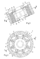
- a vane machine 1 has a stator 2 and a rotor 3, which are rotatably mounted to each other by means not shown.
- the rotor 3 has a plurality of wings 4, which are each radially displaceable in a guide 5 in the rotor 3.
- the wings 4 abut against an inner periphery 6 of the stator.
- a side wall 7 is arranged.
- openings 8, 9 may be provided, which can be used for the supply or for the discharge of water.
- Fig. 1 only one side wall 7 is shown.
- On the axially opposite end side of the stator 2 also has a side wall, which, however, is not shown. In this other side wall you can omit the openings 8, 9 under certain circumstances.
- the openings 8, 9 extend radially outward not quite to the stator 2. Rather, radially outward webs 10, 11 are provided, on which the wings 4 can rest in the axial direction when the rotor rotates. Also in the region of the openings 9, 10 so the wings are supported radially inward and radially outward in the axial direction.
- a through hole 12 is provided, through which, for example, a shaft can be guided, with which the rotor 3 is rotatably mounted relative to the stator 2.
- the passage opening 12 widens to a cavity 13.
- the wings 4 enter with their radial inner sides 14 in the cavity 13 when they are pressed by the inner periphery 6 of the stator 2 radially inward.
- a cam 15 is arranged in each case.
- the cam 15 may be fixed to the side wall 7 or formed integrally with the side wall 7. It has a shape that corresponds to the inner circumference 6 of the stator, but in a reduced version, as will be explained in more detail below.
- the wings 4 each have a recess 16 at its two axial ends. In this recess 16, the cam 15 engages. Each recess 16 has an axial extent corresponding to the axial thickness of the cam 15. The wings 4 are about this axial extent axially over the rotor 3, so that it is possible to make the wings 4 and the cam 15 in the axial direction flush with each other.
- the recesses 16 may have an extent in the radial direction, which is greater than a maximum stroke of the wing.
- the cam 15 then covers the wings 4 over their entire radial stroke in the region of the recess 16.
- the inner circumference 6 of the stator is about twice the radial Extension of the wings 4 reduced. Added twice the radial extent of the recesses 16. With such a shaped cam 15 ensures that the wings 4 always rest on the inner circumference 6 of the stator 2 and there ensure adequate sealing.
- the wings 4 abut with their front side either on the side wall 7 or on the cam 4, so that even there is given a sufficient seal.
- a seal radially inward results from the interaction of the wings 4 with the guides 5.
- the vane machine 1 shown there has two cycles per revolution.
- the result is a minimum distance between the inner periphery 6 of the stator 2 and the rotor 3 at points of the rotor 3, which point upwards and downwards, and a maximum distance at points which point to the left and to the right. Since a "delivery stroke" can always be realized when the maximum distance to the minimum distance decreases, the result in Fig. 2 illustrated embodiments two cycles per revolution. This possibility is provided by the cam 15.
- FIGS Fig. 1 and 2 show the vane machine 1 in perspective view. Same parts are denoted by the same reference numerals as in FIGS Fig. 1 and 2 Mistake.
- the cam 15 is formed here as a separate element. However, it may also be formed integrally with the side wall 7.
- cam 15 If one forms the cam 15 as a separate element, then you can dimension their two faces or pressure application surfaces on the two end faces, which can be defined for example by seals, not shown, so that there is a force balance on the rotor in the axial direction. This allows you to minimize a game and accordingly keep a small leak.
- the wings 4 have a core of a steel and a coating of a plastic friction-co-operating with steel.
- the wings 4 are designed so that they can interact with low friction with the stator 2 and the guides 5 in the rotor 3. Also at their end faces, which bear against the side wall 7 formed of steel, results in a reduced friction.
- plastics it is possible to use, for example, materials from the group of high-strength thermoplastics based on polyaryl ether ketones, in particular polyether ether ketones, Polyamides, polyacetals, polyaryl ethers, polyethylene terephthalates, polyphenylene sulfides, polysulfones, polyethersulfones, polyetherimides, polyamideimides, polyacrylates, phenolic resins such as novolak resins or the like, which may be glass, graphite, polytetrafluoroethylene or plastic, especially in fibrous form, as fillers , When using such materials, water can also be used as hydraulic fluid.
- polyaryl ether ketones polyether ether ketones
- the cam 15 should be provided with a corresponding plastic, at least in the area where the rotor 3 rests with its front side.
- the recesses 6 are expediently milled out of the wings 4 after the plastic has been applied , This results in the contact surface 17, an area which is at least partially formed of a steel and then rests against the plastic of the cam 15. Due to the rounded shape of the contact surface 17 can also be achieved that a contact between the plastic of the wing 4 and the plastic of the cam 15 can be practically avoided.
- the wing 4 then also has an end face 18, which is formed by the recess 6, which also consists essentially of the steel of the core of the wing 4 exists. This surface 18 then abuts axially on the cam 15, so that a pairing plastic - plastic is avoided and a mating steel - plastic is achieved here.
Landscapes
- Engineering & Computer Science (AREA)
- Mechanical Engineering (AREA)
- General Engineering & Computer Science (AREA)
- Rotary Pumps (AREA)
Abstract
Description
- Die Erfindung betrifft eine hydraulische Flügelzellenmaschine mit einem Stator und einem Rotor, der mehrere Flügel aufweist, die jeweils in einer Führung im Rotor radial verlagerbar sind, an einem Innenumfang des Stators anliegen und mit dem Rotor, dem Stator und je einer Seitenwand an jedem axialen Ende des Rotors Arbeitskammern begrenzen, deren Volumina sich bei einer Drehung des Rotors gegenüber dem Stator ändern.
- Eine derartige Flügelzellenmaschine ist aus
US 6 684 847 B1 bekannt. Die Flügel sind an beiden axialen Enden mit Vorsprüngen versehen, die jeweils in Nuten geführt sind, die im Stator vorgesehen sind. Der Verlauf der Nuten bestimmt die Bewegung der Flügel. - Eine derartige Flügelzellenmaschine kann beispielsweise als Verstärkungspumpe in einer Umkehrosmose-Anlage verwendet werden und wirkt dann als wasserhydraulische Maschine. In einer bislang verwendeten Ausgestaltung ist der Rotor exzentrisch zum Innenumfang des Stators gelagert. Ein Punkt an der Oberfläche des Rotors nähert sich dann bei einer Umdrehung einmal dem Innenumfang an, bis ein minimaler Abstand erreicht ist, und bewegt sich dann vom Innenumfang wieder weg, bis ein maximaler Abstand erreicht ist. Wenn die Flügelzellenmaschine als Pumpe verwendet wird, dann ist im Bereich des minimalen Abstandes eine Auslassöffnung für die jeweilige Arbeitskammer vorgesehen, aus der dann Wasser unter einem höheren Druck ausgegeben werden kann. Wenn die Flügelzellenmaschine als Motor verwendet wird, dann befindet sich in diesem Bereich ein Speise- oder Zuführanschluss, an dem Wasser unter Druck eingespeist werden kann.
- Bei einer derartigen Flügelzellenmaschine hat man bisher immer eine geradzahlige Anzahl von Flügeln verwendet und zwischen Flügeln, die einander diametral gegenüber liegen, einen Abstandshalter eingebaut, so dass zwei diametral einander gegenüber liegende Flügel immer genau einen Durchmesser abgebildet haben. Allerdings ist eine derartige Lösung nur bei Maschinen möglich, bei denen der Innenumfang des Stators eine Zylinderform aufweist.
- Der Erfindung liegt die Aufgabe zugrunde, eine gewisse Freiheit bei der Gestaltung des Innenumfangs zu haben. Diese Aufgabe wird bei einer hydraulischen Flügelzellenmaschine der eingangs genannten Art dadurch gelöst, dass jeder Flügel an seiner radialen Innenseite eine Anlagefläche aufweist, die radial außen an einer Kurvenscheibe anliegt.
- Bei einer derartigen Ausgestaltung ist man nicht länger darauf angewiesen, dass der Innenumfang für jede Winkelstellung des Rotors den gleichen Durchmesser aufweist. Vielmehr kann man hier wechselnde Durchmesser verwenden. Die Bewegung eines Flügels muss nicht mehr mit der Bewegung eines diametral gegenüber liegenden Flügels korrelieren. Dementsprechend kann man auch eine ungerade Anzahl von Flügeln verwenden. Die Verwendung einer Kurvenscheibe, an deren Außenumfang die Anlageflächen der Flügel anliegen, erlaubt es, die Flügel mit einer relativ großen Freiheit zu führen. Die Flügel werden durch die Kurvenscheibe radial nach außen gedrückt. Die Bewegung radial nach innen kann durch den Innenumfang des Stators bewirkt werden. Eine derartige Maschine kann auch mit Wasser als Hydraulikflüssigkeit betrieben werden und bildet dann eine wasserhydraulische Flügelzellenmaschine.
- Vorzugsweise ist die Anlagefläche an mindestens einem axialen Ende der Flügel ausgebildet. Damit kann man die Kurvenscheibe an einer axialen Stirnseite des Rotors anordnen, so dass der Aufbau des Rotors durch die Verwendung der Kurvenscheibe nicht gestört oder beeinträchtigt wird.
- Vorzugsweise ist die Anlagefläche in einer Ausnehmung am axialen Ende des Flügels ausgebildet. In diese Ausnehmung greift die Kurvenscheibe ein. Damit ist es möglich, dass die Kurvenscheibe die Flügel in radialer Richtung etwas überdeckt.
- Hierbei ist es bevorzugt, dass die Flügel axial über den Rotor überstehen. Man kann die Kurvenscheibe dann teilweise oder sogar vollständig axial außerhalb des Rotors anordnen, was den Vorteil hat, dass sich die Kurvenscheibe und der Rotor gegenseitig nicht stören.
- Vorzugsweise weist die Ausnehmung eine radiale Erstreckung auf, die größer als ein maximaler Hub des Flügels ist. Die Kurvenscheibe deckt also die Flügel im Bereich der Ausnehmung über den gesamten Hub ab. Die Kurvenscheibe dient also mit zur axialen Abdichtung der Flügel, so dass eine Leckage vermieden oder zumindest klein gehalten werden kann.
- Bevorzugterweise weist die Ausnehmung eine axiale Erstreckung auf, die einer axialen Dicke der Kurvenscheibe entspricht. In diesem Fall kann man dafür sorgen, dass die Flügel außerhalb der Ausnehmung mit ihrem axialen Ende an der Seitenwand und innerhalb der Ausnehmung mit ihrem axialen Ende an der Kurvenscheibe anliegen. Damit ergibt sich über die gesamte Höhe der Flügel in jeder Winkelstellung des Rotors gegenüber den stehenden Teilen eine Dichtfläche, die sich über die gesamte radiale Länge der axialen Enden der Flügel erstreckt. Damit lässt sich eine relativ gute Dichtigkeit sicherstellen.
- Vorzugsweise entspricht die Kurvenscheibe dem Innenumfang des Stators vermindert um das Doppelte der radialen Erstreckung der Flügel zuzüglich dem Doppelten der radialen Erstreckung der Ausnehmung. Dies ist eine relativ einfache Bemessungsvorschrift. Man kann die Kurvenscheibe sozusagen als verkleinerte Kopie des Innenumfangs des Stators ausbilden.
- Vorzugsweise ist die Anlagefläche gerundet. Damit hält man Reibung zwischen dem Flügel und der Kurvenscheibe klein. Es lässt sich praktisch nicht vermeiden, dass der Flügel in der Führung kippt. Auch wenn dieses Kippen sehr klein gehalten werden kann, könnten sich durch dieses Kippen Probleme einstellen. Derartige Probleme werden durch das Abrunden der Anlagefläche zuverlässig vermieden.
- In einer bevorzugten Ausgestaltung ist der Rotor zentrisch relativ zum Stator gelagert und ein Verlauf eines radialen Abstands zwischen dem Stator und dem Rotor weist in Umfangsrichtung mindestens zwei Maxima und zwei Minima auf. Mit einer derartigen Ausgestaltung erreicht man mindestens zwei Arbeitsspiele der Maschine pro Umdrehung des Rotors. Man ist nicht mehr darauf angewiesen, den Rotor exzentrisch zum Stator zu lagern. Diese Ausgestaltung würde nur ein Arbeitsspiel erlauben.
- Vorzugsweise weist der Rotor eine Durchgangsöffnung, die sich axial innen zu einem Hohlraum erweitert, zur Aufnahme einer Achse auf. Der Hohlraum dient dazu, die Masse des Rotors zu vermindern.
- Hierbei ist bevorzugt, dass die Flügel mit ihrer radialen Innenseite bei einem Einwärtshub in den Hohlraum eintreten. Dann wird der Hohlraum zwar mit Wasser gefüllt, wenn die Maschine betrieben wird. Dies ist aber unkritisch, weil sich der Druck des Wassers im Hohlraum auf einen Mittelwert einstellen kann.
- Bevorzugterweise weisen die Flügel einen Kern aus einem Stahl und einem Überzug aus einem mit Stahl reibungsarm zusammenwirkenden Kunststoff auf. In diesem Fall kann man den Rotor und den Stator aus Stahl bilden. Da Wasser keine schmierenden Eigenschaften besitzt, wird die Reibungsverminderung, die bei einer ölhydraulischen Maschine durch ein Hydrauliköl bewirkt wird, in diesem Fall von dem reibungsvermindernden Kunststoff bewirkt. Als Kunststoff für den Überzug kommen insbesondere Werkstoffe aus der Gruppe der hochfesten thermoplastischen Kunststoffe auf der Basis von Polyaryletherketonen, insbesondere Polyetheretherketonen, Polyamiden, Polyacetalen, Polyarylether, Polyethylenterephtalaten, Polyphenylensulfiden, Polysulfonen, Polyethersulfonen, Polyetherimiden, Polyamidimiden, Polyacrylaten, Phenol-Harzen, wie Novolack-Harzen, oder Ähnliches in Betracht, wobei als Füllstoffe Glas, Graphit, Polytetrafluorethylen oder Kunststoff, insbesondere in Faserform, verwendet werden können. Bei Verwendung derartiger Materialien lässt sich auch Wasser als Hydraulikflüssigkeit verwenden.
- In diesem Fall ist bevorzugt, dass jeder Flügel im Bereich der Führung eine aus dem mit Stahl reibungsarm zusammenwirkenden Kunststoff gebildete Oberfläche aufweist und die Anlagefläche zumindest teilweise aus einem Stahl gebildet ist, wobei die Kurvenscheibe zumindest in einem Bereich, an dem die Anlagefläche anliegt, eine aus einem mit Stahl reibungsarm zusammenwirkenden Kunststoff gebildete Oberfläche aufweist. In diesem Fall kann man erreichen, dass zwischen bewegten Teilen immer eine Paarung Kunststoff - Stahl vorliegt. Man kann also vermeiden, dass sich über größere Kontaktbereiche eine Paarung Kunststoff - Kunststoff ergibt, was jedenfalls im Hinblick auf die Reibungsverminderung und den Verschleiß nachteilig wäre.
- Vorzugsweise ist die Kurvenscheibe einstückig mit der Seitenplatte ausgebildet. Sie kann beispielsweise durch einen Vorsprung auf der Seitenplatte gebildet sein.
- In einer bevorzugten Ausgestaltung ist vorgesehen, dass mindestens eine Seitenwand mindestens eine Öffnung aufweist, die radial außen von einem Steg begrenzt ist, an dem die Flügel anliegen. Auch im Bereich der Öffnung wird also erreicht, dass die Flügel in Axialrichtung radial innen und radial außen abgestützt sind. Ein Kippen der Flügel in eine Richtung parallel zur Rotationsachse kann damit zuverlässig vermieden werden.
- Die Erfindung wird im Folgenden anhand eines bevorzugten Ausführungsbeispiels in Verbindung mit einer Zeichnung beschrieben. Hierin zeigen:
- Fig. 1
- eine Schnittdarstellung I-I einer Flügelzellenmaschine nach
Fig. 2 , - Fig. 2
- eine Schnittdarstellung I-I der Flügelzellenmaschine nach
Fig. 1 , - Fig. 3
- eine perspektivische Darstellung der Flügelzellenmaschine ohne Seitenwand und
- Fig. 4
- die Darstellung nach
Fig. 3 ohne Kurvenscheibe. - Eine Flügelzellenmaschine 1 weist einen Stator 2 und einen Rotor 3 auf, die mit nicht näher dargestellten Mitteln drehbar zueinander gelagert sind. Der Rotor 3 weist mehrere Flügel 4 auf, die jeweils in einer Führung 5 im Rotor 3 radial verlagerbar sind. Die Flügel 4 liegen an einem Innenumfang 6 des Stators an. An jedem axialen Ende des Stators ist eine Seitenwand 7 angeordnet. In der Seitenwand 7 können Öffnungen 8, 9 vorgesehen sein, die zur Zufuhr bzw. zur Abfuhr von Wasser verwendet werden können. In
Fig. 1 ist nur eine Seitenwand 7 dargestellt. Auf der axial gegenüber liegenden Stirnseite weist der Stator 2 ebenfalls eine Seitenwand auf, die allerdings nicht dargestellt ist. In dieser anderen Seitenwand kann man die Öffnungen 8, 9 unter Umständen weglassen. - Die Öffnungen 8, 9 erstrecken sich radial nach außen nicht ganz bis zum Stator 2. Vielmehr sind radial außen Stege 10, 11 vorgesehen, an denen die Flügel 4 in Axialrichtung anliegen können, wenn sich der Rotor dreht. Auch im Bereich der Öffnungen 9, 10 sind also die Flügel radial innen und radial außen in Axialrichtung abgestützt.
- Im Rotor 3 ist eine Durchgangsöffnung 12 vorgesehen, durch die beispielsweise eine Welle geführt werden kann, mit der der Rotor 3 drehbar gegenüber dem Stator 2 gelagert ist. Axial in der Mitte erweitert sich die Durchgangsöffnung 12 zu einem Hohlraum 13. Wie insbesondere aus
Fig. 2 zu erkennen ist, treten die Flügel 4 mit ihren radialen Innenseiten 14 in den Hohlraum 13 ein, wenn sie durch den Innenumfang 6 des Stators 2 radial nach innen gedrückt werden. - An beiden axialen Stirnseiten des Rotors 3 ist jeweils eine Kurvenscheibe 15 angeordnet. Die Kurvenscheibe 15 kann an der Seitenwand 7 befestigt sein oder einstückig mit der Seitenwand 7 ausgebildet sein. Sie weist eine Form auf, die dem Innenumfang 6 des Stators entspricht, allerdings in einer verkleinerten Fassung, wie weiter unten näher erläutert wird.
- Die Flügel 4 weisen an ihren beiden axialen Enden jeweils eine Ausnehmung 16 auf. In diese Ausnehmung 16 greift die Kurvenscheibe 15 ein. Jede Ausnehmung 16 weist eine axiale Erstreckung auf, die der axialen Dicke der Kurvenscheibe 15 entspricht. Die Flügel 4 stehen um diese axiale Erstreckung axial über den Rotor 3 über, so dass es möglich ist, die Flügel 4 und die Kurvenscheibe 15 in axialer Richtung bündig miteinander abschließen zu lassen.
- Die Ausnehmungen 16 können eine Erstreckung in radialer Richtung aufweisen, die größer ist als ein maximaler Hub des Flügels. Die Kurvenscheibe 15 deckt dann die Flügel 4 über ihren gesamten radialen Hub im Bereich der Ausnehmung 16 ab.
- Dementsprechend kann man eine relativ einfache Vorschrift erstellen, wie die Kurvenscheibe zu gestalten ist. Der Innenumfang 6 des Stators wird um das Doppelte der radialen Erstreckung der Flügel 4 vermindert. Hinzugefügt wird das Doppelte der radialen Erstreckung der Ausnehmungen 16. Mit einer derartig gestalteten Kurvenscheibe 15 wird sichergestellt, dass die Flügel 4 immer am Innenumfang 6 des Stators 2 anliegen und dort für eine ausreichende Abdichtung sorgen.
- An den axialen Enden liegen die Flügel 4 mit ihrer Stirnseite entweder an der Seitenwand 7 oder an der Kurvenscheibe 4 an, so dass auch dort eine ausreichende Abdichtung gegeben ist. Eine Abdichtung radial nach innen ergibt sich durch das Zusammenwirken der Flügel 4 mit den Führungen 5. In allen Bereichen können natürlich kleine Leckagen auftreten, weil hier bewegte Teile gegeneinander abgedichtet werden müssen. Die Leckagen können jedoch relativ klein gehalten werden.
- Wie in
Fig. 2 zu erkennen ist, weist die dort dargestellte Flügelzellenmaschine 1 zwei Arbeitsspiele pro Umdrehung auf. Bezogen auf die Darstellung derFig. 2 ergibt sich ein minimaler Abstand zwischen dem Innenumfang 6 des Stators 2 und dem Rotor 3 an Punkten des Rotors 3, die nach oben und nach unten weisen, und ein maximaler Abstand an Punkten, die nach links und nach rechts weisen. Da sich ein "Förderhub" immer dann realisieren lässt, wenn sich der maximale Abstand zum minimalen Abstand hin verkleinert, ergeben sich bei der inFig. 2 dargestellten Ausführungsformen zwei Arbeitsspiele pro Umdrehung. Diese Möglichkeit wird durch die Kurvenscheibe 15 zur Verfügung gestellt. - Die
Fig. 3 und4 zeigen die Flügelzellenmaschine 1 in perspektivischer Darstellung. Gleiche Teile sind mit den gleichen Bezugszeichen wie in denFig. 1 und 2 versehen. - Die
Fig. 3 und4 lassen etwas deutlicher erkennen, dass die radialen Innenseiten der Flügel 4 im Bereich der Ausnehmungen 16, die Anlageflächen 17 der Flügel 4 an der Kurvenscheibe 15 bilden, gerundet sind. - Die Kurvenscheibe 15 ist hier als getrenntes Element ausgebildet. Sie kann jedoch auch einstückig mit der Seitenwand 7 ausgebildet sein.
- Wenn man die Kurvenscheibe 15 als getrenntes Element ausbildet, dann kann man ihre beiden Stirnseiten bzw. Druckangriffsflächen an den beiden Stirnseiten, die beispielsweise durch nicht dargestellte Dichtungen definiert werden können, so dimensionieren, dass sich ein Kraftgleichgewicht über den Rotor in axialer Richtung ergibt. Dadurch kann man ein Spiel minimieren und entsprechend auch eine Leckage klein halten.
- Die Flügel 4 weisen einen Kern aus einem Stahl und einen Überzug aus einem mit Stahl reibungsarm zusammenwirkenden Kunststoff auf. Damit sind die Flügel 4 so ausgestaltet, dass sie reibungsarm mit dem Stator 2 und den Führungen 5 im Rotor 3 zusammenwirken können. Auch an ihren Stirnseiten, die an der aus Stahl gebildeten Seitenwand 7 anliegen, ergibt sich eine verringerte Reibung. Als Kunststoffe kann man beispielsweise Werkstoffe aus der Gruppe der hochfesten thermoplastischen Kunststoffe auf der Basis von Polyaryletherketonen verwenden, insbesondere Polyetheretherketonen, Polyamiden, Polyacetalen, Polyarylether, Polyethylenterephtalaten, Polyphenylensulfiden, Polysulfonen, Polyethersulfonen, Polyetherimiden, Polyamidimiden, Polyacrylaten, Phenol-Harzen, wie Novolack-Harzen, oder Ähnliches, wobei als Füllstoffe Glas, Graphit, Polytetrafluorethylen oder Kunststoff, insbesondere in Faserform, verwendet werden können. Bei Verwendung derartiger Materialien lässt sich auch Wasser als Hydraulikflüssigkeit verwenden.
- Zweckmäßigerweise sollte auch die Kurvenscheibe 15 mit einem entsprechenden Kunststoff versehen sein, jedenfalls in dem Bereich, an dem der Rotor 3 mit seiner Stirnseite anliegt.
- Um nun zu vermeiden, dass die Flügel 4 dann mit einem mit Kunststoff beschichteten Bereich an der Kurvenscheibe 15 dort anliegen, wo die Kurvenscheibe 15 ebenfalls mit Kunststoff beschichtet ist, sind die Ausnehmungen 6 zweckmäßigerweise aus den Flügeln 4 herausgefräst, nachdem der Kunststoff aufgetragen worden ist. Damit ergibt sich in der Anlagefläche 17 ein Bereich, der zumindest teilweise aus einem Stahl gebildet ist und der dann an dem Kunststoff der Kurvenscheibe 15 anliegt. Durch die gerundete Form der Anlagefläche 17 lässt sich auch erreichen, dass ein Kontakt zwischen dem Kunststoff des Flügels 4 und dem Kunststoff der Kurvenscheibe 15 praktisch vermieden werden kann.
- Der Flügel 4 weist dann auch eine stirnseitige Fläche 18 auf, die durch die Ausnehmung 6 gebildet ist, die ebenfalls im Wesentlichen aus dem Stahl des Kerns des Flügels 4 besteht. Diese Fläche 18 liegt dann axial an der Kurvenscheibe 15 an, so dass auch hier eine Paarung Kunststoff - Kunststoff vermieden wird und eine Paarung Stahl - Kunststoff erreicht wird.
Claims (14)
- Hydraulische Flügelzellenmaschine (1) mit einem Stator (2) und einem Rotor (3), der mehrere Flügel (4) aufweist, die jeweils in einer Führung (5) im Rotor (3) radial verlagerbar sind, an einem Innenumfang (6) des Stators (2) anliegen und mit dem Rotor (3), dem Stator (2) und je einer Seitenwand (7) an jedem axialen Ende des Rotors (3) Arbeitskammern begrenzen, deren Volumina sich bei einer Drehung des Rotors (3) gegenüber dem Stator (2) ändern, dadurch gekennzeichnet, dass jeder Flügel (4) an seiner radialen Innenseite eine Anlagefläche (17) aufweist, die radial außen an einer Kurvenscheibe (15) anliegt.
- Flügelzellenmaschine nach Anspruch 1, dadurch gekennzeichnet, dass die Anlagefläche (17) an mindestens einem axialen Ende der Flügel (4) ausgebildet ist.
- Flügelzellenmaschine nach Anspruch 2, dadurch gekennzeichnet, dass die Anlagefläche (17) in einer Ausnehmung (16) am axialen Ende des Flügels (4) ausgebildet ist.
- Flügelzellenmaschine nach Anspruch 3, dadurch gekennzeichnet, dass die Flügel (4) axial über den Rotor (3) überstehen.
- Flügelzellenmaschine nach Anspruch 3 oder 4,
dadurch gekennzeichnet, dass die Ausnehmung (16) eine radiale Erstreckung aufweist, die größer als ein maximaler Hub des Flügels (4) ist. - Flügelzellenmaschine nach einem der Ansprüche 3 bis 5, dadurch gekennzeichnet, dass die Ausnehmung (16) eine axiale Erstreckung aufweist, die einer axialen Dicke der Kurvenscheibe (15) entspricht.
- Flügelzellenmaschine nach einem der Ansprüche 5 oder 6, dadurch gekennzeichnet, dass die Kurvenscheibe (15) dem Innenumfang (6) des Stators (2) vermindert um das Doppelte der radialen Erstreckung der Flügel (4) zuzüglich dem Doppelten der radialen Erstreckung der Ausnehmung (16) entspricht.
- Flügelzellenmaschine nach einem der Ansprüche 1 bis 7, dadurch gekennzeichnet, dass die Anlagefläche (17) gerundet ist.
- Flügelzellenmaschine nach einem der Ansprüche 1 bis 8, dadurch gekennzeichnet, dass der Rotor (3) zentrisch relativ zum Stator (2) gelagert ist und ein Verlauf eines radialen Abstands zwischen dem Stator (2) und dem Rotor (3) in Umfangsrichtung mindestens zwei Maxima und zwei Minima aufweist.
- Flügelzellenmaschine nach einem der Ansprüche 1 bis 9, dadurch gekennzeichnet, dass der Rotor (3) eine Durchgangsöffnung (12) zur Aufnahme einer Achse aufweist, die sich axial innen zu einem Hohlraum (13) erweitert.
- Flügelzellenmaschine nach Anspruch 10, dadurch gekennzeichnet, dass die Flügel (4) mit ihrer radialen Innenseite (14) bei einem Einwärtshub in den Hohlraum (13) eintreten.
- Flügelzellenmaschine nach einem der Ansprüche 1 bis 11, dadurch gekennzeichnet, dass die Flügel (4) einen Kern aus einem Stahl und einen Überzug aus dem mit Stahl reibungsarm zusammenwirkenden Kunststoff aufweisen.
- Flügelzellenmaschine nach Anspruch 12, dadurch gekennzeichnet, dass jeder Flügel (4) im Bereich der Führung (5) eine aus einem mit Stahl reibungsarm zusammenwirkenden Kunststoff gebildete Oberfläche aufweist und die Anlagefläche (17) zumindest teilweise aus einem Stahl gebildet ist, wobei die Kurvenscheibe (15) zumindest in einem Bereich, an dem der Flügel (4) anliegt, eine aus einem mit Stahl reibungsarm zusammenwirkenden Kunststoff gebildete Oberfläche aufweist.
- Flügelzellenmaschine nach einem der Ansprüche 1 bis 13, dadurch gekennzeichnet, dass die Kurvenscheibe (15) einstückig mit der der Seitenwand (7) ausgebildet ist.
Priority Applications (4)
| Application Number | Priority Date | Filing Date | Title |
|---|---|---|---|
| EP14193256.6A EP3020917B1 (de) | 2014-11-14 | 2014-11-14 | Hydraulische Flügelzellenmaschine |
| ES14193256T ES2813957T3 (es) | 2014-11-14 | 2014-11-14 | Máquina hidráulica de aletas |
| CN201510683523.5A CN105604781B (zh) | 2014-11-14 | 2015-10-20 | 液压叶片式机器 |
| US14/930,720 US9945231B2 (en) | 2014-11-14 | 2015-11-03 | Hydraulic vane-type machine |
Applications Claiming Priority (1)
| Application Number | Priority Date | Filing Date | Title |
|---|---|---|---|
| EP14193256.6A EP3020917B1 (de) | 2014-11-14 | 2014-11-14 | Hydraulische Flügelzellenmaschine |
Publications (2)
| Publication Number | Publication Date |
|---|---|
| EP3020917A1 true EP3020917A1 (de) | 2016-05-18 |
| EP3020917B1 EP3020917B1 (de) | 2020-07-15 |
Family
ID=51904772
Family Applications (1)
| Application Number | Title | Priority Date | Filing Date |
|---|---|---|---|
| EP14193256.6A Active EP3020917B1 (de) | 2014-11-14 | 2014-11-14 | Hydraulische Flügelzellenmaschine |
Country Status (4)
| Country | Link |
|---|---|
| US (1) | US9945231B2 (de) |
| EP (1) | EP3020917B1 (de) |
| CN (1) | CN105604781B (de) |
| ES (1) | ES2813957T3 (de) |
Families Citing this family (2)
| Publication number | Priority date | Publication date | Assignee | Title |
|---|---|---|---|---|
| JP7037458B2 (ja) * | 2018-09-07 | 2022-03-16 | 日立Astemo株式会社 | ポンプ装置 |
| CN111550361B (zh) * | 2020-06-28 | 2022-03-18 | 河北中清永晟石油科技有限公司 | 新型容积式井下发电装置及包含其的新型油田注水系统 |
Citations (6)
| Publication number | Priority date | Publication date | Assignee | Title |
|---|---|---|---|---|
| FR1315068A (fr) * | 1961-11-09 | 1963-01-18 | Moteur à combustion interne à piston rotatif | |
| DE2316529A1 (de) * | 1973-04-03 | 1974-10-24 | Alfons Lugauer | Kraftmaschine, z.b. verbrennungsoder hydraulischer motor oder pumpe |
| US4454844A (en) * | 1980-03-03 | 1984-06-19 | Kinsey Lewis R | Four cycle rotary engine employing eccentrical mounted rotor |
| DE3524275A1 (de) * | 1985-07-06 | 1986-04-17 | Daniel 7750 Konstanz Becker | Drehkolbenartige umlauf-kolbenmaschine |
| DE10109572A1 (de) * | 2001-02-22 | 2001-10-31 | Andreas Ohl | Flügel-Kolben Motor |
| US6684847B1 (en) | 2002-07-10 | 2004-02-03 | Osama Al-Hawaj | Radial vane rotary device |
Family Cites Families (5)
| Publication number | Priority date | Publication date | Assignee | Title |
|---|---|---|---|---|
| EP0247001A3 (de) * | 1986-05-22 | 1988-09-28 | Hans Dr. Wälchli | Flügelzellenpumpe zum Fördern von pastösen Lebensmitteln, insbesondere von Wurstbrät |
| BRPI0618898B1 (pt) * | 2005-11-23 | 2019-01-15 | Global Power Tech Inc | motor de combustão interna |
| DE102011116869B4 (de) * | 2011-10-25 | 2015-07-02 | Danfoss A/S | Flügelzellenmaschine |
| CN102536801B (zh) * | 2011-12-12 | 2015-04-22 | 马燕翔 | 无定子磨损的滑片泵 |
| JP5897945B2 (ja) * | 2012-03-22 | 2016-04-06 | 日立オートモティブシステムズ株式会社 | ベーンポンプ |
-
2014
- 2014-11-14 ES ES14193256T patent/ES2813957T3/es active Active
- 2014-11-14 EP EP14193256.6A patent/EP3020917B1/de active Active
-
2015
- 2015-10-20 CN CN201510683523.5A patent/CN105604781B/zh active Active
- 2015-11-03 US US14/930,720 patent/US9945231B2/en active Active
Patent Citations (6)
| Publication number | Priority date | Publication date | Assignee | Title |
|---|---|---|---|---|
| FR1315068A (fr) * | 1961-11-09 | 1963-01-18 | Moteur à combustion interne à piston rotatif | |
| DE2316529A1 (de) * | 1973-04-03 | 1974-10-24 | Alfons Lugauer | Kraftmaschine, z.b. verbrennungsoder hydraulischer motor oder pumpe |
| US4454844A (en) * | 1980-03-03 | 1984-06-19 | Kinsey Lewis R | Four cycle rotary engine employing eccentrical mounted rotor |
| DE3524275A1 (de) * | 1985-07-06 | 1986-04-17 | Daniel 7750 Konstanz Becker | Drehkolbenartige umlauf-kolbenmaschine |
| DE10109572A1 (de) * | 2001-02-22 | 2001-10-31 | Andreas Ohl | Flügel-Kolben Motor |
| US6684847B1 (en) | 2002-07-10 | 2004-02-03 | Osama Al-Hawaj | Radial vane rotary device |
Also Published As
| Publication number | Publication date |
|---|---|
| US9945231B2 (en) | 2018-04-17 |
| US20160138398A1 (en) | 2016-05-19 |
| CN105604781B (zh) | 2018-11-27 |
| EP3020917B1 (de) | 2020-07-15 |
| ES2813957T3 (es) | 2021-03-25 |
| CN105604781A (zh) | 2016-05-25 |
Similar Documents
| Publication | Publication Date | Title |
|---|---|---|
| DE2443720C3 (de) | Drehkolbenpumpe für Flüssigkeiten | |
| EP2359005B1 (de) | Flügelzellenpumpe | |
| EP2961988B1 (de) | Aus wenigstens zwei teilen gebildete schraubenspindelpumpe | |
| EP2337928A2 (de) | Pumpe, insbesondere flügelzellenpumpe | |
| DE102006057364B4 (de) | Wasserhydraulische Maschine | |
| DE102011116869B4 (de) | Flügelzellenmaschine | |
| WO2016173798A1 (de) | Pumpenvorrichtung | |
| DE102011116858B4 (de) | Flügelzellenmaschine | |
| EP0659237B1 (de) | Flügelzellenmaschine | |
| EP1861623B1 (de) | Flügelzellenmaschine, insbesondere flügelzellenpumpe | |
| WO2008148472A1 (de) | Flügelzellenpumpe | |
| DE1653801A1 (de) | Kapselpumpe | |
| WO2016173800A1 (de) | Pumpenvorrichtung | |
| EP2510192B1 (de) | Hydrostatische radialkolbenmaschine | |
| EP3020917B1 (de) | Hydraulische Flügelzellenmaschine | |
| DE102005048602A1 (de) | Flügelzellenmaschine, insbesondere Flügelzellenpumpe | |
| DE102018100614B4 (de) | Strömungsoptimierte Flügelzellenpumpe | |
| EP3430263B1 (de) | Membranpumpe | |
| DE1812251B2 (de) | Flügelzellenpumpe | |
| DE1728268A1 (de) | Fluegelzellenpumpe oder- motor | |
| DE2015610A1 (de) | Mit einer Steuervorrichtung versehene Pumpe | |
| WO2014191175A1 (de) | Verdrängerpumpe, insbesondere flügelzellenpumpe | |
| DE102019127389A1 (de) | Flügelzellenpumpe | |
| WO2009019095A1 (de) | Flügelzellenpumpe mit verringerter flächenpressung der flügel | |
| DE102013224660A1 (de) | Flügelzellenmaschine mit definiertem Druck in den Hinterflügelräumen |
Legal Events
| Date | Code | Title | Description |
|---|---|---|---|
| PUAI | Public reference made under article 153(3) epc to a published international application that has entered the european phase |
Free format text: ORIGINAL CODE: 0009012 |
|
| AK | Designated contracting states |
Kind code of ref document: A1 Designated state(s): AL AT BE BG CH CY CZ DE DK EE ES FI FR GB GR HR HU IE IS IT LI LT LU LV MC MK MT NL NO PL PT RO RS SE SI SK SM TR |
|
| AX | Request for extension of the european patent |
Extension state: BA ME |
|
| STAA | Information on the status of an ep patent application or granted ep patent |
Free format text: STATUS: REQUEST FOR EXAMINATION WAS MADE |
|
| 17P | Request for examination filed |
Effective date: 20161116 |
|
| RBV | Designated contracting states (corrected) |
Designated state(s): AL AT BE BG CH CY CZ DE DK EE ES FI FR GB GR HR HU IE IS IT LI LT LU LV MC MK MT NL NO PL PT RO RS SE SI SK SM TR |
|
| STAA | Information on the status of an ep patent application or granted ep patent |
Free format text: STATUS: EXAMINATION IS IN PROGRESS |
|
| 17Q | First examination report despatched |
Effective date: 20181116 |
|
| GRAJ | Information related to disapproval of communication of intention to grant by the applicant or resumption of examination proceedings by the epo deleted |
Free format text: ORIGINAL CODE: EPIDOSDIGR1 |
|
| STAA | Information on the status of an ep patent application or granted ep patent |
Free format text: STATUS: GRANT OF PATENT IS INTENDED |
|
| GRAP | Despatch of communication of intention to grant a patent |
Free format text: ORIGINAL CODE: EPIDOSNIGR1 |
|
| INTG | Intention to grant announced |
Effective date: 20200227 |
|
| RIN1 | Information on inventor provided before grant (corrected) |
Inventor name: HAUGAARD, ERIK Inventor name: PETERSEN, HANS CHRISTIAN |
|
| GRAJ | Information related to disapproval of communication of intention to grant by the applicant or resumption of examination proceedings by the epo deleted |
Free format text: ORIGINAL CODE: EPIDOSDIGR1 |
|
| STAA | Information on the status of an ep patent application or granted ep patent |
Free format text: STATUS: EXAMINATION IS IN PROGRESS |
|
| GRAR | Information related to intention to grant a patent recorded |
Free format text: ORIGINAL CODE: EPIDOSNIGR71 |
|
| GRAS | Grant fee paid |
Free format text: ORIGINAL CODE: EPIDOSNIGR3 |
|
| STAA | Information on the status of an ep patent application or granted ep patent |
Free format text: STATUS: GRANT OF PATENT IS INTENDED |
|
| GRAA | (expected) grant |
Free format text: ORIGINAL CODE: 0009210 |
|
| STAA | Information on the status of an ep patent application or granted ep patent |
Free format text: STATUS: THE PATENT HAS BEEN GRANTED |
|
| INTC | Intention to grant announced (deleted) | ||
| AK | Designated contracting states |
Kind code of ref document: B1 Designated state(s): AL AT BE BG CH CY CZ DE DK EE ES FI FR GB GR HR HU IE IS IT LI LT LU LV MC MK MT NL NO PL PT RO RS SE SI SK SM TR |
|
| INTG | Intention to grant announced |
Effective date: 20200605 |
|
| REG | Reference to a national code |
Ref country code: CH Ref legal event code: EP Ref country code: GB Ref legal event code: FG4D Free format text: NOT ENGLISH |
|
| REG | Reference to a national code |
Ref country code: IE Ref legal event code: FG4D Free format text: LANGUAGE OF EP DOCUMENT: GERMAN |
|
| REG | Reference to a national code |
Ref country code: DE Ref legal event code: R096 Ref document number: 502014014450 Country of ref document: DE |
|
| REG | Reference to a national code |
Ref country code: AT Ref legal event code: REF Ref document number: 1291248 Country of ref document: AT Kind code of ref document: T Effective date: 20200815 |
|
| REG | Reference to a national code |
Ref country code: LT Ref legal event code: MG4D |
|
| REG | Reference to a national code |
Ref country code: NL Ref legal event code: MP Effective date: 20200715 |
|
| PG25 | Lapsed in a contracting state [announced via postgrant information from national office to epo] |
Ref country code: FI Free format text: LAPSE BECAUSE OF FAILURE TO SUBMIT A TRANSLATION OF THE DESCRIPTION OR TO PAY THE FEE WITHIN THE PRESCRIBED TIME-LIMIT Effective date: 20200715 Ref country code: LT Free format text: LAPSE BECAUSE OF FAILURE TO SUBMIT A TRANSLATION OF THE DESCRIPTION OR TO PAY THE FEE WITHIN THE PRESCRIBED TIME-LIMIT Effective date: 20200715 Ref country code: PT Free format text: LAPSE BECAUSE OF FAILURE TO SUBMIT A TRANSLATION OF THE DESCRIPTION OR TO PAY THE FEE WITHIN THE PRESCRIBED TIME-LIMIT Effective date: 20201116 Ref country code: HR Free format text: LAPSE BECAUSE OF FAILURE TO SUBMIT A TRANSLATION OF THE DESCRIPTION OR TO PAY THE FEE WITHIN THE PRESCRIBED TIME-LIMIT Effective date: 20200715 Ref country code: SE Free format text: LAPSE BECAUSE OF FAILURE TO SUBMIT A TRANSLATION OF THE DESCRIPTION OR TO PAY THE FEE WITHIN THE PRESCRIBED TIME-LIMIT Effective date: 20200715 Ref country code: BG Free format text: LAPSE BECAUSE OF FAILURE TO SUBMIT A TRANSLATION OF THE DESCRIPTION OR TO PAY THE FEE WITHIN THE PRESCRIBED TIME-LIMIT Effective date: 20201015 Ref country code: GR Free format text: LAPSE BECAUSE OF FAILURE TO SUBMIT A TRANSLATION OF THE DESCRIPTION OR TO PAY THE FEE WITHIN THE PRESCRIBED TIME-LIMIT Effective date: 20201016 Ref country code: NO Free format text: LAPSE BECAUSE OF FAILURE TO SUBMIT A TRANSLATION OF THE DESCRIPTION OR TO PAY THE FEE WITHIN THE PRESCRIBED TIME-LIMIT Effective date: 20201015 |
|
| PG25 | Lapsed in a contracting state [announced via postgrant information from national office to epo] |
Ref country code: PL Free format text: LAPSE BECAUSE OF FAILURE TO SUBMIT A TRANSLATION OF THE DESCRIPTION OR TO PAY THE FEE WITHIN THE PRESCRIBED TIME-LIMIT Effective date: 20200715 Ref country code: RS Free format text: LAPSE BECAUSE OF FAILURE TO SUBMIT A TRANSLATION OF THE DESCRIPTION OR TO PAY THE FEE WITHIN THE PRESCRIBED TIME-LIMIT Effective date: 20200715 Ref country code: LV Free format text: LAPSE BECAUSE OF FAILURE TO SUBMIT A TRANSLATION OF THE DESCRIPTION OR TO PAY THE FEE WITHIN THE PRESCRIBED TIME-LIMIT Effective date: 20200715 Ref country code: IS Free format text: LAPSE BECAUSE OF FAILURE TO SUBMIT A TRANSLATION OF THE DESCRIPTION OR TO PAY THE FEE WITHIN THE PRESCRIBED TIME-LIMIT Effective date: 20201115 |
|
| REG | Reference to a national code |
Ref country code: ES Ref legal event code: FG2A Ref document number: 2813957 Country of ref document: ES Kind code of ref document: T3 Effective date: 20210325 |
|
| PG25 | Lapsed in a contracting state [announced via postgrant information from national office to epo] |
Ref country code: NL Free format text: LAPSE BECAUSE OF FAILURE TO SUBMIT A TRANSLATION OF THE DESCRIPTION OR TO PAY THE FEE WITHIN THE PRESCRIBED TIME-LIMIT Effective date: 20200715 |
|
| REG | Reference to a national code |
Ref country code: DE Ref legal event code: R097 Ref document number: 502014014450 Country of ref document: DE |
|
| PG25 | Lapsed in a contracting state [announced via postgrant information from national office to epo] |
Ref country code: RO Free format text: LAPSE BECAUSE OF FAILURE TO SUBMIT A TRANSLATION OF THE DESCRIPTION OR TO PAY THE FEE WITHIN THE PRESCRIBED TIME-LIMIT Effective date: 20200715 Ref country code: SM Free format text: LAPSE BECAUSE OF FAILURE TO SUBMIT A TRANSLATION OF THE DESCRIPTION OR TO PAY THE FEE WITHIN THE PRESCRIBED TIME-LIMIT Effective date: 20200715 Ref country code: IT Free format text: LAPSE BECAUSE OF FAILURE TO SUBMIT A TRANSLATION OF THE DESCRIPTION OR TO PAY THE FEE WITHIN THE PRESCRIBED TIME-LIMIT Effective date: 20200715 Ref country code: DK Free format text: LAPSE BECAUSE OF FAILURE TO SUBMIT A TRANSLATION OF THE DESCRIPTION OR TO PAY THE FEE WITHIN THE PRESCRIBED TIME-LIMIT Effective date: 20200715 Ref country code: EE Free format text: LAPSE BECAUSE OF FAILURE TO SUBMIT A TRANSLATION OF THE DESCRIPTION OR TO PAY THE FEE WITHIN THE PRESCRIBED TIME-LIMIT Effective date: 20200715 Ref country code: CZ Free format text: LAPSE BECAUSE OF FAILURE TO SUBMIT A TRANSLATION OF THE DESCRIPTION OR TO PAY THE FEE WITHIN THE PRESCRIBED TIME-LIMIT Effective date: 20200715 |
|
| PLBE | No opposition filed within time limit |
Free format text: ORIGINAL CODE: 0009261 |
|
| STAA | Information on the status of an ep patent application or granted ep patent |
Free format text: STATUS: NO OPPOSITION FILED WITHIN TIME LIMIT |
|
| PG25 | Lapsed in a contracting state [announced via postgrant information from national office to epo] |
Ref country code: AL Free format text: LAPSE BECAUSE OF FAILURE TO SUBMIT A TRANSLATION OF THE DESCRIPTION OR TO PAY THE FEE WITHIN THE PRESCRIBED TIME-LIMIT Effective date: 20200715 |
|
| 26N | No opposition filed |
Effective date: 20210416 |
|
| PG25 | Lapsed in a contracting state [announced via postgrant information from national office to epo] |
Ref country code: MC Free format text: LAPSE BECAUSE OF FAILURE TO SUBMIT A TRANSLATION OF THE DESCRIPTION OR TO PAY THE FEE WITHIN THE PRESCRIBED TIME-LIMIT Effective date: 20200715 Ref country code: SK Free format text: LAPSE BECAUSE OF FAILURE TO SUBMIT A TRANSLATION OF THE DESCRIPTION OR TO PAY THE FEE WITHIN THE PRESCRIBED TIME-LIMIT Effective date: 20200715 |
|
| REG | Reference to a national code |
Ref country code: CH Ref legal event code: PL |
|
| PG25 | Lapsed in a contracting state [announced via postgrant information from national office to epo] |
Ref country code: LU Free format text: LAPSE BECAUSE OF NON-PAYMENT OF DUE FEES Effective date: 20201114 |
|
| REG | Reference to a national code |
Ref country code: BE Ref legal event code: MM Effective date: 20201130 |
|
| PG25 | Lapsed in a contracting state [announced via postgrant information from national office to epo] |
Ref country code: LI Free format text: LAPSE BECAUSE OF NON-PAYMENT OF DUE FEES Effective date: 20201130 Ref country code: SI Free format text: LAPSE BECAUSE OF FAILURE TO SUBMIT A TRANSLATION OF THE DESCRIPTION OR TO PAY THE FEE WITHIN THE PRESCRIBED TIME-LIMIT Effective date: 20200715 Ref country code: CH Free format text: LAPSE BECAUSE OF NON-PAYMENT OF DUE FEES Effective date: 20201130 |
|
| PG25 | Lapsed in a contracting state [announced via postgrant information from national office to epo] |
Ref country code: FR Free format text: LAPSE BECAUSE OF NON-PAYMENT OF DUE FEES Effective date: 20201130 Ref country code: IE Free format text: LAPSE BECAUSE OF NON-PAYMENT OF DUE FEES Effective date: 20201114 |
|
| REG | Reference to a national code |
Ref country code: AT Ref legal event code: MM01 Ref document number: 1291248 Country of ref document: AT Kind code of ref document: T Effective date: 20201114 |
|
| PG25 | Lapsed in a contracting state [announced via postgrant information from national office to epo] |
Ref country code: AT Free format text: LAPSE BECAUSE OF NON-PAYMENT OF DUE FEES Effective date: 20201114 |
|
| PG25 | Lapsed in a contracting state [announced via postgrant information from national office to epo] |
Ref country code: TR Free format text: LAPSE BECAUSE OF FAILURE TO SUBMIT A TRANSLATION OF THE DESCRIPTION OR TO PAY THE FEE WITHIN THE PRESCRIBED TIME-LIMIT Effective date: 20200715 Ref country code: MT Free format text: LAPSE BECAUSE OF FAILURE TO SUBMIT A TRANSLATION OF THE DESCRIPTION OR TO PAY THE FEE WITHIN THE PRESCRIBED TIME-LIMIT Effective date: 20200715 Ref country code: CY Free format text: LAPSE BECAUSE OF FAILURE TO SUBMIT A TRANSLATION OF THE DESCRIPTION OR TO PAY THE FEE WITHIN THE PRESCRIBED TIME-LIMIT Effective date: 20200715 |
|
| PG25 | Lapsed in a contracting state [announced via postgrant information from national office to epo] |
Ref country code: MK Free format text: LAPSE BECAUSE OF FAILURE TO SUBMIT A TRANSLATION OF THE DESCRIPTION OR TO PAY THE FEE WITHIN THE PRESCRIBED TIME-LIMIT Effective date: 20200715 |
|
| PG25 | Lapsed in a contracting state [announced via postgrant information from national office to epo] |
Ref country code: BE Free format text: LAPSE BECAUSE OF NON-PAYMENT OF DUE FEES Effective date: 20201130 |
|
| P01 | Opt-out of the competence of the unified patent court (upc) registered |
Effective date: 20230617 |
|
| PGFP | Annual fee paid to national office [announced via postgrant information from national office to epo] |
Ref country code: DE Payment date: 20251007 Year of fee payment: 12 |
|
| PGFP | Annual fee paid to national office [announced via postgrant information from national office to epo] |
Ref country code: GB Payment date: 20251016 Year of fee payment: 12 |
|
| PGFP | Annual fee paid to national office [announced via postgrant information from national office to epo] |
Ref country code: ES Payment date: 20251211 Year of fee payment: 12 |