EP3020903A1 - Cover fastener - Google Patents
Cover fastener Download PDFInfo
- Publication number
- EP3020903A1 EP3020903A1 EP14193365.5A EP14193365A EP3020903A1 EP 3020903 A1 EP3020903 A1 EP 3020903A1 EP 14193365 A EP14193365 A EP 14193365A EP 3020903 A1 EP3020903 A1 EP 3020903A1
- Authority
- EP
- European Patent Office
- Prior art keywords
- attachment
- fastening
- mounting
- range
- section
- Prior art date
- Legal status (The legal status is an assumption and is not a legal conclusion. Google has not performed a legal analysis and makes no representation as to the accuracy of the status listed.)
- Granted
Links
- 230000013011 mating Effects 0.000 claims abstract 5
- 238000005253 cladding Methods 0.000 claims description 21
- 238000000034 method Methods 0.000 claims description 13
- 230000003014 reinforcing effect Effects 0.000 claims description 5
- 230000002787 reinforcement Effects 0.000 claims description 3
- 230000002441 reversible effect Effects 0.000 description 10
- 230000008901 benefit Effects 0.000 description 9
- 230000006641 stabilisation Effects 0.000 description 7
- 238000011105 stabilization Methods 0.000 description 7
- 230000015572 biosynthetic process Effects 0.000 description 6
- 238000001746 injection moulding Methods 0.000 description 6
- 238000013461 design Methods 0.000 description 5
- 239000000463 material Substances 0.000 description 5
- 230000005484 gravity Effects 0.000 description 4
- 239000013598 vector Substances 0.000 description 4
- 230000000295 complement effect Effects 0.000 description 2
- 238000007689 inspection Methods 0.000 description 2
- 238000009434 installation Methods 0.000 description 2
- 230000002427 irreversible effect Effects 0.000 description 2
- 238000004519 manufacturing process Methods 0.000 description 2
- 239000004033 plastic Substances 0.000 description 2
- 239000000243 solution Substances 0.000 description 2
- 238000011109 contamination Methods 0.000 description 1
- 230000007547 defect Effects 0.000 description 1
- 230000006735 deficit Effects 0.000 description 1
- 230000001419 dependent effect Effects 0.000 description 1
- 238000006073 displacement reaction Methods 0.000 description 1
- 239000000428 dust Substances 0.000 description 1
- 230000005489 elastic deformation Effects 0.000 description 1
- 238000003780 insertion Methods 0.000 description 1
- 230000037431 insertion Effects 0.000 description 1
- 238000012423 maintenance Methods 0.000 description 1
- 229920000136 polysorbate Polymers 0.000 description 1
- 230000009467 reduction Effects 0.000 description 1
- 230000008439 repair process Effects 0.000 description 1
- 238000007493 shaping process Methods 0.000 description 1
- 239000012815 thermoplastic material Substances 0.000 description 1
- 238000012549 training Methods 0.000 description 1
- 230000007704 transition Effects 0.000 description 1
Images


Classifications
-
- E—FIXED CONSTRUCTIONS
- E05—LOCKS; KEYS; WINDOW OR DOOR FITTINGS; SAFES
- E05D—HINGES OR SUSPENSION DEVICES FOR DOORS, WINDOWS OR WINGS
- E05D15/00—Suspension arrangements for wings
- E05D15/06—Suspension arrangements for wings for wings sliding horizontally more or less in their own plane
- E05D15/0621—Details, e.g. suspension or supporting guides
- E05D15/0626—Details, e.g. suspension or supporting guides for wings suspended at the top
- E05D15/0652—Tracks
-
- F—MECHANICAL ENGINEERING; LIGHTING; HEATING; WEAPONS; BLASTING
- F16—ENGINEERING ELEMENTS AND UNITS; GENERAL MEASURES FOR PRODUCING AND MAINTAINING EFFECTIVE FUNCTIONING OF MACHINES OR INSTALLATIONS; THERMAL INSULATION IN GENERAL
- F16M—FRAMES, CASINGS OR BEDS OF ENGINES, MACHINES OR APPARATUS, NOT SPECIFIC TO ENGINES, MACHINES OR APPARATUS PROVIDED FOR ELSEWHERE; STANDS; SUPPORTS
- F16M13/00—Other supports for positioning apparatus or articles; Means for steadying hand-held apparatus or articles
- F16M13/02—Other supports for positioning apparatus or articles; Means for steadying hand-held apparatus or articles for supporting on, or attaching to, an object, e.g. tree, gate, window-frame, cycle
-
- E—FIXED CONSTRUCTIONS
- E05—LOCKS; KEYS; WINDOW OR DOOR FITTINGS; SAFES
- E05Y—INDEXING SCHEME RELATING TO HINGES OR OTHER SUSPENSION DEVICES FOR DOORS, WINDOWS OR WINGS AND DEVICES FOR MOVING WINGS INTO OPEN OR CLOSED POSITION, CHECKS FOR WINGS AND WING FITTINGS NOT OTHERWISE PROVIDED FOR, CONCERNED WITH THE FUNCTIONING OF THE WING
- E05Y2201/00—Constructional elements; Accessories therefore
- E05Y2201/10—Covers; Housings
- E05Y2201/11—Covers
-
- E—FIXED CONSTRUCTIONS
- E05—LOCKS; KEYS; WINDOW OR DOOR FITTINGS; SAFES
- E05Y—INDEXING SCHEME RELATING TO HINGES OR OTHER SUSPENSION DEVICES FOR DOORS, WINDOWS OR WINGS AND DEVICES FOR MOVING WINGS INTO OPEN OR CLOSED POSITION, CHECKS FOR WINGS AND WING FITTINGS NOT OTHERWISE PROVIDED FOR, CONCERNED WITH THE FUNCTIONING OF THE WING
- E05Y2600/00—Mounting or coupling arrangements for elements provided for in this subclass
- E05Y2600/50—Mounting methods; Positioning
- E05Y2600/52—Toolless
- E05Y2600/528—Hooking, e.g. using bayonets; Locking
-
- E—FIXED CONSTRUCTIONS
- E05—LOCKS; KEYS; WINDOW OR DOOR FITTINGS; SAFES
- E05Y—INDEXING SCHEME RELATING TO HINGES OR OTHER SUSPENSION DEVICES FOR DOORS, WINDOWS OR WINGS AND DEVICES FOR MOVING WINGS INTO OPEN OR CLOSED POSITION, CHECKS FOR WINGS AND WING FITTINGS NOT OTHERWISE PROVIDED FOR, CONCERNED WITH THE FUNCTIONING OF THE WING
- E05Y2800/00—Details, accessories and auxiliary operations not otherwise provided for
- E05Y2800/26—Form, shape
- E05Y2800/27—Form, shape profiles
Landscapes
- Engineering & Computer Science (AREA)
- Mechanical Engineering (AREA)
- General Engineering & Computer Science (AREA)
- Support Devices For Sliding Doors (AREA)
- Coating Apparatus (AREA)
- Injection Moulding Of Plastics Or The Like (AREA)
- Spray Control Apparatus (AREA)
- Clamps And Clips (AREA)
- Vehicle Interior And Exterior Ornaments, Soundproofing, And Insulation (AREA)
Abstract
Die Erfindung betrifft eine Verkleidungshalterung (10) zur lösbaren Befestigung, insbesondere an einer Rollenlaufbahn (120) einer Schiebetürenanlage (100), aufweisend einen Grundkörper (20), wobei am Grundkörper (20) ein Halteabschnitt (30) zum Halten der Rollenlaufbahn (120) ausgebildet ist, wobei weiter am Grundkörper (20) ein erster Befestigungsabschnitt (40) zur Befestigung an einem ersten Gegenbefestigungsabschnitt (240) der Verkleidung (200) in einer ersten Befestigungsrichtung (B1) und ein vom ersten Befestigungsabschnitt (40) beabstandeter zweiter Befestigungsabschnitt (50) zur Befestigung an einem zweiten Gegenbefestigungsabschnitt (250) der Verkleidung (200) in einer zweiten Befestigungsrichtung (B2) ausgebildet ist, wobei die erste Befestigungsrichtung (B1) und die zweite Befestigungsrichtung (B2) miteinander einen Korrelationswinkel (±) aufweisen im Bereich zwischen 70°und 110°.The invention relates to a trim bracket (10) for releasable attachment, in particular to a roller track (120) of a sliding door system (100), comprising a base body (20), wherein on the base body (20) has a holding portion (30) for holding the roller track (120) further comprising a first attachment portion (40) for attachment to a first mating fastening portion (240) of the panel (200) in a first attachment direction (B1) and a second attachment portion (50) spaced from the first attachment portion (40) ) for attachment to a second mating fastening portion (250) of the panel (200) in a second fastening direction (B2), wherein the first fastening direction (B1) and the second fastening direction (B2) have a correlation angle (±) with each other in the range between 70 ° and 110 °.
Description
Die vorliegende Erfindung betrifft eine Verkleidungshalterung zur lösbaren Befestigung, insbesondere an einer Rollenlaufbahn einer Schiebetürenanlage, eine entsprechende Verkleidung, eine Schiebetürenanlage sowie ein Verfahren für die Montage einer Verkleidung an einer Rollenlaufbahn.The present invention relates to a trim bracket for releasable attachment, in particular to a roller track of a sliding door system, a corresponding panel, a sliding door system and a method for mounting a panel on a roller track.
Es ist bekannt, dass technische Bauteile häufig vor Einsichtnahme, Staubeinwirkung oder mechanischer Beschädigung geschützt werden sollen. Hierfür werden Verkleidungen vorgesehen, welche in abdeckender Position an solchen Bauteilen befestigbar sind. Beispielsweise ist es bekannt, dass Schiebetüren Rollenlaufbahnen aufweisen, auf welchen ein oder mehrere Rollenwägen verschiebbar gelagert sind. Um diese Rollenwägen entsprechend zu schützen, ist eine Verkleidung angebracht, um vor Einsichtnahme, Verschmutzung oder mechanischer Einwirkung Schutz zu bieten. Diese Verkleidungen werden üblicherweise mit der Rollenlaufbahn verschraubt und auf diese Weise reversibel befestigt.It is known that technical components are often to be protected against inspection, dust or mechanical damage. For this purpose, panels are provided, which can be fastened in covering position on such components. For example, it is known that sliding doors have roller tracks on which one or more roller carriages are slidably mounted. In order to provide adequate protection for these roller carriages, a fairing is provided to protect against inspection, contamination or mechanical impact. These panels are usually bolted to the roller track and secured in this way reversible.
Nachteilhaft bei den bekannten Verkleidungen ist es, dass die Durchführung der Montage relativ zeitaufwendig ist. So ist es notwendig, zumindest zwei, häufig jedoch deutlich mehr Gewindeschrauben anzusetzen und in entsprechende Gewindelöcher zu verschrauben. Dazu ist darüber hinaus ein Montagewerkzeug in Form eines Schraubendrehers oder eines Akkuschraubers notwendig. Nicht zuletzt wird die Komplexität durch die notwendige Vielzahl der einzelnen, kleinteiligen Schrauben während der Montage erhöht. All dies führt zu einem höheren Zeitaufwand und zu einer höheren Komplexität sowie dementsprechend zu einer höheren Fehleranfälligkeit bei der Befestigung solcher Verkleidungen.A disadvantage of the known panels is that the implementation of the installation is relatively time consuming. So it is necessary to attach at least two, but often significantly more screws and screw into corresponding threaded holes. For this purpose, an assembly tool in the form of a screwdriver or a cordless screwdriver is also necessary. Not least, the complexity is increased by the necessary number of individual, small-part screws during assembly. All this leads to a higher expenditure of time and to a higher complexity and accordingly to a higher susceptibility to error in the attachment of such panels.
Es ist Aufgabe der vorliegenden Erfindung, die voranstehend beschriebenen Nachteile zumindest teilweise zu beheben. Insbesondere ist es Aufgabe der vorliegenden Erfindung, in kostengünstiger und einfacher Weise die Montagefähigkeit einer solchen Verkleidung zu verbessern.It is an object of the present invention to at least partially overcome the disadvantages described above. In particular, it is an object of the present invention to improve the assembly capability of such a panel in a cost effective and simple manner.
Voranstehende Aufgabe wird gelöst durch eine Verkleidungshalterung mit den Merkmalen des Anspruchs 1, eine Verkleidung mit den Merkmalen des Anspruchs 11, eine Schiebetürenanlage mit den Merkmalen des Anspruchs 12 sowie ein Verfahren mit den Merkmalen des Anspruchs 13. Weitere Merkmale und Details der Erfindung ergeben sich aus den Unteransprüchen, der Beschreibung und den Zeichnungen. Dabei gelten Merkmale und Details, die im Zusammenhang mit der erfindungsgemäßen Verkleidungshalterung beschrieben sind, selbstverständlich auch im Zusammenhang mit der erfindungsgemäßen Verkleidung, der erfindungsgemäßen Schiebetürenanlage sowie dem erfindungsgemäßen Verfahren und jeweils umgekehrt, so dass bezüglich der Offenbarung zu den einzelnen Erfindungsaspekten stets wechselseitig Bezug genommen wird bzw. werden kann.The above object is achieved by a trim bracket with the features of claim 1, a cladding with the features of claim 11, a sliding door system with the features of claim 12 and a method having the features of claim 13. Further features and details of the invention will become apparent the dependent claims, the description and the drawings. In this case, features and details that are described in connection with the trim bracket according to the invention apply, of course, in connection with the lining according to the invention, the sliding door system according to the invention and the method according to the invention and in each case vice versa, so that with respect to the disclosure of the individual aspects of the invention always reciprocal reference or can be.
Eine erfindungsgemäße Verkleidungshalterung dient der lösbaren Befestigung, insbesondere an einer Rollenlaufbahn einer Schiebetürenanlage. Hierfür weist eine solche Verkleidungshalterung einen Grundkörper auf, wobei am Grundkörper ein Halteabschnitt zum Halten der Rollenlaufbahn ausgebildet ist. Weiter ist am Grundkörper ein erster Befestigungsabschnitt zur Befestigung an einem ersten Gegenbefestigungsabschnitt der Verkleidung in einer ersten Befestigungsrichtung vorgesehen bzw. ausgebildet. Am Grundkörper ist darüber hinaus ein zweiter Befestigungsabschnitt beabstandet vom ersten Befestigungsabschnitt zur Befestigung an einem zweiten Gegenbefestigungsabschnitt der Verkleidung in einer zweiten Befestigungsrichtung ausgebildet. Die erste Befestigungsrichtung und die zweite Befestigungsrichtung weisen miteinander einen Korrelationswinkel im Bereich zwischen 70°und 110°auf.A trim bracket according to the invention is used for releasable attachment, in particular on a roller track of a sliding door system. For this purpose, such a fairing holder on a base, wherein on the base body, a holding portion for holding the roller track is formed. Furthermore, a first fastening section is provided or formed on the base body for attachment to a first counter-fastening section of the cladding in a first fastening direction. At the base is In addition, a second attachment portion spaced from the first attachment portion for attachment to a second counter-attachment portion of the fairing formed in a second attachment direction. The first attachment direction and the second attachment direction have a correlation angle in the range between 70 ° and 110 ° with each other.
Eine erfindungsgemäße Verkleidungshalterung dient also dazu, die bisher im Einsatz befindlichen bekannten Befestigungsmittel in Form von Schrauben zu ersetzen. Die Verkleidungshalterung weist dabei zwei Grundfunktionalitäten auf. Dies ist zum einen die Haltefunktion an der Rollenlaufbahn einer Schiebetürenanlage. Zum anderen handelt es sich dabei um die Befestigungsfunktion der Verkleidung selbst. Dies führt nun zu der Möglichkeit, diese beiden Funktionen separat von der Rollenlaufbahn und separat von der Verkleidung in der erfindungsgemäßen Verkleidungshalterung zu integrieren. Jegliche Komplexität wird dementsprechend auf die Verkleidungshalterung fokussiert und kann dort durch die geometrischen Ausbildungen zur Verfügung gestellt werden. Insbesondere führt dies dazu, dass die Bauteile der Rollenlaufbahn und der Verkleidung kostengünstig und einfach, zum Beispiel in Form eines Strangprofils, ausgebildet sein können.A fairing bracket according to the invention thus serves to replace the previously used in use known fasteners in the form of screws. The fairing holder has two basic functions. On the one hand, this is the holding function on the roller track of a sliding door system. On the other hand, this involves the attachment function of the panel itself. This now leads to the possibility of integrating these two functions separately from the roller track and separately from the panel in the panel bracket according to the invention. Any complexity is accordingly focused on the fairing mount and can be provided there by the geometric configurations. In particular, this leads to the fact that the components of the roller raceway and the lining can be designed inexpensively and simply, for example in the form of an extruded profile.
Erfindungsgemäß sind die beiden Funktionen noch genauer voneinander zu unterscheiden. Beide Funktionen, also die Haltefunktion und die Befestigungsfunktion, sind dabei vorzugsweise reversibel ausgebildet. Es ist jedoch grundsätzlich auch möglich, zumindest eine der beiden Funktionen, insbesondere die Haltefunktion, als irreversible Fixierung auszugestalten, so dass durch die zweite Funktionalität, also bei einer fixierenden und irreversiblen Haltefunktion die Befestigungsfunktion, reversibel ausgestaltet ist. In all diesen Fällen bleibt es möglich, auch nach der Befestigung einer Verkleidung an einer Rollenlaufbahn mithilfe einer erfindungsgemäßen Verkleidungshalterung diese Verkleidung anschließend wieder zu entfernen. Dies kann zum Beispiel bei notwendigem Zugriff auf die innenliegenden technischen Bauteile, in Form einer Wartung oder bei der Behebung eines Defekts Vorteile mit sich bringen. Insbesondere erfolgt dabei ein reversibles Lösen der durchgeführten Befestigung und/oder der durchgeführten Haltefunktion, ohne mechanische Beeinträchtigung der einzelnen Bauteile.According to the invention, the two functions can be distinguished more precisely from one another. Both functions, ie the holding function and the fastening function, are preferably reversible. However, it is also possible in principle to design at least one of the two functions, in particular the holding function, as an irreversible fixation, so that the fastening function is provided by the second functionality, that is to say with a fixing and irreversible holding function. reversible designed. In all these cases, it remains possible to subsequently remove this cladding even after the attachment of a cladding to a roller track using a cladding bracket according to the invention. This can, for example, bring benefits if necessary access to the internal technical components, in the form of maintenance or in the repair of a defect. In particular, a reversible release of the fastening carried out and / or the holding function carried out, without mechanical impairment of the individual components.
Die Funktionalität der Befestigung ist noch weiter spezifiziert. Dies wird dadurch erreicht, dass die Befestigung in zwei Grundbestandteile aufgeteilt wird. So wird ein erster Befestigungsabschnitt einen ersten Teil der Befestigungsfunktion und ein zweiter Befestigungsabschnitt einen zweiten Teil der Befestigungsfunktion zur Verfügung stellen. Dabei ist darauf hinzuweisen, dass jeder der beiden Befestigungsabschnitte eine definierte Befestigungsrichtung aufweist. Diese definierte Befestigungsrichtung ist ein Richtungsvektor, welcher entlang einer Befestigungsbewegung ausgerichtet ist, also zum Beispiel bei der Ausbildung einer Schnapp-Rast-Funktionalität für den jeweiligen Befestigungsabschnitt die Richtung, welche diese Schnapp-Rast-Funktion zur Verfügung stellt. Dabei können bei entsprechend großen Öffnungswinkeln die Befestigungsrichtungen auch innerhalb eines Befestigungsrichtungsbereichs in Form eines geöffneten Winkelabschnitts ausgebildet sein. Durch die erfindungsgemäße Korrelation von zwei unterschiedlichen Befestigungsrichtungen der beiden separaten Befestigungsabschnitte wird dementsprechend eine Montagebewegung möglich, welche diese beiden Befestigungsbewegungen beinhaltet. Unter einer Montagebewegung ist dabei im Sinne der vorliegenden Erfindung die Gesamtbewegung zu verstehen, welche aus einer Vielzahl von Einzelbewegungen die Verkleidung an der Rollenlaufbahn mithilfe der Verkleidungshalterung befestigt. Unter einer Befestigungsbewegung sind dabei spezifische Einzelbewegungen der Montagebewegung zu verstehen, welche jeweils zum Ausbilden der Befestigungsfunktion des jeweiligen Befestigungsabschnitts führen.The functionality of the attachment is further specified. This is achieved by dividing the fixture into two basic components. Thus, a first attachment portion will provide a first part of the attachment function and a second attachment portion will provide a second part of the attachment function. It should be noted that each of the two attachment portions has a defined attachment direction. This defined fastening direction is a directional vector which is aligned along a fastening movement, that is to say, for example, in the formation of a snap-locking functionality for the respective fastening section, the direction which provides this snap-lock function. In this case, the fastening directions can also be formed within a mounting direction range in the form of an open angle section with correspondingly large opening angles. The inventive correlation of two different mounting directions of the two separate mounting portions accordingly a mounting movement is possible, which includes these two fastening movements. Under an assembly movement is understood in the context of the present invention, the total movement, which consists of a variety of Individual movements fasten the cladding to the roller track using the cladding bracket. Under a fastening movement are specific individual movements of the assembly movement to understand, which each lead to the formation of the attachment function of the respective attachment portion.
Erfindungsgemäß ist also nun innerhalb der Montagebewegung eine Aufteilung in die zumindest zwei Befestigungsbewegungen vorgenommen, welche aufgrund ihrer geometrischen Ausgestaltung der unterschiedlichen Befestigungsrichtungen unterschiedliche Bewegungsrichtungen aufweisen. Dies führt dazu, dass durch die insbesondere im Wesentlichen senkrechte Ausrichtung der beiden Befestigungsrichtungen zueinander eine entsprechende hohe Sicherheit gegen unerwünschtes Entfernen mit sich gebracht wird. So wird nach dem Einrasten beider Befestigungsabschnitte eine gegenseitige Stabilisierung vorliegen, so dass ein Lösen eines Befestigungsabschnitts durch den anderen Befestigungsabschnitt aufgrund seiner entsprechend korrelierenden anderen Befestigungsrichtung vermieden wird. Um eine solche Befestigung wieder zu lösen, ist eine definierte Vorgehensweise notwendig, welche explizit die umgekehrte Reihenfolge der Montagebewegung durchführt. Dabei ist eine Montagebewegung insbesondere derart aufgebaut, dass die beiden Befestigungsbewegungen voneinander zeitlich getrennt stattfinden. So wird während der Durchführung der Montagebewegung zuerst eine erste Befestigungsbewegung für den ersten Befestigungsabschnitt und erst nach dessen Beendigung eine zweite Befestigungsbewegung für den zweiten Befestigungsabschnitt durchgeführt.According to the invention, a division into the at least two fastening movements is now carried out within the assembly movement, which have different directions of movement due to their geometric configuration of the different attachment directions. As a result, a correspondingly high level of security against undesired removal is brought about by the in particular substantially vertical orientation of the two fastening directions relative to one another. Thus, after latching of both fastening sections, a mutual stabilization will be present so that a loosening of a fastening section by the other fastening section is avoided due to its correspondingly correlating other fastening direction. In order to solve such an attachment again, a defined procedure is necessary, which explicitly performs the reverse order of the mounting movement. In this case, an assembly movement is in particular constructed such that the two attachment movements take place separately from each other in time. Thus, during the implementation of the assembly movement first a first fastening movement for the first attachment portion and only after the completion of a second attachment movement for the second attachment portion is performed.
Unter einem Befestigungsabschnitt ist dabei im Sinne der vorliegenden Erfindung insbesondere eine Schnapp-Rast-Funktionalität zu verstehen. Diese kann dadurch zur Verfügung gestellt werden, dass ein oder mehrere Befestigungsschenkel jeweils einen Befestigungsabschnitt ausbilden. Dabei kann eine solche Schnapp-Rast-Funktion insbesondere durch entsprechend elastische Ausbildung einzelner Materialabschnitte bzw. Befestigungsschenkel des jeweiligen Befestigungsabschnitts zur Verfügung gestellt werden. Selbstverständlich sind jedoch grundsätzlich auch andere technische Lösungen für den jeweiligen Befestigungsabschnitt im Sinne der vorliegenden Erfindung denkbar.In the context of the present invention, a fastening section is to be understood in particular as a snap-lock functionality. This can be made available by virtue of the fact that one or more fastening legs each form a fastening section. In this case, such a snap-locking function can be provided in particular by correspondingly elastic formation of individual material sections or fastening legs of the respective fastening section. Of course, however, other technical solutions for the respective attachment portion in the context of the present invention are conceivable in principle.
Die Haltefunktion wird durch den Halteabschnitt gewährleistet und kann ebenfalls in Schnapp-Rast-Funktionalität ausgestaltet sein. Jedoch sind auch andere technische Lösungen, wie zum Beispiel ein Reibschluss, ein Kraftschluss und/oder ein Formschluss im Sinne der vorliegenden Erfindung für die Haltefunktion einsetzbar. Selbstverständlich können auch unterschiedliche Funktionalitäten für den Halteabschnitt miteinander kombiniert werden.The holding function is ensured by the holding section and can also be configured in snap-lock functionality. However, other technical solutions, such as a frictional connection, a frictional connection and / or a positive connection within the meaning of the present invention for the holding function can be used. Of course, different functionalities for the holding section can be combined.
Der Korrelationswinkel ist im Sinne der vorliegenden Erfindung der Winkel zwischen den beiden Befestigungsrichtungen. Mit anderen Worten ist die jeweilige Befestigungsbewegung insbesondere senkrecht oder im Wesentlichen senkrecht zur korrelierenden Befestigungsbewegung des anderen Befestigungsabschnitts ausgestaltet. Durch eine Korrelationswinkeleinstellung im Bereich zwischen 70° und 110° wird dabei der erfindungsgemäße Vorteil der gegenseitigen Stabilisierung erzielt. Dabei ist dieser Korrelationswinkel aufgespannt in einer Ebene, welche durch die beiden Vektoren der Befestigungsrichtungen aufgespannt wird. An einer Rollenlaufbahn ist diese Ebene senkrecht auf der entsprechend ausgebildeten Bewegungsrichtung eines Rollenlaufwagens auf dieser Rollenlaufbahn. Jedoch sind grundsätzlich selbstverständlich auch andere, insbesondere spitzwinklige Ausrichtungen in einer solchen Ebene im Sinne der vorliegenden Erfindung denkbar.The correlation angle in the sense of the present invention is the angle between the two attachment directions. In other words, the respective fastening movement is configured in particular perpendicularly or substantially perpendicular to the correlating fastening movement of the other fastening section. By a correlation angle adjustment in the range between 70 ° and 110 °, the inventive advantage of mutual stabilization is achieved. In this case, this correlation angle is spanned in a plane which is spanned by the two vectors of the attachment directions. On a roller track, this plane is perpendicular to the correspondingly formed direction of movement of a roller carriage on this roller track. However, basically Of course, other, in particular acute-angled orientations in such a plane within the meaning of the present invention conceivable.
Vorteilhaft ist es, wenn bei einer erfindungsgemäßen Verkleidungshalterung der Korrelationswinkel im Bereich zwischen 85° und 95°, insbesondere bei 90° liegt. Je genauer die Ausbildung bzw. Ausrichtung des Korrelationswinkels im Bereich einer senkrechten Korrelation steht, umso stärker tritt die gegenseitige Stabilisierung gemäß der vorliegenden Erfindung ein. Eine genau senkrechte Ausbildung führt dazu, dass die später reversibel durchführbare Demontage im Wesentlichen auf eine explizite umgekehrte Reihenfolge der Einzelbewegungen für die einzelnen Befestigungsbewegungen der Montagebewegung eingestellt ist. Bei der Montage führt dies zu einer Erleichterung, da ebenfalls in definierter und insbesondere vorzugsweise geführter Weise eine Befestigung und ein Aneinanderreihen der einzelnen Befestigungsbewegungen stattfinden kann.It is advantageous if the correlation angle is in the range between 85 ° and 95 °, in particular at 90 ° in a fairing bracket according to the invention. The more accurate the orientation of the correlation angle is in the region of perpendicular correlation, the more the mutual stabilization according to the present invention occurs. An exactly vertical design means that the later reversible feasible disassembly is set to an explicit reverse order of the individual movements for the individual mounting movements of the assembly movement. During assembly, this leads to a relief, since also in a defined and in particular preferably guided way an attachment and a juxtaposition of the individual fastening movements can take place.
Vorteilhaft ist es weiter, wenn bei einer erfindungsgemäßen Verkleidungshalterung der Grundkörper eine Anlagefläche aufweist zur Anlage an eine Gegenfläche der Verkleidung. Dabei ist die Anlagefläche insbesondere zwischen den beiden Befestigungsabschnitten angeordnet. Eine solche Anlagefläche korreliert dabei hinsichtlich ihrer geometrischen Erstreckung mit der Gegenanlagefläche. Das bedeutet, dass diese beiden Flächen komplementär oder zumindest abschnittsweise komplementär ausgebildet sind. Insbesondere handelt es sich hierbei um ebene Flächen. Dabei kann eine solche Korrelation zwischen Anlagefläche und Gegenanlagefläche insbesondere eine mechanische Stabilisierung im montierten Zustand zur Verfügung stellen. Darüber hinaus können zusätzlich Abschnitte, insbesondere Kanten der Verkleidungshalterung, an der Gegenanlagefläche abgleiten, so dass auf diese Weise eine Führungsfunktionalität für die Durchführung der Montagebewegung bzw. Teilen der Montagebewegung gewährleistet wird. Die Gegenanlagefläche wirkt in einem solchen Fall als Führungsmittel für die Montage bzw. die Befestigung der Verkleidungshalterung an der Verkleidung.It is also advantageous if, in the case of a lining holder according to the invention, the base body has a contact surface for abutment with a counter surface of the lining. In this case, the contact surface is arranged in particular between the two attachment sections. Such a contact surface correlates with respect to their geometric extent with the counter-contact surface. This means that these two surfaces are complementary or at least partially complementary. In particular, these are flat surfaces. In this case, such a correlation between contact surface and counter-contact surface can in particular provide a mechanical stabilization in the mounted state. In addition, in addition sections, in particular edges of the trim bracket, slide on the counter-contact surface, so that in this way a Guiding functionality for carrying out the assembly movement or parts of the assembly movement is ensured. The counter-bearing surface acts in such a case as a guide means for mounting or fixing the fairing bracket to the panel.
Vorteilhaft ist es darüber hinaus, wenn bei einer erfindungsgemäßen Verkleidungshalterung die Wandstärke des Grundkörpers wenigstens eines der folgenden Verhältnisse aufweist:
- Abschnitt der Anlagefläche : einem ersten Befestigungsschenkel des ersten Befestigungsabschnitts im Bereich zwischen 0,5 und 1,5
- Abschnitt der Anlagefläche : einem zweiten Befestigungsschenkel des ersten Befestigungsabschnitts im Bereich zwischen 0,5 und 1,5
- Abschnitt der Anlagefläche : einem ersten Befestigungsschenkel des zweiten Befestigungsabschnitts im Bereich zwischen 0,5 und 1,5
- Abschnitt der Anlagefläche : einem zweiten Befestigungsschenkel des zweiten Befestigungsabschnitts im Bereich zwischen 0,5 und 1,5
- Abschnitt der Anlagefläche : dem Halteabschnitt im Bereich zwischen 0,5 und 3
- Section of the abutment surface: a first attachment leg of the first attachment section in the range between 0.5 and 1.5
- Section of the abutment surface: a second attachment leg of the first attachment section in the range between 0.5 and 1.5
- Section of the abutment surface: a first attachment leg of the second attachment section in the range between 0.5 and 1.5
- Section of the contact surface: a second fastening leg of the second fastening section in the range between 0.5 and 1.5
- Section of the contact surface: the holding section in the range between 0.5 and 3
Die voranstehende Aufzählung ist eine nicht abschließende Liste. Für die Korrelationen zwischen der Anlagefläche und den jeweiligen Befestigungsschenkeln ist insbesondere ein Bereich zwischen 0,75 und 1,25 vorgesehen. Bevorzugt ist für dieses Verhältnis jeweils ein Bereich zwischen 0,9 und 1,1. Für das Verhältnis zwischen Anlagefläche und Halteabschnitt kann insbesondere ein Bereich zwischen 1 und 2,5, besonders bevorzugt ein Bereich zwischen 1 und 2 vorgesehen werden. Insbesondere ist ein Großteil der vorliegenden Ausbildung des Grundkörpers mit identischer oder im Wesentlichen identischer Wandstärke ausgebildet. Sind unterschiedliche Wandstärken vorgesehen, so sind diese in den voranstehenden Grenzen nur durch geringe Wandstärkensprünge ausgebildet, so dass eine erleichterte Herstellbarkeit der Verkleidungshalterung möglich wird. Insbesondere kann auf diese Weise in kostengünstiger und einfacher Ausgestaltungsform ein Spritzgussverfahren und damit eine Verkleidungshalterung aus Kunststoff, insbesondere aus thermoplastischem Kunststoff, eingesetzt werden.The preceding list is a non-exhaustive list. In particular, a range between 0.75 and 1.25 is provided for the correlations between the contact surface and the respective fastening legs. In each case, a ratio between 0.9 and 1.1 is preferred for this ratio. In particular, a range between 1 and 2.5, particularly preferably a range between 1 and 2, can be provided for the ratio between contact surface and holding section. In particular, much of the present training is the Basic body formed with identical or substantially identical wall thickness. If different wall thicknesses are provided, these are formed in the above limits only by small wall thickness jumps, so that facilitated manufacturability of the trim bracket becomes possible. In particular, in this way, in an inexpensive and simple embodiment, an injection molding process and thus a fairing holder made of plastic, in particular of thermoplastic material, are used.
Vorteilhaft ist es darüber hinaus, wenn bei einer erfindungsgemäßen Verkleidungshalterung der erste Befestigungsabschnitt und/oder der zweite Befestigungsabschnitt jeweils einen ersten Befestigungsschenkel und einen zweiten Befestigungsschenkel aufweisen. Dabei schließen die beiden Befestigungsschenkel miteinander insbesondere einen Befestigungswinkel im Bereich zwischen 75° und 290° ein. Je größer dieser Befestigungswinkel ausgebildet ist, umso freier ist die Ausrichtung bei der Befestigung. Je größer dieser Befestigungswinkel ist, umso breiter ist auch ein entsprechender Vektorbereich ausgebildet, in welchem die erfindungsgemäße Befestigungsrichtung ausgebildet ist. Ist eine solche Ausbildung vorgesehen, so bringt ein besonders breiter Befestigungswinkel eine erleichterte Montierbarkeit mit sich. Wird der Befestigungswinkel in einem kleinen Rahmen gewählt, so ist eine entsprechend kleinere Auswahl an möglichen Befestigungsrichtungen für eine Reduktion eines entsprechenden Winkelbereichs für den Befestigungsvektor definiert. Damit wird eine erhöhte Sicherheit der Verkleidungshalterung im befestigten Zustand gewährleistet. Insbesondere ist durch einen entsprechenden Befestigungswinkel eine Schwenkbewegung vor der Durchführung der nachfolgenden und finalen Befestigungsbewegung möglich.In addition, it is advantageous if, in the case of a trim bracket according to the invention, the first fastening section and / or the second fastening section each have a first fastening leg and a second fastening leg. In this case, the two attachment legs with each other in particular include a mounting angle in the range between 75 ° and 290 °. The larger this mounting angle is formed, the freer the orientation in the attachment. The larger this mounting angle, the wider a corresponding vector region is formed in which the fastening direction according to the invention is formed. If such a design is provided, bringing a particularly wide mounting bracket easier assembly with it. If the mounting angle is selected in a small frame, a correspondingly smaller selection of possible attachment directions is defined for a reduction of a corresponding angular range for the attachment vector. This ensures increased security of the fairing bracket in the attached state. In particular, a pivoting movement is possible by carrying out the subsequent and final fastening movement by means of a corresponding fastening angle.
Ein weiterer Vorteil kann es sein, wenn bei einer erfindungsgemäßen Verkleidungshalterung der erste Befestigungsabschnitt und/oder der zweite Befestigungsabschnitt ausgebildet sind für eine formschlüssige und/oder kraftschlüssige Befestigung an dem jeweiligen Gegenbefestigungsabschnitt, insbesondere in Form einer Schnapp-Rast-Verbindung. Dabei sind insbesondere Befestigungsschenkel der Befestigungsabschnitte für eine solche Schnapp-Rast-Verbindung zur Verfügung gestellt. Formschlüssige und/oder kraftschlüssige Befestigungen sind dabei zum Beispiel zur Verfügung stellbar, indem der jeweilige Befestigungsabschnitt, insbesondere in einem Teil oder in einem Befestigungsschenkel, in elastischer Weise ausgebildet ist. Dies führt zu einem elastischen Verformen, wobei durch die elastischen Rückstellkräfte in dem jeweiligen Material das Einrasten in Form einer Rastbewegung zur Verfügung gestellt wird. Das Vorsehen einer Schnapp-Rast-Verbindung für eine oder beide Befestigungsabschnitte führt darüber hinaus zu einer höheren Sicherheit bei der Montage, da sowohl eine haptische, als auch eine akustische Rückmeldung durch das Einrasten das Beenden der jeweiligen Befestigungsbewegung anzeigt.A further advantage may be when, in a trim bracket according to the invention, the first fastening portion and / or the second fastening portion are formed for a positive and / or non-positive attachment to the respective counter-fastening portion, in particular in the form of a snap-lock connection. In particular, fastening legs of the fastening sections are provided for such a snap-locking connection. Form-fitting and / or non-positive attachments are available, for example, by the respective attachment portion, in particular in a part or in a mounting leg, is formed in an elastic manner. This leads to an elastic deformation, wherein the engagement in the form of a latching movement is provided by the elastic restoring forces in the respective material. The provision of a snap-lock connection for one or both mounting portions also leads to a higher security during assembly, since both a haptic, as well as an acoustic feedback by the snapping indicates the termination of the respective fastening movement.
Vorteilhaft ist es ebenfalls, wenn bei einer erfindungsgemäßen Verkleidungshalterung der Halteabschnitt für eine schwenkende und/oder rotierende Befestigung an einer Rollenlaufbahn eine plattenförmige Erstreckung aufweist mit einer Breite, welche kleiner als die Länge dieser plattenförmigen Erstreckung ist. Der Halteabschnitt dient also dazu, in einer Rotationsbewegung oder in einer Schwenkbewegung die entsprechende Haltefunktion zu erfüllen. So kann beispielsweise eine zugehörige Nut an der Rollenlaufbahn ausgebildet sein. Mit der geringeren Breitenerstreckung wird nun der Halteabschnitt in diese Nut eingeführt. Durch eine Schwenk- oder Rotationsbewegung, insbesondere im Bereich bis ca. 90°, kann nun die Längsseite derart ausgerichtet werden, dass der Halteabschnitt innerhalb der Nut gehalten wird. Diese Nut ist also vorzugsweise zumindest auf einer bzw. vorzugsweise auf beiden Seiten mit einem Hinterschnitt ausgebildet, hinter welchem die entsprechenden Stirnseiten eines solchen plattenförmigen Halteabschnitts eingreifen können. Dabei kann es sich hier um einen Formschluss handeln, welcher mit einem Reibschluss, insbesondere passgenau einhergeht. Jedoch ist es grundsätzlich auch möglich, dass der Halteabschnitt innerhalb einer solchen Nut einen Bewegungsspielraum aufweist, so dass dieser Halteabschnitt verschiebbar in der Nut gelagert ist. Dies erleichtert es nach dem Einstellen der Haltefunktion, also nach dem Einsetzen des Halteabschnitts in die Nut, anschließend ein seitliches Verschieben zu gewährleisten. Die Flexibilität während der Montage wird auf diese Weise erhöht.It is also advantageous if in a fairing bracket according to the invention, the holding portion for a pivoting and / or rotating attachment to a roller track has a plate-shaped extension with a width which is smaller than the length of this plate-shaped extension. The holding section thus serves to fulfill the corresponding holding function in a rotational movement or in a pivoting movement. For example, an associated groove may be formed on the roller track. With the smaller width extension of the holding section is now introduced into this groove. By a pivoting or rotational movement, in particular in the range up to about 90 °, the longitudinal side can now be aligned such that the Holding portion is held within the groove. This groove is thus preferably formed at least on one or preferably on both sides with an undercut, behind which the corresponding end faces of such a plate-shaped holding portion can engage. This may be a positive connection, which is associated with a frictional connection, in particular precisely fitting. However, it is also possible in principle for the holding section to have a movement clearance within such a groove, so that this holding section is displaceably mounted in the groove. This makes it easier after adjusting the holding function, so after inserting the holding section in the groove, then to ensure a lateral displacement. The flexibility during assembly is increased in this way.
Vorteilhaft ist es weiter, wenn bei einer erfindungsgemäßen Verkleidungshalterung der Grundkörper monolithisch ausgebildet ist und den Halteabschnitt, den ersten Befestigungsabschnitt und/oder den zweiten Befestigungsabschnitt in integraler Weise ausbildet. Dabei ist unter einem monolithischen bzw. integralen Ausbilden eine einstückige Ausbildung zu verstehen. Dies bezieht sich insbesondere auf ein einziges Material für all diese Bauteilabschnitte. Jedoch ist es grundsätzlich auch denkbar, dass mithilfe eines Mehrkomponentenspritzgussverfahrens als beispielsweise Herstellungsform, eine Mehrmaterialausbildung für eine solche monolithische Form des Grundkörpers erzeugt wird. Grundsätzlich ist die monolithische Ausführung für die Reduktion der Herstellkomplexität, zum Beispiel in Hinblick auf ein Spritzgussverfahren, mit großen Vorteilen versehen.It is also advantageous if, in the case of a lining holder according to the invention, the base body is monolithic and forms the holding section, the first fastening section and / or the second fastening section in an integral manner. Here, a monolithic or integral formation is to be understood as an integral formation. This relates in particular to a single material for all these component sections. However, in principle it is also conceivable that by means of a multi-component injection molding process, for example as a production mold, a multi-material formation for such a monolithic form of the basic body is produced. Basically, the monolithic design for reducing the manufacturing complexity, for example, with regard to an injection molding process, provided with great advantages.
Ein weiterer Vorteil ist es, wenn bei einer erfindungsgemäßen Verkleidungshalterung der Grundkörper, insbesondere im Bereich des Halteabschnitts, zumindest zwei Verstärkungsrippen zur mechanischen Verstärkung aufweist, welche vorzugsweise parallel zueinander verlaufen. Ist ein solcher Halteabschnitt zum Beispiel mit einer Anlagefläche versehen, welche in Richtung des Bodens einer entsprechenden Nut der Rollenlaufbahn zeigt, so kann dies als Vorderseite bezeichnet werden. Die entsprechende Rückseite ist vorzugsweise durch diese Ausführungsform mit den zumindest zwei Verstärkungsrippen verstärkt. Die mechanische Verstärkung dient dazu, in rippenförmiger Weise Material einzusparen und insbesondere eine für ein Spritzgussverfahren vorteilhafte Wandstärkenkorrelation hinsichtlich der Übergänge zu gewährleisten. Die parallele Ausgestaltung führt ebenfalls dazu, im Spritzguss eine erleichterte Formgebung zur Verfügung zu stellen.Another advantage is when, in a fairing holder according to the invention, the base body, in particular in the region of Holding portion, at least two reinforcing ribs for mechanical reinforcement, which are preferably parallel to each other. If such a holding section, for example, provided with a contact surface, which points in the direction of the bottom of a corresponding groove of the roller track, this may be referred to as the front. The corresponding rear side is preferably reinforced by this embodiment with the at least two reinforcing ribs. The mechanical reinforcement serves to save material in a rib-shaped manner and, in particular, to ensure a wall thickness correlation with regard to the transitions which is advantageous for an injection molding process. The parallel design also leads to provide a simplified shaping in injection molding.
Vorteilhaft ist es weiter, wenn bei einer erfindungsgemäßen Verkleidungshalterung die beiden Befestigungsabschnitte ausgebildet sind für zwei zumindest teilweise unterschiedliche Befestigungsbewegungen. Dabei ist insbesondere auf die Art der Befestigungsbewegung abzuzielen, so dass zum einen die erste Befestigungsbewegung vorzugsweise rein translatorisch oder zumindest in ihrem Ende translatorisch erfolgt. Die zweite Befestigungsbewegung hinsichtlich des zweiten Befestigungsabschnitts ist dabei vorzugsweise zumindest teilweise verschwenkend oder rotatorisch zur Verfügung gestellt. Auf diese Weise können die beiden separaten Bewegungsarten der beiden Bewegungsabschnitte noch exakter voneinander unterschieden werden, wodurch insbesondere die Demontage in definierter Weise und vor allem in gesicherter Weise zur Verfügung gestellt wird.It is also advantageous if, in a trim bracket according to the invention, the two fastening portions are formed for two at least partially different fastening movements. In this case, the type of fastening movement is to be aimed in particular so that on the one hand the first fastening movement preferably takes place in a purely translatory manner or at least in its end in a translatory manner. The second fastening movement with respect to the second fastening portion is preferably provided at least partially pivoting or rotationally available. In this way, the two separate types of movement of the two movement sections can be distinguished more precisely from each other, whereby in particular the disassembly is provided in a defined manner and above all in a secure manner.
Ebenfalls Gegenstand der vorliegenden Erfindung ist eine Verkleidung für die Abdeckung einer Rollenlaufbahn einer Schiebetürenanlage. Eine solche Verkleidung weist einen ersten Gegenbefestigungsabschnitt zur Befestigung eines ersten Befestigungsabschnitts einer Verkleidungshalterung gemäß der vorliegenden Erfindung entlang einer ersten Befestigungsrichtung auf. Weiter ist ein zweiter Gegenbefestigungsabschnitt vorgesehen für die Befestigung eines zweiten Befestigungsabschnitts dieser Verkleidungshalterung entlang einer zweiten Befestigungsrichtung. Die beiden Befestigungsrichtungen weisen miteinander einen Korrelationswinkel im Bereich zwischen 70°und 110° auf. Durch die Verwendung einer erfindungsgemäßen Verkleidungshalterung bringt eine erfindungsgemäße Verkleidung die gleichen Vorteile mit sich, wie sie ausführlich mit Bezug auf eine erfindungsgemäße Verkleidungshalterung erläutert worden sind. Selbstverständlich können auch zwei oder mehr Verkleidungshalterungen für die Befestigung zur Verfügung gestellt werden.Likewise provided by the present invention is a cover for covering a roller track of a sliding door system. Such a panel has a first counter-fastening section to Attaching a first mounting portion of a trim bracket according to the present invention along a first fastening direction. Furthermore, a second counter fastening section is provided for fastening a second fastening section of this trim bracket along a second fastening direction. The two attachment directions have a correlation angle in the range between 70 ° and 110 ° with each other. By using a trim bracket according to the invention, a trim according to the invention brings the same advantages as have been explained in detail with reference to a trim bracket according to the invention. Of course, two or more fairing brackets can be provided for attachment.
Ein weiterer Gegenstand der vorliegenden Erfindung ist eine Schiebetürenanlage, aufweisend eine Rollenlaufbahn und wenigstens einen in der Rollenlaufbahn verschiebbar gelagerten Rollenwagen. Eine erfindungsgemäße Schiebetürenanlage zeichnet sich dadurch aus, dass die Rollenlaufbahn von einer Verkleidung gemäß der vorliegenden Erfindung abgedeckt ist, welche mit zumindest einer Verkleidungshalterung gemäß der vorliegenden Erfindung befestigt ist. Auch damit bringt eine erfindungsgemäße Schiebetürenanlage die gleichen Vorteile mit sich, wie sie ausführlich mit Bezug auf eine erfindungsgemäße Verkleidungshalterung erläutert worden sind.Another object of the present invention is a sliding door system, comprising a roller track and at least one slidably mounted in the roller track roller carriage. A sliding door system according to the invention is characterized in that the roller track is covered by a cladding according to the present invention, which is fastened with at least one cladding bracket according to the present invention. Even so brings a sliding door system according to the invention with the same advantages, as they have been explained in detail with respect to a trim bracket according to the invention.
Ebenfalls Gegenstand der vorliegenden Erfindung ist ein Verfahren für die Montage einer Verkleidung an einer Rollenlaufbahn einer Schiebetürenanlage, aufweisend die folgenden Schritte:
- Befestigen einer Verkleidungshalterung gemäß der vorliegenden Erfindung an der Rollenlaufbahn,
- Befestigen eines ersten Befestigungsabschnitts der Verkleidungshalterung entlang einer ersten Befestigungsrichtung an einem ersten Gegenbefestigungsabschnitt der Verkleidung,
- Befestigen eines zweiten Befestigungsabschnitts der Verkleidungshalterung entlang einer zweiten Befestigungsrichtung an einem zweiten Gegenbefestigungsabschnitt der Verkleidung.
- Attaching a trim bracket according to the present invention to the roller track,
- Attaching a first attachment portion of the fairing mount along a first attachment direction to a first opposing mount portion of the fairing;
- Attaching a second attachment portion of the fairing bracket along a second attachment direction to a second opposing attachment portion of the fairing.
Durch die Verwendung einer erfindungsgemäßen Verkleidungshalterung bringt ein erfindungsgemäßes Verfahren die gleichen Vorteile mit sich, wie sie ausführlich mit Bezug auf eine erfindungsgemäße Verkleidungshalterung erläutert worden sind.By using a trim support according to the invention, a method according to the invention brings about the same advantages as have been explained in detail with reference to a trim support according to the invention.
Bei einem erfindungsgemäßen Verfahren kann es vorteilhaft sein, wenn die Befestigung der Verkleidungshalterung an der Rollenlaufbahn durch eine rotatorische Befestigungsbewegung im Bereich zwischen 15° und 135° erfolgt. Diese rotatorische Bewegung erlaubt es, eine explizite Unterscheidung zu einer verschiebenden und/oder translatorischen Befestigungsbewegung der Befestigungsabschnitte zur Verfügung zu stellen, wie sie nachfolgend erläutert wird. Insbesondere erfolgt dabei eine rotatorische Bewegung um eine Achse, welche im Wesentlichen entlang der Schwerkraftrichtung in der montierten Position der Rollenlaufbahn zur Verfügung gestellt ist. Bevorzugt erfolgt hier eine Rotation im Bereich um ca. 90° ±10° um eine eindeutige Unterscheidung zwi schen den unterschiedlichen Positionen und gleichzeitig eine reduzierte Erstreckung der notwendigen Befestigungsbewegung zur Verfügung zu stellen.In a method according to the invention, it can be advantageous if the attachment of the lining holder to the roller track is effected by a rotational fastening movement in the range between 15 ° and 135 °. This rotational movement makes it possible to provide an explicit distinction to a shifting and / or translational fastening movement of the fastening sections, as will be explained below. In particular, a rotational movement takes place about an axis which is provided substantially along the direction of gravity in the mounted position of the roller track. Preferably, a rotation in the range of about 90 ° ± 10 ° takes place here to a clear distinction between tween the different positions and at the same time to provide a reduced extent of the necessary fastening movement.
Das erfindungsgemäße Verfahren ist vorteilhafterweise dahingehend weitergebildet, dass die Befestigung der Befestigungsabschnitte wie folgt durchgeführt wird:
- Befestigen des ersten Befestigungsabschnitts der Verkleidungshalterung entlang der ersten Befestigungsrichtung an dem ersten Gegenbefestigungsabschnitt der Verkleidung durch eine verschiebende Befestigungsbewegung, insbesondere mit einem Schwenkbereich von weniger
als 10°, und/oder - Befestigen des zweiten Befestigungsabschnitts der Verkleidungshalterung entlang der zweiten Befestigungsrichtung an dem zweiten Gegenbefestigungsabschnitt der Verkleidung durch Rotation um den ersten Befestigungsabschnitt.
- Fixing the first fastening portion of the trim bracket along the first fastening direction to the first counter-fastening portion of the trim by a sliding attachment movement, in particular with a pivoting range of less than 10 °, and / or
- Attaching the second attachment portion of the trim bracket along the second attachment direction to the second opposing attachment portion of the trim by rotation about the first attachment portion.
Die beiden voranstehenden Befestigungsschritte können sowohl in Kombination als auch jeweils einzeln durchgeführt werden. Hier kommt nochmals zum Tragen, wie die Korrelation unterschiedlicher Befestigungsrichtungen eine definierte Befestigungsreihenfolge als gesamte Montagebewegung zur Verfügung stellt. Die Demontage erfolgt in erfindungsgemäßer Weise in umgekehrter Reihenfolge. So ist dementsprechend ebenfalls Gegenstand der vorliegenden Erfindung ein entsprechendes Verfahren zur Demontage der Verkleidung, wobei die voranstehende Beschreibung, insbesondere zu den Ansprüchen 13 bis 15, entsprechend in der einzelnen Bewegung in umgekehrter Reihenfolge für ein solches Demontageverfahren ausgeführt wird.The two preceding attachment steps can be performed both in combination and each individually. Here comes again to bear, as the correlation of different attachment directions provides a defined mounting sequence as a whole assembly movement. The dismantling takes place in accordance with the invention in reverse order. Accordingly, the subject of the present invention is accordingly a corresponding method for disassembling the cladding, the above description, in particular relating to claims 13 to 15, correspondingly being carried out in the individual movement in the reverse order for such a disassembly method.
Weitere Vorteile, Merkmale und Einzelheiten der Erfindung ergeben sich aus der nachfolgenden Beschreibung, in der unter Bezugnahme auf die Zeichnungen Ausführungsbeispiele der Erfindung im Einzelnen beschrieben sind. Dabei können die in den Ansprüchen und in der Beschreibung erwähnten Merkmale jeweils einzeln für sich oder in beliebiger Kombination erfindungswesentlich sein. Es zeigen schematisch:
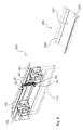
- Fig. 1
- eine Ausführungsform einer Verkleidungshalterung,
- Fig. 2
- die Ausführungsform der
Fig. 1 in seitlicher Darstellung, - Fig. 3
- die Ausführungsform der
Fig. 1 und2 mit befestigter Verkleidung, - Fig. 4
- in seitlicher Darstellung die Ausführungsform der
Fig. 1 bis 3 in montierter Position an der Rollenlaufbahn, - Fig. 5
- die Situation während dem Einsetzen des Halteabschnitts,
- Fig. 6
- die Situation während der Durchführung der ersten Befestigungsbewegung,
- Fig. 7
- die Situation während der Durchführung der zweiten Befestigungsbewegung und
- Fig. 8
- die Situation kurz vor der Durchführung der Montage.
- Fig. 1
- an embodiment of a fairing mount,
- Fig. 2
- the embodiment of the
Fig. 1 in lateral view, - Fig. 3
- the embodiment of the
Fig. 1 and2 with attached panel, - Fig. 4
- in side view, the embodiment of the
Fig. 1 to 3 in mounted position on the roller track, - Fig. 5
- the situation during the insertion of the holding section,
- Fig. 6
- the situation during the execution of the first fastening movement,
- Fig. 7
- the situation during the implementation of the second attachment movement and
- Fig. 8
- the situation just before the assembly.
In der
Die beiden Befestigungsabschnitte 40 und 50 sind hier mit einer Schnapp-Rast-Funktionalität ausgestattet. Das bedeutet, dass der erste Befestigungsabschnitt 40 einen ersten Befestigungsschenkel 42 und einen zweiten Befestigungsschenkel 44, hier zwei Befestigungsschenkel 44, aufweist. In gleicher Weise ist der zweite Befestigungsabschnitt 50 mit einem ersten Befestigungsschenkel 52 bzw. zwei solcher zweiter Befestigungsschenkel 52 und einem zweiten Befestigungsschenkel 54 ausgestattet.The two mounting
Darüber hinaus ist zu erkennen, dass der Grundkörper 20 eine im Wesentlichen flächige Längserstreckung aufweist, die auf der Rückseite mit einer Anlagefläche 22 zur Verfügung gestellt wird. Die Schwerkraftrichtung SKR ist dabei bezogen auf die entsprechende Montagesituation im Einbau einer solchen Verkleidungshalterung 10.In addition, it can be seen that the
Ebenfalls in
In den
Anhand der
Anschließend erfolgt das Befestigen der Verkleidung 200. Die Verkleidung 200 ist in der
Die voranstehende Beschreibung der Montagebewegung kann auch in umgekehrter Reihenfolge durchgeführt werden, um in erfindungsgemäßer Weise auch eine Demontage der Verkleidung gewährleisten zu können.The above description of the assembly movement can also be carried out in the reverse order to ensure disassembly of the panel in accordance with the invention.
Die voranstehende Erläuterung der Ausführungsformen beschreibt die vorliegende Erfindung ausschließlich im Rahmen von Beispielen. Dabei können einzelne Merkmale der Ausführungsformen, sofern technisch sinnvoll, frei miteinander kombiniert werden, ohne den Rahmen der vorliegenden Erfindung zu verlassen.The above explanation of the embodiments describes the present invention solely by way of example. In this case, individual features of the embodiments, if technically feasible, can be combined freely with one another, without departing from the scope of the present invention.
- 1010
- Verkleidungshalterungpanel mount
- 2020
- Grundkörperbody
- 2222
- Anlageflächecontact surface
- 3030
- Halteabschnittholding section
- 3232
- Verstärkungsrippereinforcing rib
- 4040
- erster Befestigungsabschnittfirst attachment section
- 4242
- erster Befestigungsschenkelfirst mounting leg
- 4444
- zweiter Befestigungsschenkelsecond mounting leg
- 5050
- zweiter Befestigungsabschnittsecond attachment section
- 5252
- erster Befestigungsschenkelfirst mounting leg
- 5454
- zweiter Befestigungsschenkelsecond mounting leg
- 100100
- Schiebetürenanlagesliding system
- 110110
- Schiebetürsliding door
- 120120
- RollenlaufbahnRoller track
- 130130
- Haltenutretaining groove
- 140140
- Rollenwagenroller carriage
- 200200
- Verkleidungpaneling
- 222222
- GegenanlageflächeAnvil surface
- 240240
- erster Gegenbefestigungsabschnittfirst counter-fastening section
- 250250
- zweiter Gegenbefestigungsabschnittsecond counter-fastening section
- SKRSKR
- SchwerkraftrichtungThe direction of gravity
- B1B1
- erste Befestigungsrichtungfirst attachment direction
- B2B2
- zweite Befestigungsrichtungsecond attachment direction
- αα
- Korrelationswinkelcorrelation angle
- ββ
- Befestigungswinkelmounting brackets
Claims (15)
Priority Applications (4)
| Application Number | Priority Date | Filing Date | Title |
|---|---|---|---|
| EP14193365.5A EP3020903B1 (en) | 2014-11-14 | 2014-11-14 | Cover fastener |
| ES14193365T ES2904831T3 (en) | 2014-11-14 | 2014-11-14 | lining support |
| US14/939,045 US20160138316A1 (en) | 2014-11-14 | 2015-11-12 | Cover holder |
| CN201510779359.8A CN105604429B (en) | 2014-11-14 | 2015-11-13 | Coating member holding meanss |
Applications Claiming Priority (1)
| Application Number | Priority Date | Filing Date | Title |
|---|---|---|---|
| EP14193365.5A EP3020903B1 (en) | 2014-11-14 | 2014-11-14 | Cover fastener |
Publications (2)
| Publication Number | Publication Date |
|---|---|
| EP3020903A1 true EP3020903A1 (en) | 2016-05-18 |
| EP3020903B1 EP3020903B1 (en) | 2021-11-10 |
Family
ID=51900781
Family Applications (1)
| Application Number | Title | Priority Date | Filing Date |
|---|---|---|---|
| EP14193365.5A Active EP3020903B1 (en) | 2014-11-14 | 2014-11-14 | Cover fastener |
Country Status (4)
| Country | Link |
|---|---|
| US (1) | US20160138316A1 (en) |
| EP (1) | EP3020903B1 (en) |
| CN (1) | CN105604429B (en) |
| ES (1) | ES2904831T3 (en) |
Families Citing this family (2)
| Publication number | Priority date | Publication date | Assignee | Title |
|---|---|---|---|---|
| PL3569806T3 (en) * | 2018-05-17 | 2022-01-17 | Kesseböhmer Holding Kg | Lid fitting for swingable mounting of a furniture lid to a furniture unit |
| GB2600162B (en) * | 2020-10-26 | 2023-04-26 | Blindspace Ab | A cover arrangement |
Citations (3)
| Publication number | Priority date | Publication date | Assignee | Title |
|---|---|---|---|---|
| EP2453087A1 (en) * | 2010-11-16 | 2012-05-16 | Eledyna Technology Corp. | Chassis structure having cover retaining mechanism |
| DE102012203726B3 (en) * | 2012-03-09 | 2013-06-06 | Geze Gmbh | sliding door assembly |
| FR2997992A1 (en) * | 2012-11-12 | 2014-05-16 | Financ Tirard Sas | Installation for closing e.g. door with sliding flap in partition, in building, has reserve groove with single rail, and reserve leg allowed to penetrate in reserve groove so as retain carriage in raising position with regard to rail |
Family Cites Families (19)
| Publication number | Priority date | Publication date | Assignee | Title |
|---|---|---|---|---|
| US3473266A (en) * | 1967-12-15 | 1969-10-21 | Stanley Works | Integrated header |
| US3983600A (en) * | 1976-02-20 | 1976-10-05 | Arthur Cox & Sons Inc. | By-passing door fascia assembly |
| DE9007691U1 (en) * | 1990-05-17 | 1994-04-14 | Hespe & Woelm Gmbh & Co Kg | sliding door |
| US5274499A (en) * | 1992-09-04 | 1993-12-28 | Draper Shade & Screen Co., Inc. | Battery operated projection screen with spring assisted roller and replaceable fascia |
| US6111694A (en) * | 1997-05-23 | 2000-08-29 | Draper, Inc. | Casing for projection screen system |
| DE19804860C1 (en) * | 1998-02-09 | 1999-08-26 | Dorma Gmbh & Co Kg | Housing, in particular for automatic door drives |
| DE29807556U1 (en) * | 1998-04-30 | 1999-06-02 | Automatik Tuer Systeme Gmbh | Sliding door system |
| US6983512B2 (en) * | 2002-07-23 | 2006-01-10 | Masco Corporation | Movable door mounting assembly with trolley locking structure |
| FR2849092B1 (en) * | 2002-12-20 | 2005-02-18 | Portalp Internat | DEVICE FOR SUSPENDING AND GUIDING A MOBILE VANTAIL. |
| US7228659B2 (en) * | 2004-01-09 | 2007-06-12 | Overhead Door Corporation | Sliding door reinforced frame header with movable cover |
| DE102004062995B4 (en) * | 2004-12-22 | 2007-01-18 | Dorma Gmbh + Co. Kg | Manual release unit for a sliding door |
| USD558569S1 (en) * | 2006-05-24 | 2008-01-01 | Hydroscreen Pty Ltd | Sliding screen track |
| EP2151538B8 (en) * | 2008-08-06 | 2017-05-03 | Hawa Sliding Solutions AG | Device with a sliding guide for supporting panels, sliding guide, guide rail and partition element |
| DE202009009548U1 (en) * | 2009-07-10 | 2009-09-10 | Dorma Gmbh + Co. Kg | Ceiling rail system for guiding wall elements |
| CN202899936U (en) * | 2012-10-17 | 2013-04-24 | 周裕佳 | Single door structure of shower room |
| JPWO2014112372A1 (en) * | 2013-01-18 | 2017-01-19 | ナブテスコ株式会社 | Automatic door device and drive mechanism exterior body |
| CN203430249U (en) * | 2013-07-09 | 2014-02-12 | 周裕佳 | Sliding structure for sliding door body |
| CN203452516U (en) * | 2013-08-26 | 2014-02-26 | 中国船舶重工集团公司第七一三研究所 | Guide hanging device |
| CN203603707U (en) * | 2013-09-30 | 2014-05-21 | 中山市启高卫浴设备有限公司 | Linkage door |
-
2014
- 2014-11-14 EP EP14193365.5A patent/EP3020903B1/en active Active
- 2014-11-14 ES ES14193365T patent/ES2904831T3/en active Active
-
2015
- 2015-11-12 US US14/939,045 patent/US20160138316A1/en not_active Abandoned
- 2015-11-13 CN CN201510779359.8A patent/CN105604429B/en not_active Expired - Fee Related
Patent Citations (3)
| Publication number | Priority date | Publication date | Assignee | Title |
|---|---|---|---|---|
| EP2453087A1 (en) * | 2010-11-16 | 2012-05-16 | Eledyna Technology Corp. | Chassis structure having cover retaining mechanism |
| DE102012203726B3 (en) * | 2012-03-09 | 2013-06-06 | Geze Gmbh | sliding door assembly |
| FR2997992A1 (en) * | 2012-11-12 | 2014-05-16 | Financ Tirard Sas | Installation for closing e.g. door with sliding flap in partition, in building, has reserve groove with single rail, and reserve leg allowed to penetrate in reserve groove so as retain carriage in raising position with regard to rail |
Also Published As
| Publication number | Publication date |
|---|---|
| CN105604429A (en) | 2016-05-25 |
| CN105604429B (en) | 2019-04-16 |
| EP3020903B1 (en) | 2021-11-10 |
| ES2904831T3 (en) | 2022-04-06 |
| US20160138316A1 (en) | 2016-05-19 |
Similar Documents
| Publication | Publication Date | Title |
|---|---|---|
| DE112007000086B4 (en) | Connection arrangement with a connection element | |
| WO2012038253A1 (en) | Mounting system | |
| EP2019765A1 (en) | Device and method for fastening a wiper motor to a wiper linkage | |
| EP2935739B1 (en) | Cover device for a retaining jaws module that can be detachably coupled to a striker plate module to bring about the connection of a vehicle door and a side wall frame of a vehicle body | |
| EP3009692B1 (en) | Moveable furniture part and connecting device | |
| EP3020903B1 (en) | Cover fastener | |
| EP3195773B1 (en) | Glass sliding door | |
| EP3045628B1 (en) | Path device for the sliding mounting of at least one first roller cart and at least one second roller cart | |
| EP2787265B1 (en) | Corner angle | |
| DE102015209321A1 (en) | Cable duct arrangement with connection unit and holding part | |
| DE102016011744B3 (en) | Holding device for a Außenbeplankungselement of a motor vehicle, motor vehicle and method for actuating a holding device | |
| DE202007014791U1 (en) | Lifting column | |
| DE102013223358A1 (en) | Device for attaching a decorative strip to a vehicle outer skin element, trim strip and vehicle outer skin element | |
| EP1693252B1 (en) | Mounting mechanism | |
| EP3140174B1 (en) | Vehicle, in particular rail vehicle, with a mounting rail | |
| DE102013100308A1 (en) | Bar fitting for a window or a door | |
| EP3091158B1 (en) | Housing of a sliding door assembly | |
| DE102012022310B4 (en) | Arrangement of an attachment or assembly part on a support structure and method for its assembly | |
| EP2026436A2 (en) | Insulating profile | |
| DE102007050632A1 (en) | Lifting column for e.g. changing height of table top, has sliding elements fastened to inner profile and taken up over bar e.g. form-stable bar, in notch of inner profile, where sliding elements slide over outer profile | |
| DE202016103609U1 (en) | Adapter for mounting on a fixed point of a vehicle | |
| DE102020126090A1 (en) | Window track, window track assembly and method of manufacture | |
| EP3325744B1 (en) | Method for disassembling a guide arrangement for a sliding door | |
| EP3045617B1 (en) | Rosette and assembly of a door or window handle and a rosette on a receiving opening of a door leaf, a window leaf or the like | |
| DE102015226051B4 (en) | Arrangement of a headlight relative to a carrier element fixed on the bodyshell and method for fine adjustment of a detachably fastened headlight relative to a carrier element of a motor vehicle fixed on the bodyshell side |
Legal Events
| Date | Code | Title | Description |
|---|---|---|---|
| PUAI | Public reference made under article 153(3) epc to a published international application that has entered the european phase |
Free format text: ORIGINAL CODE: 0009012 |
|
| AK | Designated contracting states |
Kind code of ref document: A1 Designated state(s): AL AT BE BG CH CY CZ DE DK EE ES FI FR GB GR HR HU IE IS IT LI LT LU LV MC MK MT NL NO PL PT RO RS SE SI SK SM TR |
|
| AX | Request for extension of the european patent |
Extension state: BA ME |
|
| 17P | Request for examination filed |
Effective date: 20160830 |
|
| RBV | Designated contracting states (corrected) |
Designated state(s): AL AT BE BG CH CY CZ DE DK EE ES FI FR GB GR HR HU IE IS IT LI LT LU LV MC MK MT NL NO PL PT RO RS SE SI SK SM TR |
|
| RAP1 | Party data changed (applicant data changed or rights of an application transferred) |
Owner name: DORMAKABA DEUTSCHLAND GMBH |
|
| STAA | Information on the status of an ep patent application or granted ep patent |
Free format text: STATUS: EXAMINATION IS IN PROGRESS |
|
| 17Q | First examination report despatched |
Effective date: 20180716 |
|
| GRAP | Despatch of communication of intention to grant a patent |
Free format text: ORIGINAL CODE: EPIDOSNIGR1 |
|
| STAA | Information on the status of an ep patent application or granted ep patent |
Free format text: STATUS: GRANT OF PATENT IS INTENDED |
|
| INTG | Intention to grant announced |
Effective date: 20191028 |
|
| GRAS | Grant fee paid |
Free format text: ORIGINAL CODE: EPIDOSNIGR3 |
|
| GRAJ | Information related to disapproval of communication of intention to grant by the applicant or resumption of examination proceedings by the epo deleted |
Free format text: ORIGINAL CODE: EPIDOSDIGR1 |
|
| GRAL | Information related to payment of fee for publishing/printing deleted |
Free format text: ORIGINAL CODE: EPIDOSDIGR3 |
|
| STAA | Information on the status of an ep patent application or granted ep patent |
Free format text: STATUS: EXAMINATION IS IN PROGRESS |
|
| INTC | Intention to grant announced (deleted) | ||
| STAA | Information on the status of an ep patent application or granted ep patent |
Free format text: STATUS: EXAMINATION IS IN PROGRESS |
|
| GRAP | Despatch of communication of intention to grant a patent |
Free format text: ORIGINAL CODE: EPIDOSNIGR1 |
|
| STAA | Information on the status of an ep patent application or granted ep patent |
Free format text: STATUS: GRANT OF PATENT IS INTENDED |
|
| INTG | Intention to grant announced |
Effective date: 20210611 |
|
| GRAS | Grant fee paid |
Free format text: ORIGINAL CODE: EPIDOSNIGR3 |
|
| GRAA | (expected) grant |
Free format text: ORIGINAL CODE: 0009210 |
|
| STAA | Information on the status of an ep patent application or granted ep patent |
Free format text: STATUS: THE PATENT HAS BEEN GRANTED |
|
| AK | Designated contracting states |
Kind code of ref document: B1 Designated state(s): AL AT BE BG CH CY CZ DE DK EE ES FI FR GB GR HR HU IE IS IT LI LT LU LV MC MK MT NL NO PL PT RO RS SE SI SK SM TR |
|
| REG | Reference to a national code |
Ref country code: GB Ref legal event code: FG4D Free format text: NOT ENGLISH |
|
| REG | Reference to a national code |
Ref country code: AT Ref legal event code: REF Ref document number: 1446256 Country of ref document: AT Kind code of ref document: T Effective date: 20211115 Ref country code: CH Ref legal event code: EP |
|
| REG | Reference to a national code |
Ref country code: DE Ref legal event code: R096 Ref document number: 502014015975 Country of ref document: DE |
|
| REG | Reference to a national code |
Ref country code: IE Ref legal event code: FG4D Free format text: LANGUAGE OF EP DOCUMENT: GERMAN |
|
| REG | Reference to a national code |
Ref country code: DE Ref legal event code: R081 Ref document number: 502014015975 Country of ref document: DE Owner name: DORMA-GLAS GMBH, DE Free format text: FORMER OWNER: DORMAKABA DEUTSCHLAND GMBH, 58256 ENNEPETAL, DE |
|
| RAP2 | Party data changed (patent owner data changed or rights of a patent transferred) |
Owner name: DORMA-GLAS GMBH |
|
| REG | Reference to a national code |
Ref country code: GB Ref legal event code: 732E Free format text: REGISTERED BETWEEN 20220210 AND 20220216 |
|
| REG | Reference to a national code |
Ref country code: LT Ref legal event code: MG9D |
|
| REG | Reference to a national code |
Ref country code: NL Ref legal event code: MP Effective date: 20211110 |
|
| REG | Reference to a national code |
Ref country code: ES Ref legal event code: FG2A Ref document number: 2904831 Country of ref document: ES Kind code of ref document: T3 Effective date: 20220406 |
|
| PG25 | Lapsed in a contracting state [announced via postgrant information from national office to epo] |
Ref country code: RS Free format text: LAPSE BECAUSE OF FAILURE TO SUBMIT A TRANSLATION OF THE DESCRIPTION OR TO PAY THE FEE WITHIN THE PRESCRIBED TIME-LIMIT Effective date: 20211110 Ref country code: LT Free format text: LAPSE BECAUSE OF FAILURE TO SUBMIT A TRANSLATION OF THE DESCRIPTION OR TO PAY THE FEE WITHIN THE PRESCRIBED TIME-LIMIT Effective date: 20211110 Ref country code: FI Free format text: LAPSE BECAUSE OF FAILURE TO SUBMIT A TRANSLATION OF THE DESCRIPTION OR TO PAY THE FEE WITHIN THE PRESCRIBED TIME-LIMIT Effective date: 20211110 Ref country code: BG Free format text: LAPSE BECAUSE OF FAILURE TO SUBMIT A TRANSLATION OF THE DESCRIPTION OR TO PAY THE FEE WITHIN THE PRESCRIBED TIME-LIMIT Effective date: 20220210 |
|
| REG | Reference to a national code |
Ref country code: AT Ref legal event code: PC Ref document number: 1446256 Country of ref document: AT Kind code of ref document: T Owner name: DORMA GLAS GMBH, DE Effective date: 20220405 |
|
| PG25 | Lapsed in a contracting state [announced via postgrant information from national office to epo] |
Ref country code: IS Free format text: LAPSE BECAUSE OF FAILURE TO SUBMIT A TRANSLATION OF THE DESCRIPTION OR TO PAY THE FEE WITHIN THE PRESCRIBED TIME-LIMIT Effective date: 20220310 Ref country code: SE Free format text: LAPSE BECAUSE OF FAILURE TO SUBMIT A TRANSLATION OF THE DESCRIPTION OR TO PAY THE FEE WITHIN THE PRESCRIBED TIME-LIMIT Effective date: 20211110 Ref country code: PT Free format text: LAPSE BECAUSE OF FAILURE TO SUBMIT A TRANSLATION OF THE DESCRIPTION OR TO PAY THE FEE WITHIN THE PRESCRIBED TIME-LIMIT Effective date: 20220310 Ref country code: PL Free format text: LAPSE BECAUSE OF FAILURE TO SUBMIT A TRANSLATION OF THE DESCRIPTION OR TO PAY THE FEE WITHIN THE PRESCRIBED TIME-LIMIT Effective date: 20211110 Ref country code: NO Free format text: LAPSE BECAUSE OF FAILURE TO SUBMIT A TRANSLATION OF THE DESCRIPTION OR TO PAY THE FEE WITHIN THE PRESCRIBED TIME-LIMIT Effective date: 20220210 Ref country code: NL Free format text: LAPSE BECAUSE OF FAILURE TO SUBMIT A TRANSLATION OF THE DESCRIPTION OR TO PAY THE FEE WITHIN THE PRESCRIBED TIME-LIMIT Effective date: 20211110 Ref country code: LV Free format text: LAPSE BECAUSE OF FAILURE TO SUBMIT A TRANSLATION OF THE DESCRIPTION OR TO PAY THE FEE WITHIN THE PRESCRIBED TIME-LIMIT Effective date: 20211110 Ref country code: HR Free format text: LAPSE BECAUSE OF FAILURE TO SUBMIT A TRANSLATION OF THE DESCRIPTION OR TO PAY THE FEE WITHIN THE PRESCRIBED TIME-LIMIT Effective date: 20211110 Ref country code: GR Free format text: LAPSE BECAUSE OF FAILURE TO SUBMIT A TRANSLATION OF THE DESCRIPTION OR TO PAY THE FEE WITHIN THE PRESCRIBED TIME-LIMIT Effective date: 20220211 |
|
| REG | Reference to a national code |
Ref country code: CH Ref legal event code: PL |
|
| PG25 | Lapsed in a contracting state [announced via postgrant information from national office to epo] |
Ref country code: SM Free format text: LAPSE BECAUSE OF FAILURE TO SUBMIT A TRANSLATION OF THE DESCRIPTION OR TO PAY THE FEE WITHIN THE PRESCRIBED TIME-LIMIT Effective date: 20211110 Ref country code: SK Free format text: LAPSE BECAUSE OF FAILURE TO SUBMIT A TRANSLATION OF THE DESCRIPTION OR TO PAY THE FEE WITHIN THE PRESCRIBED TIME-LIMIT Effective date: 20211110 Ref country code: RO Free format text: LAPSE BECAUSE OF FAILURE TO SUBMIT A TRANSLATION OF THE DESCRIPTION OR TO PAY THE FEE WITHIN THE PRESCRIBED TIME-LIMIT Effective date: 20211110 Ref country code: LU Free format text: LAPSE BECAUSE OF NON-PAYMENT OF DUE FEES Effective date: 20211114 Ref country code: EE Free format text: LAPSE BECAUSE OF FAILURE TO SUBMIT A TRANSLATION OF THE DESCRIPTION OR TO PAY THE FEE WITHIN THE PRESCRIBED TIME-LIMIT Effective date: 20211110 Ref country code: DK Free format text: LAPSE BECAUSE OF FAILURE TO SUBMIT A TRANSLATION OF THE DESCRIPTION OR TO PAY THE FEE WITHIN THE PRESCRIBED TIME-LIMIT Effective date: 20211110 Ref country code: CZ Free format text: LAPSE BECAUSE OF FAILURE TO SUBMIT A TRANSLATION OF THE DESCRIPTION OR TO PAY THE FEE WITHIN THE PRESCRIBED TIME-LIMIT Effective date: 20211110 Ref country code: BE Free format text: LAPSE BECAUSE OF NON-PAYMENT OF DUE FEES Effective date: 20211130 |
|
| REG | Reference to a national code |
Ref country code: BE Ref legal event code: MM Effective date: 20211130 |
|
| REG | Reference to a national code |
Ref country code: DE Ref legal event code: R026 Ref document number: 502014015975 Country of ref document: DE |
|
| PLBI | Opposition filed |
Free format text: ORIGINAL CODE: 0009260 |
|
| PLAX | Notice of opposition and request to file observation + time limit sent |
Free format text: ORIGINAL CODE: EPIDOSNOBS2 |
|
| PG25 | Lapsed in a contracting state [announced via postgrant information from national office to epo] |
Ref country code: MC Free format text: LAPSE BECAUSE OF FAILURE TO SUBMIT A TRANSLATION OF THE DESCRIPTION OR TO PAY THE FEE WITHIN THE PRESCRIBED TIME-LIMIT Effective date: 20211110 |
|
| 26 | Opposition filed |
Opponent name: GEZE GMBH Effective date: 20220810 |
|
| PG25 | Lapsed in a contracting state [announced via postgrant information from national office to epo] |
Ref country code: IE Free format text: LAPSE BECAUSE OF NON-PAYMENT OF DUE FEES Effective date: 20211114 Ref country code: AL Free format text: LAPSE BECAUSE OF FAILURE TO SUBMIT A TRANSLATION OF THE DESCRIPTION OR TO PAY THE FEE WITHIN THE PRESCRIBED TIME-LIMIT Effective date: 20211110 |
|
| PG25 | Lapsed in a contracting state [announced via postgrant information from national office to epo] |
Ref country code: SI Free format text: LAPSE BECAUSE OF FAILURE TO SUBMIT A TRANSLATION OF THE DESCRIPTION OR TO PAY THE FEE WITHIN THE PRESCRIBED TIME-LIMIT Effective date: 20211110 |
|
| PGFP | Annual fee paid to national office [announced via postgrant information from national office to epo] |
Ref country code: ES Payment date: 20230125 Year of fee payment: 9 |
|
| PG25 | Lapsed in a contracting state [announced via postgrant information from national office to epo] |
Ref country code: HU Free format text: LAPSE BECAUSE OF FAILURE TO SUBMIT A TRANSLATION OF THE DESCRIPTION OR TO PAY THE FEE WITHIN THE PRESCRIBED TIME-LIMIT; INVALID AB INITIO Effective date: 20141114 |
|
| PG25 | Lapsed in a contracting state [announced via postgrant information from national office to epo] |
Ref country code: CY Free format text: LAPSE BECAUSE OF FAILURE TO SUBMIT A TRANSLATION OF THE DESCRIPTION OR TO PAY THE FEE WITHIN THE PRESCRIBED TIME-LIMIT Effective date: 20211110 |
|
| PG25 | Lapsed in a contracting state [announced via postgrant information from national office to epo] |
Ref country code: LI Free format text: LAPSE BECAUSE OF NON-PAYMENT OF DUE FEES Effective date: 20220630 Ref country code: CH Free format text: LAPSE BECAUSE OF NON-PAYMENT OF DUE FEES Effective date: 20220630 |
|
| PGFP | Annual fee paid to national office [announced via postgrant information from national office to epo] |
Ref country code: GB Payment date: 20231123 Year of fee payment: 10 |
|
| PGFP | Annual fee paid to national office [announced via postgrant information from national office to epo] |
Ref country code: IT Payment date: 20231124 Year of fee payment: 10 Ref country code: FR Payment date: 20231120 Year of fee payment: 10 Ref country code: DE Payment date: 20231121 Year of fee payment: 10 Ref country code: AT Payment date: 20231121 Year of fee payment: 10 |
|
| PGFP | Annual fee paid to national office [announced via postgrant information from national office to epo] |
Ref country code: ES Payment date: 20240129 Year of fee payment: 10 |