EP3020898A1 - Roller carriage for mounting a sliding door - Google Patents
Roller carriage for mounting a sliding door Download PDFInfo
- Publication number
- EP3020898A1 EP3020898A1 EP14193359.8A EP14193359A EP3020898A1 EP 3020898 A1 EP3020898 A1 EP 3020898A1 EP 14193359 A EP14193359 A EP 14193359A EP 3020898 A1 EP3020898 A1 EP 3020898A1
- Authority
- EP
- European Patent Office
- Prior art keywords
- roller
- modulus
- roller carriage
- sliding door
- sound
- Prior art date
- Legal status (The legal status is an assumption and is not a legal conclusion. Google has not performed a legal analysis and makes no representation as to the accuracy of the status listed.)
- Granted
Links
- 239000000463 material Substances 0.000 claims abstract description 112
- 239000011521 glass Substances 0.000 claims description 29
- 230000005540 biological transmission Effects 0.000 claims description 16
- 238000013016 damping Methods 0.000 description 31
- 230000033001 locomotion Effects 0.000 description 15
- 230000000295 complement effect Effects 0.000 description 14
- 230000000694 effects Effects 0.000 description 10
- 230000006870 function Effects 0.000 description 9
- 230000008901 benefit Effects 0.000 description 6
- 230000001976 improved effect Effects 0.000 description 6
- 230000015572 biosynthetic process Effects 0.000 description 4
- 230000005484 gravity Effects 0.000 description 2
- 230000013011 mating Effects 0.000 description 2
- 230000009467 reduction Effects 0.000 description 2
- 238000001228 spectrum Methods 0.000 description 2
- 230000009471 action Effects 0.000 description 1
- 230000002238 attenuated effect Effects 0.000 description 1
- 150000001875 compounds Chemical class 0.000 description 1
- 230000001419 dependent effect Effects 0.000 description 1
- 238000009434 installation Methods 0.000 description 1
- 238000004519 manufacturing process Methods 0.000 description 1
- 230000008447 perception Effects 0.000 description 1
- 230000002265 prevention Effects 0.000 description 1
- 230000002787 reinforcement Effects 0.000 description 1
- 230000003014 reinforcing effect Effects 0.000 description 1
- 238000005096 rolling process Methods 0.000 description 1
- 230000007704 transition Effects 0.000 description 1
Images


Classifications
-
- E—FIXED CONSTRUCTIONS
- E05—LOCKS; KEYS; WINDOW OR DOOR FITTINGS; SAFES
- E05D—HINGES OR SUSPENSION DEVICES FOR DOORS, WINDOWS OR WINGS
- E05D15/00—Suspension arrangements for wings
- E05D15/06—Suspension arrangements for wings for wings sliding horizontally more or less in their own plane
- E05D15/0621—Details, e.g. suspension or supporting guides
- E05D15/0626—Details, e.g. suspension or supporting guides for wings suspended at the top
- E05D15/0643—Details, e.g. suspension or supporting guides for wings suspended at the top on balls or floating rollers
-
- E—FIXED CONSTRUCTIONS
- E05—LOCKS; KEYS; WINDOW OR DOOR FITTINGS; SAFES
- E05D—HINGES OR SUSPENSION DEVICES FOR DOORS, WINDOWS OR WINGS
- E05D15/00—Suspension arrangements for wings
- E05D15/06—Suspension arrangements for wings for wings sliding horizontally more or less in their own plane
- E05D15/0621—Details, e.g. suspension or supporting guides
- E05D15/0626—Details, e.g. suspension or supporting guides for wings suspended at the top
- E05D15/063—Details, e.g. suspension or supporting guides for wings suspended at the top on wheels with fixed axis
- E05D15/0634—Details, e.g. suspension or supporting guides for wings suspended at the top on wheels with fixed axis with height adjustment
-
- E—FIXED CONSTRUCTIONS
- E05—LOCKS; KEYS; WINDOW OR DOOR FITTINGS; SAFES
- E05D—HINGES OR SUSPENSION DEVICES FOR DOORS, WINDOWS OR WINGS
- E05D15/00—Suspension arrangements for wings
- E05D15/06—Suspension arrangements for wings for wings sliding horizontally more or less in their own plane
- E05D15/0621—Details, e.g. suspension or supporting guides
- E05D15/0626—Details, e.g. suspension or supporting guides for wings suspended at the top
- E05D15/0647—Details, e.g. suspension or supporting guides for wings suspended at the top on sliding blocks
-
- E—FIXED CONSTRUCTIONS
- E05—LOCKS; KEYS; WINDOW OR DOOR FITTINGS; SAFES
- E05D—HINGES OR SUSPENSION DEVICES FOR DOORS, WINDOWS OR WINGS
- E05D15/00—Suspension arrangements for wings
- E05D15/06—Suspension arrangements for wings for wings sliding horizontally more or less in their own plane
- E05D15/0621—Details, e.g. suspension or supporting guides
- E05D15/0626—Details, e.g. suspension or supporting guides for wings suspended at the top
- E05D15/0652—Tracks
-
- E—FIXED CONSTRUCTIONS
- E06—DOORS, WINDOWS, SHUTTERS, OR ROLLER BLINDS IN GENERAL; LADDERS
- E06B—FIXED OR MOVABLE CLOSURES FOR OPENINGS IN BUILDINGS, VEHICLES, FENCES OR LIKE ENCLOSURES IN GENERAL, e.g. DOORS, WINDOWS, BLINDS, GATES
- E06B3/00—Window sashes, door leaves, or like elements for closing wall or like openings; Layout of fixed or moving closures, e.g. windows in wall or like openings; Features of rigidly-mounted outer frames relating to the mounting of wing frames
- E06B3/32—Arrangements of wings characterised by the manner of movement; Arrangements of movable wings in openings; Features of wings or frames relating solely to the manner of movement of the wing
- E06B3/34—Arrangements of wings characterised by the manner of movement; Arrangements of movable wings in openings; Features of wings or frames relating solely to the manner of movement of the wing with only one kind of movement
- E06B3/42—Sliding wings; Details of frames with respect to guiding
- E06B3/46—Horizontally-sliding wings
- E06B3/4636—Horizontally-sliding wings for doors
-
- E—FIXED CONSTRUCTIONS
- E06—DOORS, WINDOWS, SHUTTERS, OR ROLLER BLINDS IN GENERAL; LADDERS
- E06B—FIXED OR MOVABLE CLOSURES FOR OPENINGS IN BUILDINGS, VEHICLES, FENCES OR LIKE ENCLOSURES IN GENERAL, e.g. DOORS, WINDOWS, BLINDS, GATES
- E06B3/00—Window sashes, door leaves, or like elements for closing wall or like openings; Layout of fixed or moving closures, e.g. windows in wall or like openings; Features of rigidly-mounted outer frames relating to the mounting of wing frames
- E06B3/32—Arrangements of wings characterised by the manner of movement; Arrangements of movable wings in openings; Features of wings or frames relating solely to the manner of movement of the wing
- E06B3/34—Arrangements of wings characterised by the manner of movement; Arrangements of movable wings in openings; Features of wings or frames relating solely to the manner of movement of the wing with only one kind of movement
- E06B3/42—Sliding wings; Details of frames with respect to guiding
- E06B3/46—Horizontally-sliding wings
- E06B3/4681—Horizontally-sliding wings made of glass panes without frames
-
- E—FIXED CONSTRUCTIONS
- E06—DOORS, WINDOWS, SHUTTERS, OR ROLLER BLINDS IN GENERAL; LADDERS
- E06B—FIXED OR MOVABLE CLOSURES FOR OPENINGS IN BUILDINGS, VEHICLES, FENCES OR LIKE ENCLOSURES IN GENERAL, e.g. DOORS, WINDOWS, BLINDS, GATES
- E06B3/00—Window sashes, door leaves, or like elements for closing wall or like openings; Layout of fixed or moving closures, e.g. windows in wall or like openings; Features of rigidly-mounted outer frames relating to the mounting of wing frames
- E06B3/54—Fixing of glass panes or like plates
- E06B3/5454—Fixing of glass panes or like plates inside U-shaped section members
-
- E—FIXED CONSTRUCTIONS
- E06—DOORS, WINDOWS, SHUTTERS, OR ROLLER BLINDS IN GENERAL; LADDERS
- E06B—FIXED OR MOVABLE CLOSURES FOR OPENINGS IN BUILDINGS, VEHICLES, FENCES OR LIKE ENCLOSURES IN GENERAL, e.g. DOORS, WINDOWS, BLINDS, GATES
- E06B5/00—Doors, windows, or like closures for special purposes; Border constructions therefor
- E06B5/20—Doors, windows, or like closures for special purposes; Border constructions therefor for insulation against noise
-
- E—FIXED CONSTRUCTIONS
- E05—LOCKS; KEYS; WINDOW OR DOOR FITTINGS; SAFES
- E05Y—INDEXING SCHEME RELATING TO HINGES OR OTHER SUSPENSION DEVICES FOR DOORS, WINDOWS OR WINGS AND DEVICES FOR MOVING WINGS INTO OPEN OR CLOSED POSITION, CHECKS FOR WINGS AND WING FITTINGS NOT OTHERWISE PROVIDED FOR, CONCERNED WITH THE FUNCTIONING OF THE WING
- E05Y2800/00—Details, accessories and auxiliary operations not otherwise provided for
- E05Y2800/40—Protection
- E05Y2800/422—Protection against vibration or noise
-
- E—FIXED CONSTRUCTIONS
- E05—LOCKS; KEYS; WINDOW OR DOOR FITTINGS; SAFES
- E05Y—INDEXING SCHEME RELATING TO HINGES OR OTHER SUSPENSION DEVICES FOR DOORS, WINDOWS OR WINGS AND DEVICES FOR MOVING WINGS INTO OPEN OR CLOSED POSITION, CHECKS FOR WINGS AND WING FITTINGS NOT OTHERWISE PROVIDED FOR, CONCERNED WITH THE FUNCTIONING OF THE WING
- E05Y2800/00—Details, accessories and auxiliary operations not otherwise provided for
- E05Y2800/67—Materials; Strength alteration thereof
- E05Y2800/68—Combinations of materials
Abstract
Die Erfindung betrifft einen Rollenwagen (10) für die Aufnahme einer Schiebetür (110), aufweisend ein Rollenmodul (20) zur verschiebbaren Anbringung an einer Rollenlaufbahn (120) und einen Grundkörper (30) zur Befestigung an der Schiebetür (110), wobei das Rollenmodul (20) aus einem ersten Material und der Grundkörper (30) aus einem zweiten Material ausgebildet ist, wobei das erste Material in einem ersten Schallleitbereich (I) Körperschall leitet und in einem zweiten Schallleitbereich (II) Körperschall dämpft sowie das zweite Material in dem ersten Schallleitbereich (I) Körperschall dämpft und in dem zweiten Schallleitbereich (II) Körperschall leitet.The invention relates to a roller carriage (10) for receiving a sliding door (110), comprising a roller module (20) for slidable attachment to a roller track (120) and a base body (30) for attachment to the sliding door (110), wherein the roller module (20) of a first material and the base body (30) is formed of a second material, wherein the first material in a first Schallleitbereich (I) directs structure-borne sound and in a second Schallleitbereich (II) attenuates structure-borne sound and the second material in the first Schallleitbereich (I) attenuates structure-borne sound and conducts structure-borne noise in the second Schallleitbereich (II).
Description
Die vorliegende Erfindung betrifft einen Rollenwagen für die Aufnahme einer Schiebetür sowie eine Schiebetürenanlage mit einer Rollenlaufbahn und wenigstens einem auf der Rollenlaufbahn verschiebbar gelagerten Rollenwagen.The present invention relates to a roller carriage for receiving a sliding door and a sliding door system with a roller track and at least one slidably mounted on the roller track roller carriage.
Es ist bekannt, dass für das Verschließen von Türen unterschiedliche Türarten eingesetzt werden können. Insbesondere sind dabei Schiebetüren verwendbar. Diese Schiebetüren sind üblicherweise mit Schiebetürblättern versehen, welche in entsprechenden Klemmvorrichtungen eines Rollenwagens gehalten werden. Um die Schiebefunktionalität zu gewährleisten, sind solche Rollenwagen in Rollenlaufbahnen eingesetzt, welche wiederum oberhalb der Türöffnung an der Wand und/oder der Decke befestigt sind. Bei den bekannten Lösungen wird also eine Bewegung durchgeführt zwischen einer geöffneten und einer geschlossenen Position der Schiebetür. Dabei laufen entsprechende Lagervorrichtungen, insbesondere Rollen, auf der Rollenlaufbahn ab. Während dieser Bewegung ist es möglich, dass Vibrationen von der Rollenlaufbahn in den Rollenwagen eingetragen werden. Auch ist es denkbar, dass von der Schiebetür Vibrationen in den Rollenlaufwagen eingebracht werden. Da hier häufig eine Vielzahl einzelner Bauteile miteinander kombiniert ist, und insbesondere die Verbindung zwischen dem Rollenwagen und der Rollenlaufbahn nur in einhängender Weise ausgebildet ist, kann diese jeweilige Vibration zur Geräuschemission führen. So wird der in dem jeweiligen Körper erzeugte und weitergeleitete Körperschall von zumindest einem der Körper abgegeben und auf diese Weise als akustische Frequenz von dem Nutzer der Schiebetürenanlage wahrnehmbar. Die voranstehend beschriebene Vibration kann sich dabei innerhalb des Gesamtsystems der Schiebetürenanlage verstärken und auf diese Weise den negativen Eindruck eines lauten Bewegens noch weiter verstärken. Die Lautstärke bei der Bewegung einer Schiebetür wird dabei vom Nutzer häufig als eines der Hauptkriterien wahrgenommen, wenn es um die Beurteilung der Qualität der Schiebetürenanlage geht. Somit stellt eine sich laut bewegende Schiebetür in der Wahrnehmung des Nutzers der Schiebetürenanlage ein schlechtes bzw. minderwertiges Produkt dar.It is known that different types of doors can be used for closing doors. In particular, sliding doors are used. These sliding doors are usually provided with sliding door leaves, which are held in corresponding clamping devices of a roller carriage. In order to ensure the sliding functionality, such roller carriages are used in roller races, which in turn are mounted above the door opening on the wall and / or the ceiling. In the known solutions, therefore, a movement is performed between an open and a closed position of the sliding door. In this case, corresponding storage devices, in particular rollers, run on the roller track. During this movement, it is possible that vibrations from the roller track are registered in the roller carriage. It is also conceivable that vibrations are introduced into the roller carriage from the sliding door. Since here often a plurality of individual components is combined, and in particular the connection between the roller carriage and the roller track is formed only in einhängender way, this particular vibration can lead to noise. Thus, the structure-borne noise generated and relayed in the respective body is emitted by at least one of the bodies and in this way as an acoustic frequency by the user the sliding door system perceptible. The vibration described above can thereby reinforce within the overall system of the sliding door system and in this way further enhance the negative impression of a loud moving. The volume when moving a sliding door is often perceived by the user as one of the main criteria when it comes to assessing the quality of the sliding door system. Thus, a loudly moving sliding door in the perception of the user of the sliding door system is a poor or inferior product.
Es ist Aufgabe der vorliegenden Erfindung, die voranstehend beschriebenen Nachteile zumindest teilweise zu beheben. Insbesondere ist es Aufgabe der vorliegenden Erfindung, in kostengünstiger und einfacher Weise die Laufruhe eines Rollenwagens zu verbessern.It is an object of the present invention to at least partially overcome the disadvantages described above. In particular, it is an object of the present invention to improve the quiet running of a roller carriage in a cost effective and simple manner.
Voranstehende Aufgabe wird gelöst durch einen Rollenwagen mit den Merkmalen des Anspruchs 1 sowie eine Schiebetürenanlage mit den Merkmalen des Anspruchs 13. Weitere Merkmale und Details der Erfindung ergeben sich aus den Unteransprüchen, der Beschreibung und den Zeichnungen. Dabei gelten Merkmale und Details, die im Zusammenhang mit dem erfindungsgemäßen Rollenwagen beschrieben sind, selbstverständlich auch im Zusammenhang mit der erfindungsgemäßen Schiebetürenanlage und jeweils umgekehrt, so dass bezüglich der Offenbarung zu den einzelnen Erfindungsaspekten stets wechselseitig Bezug genommen wird bzw. werden kann.The above object is achieved by a roller carriage with the features of claim 1 and a sliding door system with the features of claim 13. Further features and details of the invention will become apparent from the dependent claims, the description and the drawings. In this case, features and details that are described in connection with the roller carriage according to the invention apply, of course, also in connection with the sliding door system according to the invention and in each case vice versa, so that with respect to the disclosure of the individual aspects of the invention always reciprocal reference is or may be.
Erfindungsgemäß ist ein Rollenwagen für die Aufnahme einer Schiebetür vorgesehen. Dieser Rollenwagen weist ein Rollenmodul zur verschiebbaren Anbringung an einer Rollenbahn auf. Weiter ist ein Grundkörper zur Befestigung an der Schiebetür vorgesehen. Ein erfindungsgemäßer Rollenwagen zeichnet sich dadurch aus, dass das Rollenmodul aus einem ersten Material und der Grundkörper aus einem zweiten Material ausgebildet ist. Dabei leitet das erste Material in einem ersten Schallleitbereich Körperschall und in einem zweiten Schallleitbereich dämpft dieses erste Material den Körperschall. Das zweite Material leitet den Körperschall im zweiten Schallleitbereich und dämpft wiederum den Körperschall im ersten Schallleitbereich.According to the invention, a roller carriage is provided for receiving a sliding door. This roller carriage has a roller module for slidable attachment to a roller conveyor. Next, a body is provided for attachment to the sliding door. One Roller carriage according to the invention is characterized in that the roller module is formed of a first material and the base body of a second material. In this case, the first material conducts structure-borne noise in a first sound-conducting region, and in a second sound-conducting region, this first material dampens the structure-borne noise. The second material conducts the structure-borne sound in the second sound-conducting region and in turn dampens the structure-borne noise in the first sound-conducting region.
Ein erfindungsgemäßer Rollenwagen weist insbesondere zumindest zwei Bauteile, nämlich das Rollenmodul und den Grundkörper auf. Dabei können selbstverständlich auch weitere Bauteile vorgesehen sein und/oder diese beiden Bauteile aus einzelnen Körpern zusammengesetzt sein. Ein Rollenwagen ist im Sinne der vorliegenden Erfindung ein Gesamtsystem, welches zumindest zwei Funktionen erfüllt. So ist zum einen durch das Rollenmodul die verschiebbare Anbringung auf der Rollenlaufbahn möglich. Auch wenn bereits hier die Begrifflichkeit von Rollen verwendet wird, so ist eine Anbringung von Lagervorrichtungen von Rollen nur eine Möglichkeit der Ausführung eines erfindungsgemäßen Rollenwagens. Selbstverständlich kann ein solcher Rollenwagen für die verschiebbare Lagerung auch eine Linearführung, zum Beispiel eine Gleitlagerung oder einen Linearantrieb aufweisen. Hinsichtlich reduzierter Komplexität und verminderten Kosten ist jedoch die Ausbildung durch rotierbare Rollen für eine solche Lagervorrichtung bevorzugt. Als zweite Funktion wird die Befestigung der Schiebetür zur Verfügung gestellt. Dabei kann es sich zum Beispiel um eine klemmende Befestigung handeln.An inventive roller carriage has in particular at least two components, namely the roller module and the main body. Of course, other components may be provided and / or these two components may be composed of individual bodies. A roller carriage is within the meaning of the present invention an overall system which fulfills at least two functions. Thus, on the one hand by the roller module, the slidable attachment to the roller track is possible. Even though the terminology of rolls is already used here, the provision of bearing devices of rolls is only one option for the embodiment of a roll carriage according to the invention. Of course, such a roller carriage for the sliding bearing also have a linear guide, for example, a sliding bearing or a linear drive. However, in view of reduced complexity and reduced costs, the formation by rotatable rollers is preferred for such a bearing device. The second function is the attachment of the sliding door. This may be, for example, a clamping attachment.
Das Rollenmodul und der Grundkörper sind dabei erfindungsgemäß separate Bauteile bzw. separate Körper. Jedes dieser beiden Bauteile, also das Rollenmodul und/oder der Grundkörper können dabei selbst eine Vielzahl von Einzelteilen aufweisen, die miteinander verbunden sind. So kann das Rollenmodul zum Beispiel entsprechende Lagervorrichtungen in Form von rotierbar gelagerten Rollen aufweisen. Der Grundkörper kann eine Vielzahl von Einzelbauteilen aufweisen, wie zum Beispiel weitere Vorrichtungen für Zusatzfunktionen. Dies kann neben einer Höhenverstellvorrichtung auch eine Sicherungsvorrichtung, eine Fixiervorrichtung oder auch eine Klemmvorrichtung sein, mittels welcher die Schiebetür an dem Grundkörper befestigbar ist.The roller module and the main body are according to the invention separate components or separate body. Each of these two components, so the roller module and / or the body can even one Have a variety of items that are interconnected. For example, the roller module may have corresponding bearing devices in the form of rotatably mounted rollers. The main body can have a plurality of individual components, such as further devices for additional functions. In addition to a height adjustment device, this can also be a securing device, a fixing device or else a clamping device by means of which the sliding door can be fastened to the basic body.
Grundsätzlich ist die Richtung der Bewegung mittels des Rollenwagens erfindungsgemäß offen. So kann hier eine Bewegung entlang einer Geraden genauso durchgeführt werden, wie eine Bewegung entlang einer gekrümmten oder mehrfach gekrümmten Bewegungslinie im Rahmen der vorliegenden Erfindung denkbar ist.Basically, the direction of movement by means of the roller carriage is open according to the invention. Thus, here a movement along a straight line can be performed in exactly the same way as a movement along a curved or multiply curved movement line within the scope of the present invention is conceivable.
Eine verschiebbare Anbringung an einer Rollenlaufbahn ist dabei spezifisch für die jeweilige Ausführungsform der Lagerung zu verstehen. Sind beispielsweise Lagervorrichtungen in Form von einzelnen Rollen vorgesehen, so werden diese Rollen in eine entsprechende Rollenlaufbahn eingesetzt. Ist beispielsweise eine Gleitlagerung vorgesehen, so erfolgt ein Anbringen des Rollenmoduls auf einer entsprechenden Gleitschiene bzw. an einer entsprechenden Gleitschiene.A displaceable attachment to a roller track is to be understood specifically for the respective embodiment of the storage. If, for example, bearing devices are provided in the form of individual rollers, then these rollers are inserted into a corresponding roller track. If, for example, a sliding bearing is provided, the roller module is attached to a corresponding slide rail or to a corresponding slide rail.
Erfindungsgemäß besteht nun eine Korrelation von zwei unterschiedlichen Materialien in dem Rollenwagen. Unter einer Ausbildung aus einem ersten Material und einem zweiten Material ist dabei zu verstehen, dass das Rollenmodul zumindest zum größten Teil hinsichtlich seiner schalltechnischen Wirksamkeit das erste Material bzw. das zweite Material aufweist. Selbstverständlich können Anbauteile bzw. weitere Bestandteile auch andere Materialien aufweisen. Insbesondere jedoch in einem Abschnitt im Kraftpfad zwischen der aufgenommenen Schiebetür und der Rollenlaufbahn sind die beiden Materialien, also das erste Material und das zweite Material ausschließlich oder im Wesentlichen ausschließlich angeordnet.According to the invention, there is now a correlation of two different materials in the roller carriage. An embodiment of a first material and a second material is understood to mean that the roller module has the first material or the second material at least for the most part with respect to its acoustic effectiveness. Of course, attachments or other components may also include other materials. In particular, however, in one Section in the force path between the recorded sliding door and the roller track are the two materials, so the first material and the second material exclusively or substantially exclusively arranged.
Ein Schallleitbereich kann sich zum Beispiel auf die Art eines Schalls beziehen. In der Leitfunktion eines Materials, also innerhalb eines Körpers, wird sich der Schall als Körperschall in unterschiedlichen Richtungen ausbreiten. Insbesondere sind dabei zu unterscheiden zwischen einer Longitudinalwelle und einer Transversalwelle. Dabei kann ein Schallleitbereich genau eine dieser beiden Ausrichtungen bzw. Ausbreitrichtungen des Schalls definieren. So ist es denkbar, dass das erste Material eine dämpfende Eigenschaft im Longitudinalwellenbereich aufweist, während das zweite Material eine dämpfende Wirkung für Transversalwellen beinhaltet. Die entsprechende leitende Eigenschaft ist ebenfalls komplementär ausgebildet. Dabei können sich selbstverständlich unterschiedliche Schallleitbereiche auch überschneiden.A sound conduction region may relate, for example, to the type of sound. In the guiding function of a material, ie within a body, the sound will propagate as structure-borne sound in different directions. In particular, a distinction must be made between a longitudinal wave and a transverse wave. In this case, a sound-conducting region can define precisely one of these two orientations or propagation directions of the sound. Thus, it is conceivable that the first material has a damping property in the longitudinal wave range, while the second material includes a damping effect for transverse waves. The corresponding conductive property is also complementary. Of course, different Schallleitbereiche can also overlap.
Schallleitbereiche können zusätzlich oder alternativ auch andere Arten des Schalls voneinander unterscheiden. So sind insbesondere unterschiedliche Frequenzen und/oder unterschiedliche Frequenzamplituden für die Unterscheidung unterschiedlicher Schallleitbereiche einsetzbar.Schallleitbereiche may additionally or alternatively also different types of sound from each other. In particular, different frequencies and / or different frequency amplitudes can be used for differentiating different sound transmission ranges.
Entscheidend ist, dass zumindest in kleinen Abschnitten, die beiden Materialien einander gegenseitig dämpfend ausgebildet sind. Mit anderen Worten bedeutet dies, dass ein Körperschall, welcher im ersten Material entsteht oder aufgenommen wird, durch die entsprechende komplementär ausgebildete Dämpfungseigenschaft des zweiten Materials von diesem zweiten Material zumindest teilweise gedämpft wird. In umgekehrter Weise wird ein Körperschall, welcher im zweiten Material entsteht oder von diesem aufgenommen wird, durch die komplementär ausgebildete Dämpfungseigenschaft in genau diesem Schallleitbereich von dem ersten Material gedämpft. Für den Fall, dass die dämpfende Eigenschaft direkt in dem Material vorhanden ist für die entstehende Art des Körperschalls, in welchem der Körperschall entsteht bzw. aufgenommen wird, erfolgt die Dämpfung sogar innerhalb des Materials.It is crucial that, at least in small sections, the two materials are mutually mutually damping. In other words, this means that a structure-borne noise, which arises or is absorbed in the first material, is at least partially damped by the corresponding complementarily formed damping property of the second material of this second material. In reverse is a structure-borne sound, which arises in the second material or is absorbed by this, attenuated by the complementary design damping property in exactly this Schallleitbereich of the first material. In the event that the damping property is present directly in the material for the resulting type of structure-borne noise, in which the structure-borne sound is formed or absorbed, the damping takes place even within the material.
Wie voranstehend erläutert worden ist, wirken die beiden Materialien sozusagen schallspezifisch komplementär oder zumindest teilweise schallspezifisch komplementär zueinander. Das bedeutet, dass Körperschall, egal von welcher Seite er in das jeweilige Material eingebracht wird, bzw. Körperschall, egal in welchem der beiden Materialien er entsteht, von dem entgegengesetzten Material oder von dem selbigen Material mit einer Dämpfungseigenschaft überlagert wird. Durch diese Unabhängigkeit der Art des Schalls wird eine Dämpfung erzielt, welche durch eine spezifische Materialkombination erreichbar wird. Ohne zusätzliche Dämpfungsfunktionen bzw. Dämpfungsvorrichtungen wird allein durch diese überraschenderweise aufgefundene Materialkombination eine Dämpfung zur Verfügung gestellt, welche Körperschall innerhalb des Systems des Rollenwagens entweder komplett am Entstehen hindert oder innerhalb der Weiterleitung im Rollenwagen dämpft. Das Verhindern von Körperschall bzw. das Dämpfen von Körperschall führt dazu, dass ein Benutzer einer solchen Schiebetürenanlage die Bewegung der Schiebetür zwischen unterschiedlichen Positionen als deutlich leiser und damit höherwertiger wahrnimmt. Um eine entsprechende Weiterleitung bzw. Übertragung von Körperschall zwischen den einzelnen Bauteilen eines Rollenwagens zu gewährleisten, stehen diese üblicherweise bzw. vorteilhafterweise miteinander in Verbindung. So kann zwischen dem ersten Material und dem zweiten Material ein schallübertragender Kontakt bestehen. Dies kann durch direkte Kontaktierung des Grundkörpers mit dem Rollenmodul vorgesehen sein. Auch schalltechnisch übertragende Zwischenbauteile sind im Sinne der vorliegenden Erfindung selbstverständlich denkbar.As has been explained above, the two materials act, as it were, sound-specific complementary or at least partially sound-specific complementary to each other. This means that structure-borne noise, regardless of which side it is introduced into the respective material, or structure-borne noise, no matter in which of the two materials it is formed, is superimposed by the opposite material or by the same material with a damping property. This independence of the type of sound damping is achieved, which is achieved by a specific combination of materials. Without additional damping functions or damping devices damping is provided solely by this surprisingly found material combination, which structure-borne noise within the system of the roller carriage either completely prevents the emergence or attenuates within the forwarding in the roller carriage. The prevention of structure-borne noise or the attenuation of structure-borne noise causes a user of such a sliding door system perceives the movement of the sliding door between different positions as much quieter and thus higher. In order to ensure a corresponding transmission or transmission of structure-borne noise between the individual components of a roller carriage, these are usually or advantageously associated with each other. So can be between the first material and the second material is a sound-transmitting contact. This can be provided by direct contacting of the main body with the roller module. Also sound technical transferring intermediate components are of course conceivable in the context of the present invention.
Es kann von Vorteil sein, wenn bei einem erfindungsgemäßen Rollenwagen das Rollenmodul einen Übertragungsabschnitt und der Grundkörper einen Gegenübertragungsabschnitt aufweisen, wobei der Übertragungsabschnitt den Gegenübertragungsabschnitt insbesondere flächig kontaktiert. Das bedeutet, dass eine direkte Kontaktierung zwischen Rollenmodul und Grundkörper vorhanden ist. Eine flächige Kontaktierung kann dabei insbesondere eine eben ausgebildete flächige Kontaktierung sein. Diese Kontaktierung dient nun dazu, eine Übertragung von Körperschall zwischen den beiden Materialien des Rollenmoduls und des Grundkörpers zur Verfügung zu stellen. Je größer die entsprechende Fläche für eine solche Übertragung ist, umso wirksamer kann die entsprechend dämpfende Eigenschaft des komplimentären Materials auf das zugehörige Material wirken. Die erfindungsgemäße komplementäre Dämpfungswirkung wird auf diese Weise verstärkt, so dass die Funktion der Dämpfung bzw. des Vermeidens von Körperschall auf diese Weise weiter verbessert werden kann. Die Kontaktierung ist dabei vorzugsweise in zwei oder mehr Richtungen ausgebildet, so dass darüber hinaus die entsprechende Übertragung von Körperschall auch in zwei oder mehr Richtungen zur Verfügung gestellt werden kann. Insbesondere stehen dabei unterschiedliche Übertragungsrichtungen senkrecht oder im Wesentlichen senkrecht zueinander, so dass der Kontaktierungsabschnitt und der Gegenübertragungsabschnitt zueinander ebenfalls senkrecht oder im Wesentlichen senkrecht ausgebildet sind. Dies führt dazu, dass insbesondere senkrecht oder im Wesentlichen senkrecht zueinander ausgerichtete Körperschallwellen durch ein und denselben Übertragungsabschnitt bzw. Gegenübertragungsabschnitt übertragen werden können. Das Rollenmodul weist insbesondere eine erste Oberfläche auf, beispielsweise eine Seitenfläche des Rollenmoduls, welche vorzugsweise in einem Bereich zwischen 80% und 100% dieser Oberfläche kontaktierend an dem Grundkörper anliegt. Eine auf diese Weise vergrößerte Kontaktfläche zwischen diesen beiden Bauteilen führt zu verbesserter Schallübertragung und damit zu einer verbesserten erfindungsgemäßen Dämpfungswirkung.It may be advantageous if, in a roller carriage according to the invention, the roller module has a transfer section and the base body has a counter transfer section, the transfer section contacting the counter transfer section in particular flatly. This means that there is a direct contact between roller module and main body. A flat contact can be in particular a planar contact formed flat. This contacting is now used to provide a transmission of structure-borne noise between the two materials of the roller module and the body. The larger the corresponding area for such transfer, the more effectively the corresponding damping property of the complementary material can act on the associated material. The complementary damping effect according to the invention is amplified in this way, so that the function of the damping or the avoidance of structure-borne noise can be further improved in this way. The contacting is preferably formed in two or more directions, so that beyond the corresponding transmission of structure-borne noise can be provided in two or more directions. In particular, different transmission directions are perpendicular or substantially perpendicular to one another, so that the contacting section and the countertransmission section are also formed perpendicular or substantially perpendicular to one another. As a result, structure-borne sound waves directed in particular perpendicularly or substantially perpendicularly to one another through one and the same Transmission section or counter-transmission section can be transmitted. In particular, the roller module has a first surface, for example a side surface of the roller module, which preferably bears against the base body in a contact area between 80% and 100% of this surface. An enlarged in this way contact surface between these two components leads to improved sound transmission and thus to an improved damping effect according to the invention.
Vorteilhaft ist es ebenfalls, wenn bei einem erfindungsgemäßen Rollenwagen der Grundkörper und/oder das Rollenmodul monolithisch ausgebildet sind. Darunter ist insbesondere eine integrale bzw. einstückige Ausgestaltung des jeweiligen Bauteils zu verstehen. Bei der Herstellung werden auf diese Weise deutliche Vorteile erzielbar. Auch kann durch die monolithische Ausbildung des jeweiligen Bauteils der Vorteil erzielt werden, dass innerhalb des Bauteils eine gleichmäßige und damit vorhersagbare Ausbreitung des Körperschalls zur Verfügung gestellt wird. Damit werden zusätzliche Einbauten bzw. negative Beeinflussungen oder Verstärkungen des entstandenen oder aufgenommenen Körperschalls noch weiter vermieden. Die dämpfenden Eigenschaften können auf diese Weise verbessert werden.It is also advantageous if the base body and / or the roller module are monolithic in a roller carriage according to the invention. This is to be understood in particular as an integral or one-piece design of the respective component. In the production of significant advantages can be achieved in this way. Also can be achieved by the monolithic design of the respective component of the advantage that a uniform and thus predictable propagation of structure-borne noise is provided within the component. This additional installations or negative influences or reinforcements of the resulting or recorded structure-borne noise are still further avoided. The damping properties can be improved in this way.
Erfindungsgemäß ist es weiter von Vorteil, wenn bei einem erfindungsgemäßen Rollenwagen das erste Material des Rollenmoduls zumindest einen der folgenden Materialparameter aufweist:
- Dichte zwischen 7 kg/dm3 und 9 kg/dm3
- Schub-Modul zwischen 70 kN/mm2 und 90 kN/mm2
- E-Modul zwischen 180 kN/mm2 und 240 kN/mm2
- Density between 7 kg / dm 3 and 9 kg / dm 3
- Thrust module between 70 kN / mm 2 and 90 kN / mm 2
- E-modulus between 180 kN / mm 2 and 240 kN / mm 2
Bei der voranstehenden Aufzählung handelt es sich um eine nicht abschließende Liste. Insbesondere liegt die Dichte im Bereich von ca. 7,9 kg/dm3, das Schub-Modul im Bereich von 80 kN/mm2 und das E-Modul im Bereich von ca. 210 kN/mm2. Die voranstehenden Parameter werden später noch näher in Beziehung mit anderen Parametern gesetzt, und bilden eine beispielhafte Ausführungsmöglichkeit für erfindungsgemäße zur Verfügung stellende Eigenschaften des ersten Materials hinsichtlich ihrer Schallspezifität.The list above is a non-exhaustive list. In particular, the density is in the range of about 7.9 kg / dm 3 , the thrust modulus in the range of 80 kN / mm 2 and the modulus of elasticity in the range of about 210 kN / mm 2 . The above parameters are set even closer in relation to other parameters later, and constitute an exemplary embodiment of inventive properties of the first material with regard to their sound specificity.
Vorteilhaft ist es ebenfalls, wenn bei einem erfindungsgemäßen Rollenwagen das zweite Material des Grundkörpers zumindest einen der folgenden Materialparameter aufweist:
- Dichte zwischen 6 kg/dm3 und 8 kg/dm3
- Schub-Modul zwischen 30 kN/mm2 und 50 kN/mm2
- E-Modul zwischen 70 kN/mm2 und 100 kN/mm2
- Density between 6 kg / dm 3 and 8 kg / dm 3
- Thrust modulus between 30 kN / mm 2 and 50 kN / mm 2
- E-modulus between 70 kN / mm 2 and 100 kN / mm 2
Bei der voranstehenden Aufzählung handelt es sich um eine nicht abschließende Liste. Dabei kann für das zweite Material das E-Modul vorzugsweise im Bereich von ca. 85 kN/mm2, das Schubmodul im Bereich von 40 kN/mm2 und die Dichte im Bereich von ca. 6,7 kg/dm3 liegen. Auch hier sind entsprechende Korrelationen besonders einfach und kostengünstig erzielbar, um zwischen erstem und zweitem Material die erfindungsgemäße komplementäre Dämpfungseigenschaft zur Verfügung zu stellen.The list above is a non-exhaustive list. In this case, for the second material, the modulus of elasticity preferably in the range of about 85 kN / mm 2 , the shear modulus in the range of 40 kN / mm 2 and the density in the range of about 6.7 kg / dm 3 are. Here, too, corresponding correlations can be achieved in a particularly simple and cost-effective manner in order to provide the complementary damping characteristic according to the invention between the first and second material.
Vorteilhaft ist es darüber hinaus, wenn bei einem erfindungsgemäßen Rollenwagen der Grundkörper eine Glasklemme aufweist mit zumindest einem der folgenden Materialparameter:
- Dichte zwischen 7 kg/dm3 und 9 kg/dm3
- Schub-Modul zwischen 70 kN/mm2 und 90 kN/mm2
- E-Modul zwischen 180 kN/mm2 und 240 kN/mm2
- Density between 7 kg / dm 3 and 9 kg / dm 3
- Thrust modulus between 70 kN / mm 2 and 90 kN / mm 2
- E-modulus between 180 kN / mm 2 and 240 kN / mm 2
Bei der voranstehenden Aufzählung handelt es sich um eine nicht abschließende Liste. Dabei wird insbesondere das erste Material des Rollenmoduls für die Glasklemme eingesetzt. So kann die Glasklemme zum Beispiel ein E-Modul im Bereich von ca. 210 kN/mm2, ein Schub-Modul im Bereich von 80 kN/mm2 und eine Dichte im Bereich von ca. 7,9 kg/dm3 aufweisen. Auch hier werden später noch entsprechende Korrelationen dargestellt, welche zur erfindungsgemäßen Ausbildung des dämpfenden Materialeffekts führen können. Insbesondere ist hinzuweisen auf die Multiplikation der Dämpfung, wenn nicht nur eine erste Materialpaarung zwischen erstem und zweitem Material zur Verfügung gestellt wird, sondern eine Verkettung von drei oder mehr Materialpaarungen. Dabei ist insbesondere auf eine alternierende Ausbildung der unterschiedlichen Materialien zu achten, so dass beispielsweise Bauteile wie folgt aneinandergereiht werden: Bauteil 1 mit erstem Material, Bauteil 2 mit zweitem Material und Bauteil 3 mit drittem Material. Die entsprechende Kontaktierungsreihe sieht dementsprechend Bauteil 1 an Bauteil 2 und Bauteil 2 an Bauteil 3 vor. So kann der Dämpfungseffekt sozusagen als Dämpfungskaskade bzw. Dämpfungskette weiter verstärkt werden. Insbesondere wird eine solche Kaskade entlang des Kraftpfades als Rollenlaufbahn, Rollenmodul, Grundkörper und Glasklemme ausgebildet. Dabei sind für die einzelnen Bauteile insbesondere die folgenden Kombinationsmöglichkeiten als Kaskade denkbar:
Vorteilhaft ist es ebenfalls, wenn bei einem erfindungsgemäßen Rollenwagen der Grundkörper eine u-förmige Glasklemme für eine klemmende Befestigung der Schiebetür aufweist. Dabei kann es sich insbesondere um die Glasklemme gemäß dem voranstehenden Absatz handeln. Eine u-förmige Ausbildung, insbesondere in Form von zwei u-förmigen Glasklemmen, welche an beiden Enden des Grundkörpers angeordnet sind, erlaubt eine besonders einfache und kostengünstige Befestigungsmöglichkeit für die Schiebetür. Die jeweilige Glasklemme dient damit auch zur Aufnahme von Körperschall von der Schiebetür, welcher von dort aufgenommen und weitergeleitet wird bzw. in der Schiebetür entsteht. Bei der Befestigung mithilfe einer entsprechend u-förmigen Glasklemme kann dabei zum Beispiel eine Verformung dieser u-förmigen Glasklemme eintreten. Bevorzugt ist es jedoch, wenn diese u-förmige Glasklemme zumindest eine verschiebbare Klemmplatte aufweist, welche innerhalb des geöffneten U einen Spalt vergrößern oder verkleinern kann. Damit kann durch Reduktion des entsprechenden Spaltes die Klemmkraft und damit die Klemmwirkung auf die Schiebetür aufgebracht werden. Die Glasklemme ist dabei insbesondere mit einem Material ausgebildet, wie es im voranstehenden Absatz erläutert worden ist. Die Glasklemme kann dabei an dem Grundkörper, insbesondere flächig, anliegen für eine verbesserte Übertragung des Schalls zwischen diesen beiden Bauteilen. Auch ist ein teilweises oder vollständiges Umgreifen des Grundkörpers durch die Glasklemme im Rahmen der vorliegenden Erfindung denkbar.It is also advantageous if, in a roller carriage according to the invention, the base body has a U-shaped glass clamp for a clamping attachment of the sliding door. This may in particular be the glass clamp according to the preceding paragraph. A U-shaped design, in particular in the form of two U-shaped glass clamps, which are arranged at both ends of the base body, allows a particularly simple and inexpensive mounting option for the sliding door. The respective glass clamp thus also serves to absorb structure-borne noise from the sliding door, which is picked up from there and forwarded or created in the sliding door. When mounting by means of a correspondingly U-shaped glass clamp can occur, for example, a deformation of this U-shaped glass clamp. However, it is preferred if this U-shaped glass clamp has at least one displaceable clamping plate which can enlarge or reduce a gap within the opened U. This can be applied to the sliding door by reducing the corresponding gap, the clamping force and thus the clamping action. The glass clamp is formed in particular with a material, as has been explained in the preceding paragraph. The glass clamp can rest against the base body, in particular flat, for improved transmission of the sound between these two components. Also, a partial or complete encompassing of the body by the glass clamp in the context of the present invention is conceivable.
Vorteilhaft ist es weiter, wenn bei einem erfindungsgemäßen Rollenwagen das Rollenmodul mit dem Grundkörper kraftschlüssig, formschlüssig und/oder reibschlüssig verbunden ist, insbesondere mittels Befestigungsschrauben. Ein Kraftschluss, ein Formschluss und/oder ein Reibschluss dient dabei insbesondere dazu, die entsprechende Übertragungsmöglichkeit von Körperschall zur Verfügung zu stellen. Erst diese Übertragungsmöglichkeit erlaubt es, die Dämpfungseigenschaften komplementär zwischen den beiden Materialien sozusagen auszutauschen und dem jeweils benachbarten Material zur Verfügung zu stellen. Selbstverständlich können auch zwei oder mehr verschiedene Verbindungsarten miteinander kombiniert im Sinne der vorliegenden Erfindung eingesetzt werden.It is also advantageous if, in a roller carriage according to the invention, the roller module with the main body frictionally, positively and / or frictionally connected, in particular by means of fastening screws. A frictional connection, a form fit and / or a frictional connection serves in particular to provide the corresponding transmission possibility of structure-borne sound. Only this transmission possibility makes it possible, as it were, to exchange the damping properties between the two materials in a complementary manner and to make them available to the respectively adjacent material. Of course, two or more different types of compounds combined with each other in the context of the present invention can be used.
Ein weiterer Vorteil kann es sein, wenn bei einem erfindungsgemäßen Rollenwagen das Rollenmodul eine Lagervorrichtung aufweist mit wenigstens einer, insbesondere zumindest zwei rotierbaren Rollen. Dabei kann grundsätzlich jede Form der Lagervorrichtung eingesetzt werden, also auch eine Schiebelagerung oder sogar ein Linearantrieb mit entsprechender Gleitlagerung. Um die Reduktion der Entstehung von Körperschall noch weiter voranzutreiben, ist jedoch eine Ausbildung der Lagervorrichtung mit wenigstens einer Rolle von Vorteil. Damit kann durch eine Variation von Gleitreibung auf Rollreibung eine deutliche Reduktion der Vibration erzielt werden. Die Entstehung von Körperschall wird dabei bereits vor Eintreten des erfindungsgemäß wirkenden dämpfenden Effekts vermindert. Vorzugsweise sind die einzelnen Rollen dabei kugelgelagert und weisen an ihrer Oberfläche eine reduzierte Rauheit auf.A further advantage may be when, in a roller carriage according to the invention, the roller module has a bearing device with at least one, in particular at least two rotatable rollers. In principle, any shape of the bearing device can be used, that is also a sliding bearing or even a linear drive with a corresponding plain bearing. In order to further promote the reduction of the formation of structure-borne noise, however, an embodiment of the bearing device with at least one roller is advantageous. This can be achieved by a variation of sliding friction on rolling friction a significant reduction of vibration. The formation of structure-borne noise is thereby already reduced before the occurrence of the damping effect according to the invention. Preferably, the individual rollers are ball-bearing and have on their surface a reduced roughness.
Ein weiterer Vorteil kann es sein, wenn bei einem erfindungsgemäßen Rollenwagen diese wenigstens eine Rolle aus Kunststoff ausgebildet ist, insbesondere mit einem der folgenden Materialparameter:
- Dichte zwischen 1 kg/dm3 und 2 kg/dm3
- Schub-Modul zwischen 2 kN/mm2 und 6 kN/mm2
- E-Modul zwischen 2 kN/mm2 und 3 kN/mm2
- Density between 1 kg / dm 3 and 2 kg / dm 3
- Thrust modulus between 2 kN / mm 2 and 6 kN / mm 2
- Modulus of elasticity between 2 kN / mm 2 and 3 kN / mm 2
Bei der voranstehenden Aufzählung handelt es sich um eine nicht abschließende Liste. Das E-Modul liegt dabei vorzugsweise im Bereich von ca. 2,6 kN/mm2, das Schub-Modul im Bereich bei ca. 4 kN/mm2 sowie die Dichte vorzugsweise im Bereich von ca. 1,4 kg/dm3.The list above is a non-exhaustive list. The modulus of elasticity is preferably in the range of about 2.6 kN / mm 2 , the shear modulus in the range of about 4 kN / mm 2, and the density preferably in the range of about 1.4 kg / dm 3 ,
Ebenfalls von Vorteil ist es, wenn bei einem erfindungsgemäßen Rollenmodul das E-Modul des ersten Materials zum E-Modul des zweiten Materials zwischen 1,5:1 und 2,5:1 und/oder das Schub-Modul des ersten Materials zum Schub-Modul des zweiten Materials zwischen 2,5:1 und 3,5:1 ausgebildet ist. Nachfolgend wird eine längere Auflistung von möglichen Korrelationen bzw. Verhältnissen angegeben, welche ebenfalls in erfindungsgemäßer Weise wirksam sein können. Insbesondere kann auch mit einer entsprechenden Umkehrung der Materialien die gleiche oder eine verbesserte Wirkung möglich sein. Das stärkere Material hinsichtlich der Funktionalität des E-Moduls und/oder des Schub-Moduls wird dabei für das mechanisch höher belastete Bauteil verwendet. Insbesondere sind die entsprechenden Verhältnisse kombiniert, wie dies nachfolgend noch erläutert wird. Zusätzlich kann eine schallspezifische Dichte für das jeweilige Material definiert werden. Unter einer schallspezifischen Dichte ist dabei zu verstehen, dass die Materialdichte multipliziert wird mit dem Quotienten aus dem E-Modul geteilt durch das Schub-Modul [Dichte x (E-Modul/Schub-Modul)]. Damit ergibt sich für diese schallspezifische Dichte für das erste Material ein Bereich von ca. 10 kg/dm3 bis ca. 30 kg/dm3 und ein ähnlicher Wertebereich auch für das zweite Material. Es ergeben sich also bei der Auswahl der beiden Materialien insbesondere drei grundsätzliche Möglichkeiten. So ist es denkbar, beide Materialen im Rahmen eines oder mehrerer Wertebereiche der einzelnen Parameter auszubilden und dabei auf die Maßgabe der erfindungsgemäßen komplementären Dämpfung zu achten. Weiter ist es denkbar die komplementäre Dämpfung auf Basis der aufgelisteten Parameterverhältnisse zu erzeugen. Eine weitere Möglichkeit ist die Auswahl zumindest eines Parameters für eines der beiden Materialen, wobei anschließend der entsprechende Parameter für das zweite Material sich aus den angegebenen Verhältnissen ergibt. Entscheidend sind die in der nachfolgenden Auflistung beschriebenen Verhältnisse, in welchen die schallspezifische Dichte zwischen den einzelnen Bauteilen steht. Nachfolgend wird für das E-Modul, das Schub-Modul, die Dichte und die schallspezifische Dichte detailliert aufgeführt, welche Verhältnisbereiche hier im Sinne der vorliegenden Erfindung die spezifische Wirkung zur Verfügung stellen können.It is likewise advantageous if, in a roller module according to the invention, the modulus of elasticity of the first material to the modulus of elasticity of the second material is between 1.5: 1 and 2.5: 1 and / or the shear modulus of the first material is Module of the second material between 2.5: 1 and 3.5: 1 is formed. In the following, a longer list of possible correlations or ratios is given, which can likewise be effective according to the invention. In particular, the same or an improved effect can also be possible with a corresponding reversal of the materials. The stronger material in terms of the functionality of the modulus of elasticity and / or the thrust module is used for the mechanically higher loaded component. In particular, the corresponding ratios are combined, as will be explained below. In addition, a sound-specific density for the respective material can be defined. A sound-specific density is to be understood as meaning that the material density is multiplied by the quotient of the modulus of elasticity divided by the shear modulus [density x (modulus of elasticity / shear modulus)]. This results in this sound-specific density for the first material, a range of about 10 kg / dm 3 to about 30 kg / dm 3 and a similar range of values for the second material. Thus, in the selection of the two materials, in particular, there are three basic possibilities. Thus, it is conceivable to form both materials within one or more value ranges of the individual parameters and to pay attention to the proviso of the inventive complementary damping. Furthermore, it is conceivable to generate the complementary damping on the basis of the listed parameter ratios. Another possibility is the selection of at least one parameter for one of the two materials, wherein subsequently the corresponding parameter for the second material results from the stated ratios. Decisive are the ratios described in the following list, in which the sound-specific density between the individual components is. Below is detailed for the modulus of elasticity, shear modulus, density and sound specific density, which ratio ranges can provide the specific effect here in the sense of the present invention.
- Rollenmodul:Grundkörper = 2,5 : 1 bis 3,5 : 1Roller module: basic body = 2.5: 1 to 3.5: 1
- Grundkörper:Glasklemme = 1 : 2,5 bis 1 : 3,5Body: Glass clamp = 1: 2.5 to 1: 3.5
-
Rollenmodul:Grundkörper:Glasklemme:
- 2,5 : 1 : 2,5 bis 2,5 : 1 : 3,5
- 3,5 : 1 : 2,5 bis 3,5 : 1 : 3,5
- 2.5: 1: 2.5 to 2.5: 1: 3.5
- 3.5: 1: 2.5 to 3.5: 1: 3.5
- Rollenmodul:Grundkörper = 1,5 : 1 bis 2,5 : 1Roller module: Base = 1.5: 1 to 2.5: 1
- Grundkörper:Glasklemme = 1 : 1,5 bis 1 : 2,5Body: Glass clamp = 1: 1.5 to 1: 2.5
-
Rollenmodul:Grundkörper:Glasklemme:
- 1,5 : 1 : 1,5 bis 1,5 : 1 : 2,5
- 2,5 : 1 : 1,5 bis 2,5 : 1 : 2,5
- 1.5: 1: 1.5 to 1.5: 1: 2.5
- 2.5: 1: 1.5 to 2.5: 1: 2.5
- Rollenmodul:Grundkörper = 1 : 1,5 bis 1,5 : 1Roller module: Base = 1: 1.5 to 1.5: 1
- Grundkörper:Glasklemme = 1,5 : 1 bis 1 : 1,5Body: Glass clamp = 1.5: 1 to 1: 1.5
-
Rollenmodul:Grundkörper:Glasklemme:
- 1 : 1,5 : 1 bis 1 : 1 : 1
- 1,5 : 1 : 1,5 bis 1 : 1 : 1
- 1: 1.5: 1 to 1: 1: 1
- 1.5: 1: 1.5 to 1: 1: 1
- Rollenmodul:Grundkörper= 1 : 0,5 bis 1 : 1,7Roller module: basic body = 1: 0.5 to 1: 1.7
- Grundkörper:Glasklemme = 0,5 : 1 bis 1,7 : 1Body: Glass clamp = 0.5: 1 to 1.7: 1
-
Rollenmodul:Grundkörper:Glasklemme:
- 1 : 0,5 : 1 bis 1 : 1,7 : 1
- 0,5 : 1 : 0,5 bis 1,7 : 1 : 1,7
- 1: 0.5: 1 to 1: 1.7: 1
- 0.5: 1: 0.5 to 1.7: 1: 1.7
Dabei handelt es sich bei diesen Wertebereichen bzw. -verhältnissen explizit um Lösungen, welche die gemäß dem Anspruch 1 der vorliegenden Anmeldung definierten Dämpfungs- und Leitungseigenschaften erfüllen. Eine Materialkombination, welche innerhalb der nachfolgenden Verhältnisbereiche liegt, ist dementsprechend im Sinne der vorliegenden Erfindung eine Materialpaarung gemäß dem Anspruch 1 der vorliegenden Anmeldung.These value ranges or ratios are explicitly solutions that meet the damping and line properties defined according to claim 1 of the present application. A material combination which lies within the following ratio ranges, is accordingly in the context of the present invention, a material pairing according to claim 1 of the present application.
Weiter kann es vorteilhaft sein, wenn bei einem erfindungsgemäßen Rollenwagen jedes Material eine schallspezifische Dichte aufweist, welche sich ergibt aus der Materialdichte multipliziert mit dem Quotienten aus dem E-Modul geteilt durch das Schub-Modul des jeweiligen Materials, wobei die schallspezifische Dichte des ersten Materials zur schallspezifischen Dichte des zweiten Materials im Bereich zwischen 1:0,5 und 1:1,7 ausgebildet ist. Dabei handelt es sich um eine besonders vorteilhafte Korrelation für das Erzielen des erfindungsgemäßen komplementären Dämpfungseffektes. So wird auf diese Weise, vorzugsweise unabhängig von der Art und der Richtung eines Schalls, diese Dämpfungsfunktion zur Verfügung gestellt.Further, it may be advantageous if, in a roller carriage according to the invention, each material has a sound-specific density which results from the material density multiplied by the quotient of the modulus of elasticity divided by the shear modulus of the respective material, wherein the sound-specific density of the first material to the sound-specific density of the second material in the range between 1: 0.5 and 1: 1.7 is formed. This is a particularly advantageous Correlation for achieving the complementary damping effect according to the invention. Thus, this attenuation function is provided in this way, preferably independent of the type and direction of a sound.
Ein weiterer Gegenstand der vorliegenden Erfindung ist eine Schiebetürenanlage, aufweisend eine Rollenlaufbahn und wenigsten einen in der Rollenlaufbahn verschiebbar gelagerten Rollenwagen gemäß der vorliegenden Erfindung. Selbstverständlich können auch zwei Rollenwagen vorgesehen sein, in welchem bereits eine Schiebetür befestigt ist. Damit bringt eine erfindungsgemäße Schiebetürenanlage die gleichen Vorteile mit sich, wie sie ausführlich mit Bezug auf einen erfindungsgemäßen Rollenwagen erläutert worden sind.Another object of the present invention is a sliding door system, comprising a roller track and at least one slidably mounted in the roller track roller carriage according to the present invention. Of course, two roller carriage can be provided in which a sliding door is already attached. This brings a sliding door system according to the invention with the same advantages, as they have been explained in detail with respect to a roller carriage according to the invention.
Weitere Vorteile, Merkmale und Einzelheiten der Erfindung ergeben sich aus der nachfolgenden Beschreibung, in der unter Bezugnahme auf die Zeichnungen Ausführungsbeispiele der Erfindung im Einzelnen beschrieben sind. Dabei können die in den Ansprüchen und in der Beschreibung erwähnten Merkmale jeweils einzeln für sich oder in beliebiger Kombination erfindungswesentlich sein. Es zeigen schematisch.
- Fig. 1
- eine Ausführungsform eines Rollenwagens,
- Fig. 2
- eine Ausführungsform einer Schiebetürenanlage,
- Fig. 3
- eine seitliche Darstellung eines Rollenwagens in einer Rollenlaufbahn,
- Fig. 4
- eine seitliche Darstellung eines Rollenwagens im Querschnitt,
- Fig. 5
- die Darstellung der
Fig. 4 in isometrischer Ansicht, - Fig. 6
- eine Darstellung des Grundkörpers und des Rollenmoduls und
- Fig. 7
- eine abstrakte Darstellung der Korrelation der beiden Materialien hinsichtlich ihrer Eigenschaften in zwei unterschiedlichen Schallleitbereichen.
- Fig. 1
- an embodiment of a roller carriage,
- Fig. 2
- an embodiment of a sliding door system,
- Fig. 3
- a side view of a roller carriage in a roller track,
- Fig. 4
- a side view of a roller carriage in cross section,
- Fig. 5
- the representation of
Fig. 4 in isometric view, - Fig. 6
- a representation of the main body and the roller module and
- Fig. 7
- an abstract representation of the correlation of the two materials with respect to their properties in two different Schallleitbereichen.
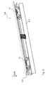
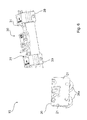
Das Rollenmodul 20 ist hier mit einer Lagervorrichtung 26 ausgestattet. Diese Lagervorrichtung 26 ist hier in Form von zwei Rollen 26a ausgestattet, welche rotierbar an einem Basiskörper des Rollenmoduls 20 gelagert sind. Diese Rollen 26a können nun auf bzw. in einer Rollenlaufbahn 120 eingesetzt werden, wie in der
Wie aus der
Eine weitere Montagevorrichtung 90 ist hier eine Zubehörvorrichtung 40, welche durch eine entsprechende Schnittstelle und ein angebrachtes Zubehörmodul 300 zur Verfügung gestellt ist. Darüber hinaus ist eine Aushebeschutzvorrichtung 60 als Montagevorrichtung 90 vorgesehen, welche einen Aushebeschutz gegen unerwünschtes Verlassen des Rollenwagens 10 der in der Rollenlaufbahn 120 eingesetzten Position zur Verfügung stellt. Weiter ist eine Befestigungsvorrichtung 80 als Glasklemme für eine Montagevorrichtung 90 vorgesehen, um die Schiebetür 110 in klemmender Weise zu befestigen.Another mounting
Allen Montagevorrichtungen ist es gemeinsam, dass sie zumindest ein Montagemittel 92 aufweisen, um eine entsprechende Montagebewegung durchführen zu können. Darüber hinaus ist eine Handhabungsschnittstelle vorgesehen, um genau diese Montagebewegung mit dem Montagemittel auch durchführen zu können.All mounting devices have in common that they have at least one mounting means 92 in order to perform a corresponding assembly movement can. In addition, a handling interface is provided in order to perform precisely this assembly movement with the mounting means also.
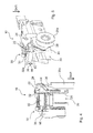
Wie der
In
In
Werden die beiden Bauteile des Grundkörpers 30 und des Rollenmoduls 20 aneinander befestigt, so ergibt sich eine erfindungsgemäße Materialpaarung. Die beiden Materialien, also das erste Material des Rollenmoduls 20 und das zweite Material des Grundkörpers 30 weisen dabei eine schalltechnische Eigenschaft auf, wie sie abstrakt die
Die voranstehende Erläuterung der Ausführungsformen beschreibt die vorliegende Erfindung ausschließlich im Rahmen von Beispielen. Selbstverständlich können einzelne Merkmale der Ausführungsformen, sofern technisch sinnvoll, frei miteinander kombiniert werden, ohne den Rahmen der vorliegenden Erfindung zu verlassen.The above explanation of the embodiments describes the present invention solely by way of example. Of course, individual features of the embodiments, if technically feasible, can be combined freely with one another, without departing from the scope of the present invention.
- 1010
- Rollenwagenroller carriage
- 1212
- erste Seitefirst page
- 1414
- zweite Seitesecond page
- 2020
- Rollenmodulroller module
- 2121
- Übertragungsabschnitttransmission section
- 2222
- zweites Verstellmittelsecond adjustment means
- 2424
- GegenkontaktabschnittMating contact portion
- 2626
- Lagervorrichtungbearing device
- 26a26a
- Rollerole
- 3030
- Grundkörperbody
- 3131
- GegenübertragungsabschnittCountertransference section
- 3232
- erstes Verstellmittelfirst adjustment means
- 32a32a
- VerstellgewindeAdjusting thread
- 3434
- KontaktabschnittContact section
- 3636
- HandhabungsschnittstelleHandling interface
- 3838
- Verstärkungsrippereinforcing rib
- 3939
- Glasklemmeglass clamp
- 4040
- Zubehörvorrichtungaccessory device
- 5050
- Sicherungsvorrichtungsafety device
- 5252
- Anschlagsvorrichtungstop device
- 6060
- AushebeschutzvorrichtungAushebeschutzvorrichtung
- 7070
- Höhenverstellvorrichtungheight adjustment
- 8080
- Befestigungsvorrichtungfastening device
- 9090
- Montagevorrichtungmounter
- 9292
- Montagemittelmounting means
- 9696
- HandhabungsschnittstelleHandling interface
- 96a96a
- FormschlussabschnittForm-fitting section
- 100100
- Schiebetürenanlagesliding system
- 110110
- Schiebetürsliding door
- 120120
- RollenlaufbahnRoller track
- 200200
- Handhabungswerkzeughandling tool
- 210210
- SchnittstellenabschnittInterface section
- 300300
- ZubehörmodulAccessories module
- SKRSKR
- SchwerkraftrichtungThe direction of gravity
- BABA
- Bewegungsachsemotion axis
- II
- erster Schallleitbereichfirst conductive area
- IIII
- zweiter Schallleitbereichsecond conductive area
Claims (14)
Priority Applications (3)
| Application Number | Priority Date | Filing Date | Title |
|---|---|---|---|
| EP14193359.8A EP3020898B1 (en) | 2014-11-14 | 2014-11-14 | Roller carriage for mounting a sliding door |
| CN201510767044.1A CN105604427A (en) | 2014-11-14 | 2015-11-11 | Roller carriage for the reception of sliding door |
| US14/938,645 US9834969B2 (en) | 2014-11-14 | 2015-11-11 | Roller carriage for the reception of a sliding door |
Applications Claiming Priority (1)
| Application Number | Priority Date | Filing Date | Title |
|---|---|---|---|
| EP14193359.8A EP3020898B1 (en) | 2014-11-14 | 2014-11-14 | Roller carriage for mounting a sliding door |
Publications (2)
| Publication Number | Publication Date |
|---|---|
| EP3020898A1 true EP3020898A1 (en) | 2016-05-18 |
| EP3020898B1 EP3020898B1 (en) | 2020-12-30 |
Family
ID=51897194
Family Applications (1)
| Application Number | Title | Priority Date | Filing Date |
|---|---|---|---|
| EP14193359.8A Active EP3020898B1 (en) | 2014-11-14 | 2014-11-14 | Roller carriage for mounting a sliding door |
Country Status (3)
| Country | Link |
|---|---|
| US (1) | US9834969B2 (en) |
| EP (1) | EP3020898B1 (en) |
| CN (1) | CN105604427A (en) |
Cited By (2)
| Publication number | Priority date | Publication date | Assignee | Title |
|---|---|---|---|---|
| US10526840B2 (en) * | 2018-03-23 | 2020-01-07 | Oscar Torrabias Cantal | Perimetrical frame for glass doors |
| CN114575693A (en) * | 2022-03-14 | 2022-06-03 | 广东欧派克家居智能科技有限公司 | Damping pulley mechanism |
Families Citing this family (4)
| Publication number | Priority date | Publication date | Assignee | Title |
|---|---|---|---|---|
| EP3020901B1 (en) * | 2014-11-14 | 2021-11-10 | dormakaba Deutschland GmbH | Roller carriage for mounting a sliding door with at least two mounting devices |
| KR101661080B1 (en) * | 2016-01-11 | 2016-09-28 | 신정철 | A Self-Closing Device for Sliding Door capable of multi-direction rotation |
| KR101718659B1 (en) * | 2016-01-11 | 2017-03-21 | 신정철 | A Self-Closing Device for Sliding Door |
| MX2018008213A (en) * | 2016-09-15 | 2018-12-06 | Goldbrecht Inc | Sliding door and window roller assembly. |
Citations (3)
| Publication number | Priority date | Publication date | Assignee | Title |
|---|---|---|---|---|
| US3107947A (en) * | 1961-11-15 | 1963-10-22 | Flambeau Plastics Corp | Nylon wheel and axle assembly |
| DE4002487A1 (en) * | 1990-01-29 | 1991-08-01 | Geze Gmbh & Co | Running gear for sliding doors, windows - has carrier bolt supported in elastic transverse pivot mounted in carriage |
| WO2010147845A2 (en) * | 2009-06-17 | 2010-12-23 | Hunter Douglas Industries B.V. | Slidable partition suspension systems |
Family Cites Families (18)
| Publication number | Priority date | Publication date | Assignee | Title |
|---|---|---|---|---|
| US2611920A (en) * | 1948-09-14 | 1952-09-30 | Haughton Elevator Company | Track for sliding doors |
| US3837119A (en) * | 1973-05-14 | 1974-09-24 | Ardco Inc | Refrigerator door closure system |
| US5165142A (en) * | 1990-10-04 | 1992-11-24 | Inventio Ag | Runner guide for a sliding elevator door |
| ES2070382T3 (en) * | 1990-10-04 | 1995-06-01 | Inventio Ag | COMBINATION OF GUIDE RAIL AND ROLLER ROLLER, AS COMPONENTS OF AN AUTOMATIC ELEVATOR DOOR. |
| US6381904B1 (en) * | 2000-06-27 | 2002-05-07 | Kohler Co. | Track mounted bath doors with clip anti-derailer |
| US6945364B1 (en) * | 2000-08-25 | 2005-09-20 | Otis Elevator Company | Elevator roller guide and rail assembly |
| US6540068B1 (en) * | 2000-11-10 | 2003-04-01 | Otis Elevator Company | Rim assembly for a roller assembly for use with cargo mover systems |
| CN2672237Y (en) * | 2003-09-22 | 2005-01-19 | 夏仕成 | Rotary shaft sliding type slide wheel of door and window |
| DE102004050596B4 (en) * | 2004-10-15 | 2016-01-28 | Dorma Deutschland Gmbh | Clamping connection between the clamping shoe of a roller carriage and a sliding sash |
| CN2748610Y (en) * | 2004-11-18 | 2005-12-28 | 夏仕成 | Bridge-shaped support type pulley for plastic-steel door and window |
| US20060225360A1 (en) * | 2005-03-14 | 2006-10-12 | Gray Bill M | Rolling door retainer |
| DE102006021443A1 (en) * | 2006-05-09 | 2007-11-29 | Schaeffler Kg | Running device of a horizontally movable sliding door |
| CN201486329U (en) * | 2009-06-03 | 2010-05-26 | 林克俭 | Bridge cutoff aluminum alloy pulley |
| US8881460B2 (en) * | 2009-06-04 | 2014-11-11 | Groupe Vfg Inc. | Sliding door system for glass doors |
| CH701232A1 (en) * | 2009-06-09 | 2010-12-15 | Planet Gdz Ag | Door seal system. |
| US8955195B2 (en) * | 2012-11-25 | 2015-02-17 | Door & Window Hardware Co. | Clamping-sliding assembly for a single-track-suspension sliding door |
| CN203430262U (en) * | 2013-07-26 | 2014-02-12 | 周裕佳 | Adjustable suspension clamp structure |
| CN203879174U (en) * | 2013-12-11 | 2014-10-15 | 广东坚朗五金制品股份有限公司 | Pulley device for sliding door |
-
2014
- 2014-11-14 EP EP14193359.8A patent/EP3020898B1/en active Active
-
2015
- 2015-11-11 CN CN201510767044.1A patent/CN105604427A/en active Pending
- 2015-11-11 US US14/938,645 patent/US9834969B2/en active Active
Patent Citations (3)
| Publication number | Priority date | Publication date | Assignee | Title |
|---|---|---|---|---|
| US3107947A (en) * | 1961-11-15 | 1963-10-22 | Flambeau Plastics Corp | Nylon wheel and axle assembly |
| DE4002487A1 (en) * | 1990-01-29 | 1991-08-01 | Geze Gmbh & Co | Running gear for sliding doors, windows - has carrier bolt supported in elastic transverse pivot mounted in carriage |
| WO2010147845A2 (en) * | 2009-06-17 | 2010-12-23 | Hunter Douglas Industries B.V. | Slidable partition suspension systems |
Cited By (2)
| Publication number | Priority date | Publication date | Assignee | Title |
|---|---|---|---|---|
| US10526840B2 (en) * | 2018-03-23 | 2020-01-07 | Oscar Torrabias Cantal | Perimetrical frame for glass doors |
| CN114575693A (en) * | 2022-03-14 | 2022-06-03 | 广东欧派克家居智能科技有限公司 | Damping pulley mechanism |
Also Published As
| Publication number | Publication date |
|---|---|
| US20160138313A1 (en) | 2016-05-19 |
| EP3020898B1 (en) | 2020-12-30 |
| US9834969B2 (en) | 2017-12-05 |
| CN105604427A (en) | 2016-05-25 |
Similar Documents
| Publication | Publication Date | Title |
|---|---|---|
| EP3020898B1 (en) | Roller carriage for mounting a sliding door | |
| DE102007013446B4 (en) | Electric actuator | |
| DE202013102583U1 (en) | Door assembly | |
| AT518136B1 (en) | drawer | |
| DE102008024314A1 (en) | Conveyor belt has belt body, at which two guide rollers are held, and endless belt is guided through guide rollers, where guide rollers have fine adjustment with adjusting screw | |
| DE102016119875A1 (en) | Rebound suppression system for a sliding door | |
| EP1975355A2 (en) | Retrofit kit for a sliding door and sliding door installation | |
| DE112013002426T5 (en) | Motion control device | |
| DE102011111297B4 (en) | Device for holding guide rails for passenger and goods lifts | |
| EP3201412A1 (en) | Guiding device for guiding a sliding door, and cabinet-type piece of furniture | |
| DE60314498T2 (en) | DRIVE MECHANISM FOR A BODY ON RAILS | |
| EP2677200A1 (en) | Linear drive | |
| EP2009214B1 (en) | Connecting piece for connecting two guide rails and guide rail | |
| DE102013106134B4 (en) | Protective cover for a processing machine and method of manufacturing the protective cover | |
| DE2702731C2 (en) | Door stops for car doors | |
| DE10361548A1 (en) | Hinge plate for heavy door, has supporting parts made up of rugged plastic such as Teflon, and placed between supporting sections, into which set screw is screwed, and ball made up of steel and arranged between supporting parts | |
| DE202015100603U1 (en) | telescopic rail | |
| EP3625420B1 (en) | Furniture and method for assembling a slide element on a furniture carcass | |
| EP0079541B1 (en) | Device comprising a frame section | |
| DE102005023816B4 (en) | Electric window device for a motor vehicle | |
| DE102009043897B4 (en) | Ball screw with externally rotating rolling elements with a noise suppression arrangement | |
| AT509924B1 (en) | ARRANGEMENT FOR ONE DRAWER DRAWING AT LEAST TWO TELESCOPIC APPEARED RAILS | |
| DE20107275U1 (en) | Guide device for sliding door elements | |
| EP2549040B2 (en) | Combination comprising of support structure and carriage for a sliding door | |
| DE202006003029U1 (en) | Cover for linear guide, has rigid cover profile to cover guide rail of linear guide, and guiding part movable through guiding carriage of linear guide and including continuous guiding channel for feed through of cover profile |
Legal Events
| Date | Code | Title | Description |
|---|---|---|---|
| PUAI | Public reference made under article 153(3) epc to a published international application that has entered the european phase |
Free format text: ORIGINAL CODE: 0009012 |
|
| AK | Designated contracting states |
Kind code of ref document: A1 Designated state(s): AL AT BE BG CH CY CZ DE DK EE ES FI FR GB GR HR HU IE IS IT LI LT LU LV MC MK MT NL NO PL PT RO RS SE SI SK SM TR |
|
| AX | Request for extension of the european patent |
Extension state: BA ME |
|
| STAA | Information on the status of an ep patent application or granted ep patent |
Free format text: STATUS: REQUEST FOR EXAMINATION WAS MADE |
|
| 17P | Request for examination filed |
Effective date: 20161028 |
|
| RBV | Designated contracting states (corrected) |
Designated state(s): AL AT BE BG CH CY CZ DE DK EE ES FI FR GB GR HR HU IE IS IT LI LT LU LV MC MK MT NL NO PL PT RO RS SE SI SK SM TR |
|
| RAP1 | Party data changed (applicant data changed or rights of an application transferred) |
Owner name: DORMAKABA DEUTSCHLAND GMBH |
|
| STAA | Information on the status of an ep patent application or granted ep patent |
Free format text: STATUS: EXAMINATION IS IN PROGRESS |
|
| 17Q | First examination report despatched |
Effective date: 20171012 |
|
| GRAP | Despatch of communication of intention to grant a patent |
Free format text: ORIGINAL CODE: EPIDOSNIGR1 |
|
| STAA | Information on the status of an ep patent application or granted ep patent |
Free format text: STATUS: GRANT OF PATENT IS INTENDED |
|
| INTG | Intention to grant announced |
Effective date: 20200728 |
|
| GRAS | Grant fee paid |
Free format text: ORIGINAL CODE: EPIDOSNIGR3 |
|
| GRAA | (expected) grant |
Free format text: ORIGINAL CODE: 0009210 |
|
| STAA | Information on the status of an ep patent application or granted ep patent |
Free format text: STATUS: THE PATENT HAS BEEN GRANTED |
|
| AK | Designated contracting states |
Kind code of ref document: B1 Designated state(s): AL AT BE BG CH CY CZ DE DK EE ES FI FR GB GR HR HU IE IS IT LI LT LU LV MC MK MT NL NO PL PT RO RS SE SI SK SM TR |
|
| REG | Reference to a national code |
Ref country code: GB Ref legal event code: FG4D Free format text: NOT ENGLISH |
|
| REG | Reference to a national code |
Ref country code: AT Ref legal event code: REF Ref document number: 1350076 Country of ref document: AT Kind code of ref document: T Effective date: 20210115 |
|
| REG | Reference to a national code |
Ref country code: DE Ref legal event code: R096 Ref document number: 502014015148 Country of ref document: DE |
|
| REG | Reference to a national code |
Ref country code: IE Ref legal event code: FG4D Free format text: LANGUAGE OF EP DOCUMENT: GERMAN |
|
| REG | Reference to a national code |
Ref country code: CH Ref legal event code: NV Representative=s name: FREI PATENTANWALTSBUERO AG, CH |
|
| PG25 | Lapsed in a contracting state [announced via postgrant information from national office to epo] |
Ref country code: RS Free format text: LAPSE BECAUSE OF FAILURE TO SUBMIT A TRANSLATION OF THE DESCRIPTION OR TO PAY THE FEE WITHIN THE PRESCRIBED TIME-LIMIT Effective date: 20201230 Ref country code: FI Free format text: LAPSE BECAUSE OF FAILURE TO SUBMIT A TRANSLATION OF THE DESCRIPTION OR TO PAY THE FEE WITHIN THE PRESCRIBED TIME-LIMIT Effective date: 20201230 Ref country code: NO Free format text: LAPSE BECAUSE OF FAILURE TO SUBMIT A TRANSLATION OF THE DESCRIPTION OR TO PAY THE FEE WITHIN THE PRESCRIBED TIME-LIMIT Effective date: 20210330 Ref country code: GR Free format text: LAPSE BECAUSE OF FAILURE TO SUBMIT A TRANSLATION OF THE DESCRIPTION OR TO PAY THE FEE WITHIN THE PRESCRIBED TIME-LIMIT Effective date: 20210331 |
|
| PG25 | Lapsed in a contracting state [announced via postgrant information from national office to epo] |
Ref country code: SE Free format text: LAPSE BECAUSE OF FAILURE TO SUBMIT A TRANSLATION OF THE DESCRIPTION OR TO PAY THE FEE WITHIN THE PRESCRIBED TIME-LIMIT Effective date: 20201230 Ref country code: LV Free format text: LAPSE BECAUSE OF FAILURE TO SUBMIT A TRANSLATION OF THE DESCRIPTION OR TO PAY THE FEE WITHIN THE PRESCRIBED TIME-LIMIT Effective date: 20201230 Ref country code: BG Free format text: LAPSE BECAUSE OF FAILURE TO SUBMIT A TRANSLATION OF THE DESCRIPTION OR TO PAY THE FEE WITHIN THE PRESCRIBED TIME-LIMIT Effective date: 20210330 |
|
| REG | Reference to a national code |
Ref country code: NL Ref legal event code: MP Effective date: 20201230 |
|
| PG25 | Lapsed in a contracting state [announced via postgrant information from national office to epo] |
Ref country code: HR Free format text: LAPSE BECAUSE OF FAILURE TO SUBMIT A TRANSLATION OF THE DESCRIPTION OR TO PAY THE FEE WITHIN THE PRESCRIBED TIME-LIMIT Effective date: 20201230 |
|
| REG | Reference to a national code |
Ref country code: LT Ref legal event code: MG9D |
|
| PG25 | Lapsed in a contracting state [announced via postgrant information from national office to epo] |
Ref country code: SK Free format text: LAPSE BECAUSE OF FAILURE TO SUBMIT A TRANSLATION OF THE DESCRIPTION OR TO PAY THE FEE WITHIN THE PRESCRIBED TIME-LIMIT Effective date: 20201230 Ref country code: RO Free format text: LAPSE BECAUSE OF FAILURE TO SUBMIT A TRANSLATION OF THE DESCRIPTION OR TO PAY THE FEE WITHIN THE PRESCRIBED TIME-LIMIT Effective date: 20201230 Ref country code: PT Free format text: LAPSE BECAUSE OF FAILURE TO SUBMIT A TRANSLATION OF THE DESCRIPTION OR TO PAY THE FEE WITHIN THE PRESCRIBED TIME-LIMIT Effective date: 20210430 Ref country code: LT Free format text: LAPSE BECAUSE OF FAILURE TO SUBMIT A TRANSLATION OF THE DESCRIPTION OR TO PAY THE FEE WITHIN THE PRESCRIBED TIME-LIMIT Effective date: 20201230 Ref country code: CZ Free format text: LAPSE BECAUSE OF FAILURE TO SUBMIT A TRANSLATION OF THE DESCRIPTION OR TO PAY THE FEE WITHIN THE PRESCRIBED TIME-LIMIT Effective date: 20201230 Ref country code: EE Free format text: LAPSE BECAUSE OF FAILURE TO SUBMIT A TRANSLATION OF THE DESCRIPTION OR TO PAY THE FEE WITHIN THE PRESCRIBED TIME-LIMIT Effective date: 20201230 Ref country code: NL Free format text: LAPSE BECAUSE OF FAILURE TO SUBMIT A TRANSLATION OF THE DESCRIPTION OR TO PAY THE FEE WITHIN THE PRESCRIBED TIME-LIMIT Effective date: 20201230 |
|
| PG25 | Lapsed in a contracting state [announced via postgrant information from national office to epo] |
Ref country code: PL Free format text: LAPSE BECAUSE OF FAILURE TO SUBMIT A TRANSLATION OF THE DESCRIPTION OR TO PAY THE FEE WITHIN THE PRESCRIBED TIME-LIMIT Effective date: 20201230 |
|
| PG25 | Lapsed in a contracting state [announced via postgrant information from national office to epo] |
Ref country code: IS Free format text: LAPSE BECAUSE OF FAILURE TO SUBMIT A TRANSLATION OF THE DESCRIPTION OR TO PAY THE FEE WITHIN THE PRESCRIBED TIME-LIMIT Effective date: 20210430 |
|
| REG | Reference to a national code |
Ref country code: DE Ref legal event code: R097 Ref document number: 502014015148 Country of ref document: DE |
|
| PG25 | Lapsed in a contracting state [announced via postgrant information from national office to epo] |
Ref country code: IT Free format text: LAPSE BECAUSE OF FAILURE TO SUBMIT A TRANSLATION OF THE DESCRIPTION OR TO PAY THE FEE WITHIN THE PRESCRIBED TIME-LIMIT Effective date: 20201230 Ref country code: AL Free format text: LAPSE BECAUSE OF FAILURE TO SUBMIT A TRANSLATION OF THE DESCRIPTION OR TO PAY THE FEE WITHIN THE PRESCRIBED TIME-LIMIT Effective date: 20201230 |
|
| PLBE | No opposition filed within time limit |
Free format text: ORIGINAL CODE: 0009261 |
|
| STAA | Information on the status of an ep patent application or granted ep patent |
Free format text: STATUS: NO OPPOSITION FILED WITHIN TIME LIMIT |
|
| PG25 | Lapsed in a contracting state [announced via postgrant information from national office to epo] |
Ref country code: DK Free format text: LAPSE BECAUSE OF FAILURE TO SUBMIT A TRANSLATION OF THE DESCRIPTION OR TO PAY THE FEE WITHIN THE PRESCRIBED TIME-LIMIT Effective date: 20201230 Ref country code: ES Free format text: LAPSE BECAUSE OF FAILURE TO SUBMIT A TRANSLATION OF THE DESCRIPTION OR TO PAY THE FEE WITHIN THE PRESCRIBED TIME-LIMIT Effective date: 20201230 |
|
| 26N | No opposition filed |
Effective date: 20211001 |
|
| REG | Reference to a national code |
Ref country code: DE Ref legal event code: R081 Ref document number: 502014015148 Country of ref document: DE Owner name: DORMA-GLAS GMBH, DE Free format text: FORMER OWNER: DORMAKABA DEUTSCHLAND GMBH, 58256 ENNEPETAL, DE |
|
| PG25 | Lapsed in a contracting state [announced via postgrant information from national office to epo] |
Ref country code: SI Free format text: LAPSE BECAUSE OF FAILURE TO SUBMIT A TRANSLATION OF THE DESCRIPTION OR TO PAY THE FEE WITHIN THE PRESCRIBED TIME-LIMIT Effective date: 20201230 |
|
| REG | Reference to a national code |
Ref country code: AT Ref legal event code: PC Ref document number: 1350076 Country of ref document: AT Kind code of ref document: T Owner name: DORMA-GLAS GMBH, DE Effective date: 20220216 |
|
| PG25 | Lapsed in a contracting state [announced via postgrant information from national office to epo] |
Ref country code: IS Free format text: LAPSE BECAUSE OF FAILURE TO SUBMIT A TRANSLATION OF THE DESCRIPTION OR TO PAY THE FEE WITHIN THE PRESCRIBED TIME-LIMIT Effective date: 20210430 |
|
| PG25 | Lapsed in a contracting state [announced via postgrant information from national office to epo] |
Ref country code: MC Free format text: LAPSE BECAUSE OF FAILURE TO SUBMIT A TRANSLATION OF THE DESCRIPTION OR TO PAY THE FEE WITHIN THE PRESCRIBED TIME-LIMIT Effective date: 20201230 |
|
| GBPC | Gb: european patent ceased through non-payment of renewal fee |
Effective date: 20211114 |
|
| PG25 | Lapsed in a contracting state [announced via postgrant information from national office to epo] |
Ref country code: LU Free format text: LAPSE BECAUSE OF NON-PAYMENT OF DUE FEES Effective date: 20211114 Ref country code: BE Free format text: LAPSE BECAUSE OF NON-PAYMENT OF DUE FEES Effective date: 20211130 |
|
| REG | Reference to a national code |
Ref country code: BE Ref legal event code: MM Effective date: 20211130 |
|
| PG25 | Lapsed in a contracting state [announced via postgrant information from national office to epo] |
Ref country code: IE Free format text: LAPSE BECAUSE OF NON-PAYMENT OF DUE FEES Effective date: 20211114 Ref country code: GB Free format text: LAPSE BECAUSE OF NON-PAYMENT OF DUE FEES Effective date: 20211114 |
|
| PG25 | Lapsed in a contracting state [announced via postgrant information from national office to epo] |
Ref country code: FR Free format text: LAPSE BECAUSE OF NON-PAYMENT OF DUE FEES Effective date: 20211130 |
|
| PG25 | Lapsed in a contracting state [announced via postgrant information from national office to epo] |
Ref country code: HU Free format text: LAPSE BECAUSE OF FAILURE TO SUBMIT A TRANSLATION OF THE DESCRIPTION OR TO PAY THE FEE WITHIN THE PRESCRIBED TIME-LIMIT; INVALID AB INITIO Effective date: 20141114 |
|
| PG25 | Lapsed in a contracting state [announced via postgrant information from national office to epo] |
Ref country code: CY Free format text: LAPSE BECAUSE OF FAILURE TO SUBMIT A TRANSLATION OF THE DESCRIPTION OR TO PAY THE FEE WITHIN THE PRESCRIBED TIME-LIMIT Effective date: 20201230 |
|
| PG25 | Lapsed in a contracting state [announced via postgrant information from national office to epo] |
Ref country code: SM Free format text: LAPSE BECAUSE OF FAILURE TO SUBMIT A TRANSLATION OF THE DESCRIPTION OR TO PAY THE FEE WITHIN THE PRESCRIBED TIME-LIMIT Effective date: 20201230 |
|
| PGFP | Annual fee paid to national office [announced via postgrant information from national office to epo] |
Ref country code: DE Payment date: 20231121 Year of fee payment: 10 Ref country code: CH Payment date: 20231201 Year of fee payment: 10 Ref country code: AT Payment date: 20231121 Year of fee payment: 10 |