EP3020545B1 - Vorrichtung zur herstellung von kunststoffbeuteln - Google Patents
Vorrichtung zur herstellung von kunststoffbeuteln Download PDFInfo
- Publication number
- EP3020545B1 EP3020545B1 EP14192980.2A EP14192980A EP3020545B1 EP 3020545 B1 EP3020545 B1 EP 3020545B1 EP 14192980 A EP14192980 A EP 14192980A EP 3020545 B1 EP3020545 B1 EP 3020545B1
- Authority
- EP
- European Patent Office
- Prior art keywords
- web
- webs
- fastener
- panel
- side gusset
- Prior art date
- Legal status (The legal status is an assumption and is not a legal conclusion. Google has not performed a legal analysis and makes no representation as to the accuracy of the status listed.)
- Not-in-force
Links
- 239000004033 plastic Substances 0.000 title claims description 48
- 239000000463 material Substances 0.000 claims description 474
- 239000002985 plastic film Substances 0.000 description 3
- 229920006255 plastic film Polymers 0.000 description 3
- 239000000565 sealant Substances 0.000 description 3
- 238000006243 chemical reaction Methods 0.000 description 2
Images


Classifications
-
- B—PERFORMING OPERATIONS; TRANSPORTING
- B31—MAKING ARTICLES OF PAPER, CARDBOARD OR MATERIAL WORKED IN A MANNER ANALOGOUS TO PAPER; WORKING PAPER, CARDBOARD OR MATERIAL WORKED IN A MANNER ANALOGOUS TO PAPER
- B31B—MAKING CONTAINERS OF PAPER, CARDBOARD OR MATERIAL WORKED IN A MANNER ANALOGOUS TO PAPER
- B31B70/00—Making flexible containers, e.g. envelopes or bags
- B31B70/74—Auxiliary operations
- B31B70/81—Forming or attaching accessories, e.g. opening devices, closures or tear strings
- B31B70/813—Applying closures
- B31B70/8131—Making bags having interengaging closure elements
- B31B70/8132—Applying the closure elements in the machine direction
-
- B—PERFORMING OPERATIONS; TRANSPORTING
- B29—WORKING OF PLASTICS; WORKING OF SUBSTANCES IN A PLASTIC STATE IN GENERAL
- B29C—SHAPING OR JOINING OF PLASTICS; SHAPING OF MATERIAL IN A PLASTIC STATE, NOT OTHERWISE PROVIDED FOR; AFTER-TREATMENT OF THE SHAPED PRODUCTS, e.g. REPAIRING
- B29C65/00—Joining or sealing of preformed parts, e.g. welding of plastics materials; Apparatus therefor
- B29C65/02—Joining or sealing of preformed parts, e.g. welding of plastics materials; Apparatus therefor by heating, with or without pressure
- B29C65/18—Joining or sealing of preformed parts, e.g. welding of plastics materials; Apparatus therefor by heating, with or without pressure using heated tools
-
- B—PERFORMING OPERATIONS; TRANSPORTING
- B29—WORKING OF PLASTICS; WORKING OF SUBSTANCES IN A PLASTIC STATE IN GENERAL
- B29C—SHAPING OR JOINING OF PLASTICS; SHAPING OF MATERIAL IN A PLASTIC STATE, NOT OTHERWISE PROVIDED FOR; AFTER-TREATMENT OF THE SHAPED PRODUCTS, e.g. REPAIRING
- B29C65/00—Joining or sealing of preformed parts, e.g. welding of plastics materials; Apparatus therefor
- B29C65/78—Means for handling the parts to be joined, e.g. for making containers or hollow articles, e.g. means for handling sheets, plates, web-like materials, tubular articles, hollow articles or elements to be joined therewith; Means for discharging the joined articles from the joining apparatus
- B29C65/7841—Holding or clamping means for handling purposes
-
- B—PERFORMING OPERATIONS; TRANSPORTING
- B29—WORKING OF PLASTICS; WORKING OF SUBSTANCES IN A PLASTIC STATE IN GENERAL
- B29C—SHAPING OR JOINING OF PLASTICS; SHAPING OF MATERIAL IN A PLASTIC STATE, NOT OTHERWISE PROVIDED FOR; AFTER-TREATMENT OF THE SHAPED PRODUCTS, e.g. REPAIRING
- B29C66/00—General aspects of processes or apparatus for joining preformed parts
- B29C66/01—General aspects dealing with the joint area or with the area to be joined
- B29C66/05—Particular design of joint configurations
- B29C66/10—Particular design of joint configurations particular design of the joint cross-sections
- B29C66/11—Joint cross-sections comprising a single joint-segment, i.e. one of the parts to be joined comprising a single joint-segment in the joint cross-section
- B29C66/112—Single lapped joints
- B29C66/1122—Single lap to lap joints, i.e. overlap joints
-
- B—PERFORMING OPERATIONS; TRANSPORTING
- B29—WORKING OF PLASTICS; WORKING OF SUBSTANCES IN A PLASTIC STATE IN GENERAL
- B29C—SHAPING OR JOINING OF PLASTICS; SHAPING OF MATERIAL IN A PLASTIC STATE, NOT OTHERWISE PROVIDED FOR; AFTER-TREATMENT OF THE SHAPED PRODUCTS, e.g. REPAIRING
- B29C66/00—General aspects of processes or apparatus for joining preformed parts
- B29C66/40—General aspects of joining substantially flat articles, e.g. plates, sheets or web-like materials; Making flat seams in tubular or hollow articles; Joining single elements to substantially flat surfaces
- B29C66/47—Joining single elements to sheets, plates or other substantially flat surfaces
- B29C66/474—Joining single elements to sheets, plates or other substantially flat surfaces said single elements being substantially non-flat
-
- B—PERFORMING OPERATIONS; TRANSPORTING
- B29—WORKING OF PLASTICS; WORKING OF SUBSTANCES IN A PLASTIC STATE IN GENERAL
- B29C—SHAPING OR JOINING OF PLASTICS; SHAPING OF MATERIAL IN A PLASTIC STATE, NOT OTHERWISE PROVIDED FOR; AFTER-TREATMENT OF THE SHAPED PRODUCTS, e.g. REPAIRING
- B29C66/00—General aspects of processes or apparatus for joining preformed parts
- B29C66/80—General aspects of machine operations or constructions and parts thereof
- B29C66/81—General aspects of the pressing elements, i.e. the elements applying pressure on the parts to be joined in the area to be joined, e.g. the welding jaws or clamps
- B29C66/814—General aspects of the pressing elements, i.e. the elements applying pressure on the parts to be joined in the area to be joined, e.g. the welding jaws or clamps characterised by the design of the pressing elements, e.g. of the welding jaws or clamps
- B29C66/8141—General aspects of the pressing elements, i.e. the elements applying pressure on the parts to be joined in the area to be joined, e.g. the welding jaws or clamps characterised by the design of the pressing elements, e.g. of the welding jaws or clamps characterised by the surface geometry of the part of the pressing elements, e.g. welding jaws or clamps, coming into contact with the parts to be joined
- B29C66/81431—General aspects of the pressing elements, i.e. the elements applying pressure on the parts to be joined in the area to be joined, e.g. the welding jaws or clamps characterised by the design of the pressing elements, e.g. of the welding jaws or clamps characterised by the surface geometry of the part of the pressing elements, e.g. welding jaws or clamps, coming into contact with the parts to be joined comprising a single cavity, e.g. a groove
-
- B—PERFORMING OPERATIONS; TRANSPORTING
- B29—WORKING OF PLASTICS; WORKING OF SUBSTANCES IN A PLASTIC STATE IN GENERAL
- B29C—SHAPING OR JOINING OF PLASTICS; SHAPING OF MATERIAL IN A PLASTIC STATE, NOT OTHERWISE PROVIDED FOR; AFTER-TREATMENT OF THE SHAPED PRODUCTS, e.g. REPAIRING
- B29C66/00—General aspects of processes or apparatus for joining preformed parts
- B29C66/80—General aspects of machine operations or constructions and parts thereof
- B29C66/83—General aspects of machine operations or constructions and parts thereof characterised by the movement of the joining or pressing tools
- B29C66/832—Reciprocating joining or pressing tools
- B29C66/8322—Joining or pressing tools reciprocating along one axis
-
- B—PERFORMING OPERATIONS; TRANSPORTING
- B29—WORKING OF PLASTICS; WORKING OF SUBSTANCES IN A PLASTIC STATE IN GENERAL
- B29C—SHAPING OR JOINING OF PLASTICS; SHAPING OF MATERIAL IN A PLASTIC STATE, NOT OTHERWISE PROVIDED FOR; AFTER-TREATMENT OF THE SHAPED PRODUCTS, e.g. REPAIRING
- B29C66/00—General aspects of processes or apparatus for joining preformed parts
- B29C66/80—General aspects of machine operations or constructions and parts thereof
- B29C66/84—Specific machine types or machines suitable for specific applications
- B29C66/851—Bag or container making machines
- B29C66/8511—Bag making machines
-
- B—PERFORMING OPERATIONS; TRANSPORTING
- B29—WORKING OF PLASTICS; WORKING OF SUBSTANCES IN A PLASTIC STATE IN GENERAL
- B29L—INDEXING SCHEME ASSOCIATED WITH SUBCLASS B29C, RELATING TO PARTICULAR ARTICLES
- B29L2005/00—Elements of slide fasteners
-
- B—PERFORMING OPERATIONS; TRANSPORTING
- B29—WORKING OF PLASTICS; WORKING OF SUBSTANCES IN A PLASTIC STATE IN GENERAL
- B29L—INDEXING SCHEME ASSOCIATED WITH SUBCLASS B29C, RELATING TO PARTICULAR ARTICLES
- B29L2031/00—Other particular articles
- B29L2031/712—Containers; Packaging elements or accessories, Packages
- B29L2031/7128—Bags, sacks, sachets
-
- B—PERFORMING OPERATIONS; TRANSPORTING
- B31—MAKING ARTICLES OF PAPER, CARDBOARD OR MATERIAL WORKED IN A MANNER ANALOGOUS TO PAPER; WORKING PAPER, CARDBOARD OR MATERIAL WORKED IN A MANNER ANALOGOUS TO PAPER
- B31B—MAKING CONTAINERS OF PAPER, CARDBOARD OR MATERIAL WORKED IN A MANNER ANALOGOUS TO PAPER
- B31B2155/00—Flexible containers made from webs
- B31B2155/001—Flexible containers made from webs by folding webs longitudinally
- B31B2155/0012—Flexible containers made from webs by folding webs longitudinally having their openings facing in the direction of movement
-
- B—PERFORMING OPERATIONS; TRANSPORTING
- B31—MAKING ARTICLES OF PAPER, CARDBOARD OR MATERIAL WORKED IN A MANNER ANALOGOUS TO PAPER; WORKING PAPER, CARDBOARD OR MATERIAL WORKED IN A MANNER ANALOGOUS TO PAPER
- B31B—MAKING CONTAINERS OF PAPER, CARDBOARD OR MATERIAL WORKED IN A MANNER ANALOGOUS TO PAPER
- B31B2160/00—Shape of flexible containers
- B31B2160/10—Shape of flexible containers rectangular and flat, i.e. without structural provision for thickness of contents
-
- B—PERFORMING OPERATIONS; TRANSPORTING
- B31—MAKING ARTICLES OF PAPER, CARDBOARD OR MATERIAL WORKED IN A MANNER ANALOGOUS TO PAPER; WORKING PAPER, CARDBOARD OR MATERIAL WORKED IN A MANNER ANALOGOUS TO PAPER
- B31B—MAKING CONTAINERS OF PAPER, CARDBOARD OR MATERIAL WORKED IN A MANNER ANALOGOUS TO PAPER
- B31B2170/00—Construction of flexible containers
- B31B2170/20—Construction of flexible containers having multi-layered walls, e.g. laminated or lined
-
- B—PERFORMING OPERATIONS; TRANSPORTING
- B31—MAKING ARTICLES OF PAPER, CARDBOARD OR MATERIAL WORKED IN A MANNER ANALOGOUS TO PAPER; WORKING PAPER, CARDBOARD OR MATERIAL WORKED IN A MANNER ANALOGOUS TO PAPER
- B31B—MAKING CONTAINERS OF PAPER, CARDBOARD OR MATERIAL WORKED IN A MANNER ANALOGOUS TO PAPER
- B31B70/00—Making flexible containers, e.g. envelopes or bags
- B31B70/60—Uniting opposed surfaces or edges; Taping
- B31B70/61—Uniting opposed surfaces or edges; Taping by applying or securing strips or tape
-
- B—PERFORMING OPERATIONS; TRANSPORTING
- B31—MAKING ARTICLES OF PAPER, CARDBOARD OR MATERIAL WORKED IN A MANNER ANALOGOUS TO PAPER; WORKING PAPER, CARDBOARD OR MATERIAL WORKED IN A MANNER ANALOGOUS TO PAPER
- B31B—MAKING CONTAINERS OF PAPER, CARDBOARD OR MATERIAL WORKED IN A MANNER ANALOGOUS TO PAPER
- B31B70/00—Making flexible containers, e.g. envelopes or bags
- B31B70/74—Auxiliary operations
- B31B70/81—Forming or attaching accessories, e.g. opening devices, closures or tear strings
- B31B70/812—Applying patches, strips or strings on sheets or webs
- B31B70/8123—Applying strips
-
- B—PERFORMING OPERATIONS; TRANSPORTING
- B31—MAKING ARTICLES OF PAPER, CARDBOARD OR MATERIAL WORKED IN A MANNER ANALOGOUS TO PAPER; WORKING PAPER, CARDBOARD OR MATERIAL WORKED IN A MANNER ANALOGOUS TO PAPER
- B31B—MAKING CONTAINERS OF PAPER, CARDBOARD OR MATERIAL WORKED IN A MANNER ANALOGOUS TO PAPER
- B31B70/00—Making flexible containers, e.g. envelopes or bags
- B31B70/74—Auxiliary operations
- B31B70/81—Forming or attaching accessories, e.g. opening devices, closures or tear strings
- B31B70/813—Applying closures
- B31B70/8131—Making bags having interengaging closure elements
- B31B70/8133—Applying the closure elements in the cross direction
Definitions
- the invention relates to an apparatus for successively making plastic bags each of which includes a panel portion, side gusset portions and a fastener portion.
- Japanese Patent Publication No. 5,439,622 and EP 2829391 A1 disclose a bag making apparatus for making a bag with fastener material.
- a moving direction conversion device for the fastener material is presented, where first and second fastener materials travel in a first direction and the traveling direction can be changed to a second direction.
- the moving direction conversion device comprises a pair of turn bars which are arranged such that first and second fastener materials travel in a first direction and then engage with the turn bars. After engagement, the first and second fastener materials are inserted between the respective turn bars such that the fastener materials are reversed and the traveling direction is changed to a second direction.
- Japanese Patent Publication No. 3,655,627 discloses an apparatus for successively making plastic bags each of which includes a panel portion and side gusset portions.
- first and second webs of panel material are superposed with each other and fed longitudinally thereof.
- a web of side gusset material is folded into halves and supplied to the first web of panel material to extend widthwise of the first web of panel material before the first and second webs of panel material are superposed with each other.
- the web of side gusset material is crosscut into a length corresponding to the width of the first and second webs of panel material.
- the web of side gusset material is then interposed between the first and second webs of panel material after the first and second webs of panel material are superposed with each other.
- the apparatus includes a longitudinal seal device by which the first and second webs of panel material are heat sealed with each other longitudinally thereof after being superposed with each other.
- the apparatus further includes a cross seal device by which the first and second webs of panel material and the web of side gusset material are heat sealed with each other widthwise of the first and second webs of panel material after the first and second webs of panel material are superposed with each other.
- the apparatus further includes a cutter by which the first and second webs of panel material are crosscut widthwise thereof after being heat sealed.
- the panel portion is formed of the first and second webs of panel material.
- the side gusset portion is formed of the web of side gusset material.
- Japanese Laid-Open Patent Publication No. 347,788 of 2002 and EP 1247747 A2 disclose a plastic bag including not only the panel portion and the side gusset portions but also a fastener portion.
- the panel portion is formed of first and second sheets of panel material.
- the side gusset portion is formed of a sheet of side gusset material.
- the fastener portion extends along the top edge of plastic bag.
- the fastener portion has a specific structure, in which a first body of fastener material is joined to the first sheet of panel material while a second body of fastener material is joined to the second sheet of panel material within the plastic bag.
- a third body of fastener material is joined to the sheet of side gusset material within the plastic bag, the fastener portion being formed of the first, second and third bodies of fastener material.
- the first and second bodies of fastener material are meshing engaged with each other and with the third body of fastener material.
- the plastic bag can therefore be closed by the first, second and third bodies of fastener material.
- the first, second and third bodies of fastener material comprise parts of hook and loop touch fastener portion.
- the plastic bag would be used for various purposes to be high in utility, regardless of a problem of airtightness of hook and loop touch fastener portion.
- the object of the invention is an apparatus for successively making plastic bags each of which includes a panel portion, side gusset portion and a fastener portion according to claim 1.
- first, second and third bodies of fastener material comprise parts of hook and loop touch fastener portion.
- the web of side gusset material is crosscut or torn off into a length corresponding to the width of the first and second webs of panel material after being folded into halves and after or before being supplied to the first web of panel material.
- the third body of fastener material is crosscut or torn off into the length corresponding to the width of the web of side gusset material after or before being supplied to the web of side gusset material.
- the first and second webs of panel material are fed in a state of being superposed with each other.
- the first and second webs of panel material are then separated and spaced from each other.
- the web of side gusset material is supplied to the first web of panel material after the first and second webs of panel material are spaced from each other.
- the first and second webs of panel material are then superposed with each other again so that the web of side gusset material is interposed between the first and second webs of panel material while the third body of fastener material is interposed between the first and second bodies of fastener material.
- the first and second bodies of fastener material are interposed between the first and second webs of panel material before the first and second webs of panel material are separated from each other, the first body of fastener material being joined to the first web of panel material, the second body of fastener material being joined to the second web of panel material.
- the fastener material joining device comprises a fastener material seal device by which the first body of fastener material is heat sealed with the first web of panel material to be joined thereto while the second body of fastener material is heat sealed with the second web of panel material to be joined thereto.
- the additional joining device comprises an additional seal device by which the third body of fastener material is heat sealed with the web of side gusset material to be joined thereto.
- the apparatus further includes a longitudinal seal device by which the first and second webs of panel material are heat sealed with each other longitudinally thereof after being superposed with each other.
- the apparatus further includes a cross seal device by which the first and second webs of panel material and the web of side gusset material are heat sealed with each other widthwise of the first and second webs of panel material after the first and second webs of panel material are superposed with each other.
- the apparatus further includes a cutter by which the first and second webs of panel material are crosscut widthwise thereof after being heat sealed.
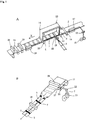
- Fig. 1 illustrates an apparatus for successively making plastic bags of Fig. 3 , according to the invention.
- the plastic bag includes a panel portion, side gusset portions and a fastener portion, as in the case of the plastic bag of Japanese Laid-Open Patent Publication No. 347,788 of 2002 .
- the panel portion is formed of first and second webs of panel material 1 and 2 which are superposed with each other and crosscut into a length, as shown in Fig. 3 .
- the side gusset portions are formed of webs of side gusset material 3 to extend opposite side edges 4 of plastic bag, the webs of side gusset material 3 being also crosscut into a length.
- the web of side gusset material 3 is folded into halves and interposed between the webs of panel material 1 and 2.
- the webs of panel material 1 and 2 and the webs of side gusset material 3 are heat sealed with each other along the opposite side edges 4 of plastic bag so that heat seal portions 4a are formed along the opposite side edges 4 of plastic bag.
- the fastener portion is formed of first, second and third bodies of fastener material 5, 6 and 7 to extend along the top edge 8 of plastic bag.
- the first body of fastener material 5 is joined to the first web of panel material 1 while the second body of fastener material 6 is joined to the second web of panel material 2 within the plastic bag.
- the third body of fastener material 7 is joined to the web of side gusset material 3 within the plastic bag.
- the first and second webs of panel material 1 and 2 are heat sealed with each other and with the webs of side gusset material 3 along the top edge 8 of plastic bag so that a heat seal portion 8a is formed along the top edge 8 of plastic bag.
- the plastic bag is filled with content at the bottom edge 9 thereof, after making the plastic bag.
- the first and second webs of panel material 1 and 2 are then heat sealed with each other and with the webs of side gusset material 3 along the bottom edge 9.
- the plastic bag is torn off and opened along the top edge 8 thereof after being filled with the content so that the content can be discharged or taken out of the plastic bag.
- the first and second bodies of fastener material 5 and 6 are then meshing engaged with each other between the webs of side gusset material 3 and with the third body of fastener material 7 at the positions of the webs of side gusset material 3 so that the plastic bag can be closed by the first, second and third bodies of fastener material 5, 6 and 7.
- the apparatus includes a panel material feeding device comprising feeding rollers 10 to which the first and second webs of panel material 1 and 2 are directed to be superposed with each other.
- the feeding rollers 10 are rotated intermittently by a motor so that the first and second webs of panel material 1 and 2 can be fed longitudinally thereof and intermittently.
- the first web of panel material 1 is a lower web of panel material comprising a plastic film while the second web of panel material 2 is an upper web of panel material comprising a plastic film.
- the feeding direction X is predetermined longitudinally of the webs of panel material 1 and 2.
- the apparatus further includes a fastener material joining device by which a first body of fastener material 5 is joined to the first web of panel material 1 while a second body of fastener material 6 is joined to the second web of panel material 2 before the first and second webs of panel material 1 and 2 are superposed with each other.
- the first and second bodies of fastener material 5 and 6 extend longitudinally of the first and second webs of panel material 1 and 2.
- the first and second bodies of fastener material 5 and 6 are then interposed between the first and second webs of panel material 1 and 2 and aligned and meshing engaged with each other after the first and second webs of panel material 1 and 2 are superposed with each other.
- the apparatus further includes a side gusset material supply device by which a web of side gusset material 3 is withdrawn from a roll 11, folded into halves and supplied to and put on the first web of panel material 1 to extend widthwise of the first web of panel material 1 before the first and second webs of panel material 1 and 2 are superposed with each other.
- the web of side gusset material 3 is then interposed between the first and second webs of panel material 1 and 2 after the first and second webs of panel material 1 and 2 are superposed with each other.
- the first and second bodies of fastener material 5 and 6 comprise parts of hook and loop touch fastener portion, as in the case of those of Japanese Patent Laid-Open Patent Publication No. 347,788 of 2002 .
- the web of side gusset material 3 comprises a plastic film and has a width.
- the first and second webs of panel material 1 and 2 are fed in a state of being superposed with each other, and directed to a guide roller 12.
- the second web of panel material 2 is then directed to a guide roller 13 to be guided by the guide rollers 12 and 13 and pulled upwardly so that the first and second webs of panel material 1 and 2 are fed intermittently to be separated from each other.
- the second web of panel material 2 is directed to a guide roller 14 to be guided by the guide roller 14 so that the first and second webs of panel material 1 and 2 are fed intermittently to be spaced from each other.
- the web of side gusset material 3 is supplied to and put on the first web of panel material 1 to extend widthwise of the first web of panel material 1 after the first and second webs of panel material 1 and 2 are spaced from each other and when the first and second webs of panel material 1 and 2 are stopped temporarily whenever being fed intermittently.
- the first and second bodies of fastener material 5 and 6 are withdrawn from a reel 15, directed to a guide roller 16 and supplied to and interposed between the first and second webs of panel material 1 and 2 before the first and second webs of panel material 1 and 2 are separated from each other, the first body of fastener material 5 being joined to the first web of panel material 1, the second body of fastener material 6 being joined to the second web of panel material 2.
- the first and second bodies of fastener material 5 and 6 are aligned and meshing engaged with each other when being interposed between the first and second webs of panel material 1 and 2.
- the first and second bodies of fastener material 5 and 6 extend longitudinally of the first and second webs of panel material 1 and 2.
- the fastener material joining device comprises a fastener material seal device by which the first body of fastener material 5 is heat sealed with the first web of panel material 1 to be joined thereto while the second body of fastener material 6 is heat sealed with the second web of panel material 2 to be joined thereto.
- the fastener material seal device includes seal bars 17 extending longitudinally of the first and second webs of panel material 1 and 2 to be disposed on opposite sides thereof.
- first and second webs of panel material 1 and 2 and the first and second bodies of fastener material 5 and 6 are sandwiched between and heated by the seal bars 17 so that the first body of fastener material 5 is heat sealed with the first web of panel material 1 to be joined thereto while the second body of fastener material 6 is heat sealed with the second web of panel material 2 to be joined thereto, when the first and second webs of panel material 1 and 2 are stopped temporarily whenever being fed intermittently.
- the second web of panel material 2 is then directed to the guide rollers 12 and 13 so that the first and second webs of panel material 1 and 2 are separated from each other.
- the first and second bodies of fastener material 5 and 6 are pulled by the first and second webs of panel material 1 and 2 to be separated from each other.
- the web of side gusset material 3 has a width twice as much as that of Fig. 3 , which is folded into halves on opposite sides of the longitudinal centerline thereof to be superposed into two layers, as in the case of the apparatus of Japanese Patent Publication No. 3,655,627 .
- the side gusset supply device includes an autohand or finger moved widthwise of the first web of panel material 1.
- the web of side gusset material 3 is gripped and held by the autohand or finger to be pulled and fed widthwise of the first web of panel material 1.
- the side gusset supply device further includes a guide plate engaged with the web of side gusset material 3, the web of side gusset material 3 being guided by the guide plate to be folded into halves when being fed.
- the web of side gusset material 3 is crosscut into a length corresponding to the width of the first and second webs of panel material 1 and 2 after being folded into halves.
- the side gusset material supply device includes a cutter 18 by which the web of side gusset material 3 is crosscut into the length before being supplied to the first web of panel material 1.
- the web of side gusset material 3 is then fed by the autohand or finger to be supplied to and put on the first web of panel material 1.
- the apparatus further includes a temporarily fixing device by which the web of side gusset material 3 is temporarily fixed to the first web of panel material 1 after being supplied to the first web of panel material 1.
- the temporarily fixing device comprises a ultrasonic seal or heat seal device including a seal bar and a receiver 19.
- the first web of panel material 1 and the web of side gusset material 3 are sandwiched between the seal bar and the receiver 19 so that the web of side gusset material 3 is ultrasonic sealed or heat sealed with the first web of panel 1 to be temporarily fixed thereto.
- the first and second webs of panel material 1 and 2 are then fed intermittently again so that the web of side gusset material 3 is fed by the first web of panel material 1.
- the web of side gusset material 3 may be temporarily fixed to the first web of panel material 1 and crosscut into the length, after being supplied to the first web of panel material 1.
- the web of side gusset material 3 may be temporarily fixed to the first web of panel material 1 and torn off into the length, after being supplied to the first web of panel material 1.
- the side gusset material supply device includes a perforating blade by which a perforation is formed in the web of side gusset material 3. The web of side gusset material 3 is then supplied and temporarily fixed to the first web of panel material 1. The perforation comes close to the receiver 19 when the web of side gusset material 3 is supplied to the first web of panel material 1.
- the side gusset material supply device further includes a movable gripper by which the web of side gusset material 3 is gripped and held after temporarily fixed to the first web of panel material 1.
- the gripper is disposed at distances from the receiver 19 and the perforation and moved away from the perforation so that the web of side gusset material 3 is torn off along the perforation.
- a fixed gripper may be disposed between the receiver 19 and the perforation, by which the web of side gusset material 3 is gripped and held along with the first web of panel material 1 to be torn off reliably.
- the web of side gusset material 3 may be torn off into the length before being supplied to the first web of panel material 1.
- the first and second webs of panel material 1 and 2 are then directed to and guided by a guide roller 20 to be superposed with each other again.
- the web of side gusset material 3 is therefore interposed between the first and second webs of panel material 1 and 2.
- the apparatus further includes an additional joining device by which a third body of fastener material 7 is joined to the web of side gusset material 3 after the web of side gusset material 3 is withdrawn from the roll 11 and before the web of side gusset material 3 is folded into halves and supplied to the first web of panel material 1.
- the third body of fastener material 7 extends widthwise of the web of side gusset material 3 and has a length corresponding to the width of the web of side gusset material 3.
- the web of side gusset material 3 is then folded into halves so that the third body of fastener material 7 is folded by the web of side gusset material 3 and interposed between the first and second bodies of fastener material 5 and 6 after the first and second webs of panel material 1 and 2 are superposed with each other, the first and second bodies of fastener material 5 and 6 being aligned and meshing engaged with the third body of fastener material 7.
- the third body of fastener material 7 comprises a part of hook and loop touch fastener portion.
- the third body of fastener material 7 is withdrawn from a reel 21 and directed to and guided by a guide roller 22 to extend toward the web of side gusset material 3.
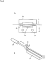
- the apparatus includes an autohand or finger 23 moved widthwise of the web of side gusset material 3, as shown in Fig. 2 .
- the autohand or finger 23 may be connected to and moved by a cylinder 24.
- the third body of fastener material 7 is gripped and held by the autohand or finger 23 to be pulled and fed widthwise of the web of side gusset material 3 and supplied thereto.
- the third body of fastener material 7 is crosscut into the length corresponding to the width of the webs of side gusset material 3 after or before being supplied to the web of side gusset material 3.
- the apparatus includes a cutter 25 by which the third body of fastener material 7 is crosscut into the length.
- the third body of fastener material 7 may be torn off into the length, after or before being supplied to the web of side gusset material 3.
- the apparatus includes a perforating blade by which a perforation is formed in the third body of fastener material 7. The perforation comes close to the web of side gusset material 3 when the third body of fastener material 7 is supplied to the web of side gusset material 3.
- the apparatus further includes a fixed gripper by which the third body of fastener material 7 is gripped and held. The gripper is disposed at distances from the web of side gusset material 3 and the perforation.
- the autohand or finger 23 is then moved away from the perforation so that the third body of fastener material 7 is torn off along the perforation to be disposed at the position of the web of side gusset material 3.
- the apparatus may include a movable gripper moved away from the perforation so that the third body of fastener material 7 is torn off along the perforation.
- the additional fixing device comprises an additional seal device by which the third body of fastener material 7 is heat sealed with the web of side gusset material 3 to be joined thereto.
- the additional seal device includes a seal bar 26 and a receiver 27 extending widthwise of the web of side gusset material 3 and disposed on opposite sides of the web of side gusset material 3 and the third body of fastener material 7. The receiver 27 is moved toward the seal bar 26 after the third body of fastener material 7 is disposed at the position of the web of side gusset material 3.
- the web of side gusset material 3 and the third body of fastener material 7 are therefore sandwiched between the seal bar 26 and the receiver 27 and heated by the seal bar 26 so that the third body of fastener material 7 is heat sealed with the web of side gusset material 3 to be joined thereto.
- the third body of fastener material 7 may include a meshing engaged portion 7a formed integrally with a tape 7b, the tape 7b being heat sealed with the web of side gusset material 3.
- the web of side gusset material 3 is supplied to the first web of panel material 1 and crosscut or torn off into the length corresponding to the width of the first web of panel material 1.
- the third body of fastener material 7 is disposed at the position of the first and second bodies of fastener material 5 and 6.
- the first and second webs of panel material 1 and 2 are then directed to the guide roller 20 and superposed with each other. It should therefore be understood that the third body of fastener material 7 is interposed between the first and second bodies of fastener material 5 and 6, the first and second bodies of fastener material 5 and 6 being aligned and meshing engaged with the third body of fastener material 7, when the first and second webs of panel material 1 and 2 are superposed with each other.
- the apparatus further includes a longitudinal seal device by which the first and second webs of panel material 1 and 2 are heat sealed with each other longitudinally thereof after being superposed with each other and when being stopped temporarily whenever being fed intermittently.
- the longitudinal seal device includes seal bars 28 extending longitudinally of the first and second webs of panel material 1 and 2 to be disposed on opposite sides thereof. The first and second webs of panel material 1 and 2 are sandwiched between and heated by the seal bars 28 to be heat sealed with each other and with the web of side gusset material 3. The first and second webs of panel material 1 and 2 are heat sealed along one of the side edges thereof, to make the heat seal portion 8a of Fig. 3 formed.
- the apparatus further includes a cross seal device by which the first and second webs of panel material 1 and 2 and the web of side gusset material 3 are heat sealed with each other widthwise of the first and second webs of panel material 1 and 2 after the first and second webs of panel material 1 and 2 are superposed with each other and when the first and second webs of panel material 1 and 2 are stopped temporarily whenever being fed intermittently.
- the cross seal device includes seal bars 29 extending widthwise of the first and second webs of panel material 1 and 2 to be disposed on opposite sides thereof.
- the first and second webs of panel material 1 and 2 and the web of side gusset material 3 are sandwiched between and heated by the seal bars 29 to be heat sealed with each other.
- the first and second webs of panel material 1 and 2 and the web of side gusset material 3 are heat sealed along the longitudinal centerline of the web of side gusset material 3, to make the heat seal portion 4a of Fig. 3 formed.
- the apparatus further includes a cutter 30 by which the first and second webs of panel material 1 and 2 and the web of side gusset material 3 are crosscut widthwise of the first and second webs of panel material 1 and 2 after being heat sealed and when the first and second webs of panel material 1 and 2 are stopped temporarily whenever being fed intermittently.
- the first and second webs of panel material 1 and 2 and the web of side gusset material 3 are crosscut along the longitudinal centerline of the web of side gusset material 3, to make the opposite side edge 4 of Fig. 3 formed, the top edge 8 and the bottom edge 9 of Fig. 3 being formed by the opposite side edges of the webs of panel material 1 and 2.
- each of the first and second webs of panel material 1 and 2 and the web of side gusset material 3 comprises a laminated film composed of a sealant laminated on a base material.
- the webs of panel material 1 and 2 have inner surfaces formed by the sealant and outer surfaces formed by the base material when being superposed on each other.
- the web of side gusset material 3 has outer surfaces formed by the sealant and inner surfaces formed by the base material when being folded into halves, as also in the case of the apparatus of Japanese Patent No. 3,655,627 .
- the apparatus can therefore successively make the plastic bags of Fig. 3 .
- the plastic bag includes the panel portion formed by the first and second webs of panel material 1 and 2, the side gusset portion formed by the web of side gusset material 3 and the fastener portion formed by the first, second and third bodies of fastener material 5, 6 and 7.
- the first and second webs of panel material 1 and 2 are fed longitudinally thereof.
- the web of side gusset material 3 is supplied to the first web of panel material 1 to extend widthwise of the first web of panel material 1.
- the first and second webs of panel material 1 and 2 are then heat sealed with each other longitudinally thereof.
- the first and second webs of panel material 1 and 2 and the web of side gusset material 3 are heat sealed with each other widthwise of the first and second webs of panel material 1 and 2.
- the first and second webs of panel material 1 and 2 are then crosscut widthwise thereof, after being heat sealed, as in the case of the apparatus of Japanese Patent No. 3,655,627 .
- the apparatus can therefore successively make the plastic bags at high speed, resulting in high performance.
- the plastic bag includes the fastener portion formed by the first, second and third bodies of fastener material 5, 6 and 7 to have the specific structure.
- the first and second bodies of fastener material 5 and 6 are meshing engaged with each other and with the third body of fastener material 7.
- the plastic bag can therefore be closed by the first, second and third fastener material 5, 6 and 7, as in the case of the plastic bag of Japanese Laid-Open Patent Publication No. 347,788 of 2002 . Accordingly, the plastic bag would be used for various purposes to be high in utility.
- the third body of fastener material 7 is joined to the web of side gusset material 3 after the web of side gusset material 3 is withdrawn from the roll 11, as described previously.
- the third body of fastener material 7 has therefore no problem of position when being joined to the web of side gusset material 3 even if the web of side gusset material 3 is elongated by tension when being withdrawn from the roll 11.
- the third body of fastener material 7 is disposed in position when being supplied to the web of side gusset material 3.
- the third body of fastener material 7 can be interposed between the first and second bodies of fastener material 5 and 6 after the first and second webs of panel material 1 and 2 are superposed with each other.
- the first and second bodies of fastener material 5 and 6 are aligned with the third body of fastener material 7.
- the third body of fastener material 7 is joined to the web of side gusset material 3 before the web of side gusset material 3 is folded into halves.
- the third body of fastener material 7 is joined to the web of side gusset material 3 which is not folded. It can therefore be joined without difficulty.
- the third body of fastener material 7 is then folded by the web of side gusset material 3 when the web of side gusset material 3 is folded into halves.
- the third body of fastener material 7 has therefore not to be folded into halves when being supplied to the web of side gusset material 3.
- the apparatus may be arranged to successively make plastic bags of Fig. 4 .
- the plastic bag is filled with content at the top edge 8 thereof, after making the plastic bag.
- the first and second webs of panel material 1 and 2 are then heat sealed with each other and with the webs of side gusset material 3 along the top edge 8.
- the plastic bag also includes the panel portion, the side gusset portions and the fastener portion.
- the panel portion is formed by the first and second webs of panel material 1 and 2.
- the side gusset portion is formed by the web of side gusset material 3.
- the fastener portion is formed by the first, second and third bodies of fastener material 5, 6 and 7.
- the plastic bag includes a bottom gusset portion formed of a web of bottom gusset material 31.
- the first and second webs of panel material 1 and 2 and the web of bottom gusset material 31 are heat sealed with each other along the bottom edge 9 of plastic bag so that a heat seal portion 9a is formed along the bottom edge 9 of plastic bag.
- the first or second web of panel material 1 or 2 is folded and folded back along a longitudinal folded line and a longitudinal folded back line to have a folded portion formed therein, the web of bottom gusset material 31 being formed by the folded portion, as in the case of the apparatus of Japanese Patent Publication No. 3,655,627 .
- the apparatus may include a bottom gusset material supply device by which the web of bottom gusset material 31 is supplied to be interposed between the first and second webs of panel material 1 and 2.
- the apparatus further includes a longitudinal seal device by which the first and second webs of panel material 1 and 2 and the web of bottom gusset material 31 are heat sealed with each other longitudinally of the first and second webs of panel material 1 and 2.
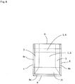
- the first and second bodies of fastener material 5 and 6 may include meshing engaged portions 5a and 6a formed integrally with tapes 5b and 6b, as shown in Fig. 5 .
- the fastener material seal device may include seal bars 17 by which the first and second webs of panel material 1 and 2 and the first and second bodies of fastener material 5 and 6 are heat sealed with each other, the seal bars 17 being channel shaped.
- plates 32 are inserted between the tapes 5b and 6b on opposite sides of the meshing engaged portions 5a and 6a.
- the first web of panel material 1 and the tape 5b are sandwiched between the seal bar 17 and the plate 32 to be heat sealed with each other while the second web of panel material 2 and the tape 6b are sandwiched between the seal bar 17 and the plate 32 to be heat sealed with each other.
- pushers may be disposed on opposite sides of the first and second webs of panel material 1 and 2 so that the first and second webs of panel material 1 and 2, the web of side gusset material 3 and the first, second and third bodies of fastener material 5, 6 and 7 are compressed by the pushers to decrease the thickness in all, before being heat sealed.
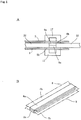
- Fig. 6 illustrates another embodiment in which the first and second bodies of fastener material 5 and 6 are divided into divided portions so that clearances 33 are formed between the divided portions ( Fig. 6 A) .
- the first and second webs of panel material 1 and 2 and the web of side gusset material 3 are then heat sealed with each other at the clearance 33 by the seal bars 29.
- clearances 34 are formed between the third body of fastener material 7 and the opposite side edges of the web of side gusset material 3 ( Fig. 6B ).
- the third body of fastener material 7 is divided into four portions so that clearances 35 are formed between the divided portions 7.
- the divided portions 7 are disposed on opposite sides of the longitudinal centerline of the web of side gusset material 3 along which the web of side gusset material 3 is folded into halves.
- the first and second webs of panel material 1 and 2 and the web of side gusset material 3 are heat sealed with each other conveniently by the seal bars 29 by reason of no first, second and third bodies of fastener material 5, 6 and 7 being disposed ( Fig. 6 C) .
- the third body of fastener material 7 may be divided into two portions ( Fig. 6 D) .
Landscapes
- Making Paper Articles (AREA)
Claims (8)
- Vorrichtung zum aufeinanderfolgenden Herstellen von Kunststoffbeuteln, von denen jeder einen Tafelbereich, Seiteneinsatzbereich und einen Befestigungsbereich enthält, welche Vorrichtung aufweist:eine Tafelmaterial-Zuführungsvorrichtung (10), durch die eine erste und eine zweite Bahn aus Tafelmaterial (1, 2) übereinander angeordnet und in ihrer Längsrichtung zugeführt werden;eine Befestigungsmaterial-Verbindungsvorrichtung (17), durch die ein erster Körper aus Befestigungsmaterial (5) mit der ersten Bahn aus Tafelmaterial (1) verbunden wird, während ein zweiter Körper aus Befestigungsmaterial (6) mit der zweiten Bahn aus Tafelmaterial (2) verbunden wird, bevor die erste und die zweite Bahn aus Tafelmaterial (1, 2) übereinander gelegt werden, wobei der erste und der zweite Körper aus Befestigungsmaterial (5, 6) sich in Längsrichtung der ersten und der zweiten Bahn aus Tafelmaterial (1, 2) erstrecken, der erste und der zweite Körper aus Befestigungsmaterial (5, 6) dann zwischen der ersten und der zweiten Bahn aus Tafelmaterial (1, 2) angeordnet und miteinander ausgerichtet werden, nachdem die erste und die zweite Bahn aus Tafelmaterial (1, 2) übereinander angeordnet wurden;welche Vorrichtung gekennzeichnet ist durch:Führungsrollen (12, 13, 14), durch die die erste und die zweite Bahn aus Tafelmaterial (1, 2) voneinander getrennt werden, um einen gegenseitigen Abstand aufzuweisen, wodurch die Bahnen (1, 2) in einem Zustand zugeführt werden, in welchem sie übereinander gelegt und zu einer Führungsrolle (12) hin gerichtet sind, wodurch die zweite Bahn (2) dann zu einer Führungsrolle (13) hin gerichtet wird, um durch die Führungsrollen (12, 13) geführt und aufwärts gezogen zu werden, so dass die erste und die zweite Bahn (1, 2) intermittierend zugeführt werden, um in einen gegenseitigen Abstand gebracht zu werden, und wodurch die zweite Bahn (2) dann zu einer Führungsrolle (14) gerichtet wird, um so durch die Führungsrolle (14) geführt zu werden, dass die erste und die zweite Bahn (1, 2) intermittierend zugeführt werden, um in einen gegenseitigen Abstand gebracht zu werden, eine weitere Führungsrolle (20), durch die die erste und die zweite Bahn aus Tafelmaterial (1, 2) wieder übereinandergelegt werden;eine Seiteneinsatzmaterial-Zuführungsvorrichtung, durch die eine Bahn aus Seiteneinsatzmaterial (3) von einer Rolle (11) gezogen wird, in Hälften gefaltet und zu der ersten Bahn aus Tafelmaterial (1) geliefert wird, um sich in Breitenrichtung der ersten Bahn aus Tafelmaterial (1) zu erstrecken, bevor die erste und die zweite Bahn aus Tafelmaterial (1, 2) wieder übereinander gelegt werden, wobei die Bahn aus Seiteneinsatzmaterial (3) eine Breite hat, die Bahn aus Seiteneinsatzmaterial (3) zwischen der ersten und der zweiten Bahn aus Tafelmaterial (1, 2) angeordnet wird, nachdem die erste und die zweite Bahn aus Tafelmaterial (1, 2) wieder übereinandergelegt wurden; undeine zusätzliche Verbindungsvorrichtung (26, 27), durch die ein dritter Körper aus Befestigungsmaterial (7) mit der Bahn aus Seiteneinsatzmaterial (3) verbunden wird, nachdem die Bahn aus Seiteneinsatzmaterial (3) von der Rolle (11) gezogen wurde, und bevor die Bahn aus Seiteneinsatzmaterial (3) in Hälften gefaltet und zu der ersten Bahn aus Tafelmaterial (1) geliefert wird, wobei sich der dritte Körper aus Befestigungsmaterial (7) in Breitenrichtung der Bahn aus Seiteneinsatzmaterial (3) erstreckt und eine Länge entsprechend der Breite der Bahn aus Seiteneinsatzmaterial (3) hat, die Bahn aus Seiteneinsatzmaterial (3) dann in Hälften gefaltet und zu der ersten Bahn aus Tafelmaterial (1) geliefert wird, so dass der dritte Körper aus Befestigungsmaterial (7) durch die Bahn aus Seiteneinsatzmaterial (3) gefaltet und zwischen dem ersten und dem zweiten Körper aus Befestigungsmaterial (5, 6) angeordnet wird, nachdem die erste und die zweite Bahn aus Tafelmaterial (1, 2) wieder übereingelegt wurden, der erste und der zweite Körper aus Befestigungsmaterial (5, 6) mit dem dritten Körper aus Befestigungsmaterial (7) ausgerichtet werden, der Tafelbereich aus der ersten und der zweiten Bahn aus Tafelmaterial (1, 2) gebildet wird, der Seiteneinsatzbereich aus der Bahn aus Seiteneinsatzmaterial (3) gebildet wird, und der Befestigungsbereich aus dem ersten, zweiten und dritten Körper aus Befestigungsmaterial (5, 6, 7) gebildet wird.
- Vorrichtung nach Anspruch 1, bei der der erste, zweite und dritte Körper aus Befestigungsmaterial (5, 6, 7) Teile eines Klettverschluss-Befestigungsbereichs aufweisen.
- Vorrichtung nach Anspruch 1, bei der die Bahn aus Seiteneinsatzmaterial (3) in eine Länge entsprechend der Breite der ersten und der zweiten Bahn aus Tafelmaterial (1, 2) quergeschnitten oder abgerissen ist, nachdem es in Hälften gefaltet wurde und nachdem oder bevor es zu der ersten Bahn aus Tafelmaterial (1) geliefert wurde/wird.
- Vorrichtung nach Anspruch 1, bei der der dritte Körper aus Befestigungsmaterial (7) in die Länge entsprechend der Breite der Bahn aus Seiteneinsatzmaterial (3) quergeschnitten oder abgerissen wird, nachdem oder bevor er zu der Bahn aus Seiteneinsatzmaterial (3) geliefert wurde/wird.
- Vorrichtung nach Anspruch 1, bei der die erste und die zweite Bahn aus Tafelmaterial (1, 2) in einem Zustand, in welchem sie übereinandergelegt sind, zugeführt werden, die erste und die zweite Bahn aus Tafelmaterial (1, 2) dann voneinander getrennt werden, um einen gegenseitigen Abstand aufzuweisen, die Bahn aus Seiteneinsatzmaterial (3) zu der ersten Bahn aus Tafelmaterial (1) geliefert wird, nachdem die erste und die zweite Bahn aus Tafelmaterial (1, 2) einen gegenseitigen Abstand aufweisen, die erste und die zweite Bahn aus Tafelmaterial (1, 2) dann wieder übereinandergelegt werden, so dass die Bahn aus Seiteneinsatzmaterial (3) zwischen der ersten und der zweiten Bahn aus Tafelmaterial (1, 2) angeordnet wird, während der dritte Körper aus Befestigungsmaterial (7) zwischen dem ersten und dem zweiten Körper aus Befestigungsmaterial (5, 6) angeordnet wird.
- Vorrichtung nach Anspruch 5, bei der der erste und der zweite Körper aus Befestigungsmaterial (5, 6) zwischen der ersten und der zweiten Bahn aus Tafelmaterial (1, 2) angeordnet werden, bevor die erste und die zweite Bahn aus Tafelmaterial (1, 2) voneinander getrennt werden, der erste Körper aus Befestigungsmaterial (5) mit der ersten Bahn aus Tafelmaterial (1) verbunden wird, der zweite Körper aus Befestigungsmaterial (6) mit der zweiten Bahn aus Tafelmaterial (2) verbunden wird.
- Vorrichtung nach Anspruch 1, bei der die Befestigungsmaterial-Verbindungsvorrichtung eine Befestigungsmaterial-Versiegelungsvorrichtung (17) aufweist, durch die der erste Körper aus Befestigungsmaterial (5) mit der ersten Bahn aus Tafelmaterial (1) wärmeversiegelt wird, um mit dieser verbunden zu werden, während der zweite Körper aus Befestigungsmaterial (6) mit der zweiten Bahn aus Tafelmaterial (2) wärmeversiegelt wird, um mit dieser verbunden zu werden, die zusätzliche Verbindungsvorrichtung eine zusätzliche Versiegelungsvorrichtung (26, 27) aufweist, durch die der dritte Körper aus Befestigungsmaterial (7) mit der Bahn aus Seiteneinsatzmaterial (3) wärmeversiegelt wird, um mit dieser verbunden zu werden.
- Vorrichtung nach Anspruch 1, weiterhin aufweisend:eine Längsversiegelungsvorrichtung (28), durch die die erste und die zweite Bahn aus Tafelmaterial (1, 2) in ihrer Längsrichtung miteinander wärmeversiegelt werden, nachdem sie wieder übereinandergelegt wurden;eine Querversiegelungsvorrichtung (29), durch die die erste und die zweite Bahn aus Tafelmaterial (1, 2) und die Bahn aus Seiteneinsatzmaterial (3) in Breitenrichtung der ersten und der zweiten Bahn aus Tafelmaterial (1, 2) miteinander wärmeversiegelt werden, nachdem die erste und die zweite Bahn aus Tafelmaterial (1, 2) wieder übereinandergelegt wurden; undeine Schneidvorrichtung (30), durch die die erste und die zweite Bahn aus Tafelmaterial (1, 2) in Breitenrichtung quergeschnitten werden, nachdem sie wärmeversiegelt wurden.
Priority Applications (2)
| Application Number | Priority Date | Filing Date | Title |
|---|---|---|---|
| EP14192980.2A EP3020545B1 (de) | 2014-11-13 | 2014-11-13 | Vorrichtung zur herstellung von kunststoffbeuteln |
| DK14192980.2T DK3020545T3 (en) | 2014-11-13 | 2014-11-13 | Device for making plastic bags |
Applications Claiming Priority (1)
| Application Number | Priority Date | Filing Date | Title |
|---|---|---|---|
| EP14192980.2A EP3020545B1 (de) | 2014-11-13 | 2014-11-13 | Vorrichtung zur herstellung von kunststoffbeuteln |
Publications (2)
| Publication Number | Publication Date |
|---|---|
| EP3020545A1 EP3020545A1 (de) | 2016-05-18 |
| EP3020545B1 true EP3020545B1 (de) | 2018-02-28 |
Family
ID=51904743
Family Applications (1)
| Application Number | Title | Priority Date | Filing Date |
|---|---|---|---|
| EP14192980.2A Not-in-force EP3020545B1 (de) | 2014-11-13 | 2014-11-13 | Vorrichtung zur herstellung von kunststoffbeuteln |
Country Status (2)
| Country | Link |
|---|---|
| EP (1) | EP3020545B1 (de) |
| DK (1) | DK3020545T3 (de) |
Families Citing this family (2)
| Publication number | Priority date | Publication date | Assignee | Title |
|---|---|---|---|---|
| FR3094351B1 (fr) | 2019-03-28 | 2021-03-19 | Coveris Flexibles France | Procédé de fabrication d’une pluralité de sacs d’emballage à ouvertures partielles et selon une technique transversale |
| CN111217030A (zh) * | 2020-03-18 | 2020-06-02 | 常州美昇进出口有限责任公司 | 一种防儿童开启的功能袋、生产工艺流程和生产设备 |
Family Cites Families (3)
| Publication number | Priority date | Publication date | Assignee | Title |
|---|---|---|---|---|
| DE20106175U1 (de) | 2001-04-07 | 2002-08-14 | Bischof und Klein GmbH & Co. KG, 49525 Lengerich | Seitenfaltenbeutel oder -sack aus flexiblem schweißbarem Material |
| JP3655627B2 (ja) | 2002-07-24 | 2005-06-02 | トタニ技研工業株式会社 | 製袋機 |
| JP5439622B1 (ja) * | 2013-07-10 | 2014-03-12 | トタニ技研工業株式会社 | ファスナ材進行方向変換装置 |
-
2014
- 2014-11-13 EP EP14192980.2A patent/EP3020545B1/de not_active Not-in-force
- 2014-11-13 DK DK14192980.2T patent/DK3020545T3/en active
Non-Patent Citations (1)
| Title |
|---|
| None * |
Also Published As
| Publication number | Publication date |
|---|---|
| DK3020545T3 (en) | 2018-04-23 |
| EP3020545A1 (de) | 2016-05-18 |
Similar Documents
| Publication | Publication Date | Title |
|---|---|---|
| US9662852B2 (en) | Plastic bag making apparatus | |
| US10369759B2 (en) | Plastic bag making apparatus | |
| US8414465B2 (en) | Plastic bag making apparatus | |
| EP2353855B1 (de) | Vorrichtung zur Herstellung von Kunststoffbeuteln | |
| EP1541332B1 (de) | Beutelherstellungsmaschine | |
| US8579779B2 (en) | Plastic bag making apparatus | |
| US8579780B2 (en) | Plastic bag making apparatus | |
| US10953620B2 (en) | Plastic bag making apparatus | |
| KR102568473B1 (ko) | 지퍼 테이프를 갖는 주머니체, 주머니체, 주머니체의 제조 방법 및 주머니체의 제조 장치 | |
| EP3157828B1 (de) | Verfahren zur herstellung einer verpackung mit integriertem griff an der seitenfalte und verpackung dafür | |
| EP3020545B1 (de) | Vorrichtung zur herstellung von kunststoffbeuteln | |
| US9346249B2 (en) | Fastener material advancing direction changing apparatus | |
| CA2870663C (en) | Plastic bag making apparatus | |
| AU2014262211A1 (en) | Plastic bag making apparatus | |
| EP2500165B1 (de) | Vorrichtung zur Herstellung von Kunststoffbeuteln | |
| JP5635651B1 (ja) | 製袋機 |
Legal Events
| Date | Code | Title | Description |
|---|---|---|---|
| PUAI | Public reference made under article 153(3) epc to a published international application that has entered the european phase |
Free format text: ORIGINAL CODE: 0009012 |
|
| 17P | Request for examination filed |
Effective date: 20141113 |
|
| AK | Designated contracting states |
Kind code of ref document: A1 Designated state(s): AL AT BE BG CH CY CZ DE DK EE ES FI FR GB GR HR HU IE IS IT LI LT LU LV MC MK MT NL NO PL PT RO RS SE SI SK SM TR |
|
| AX | Request for extension of the european patent |
Extension state: BA ME |
|
| 17Q | First examination report despatched |
Effective date: 20170315 |
|
| REG | Reference to a national code |
Ref country code: DE Ref legal event code: R079 Ref document number: 602014021551 Country of ref document: DE Free format text: PREVIOUS MAIN CLASS: B31B0001900000 Ipc: B31B0070810000 |
|
| GRAP | Despatch of communication of intention to grant a patent |
Free format text: ORIGINAL CODE: EPIDOSNIGR1 |
|
| RIC1 | Information provided on ipc code assigned before grant |
Ipc: B31B 70/00 20170101ALI20170807BHEP Ipc: B31B 70/81 20170101AFI20170807BHEP |
|
| INTG | Intention to grant announced |
Effective date: 20170907 |
|
| GRAS | Grant fee paid |
Free format text: ORIGINAL CODE: EPIDOSNIGR3 |
|
| GRAA | (expected) grant |
Free format text: ORIGINAL CODE: 0009210 |
|
| AK | Designated contracting states |
Kind code of ref document: B1 Designated state(s): AL AT BE BG CH CY CZ DE DK EE ES FI FR GB GR HR HU IE IS IT LI LT LU LV MC MK MT NL NO PL PT RO RS SE SI SK SM TR |
|
| REG | Reference to a national code |
Ref country code: GB Ref legal event code: FG4D Ref country code: CH Ref legal event code: EP |
|
| REG | Reference to a national code |
Ref country code: AT Ref legal event code: REF Ref document number: 973649 Country of ref document: AT Kind code of ref document: T Effective date: 20180315 |
|
| REG | Reference to a national code |
Ref country code: IE Ref legal event code: FG4D |
|
| REG | Reference to a national code |
Ref country code: DE Ref legal event code: R096 Ref document number: 602014021551 Country of ref document: DE |
|
| REG | Reference to a national code |
Ref country code: DK Ref legal event code: T3 Effective date: 20180420 |
|
| REG | Reference to a national code |
Ref country code: NL Ref legal event code: MP Effective date: 20180228 |
|
| REG | Reference to a national code |
Ref country code: LT Ref legal event code: MG4D |
|
| PG25 | Lapsed in a contracting state [announced via postgrant information from national office to epo] |
Ref country code: NL Free format text: LAPSE BECAUSE OF FAILURE TO SUBMIT A TRANSLATION OF THE DESCRIPTION OR TO PAY THE FEE WITHIN THE PRESCRIBED TIME-LIMIT Effective date: 20180228 Ref country code: ES Free format text: LAPSE BECAUSE OF FAILURE TO SUBMIT A TRANSLATION OF THE DESCRIPTION OR TO PAY THE FEE WITHIN THE PRESCRIBED TIME-LIMIT Effective date: 20180228 Ref country code: LT Free format text: LAPSE BECAUSE OF FAILURE TO SUBMIT A TRANSLATION OF THE DESCRIPTION OR TO PAY THE FEE WITHIN THE PRESCRIBED TIME-LIMIT Effective date: 20180228 Ref country code: HR Free format text: LAPSE BECAUSE OF FAILURE TO SUBMIT A TRANSLATION OF THE DESCRIPTION OR TO PAY THE FEE WITHIN THE PRESCRIBED TIME-LIMIT Effective date: 20180228 Ref country code: NO Free format text: LAPSE BECAUSE OF FAILURE TO SUBMIT A TRANSLATION OF THE DESCRIPTION OR TO PAY THE FEE WITHIN THE PRESCRIBED TIME-LIMIT Effective date: 20180528 Ref country code: CY Free format text: LAPSE BECAUSE OF FAILURE TO SUBMIT A TRANSLATION OF THE DESCRIPTION OR TO PAY THE FEE WITHIN THE PRESCRIBED TIME-LIMIT Effective date: 20180228 Ref country code: FI Free format text: LAPSE BECAUSE OF FAILURE TO SUBMIT A TRANSLATION OF THE DESCRIPTION OR TO PAY THE FEE WITHIN THE PRESCRIBED TIME-LIMIT Effective date: 20180228 |
|
| PG25 | Lapsed in a contracting state [announced via postgrant information from national office to epo] |
Ref country code: LV Free format text: LAPSE BECAUSE OF FAILURE TO SUBMIT A TRANSLATION OF THE DESCRIPTION OR TO PAY THE FEE WITHIN THE PRESCRIBED TIME-LIMIT Effective date: 20180228 Ref country code: SE Free format text: LAPSE BECAUSE OF FAILURE TO SUBMIT A TRANSLATION OF THE DESCRIPTION OR TO PAY THE FEE WITHIN THE PRESCRIBED TIME-LIMIT Effective date: 20180228 Ref country code: BG Free format text: LAPSE BECAUSE OF FAILURE TO SUBMIT A TRANSLATION OF THE DESCRIPTION OR TO PAY THE FEE WITHIN THE PRESCRIBED TIME-LIMIT Effective date: 20180528 Ref country code: GR Free format text: LAPSE BECAUSE OF FAILURE TO SUBMIT A TRANSLATION OF THE DESCRIPTION OR TO PAY THE FEE WITHIN THE PRESCRIBED TIME-LIMIT Effective date: 20180529 Ref country code: RS Free format text: LAPSE BECAUSE OF FAILURE TO SUBMIT A TRANSLATION OF THE DESCRIPTION OR TO PAY THE FEE WITHIN THE PRESCRIBED TIME-LIMIT Effective date: 20180228 |
|
| PG25 | Lapsed in a contracting state [announced via postgrant information from national office to epo] |
Ref country code: AL Free format text: LAPSE BECAUSE OF FAILURE TO SUBMIT A TRANSLATION OF THE DESCRIPTION OR TO PAY THE FEE WITHIN THE PRESCRIBED TIME-LIMIT Effective date: 20180228 Ref country code: EE Free format text: LAPSE BECAUSE OF FAILURE TO SUBMIT A TRANSLATION OF THE DESCRIPTION OR TO PAY THE FEE WITHIN THE PRESCRIBED TIME-LIMIT Effective date: 20180228 Ref country code: PL Free format text: LAPSE BECAUSE OF FAILURE TO SUBMIT A TRANSLATION OF THE DESCRIPTION OR TO PAY THE FEE WITHIN THE PRESCRIBED TIME-LIMIT Effective date: 20180228 Ref country code: RO Free format text: LAPSE BECAUSE OF FAILURE TO SUBMIT A TRANSLATION OF THE DESCRIPTION OR TO PAY THE FEE WITHIN THE PRESCRIBED TIME-LIMIT Effective date: 20180228 |
|
| REG | Reference to a national code |
Ref country code: DE Ref legal event code: R097 Ref document number: 602014021551 Country of ref document: DE |
|
| PG25 | Lapsed in a contracting state [announced via postgrant information from national office to epo] |
Ref country code: SM Free format text: LAPSE BECAUSE OF FAILURE TO SUBMIT A TRANSLATION OF THE DESCRIPTION OR TO PAY THE FEE WITHIN THE PRESCRIBED TIME-LIMIT Effective date: 20180228 Ref country code: CZ Free format text: LAPSE BECAUSE OF FAILURE TO SUBMIT A TRANSLATION OF THE DESCRIPTION OR TO PAY THE FEE WITHIN THE PRESCRIBED TIME-LIMIT Effective date: 20180228 Ref country code: SK Free format text: LAPSE BECAUSE OF FAILURE TO SUBMIT A TRANSLATION OF THE DESCRIPTION OR TO PAY THE FEE WITHIN THE PRESCRIBED TIME-LIMIT Effective date: 20180228 |
|
| PLBE | No opposition filed within time limit |
Free format text: ORIGINAL CODE: 0009261 |
|
| STAA | Information on the status of an ep patent application or granted ep patent |
Free format text: STATUS: NO OPPOSITION FILED WITHIN TIME LIMIT |
|
| 26N | No opposition filed |
Effective date: 20181129 |
|
| PG25 | Lapsed in a contracting state [announced via postgrant information from national office to epo] |
Ref country code: SI Free format text: LAPSE BECAUSE OF FAILURE TO SUBMIT A TRANSLATION OF THE DESCRIPTION OR TO PAY THE FEE WITHIN THE PRESCRIBED TIME-LIMIT Effective date: 20180228 |
|
| REG | Reference to a national code |
Ref country code: DK Ref legal event code: EBP Effective date: 20181130 |
|
| REG | Reference to a national code |
Ref country code: CH Ref legal event code: PL |
|
| GBPC | Gb: european patent ceased through non-payment of renewal fee |
Effective date: 20181113 |
|
| PG25 | Lapsed in a contracting state [announced via postgrant information from national office to epo] |
Ref country code: LU Free format text: LAPSE BECAUSE OF NON-PAYMENT OF DUE FEES Effective date: 20181113 Ref country code: MC Free format text: LAPSE BECAUSE OF FAILURE TO SUBMIT A TRANSLATION OF THE DESCRIPTION OR TO PAY THE FEE WITHIN THE PRESCRIBED TIME-LIMIT Effective date: 20180228 |
|
| REG | Reference to a national code |
Ref country code: BE Ref legal event code: MM Effective date: 20181130 |
|
| REG | Reference to a national code |
Ref country code: IE Ref legal event code: MM4A |
|
| PG25 | Lapsed in a contracting state [announced via postgrant information from national office to epo] |
Ref country code: LI Free format text: LAPSE BECAUSE OF NON-PAYMENT OF DUE FEES Effective date: 20181130 Ref country code: CH Free format text: LAPSE BECAUSE OF NON-PAYMENT OF DUE FEES Effective date: 20181130 |
|
| PG25 | Lapsed in a contracting state [announced via postgrant information from national office to epo] |
Ref country code: IE Free format text: LAPSE BECAUSE OF NON-PAYMENT OF DUE FEES Effective date: 20181113 Ref country code: DK Free format text: LAPSE BECAUSE OF NON-PAYMENT OF DUE FEES Effective date: 20181130 |
|
| PG25 | Lapsed in a contracting state [announced via postgrant information from national office to epo] |
Ref country code: BE Free format text: LAPSE BECAUSE OF NON-PAYMENT OF DUE FEES Effective date: 20181130 |
|
| PG25 | Lapsed in a contracting state [announced via postgrant information from national office to epo] |
Ref country code: GB Free format text: LAPSE BECAUSE OF NON-PAYMENT OF DUE FEES Effective date: 20181113 |
|
| PG25 | Lapsed in a contracting state [announced via postgrant information from national office to epo] |
Ref country code: MT Free format text: LAPSE BECAUSE OF NON-PAYMENT OF DUE FEES Effective date: 20181113 |
|
| PG25 | Lapsed in a contracting state [announced via postgrant information from national office to epo] |
Ref country code: TR Free format text: LAPSE BECAUSE OF FAILURE TO SUBMIT A TRANSLATION OF THE DESCRIPTION OR TO PAY THE FEE WITHIN THE PRESCRIBED TIME-LIMIT Effective date: 20180228 |
|
| PGFP | Annual fee paid to national office [announced via postgrant information from national office to epo] |
Ref country code: AT Payment date: 20191121 Year of fee payment: 6 |
|
| PG25 | Lapsed in a contracting state [announced via postgrant information from national office to epo] |
Ref country code: PT Free format text: LAPSE BECAUSE OF FAILURE TO SUBMIT A TRANSLATION OF THE DESCRIPTION OR TO PAY THE FEE WITHIN THE PRESCRIBED TIME-LIMIT Effective date: 20180228 |
|
| PG25 | Lapsed in a contracting state [announced via postgrant information from national office to epo] |
Ref country code: MK Free format text: LAPSE BECAUSE OF NON-PAYMENT OF DUE FEES Effective date: 20180228 Ref country code: HU Free format text: LAPSE BECAUSE OF FAILURE TO SUBMIT A TRANSLATION OF THE DESCRIPTION OR TO PAY THE FEE WITHIN THE PRESCRIBED TIME-LIMIT; INVALID AB INITIO Effective date: 20141113 |
|
| PG25 | Lapsed in a contracting state [announced via postgrant information from national office to epo] |
Ref country code: IS Free format text: LAPSE BECAUSE OF FAILURE TO SUBMIT A TRANSLATION OF THE DESCRIPTION OR TO PAY THE FEE WITHIN THE PRESCRIBED TIME-LIMIT Effective date: 20180628 |
|
| REG | Reference to a national code |
Ref country code: AT Ref legal event code: UEP Ref document number: 973649 Country of ref document: AT Kind code of ref document: T Effective date: 20180228 |
|
| REG | Reference to a national code |
Ref country code: AT Ref legal event code: MM01 Ref document number: 973649 Country of ref document: AT Kind code of ref document: T Effective date: 20201113 |
|
| PG25 | Lapsed in a contracting state [announced via postgrant information from national office to epo] |
Ref country code: AT Free format text: LAPSE BECAUSE OF NON-PAYMENT OF DUE FEES Effective date: 20201113 |
|
| PGFP | Annual fee paid to national office [announced via postgrant information from national office to epo] |
Ref country code: FR Payment date: 20211122 Year of fee payment: 8 Ref country code: DE Payment date: 20211118 Year of fee payment: 8 |
|
| PGFP | Annual fee paid to national office [announced via postgrant information from national office to epo] |
Ref country code: IT Payment date: 20211119 Year of fee payment: 8 |
|
| REG | Reference to a national code |
Ref country code: DE Ref legal event code: R119 Ref document number: 602014021551 Country of ref document: DE |
|
| PG25 | Lapsed in a contracting state [announced via postgrant information from national office to epo] |
Ref country code: IT Free format text: LAPSE BECAUSE OF NON-PAYMENT OF DUE FEES Effective date: 20221113 Ref country code: DE Free format text: LAPSE BECAUSE OF NON-PAYMENT OF DUE FEES Effective date: 20230601 |
|
| PG25 | Lapsed in a contracting state [announced via postgrant information from national office to epo] |
Ref country code: FR Free format text: LAPSE BECAUSE OF NON-PAYMENT OF DUE FEES Effective date: 20221130 |