EP3020544B1 - Verfahren und vorrichtung zum verdichten und einschliessen von abfall - Google Patents
Verfahren und vorrichtung zum verdichten und einschliessen von abfall Download PDFInfo
- Publication number
- EP3020544B1 EP3020544B1 EP15191854.7A EP15191854A EP3020544B1 EP 3020544 B1 EP3020544 B1 EP 3020544B1 EP 15191854 A EP15191854 A EP 15191854A EP 3020544 B1 EP3020544 B1 EP 3020544B1
- Authority
- EP
- European Patent Office
- Prior art keywords
- piston
- container
- bag
- lid
- reduced pressure
- Prior art date
- Legal status (The legal status is an assumption and is not a legal conclusion. Google has not performed a legal analysis and makes no representation as to the accuracy of the status listed.)
- Not-in-force
Links
Images
Classifications
-
- B—PERFORMING OPERATIONS; TRANSPORTING
- B65—CONVEYING; PACKING; STORING; HANDLING THIN OR FILAMENTARY MATERIAL
- B65B—MACHINES, APPARATUS OR DEVICES FOR, OR METHODS OF, PACKAGING ARTICLES OR MATERIALS; UNPACKING
- B65B1/00—Packaging fluent solid material, e.g. powders, granular or loose fibrous material, loose masses of small articles, in individual containers or receptacles, e.g. bags, sacks, boxes, cartons, cans, or jars
- B65B1/20—Reducing volume of filled material
- B65B1/24—Reducing volume of filled material by mechanical compression
-
- B—PERFORMING OPERATIONS; TRANSPORTING
- B30—PRESSES
- B30B—PRESSES IN GENERAL
- B30B9/00—Presses specially adapted for particular purposes
- B30B9/30—Presses specially adapted for particular purposes for baling; Compression boxes therefor
- B30B9/3042—Containers provided with, or connectable to, compactor means
- B30B9/3046—Containers with built-in compactor means
-
- B—PERFORMING OPERATIONS; TRANSPORTING
- B65—CONVEYING; PACKING; STORING; HANDLING THIN OR FILAMENTARY MATERIAL
- B65F—GATHERING OR REMOVAL OF DOMESTIC OR LIKE REFUSE
- B65F1/00—Refuse receptacles; Accessories therefor
- B65F1/04—Refuse receptacles; Accessories therefor with removable inserts
- B65F1/06—Refuse receptacles; Accessories therefor with removable inserts with flexible inserts, e.g. bags or sacks
- B65F1/065—Refuse receptacles; Accessories therefor with removable inserts with flexible inserts, e.g. bags or sacks with means aiding the insertion of the flexible insert
-
- B—PERFORMING OPERATIONS; TRANSPORTING
- B65—CONVEYING; PACKING; STORING; HANDLING THIN OR FILAMENTARY MATERIAL
- B65F—GATHERING OR REMOVAL OF DOMESTIC OR LIKE REFUSE
- B65F1/00—Refuse receptacles; Accessories therefor
- B65F1/14—Other constructional features; Accessories
- B65F1/1405—Compressing means incorporated in, or specially adapted for, refuse receptacles
-
- B—PERFORMING OPERATIONS; TRANSPORTING
- B65—CONVEYING; PACKING; STORING; HANDLING THIN OR FILAMENTARY MATERIAL
- B65B—MACHINES, APPARATUS OR DEVICES FOR, OR METHODS OF, PACKAGING ARTICLES OR MATERIALS; UNPACKING
- B65B67/00—Apparatus or devices facilitating manual packaging operations; Sack holders
- B65B67/12—Sack holders, i.e. stands or frames with means for supporting sacks in the open condition to facilitate filling with articles or materials
- B65B2067/1283—Means for gathering, closing or sealing the sacks
-
- B—PERFORMING OPERATIONS; TRANSPORTING
- B65—CONVEYING; PACKING; STORING; HANDLING THIN OR FILAMENTARY MATERIAL
- B65F—GATHERING OR REMOVAL OF DOMESTIC OR LIKE REFUSE
- B65F2210/00—Equipment of refuse receptacles
- B65F2210/167—Sealing means
Definitions
- the present invention relates to a method which can be used in compacting and, if necessary, sealing of, for example, products, goods or waste.
- the present invention further relates to a device for carrying out said method.
- US-5,083,509 discloses a method and compactor device wherein an airtight bag is placed on the upper surface of a piston which is movable inside a container, which can be closed by a lid provided thereon.
- a suction pump creates a reduced pressure below the piston and causes the piston to move downwards in the container, whereby when the piston moves out due to a reduced pressure above the piston the bag with its content will be compressed against said closed lid.
- EP-1 498 364 A1 discloses a collection and waste compaction method and device for the domestic environment wherein an airtight bag is placed on the upper surface of a piston which is movable inside a container, which can be closed by a lid provided thereon. Vacuum pumps create a reduced pressure below or above the piston respectively and cause the piston to move downwards in the container, whereby when the piston moves out due to a reduced pressure above the piston the bag with its content will be compressed against said closed lid. Claims 1 and 3 are delimited from its disclosure.
- the respective device according to the invention is characterized by the features of claim 3.
- An advantage resides in that the reduced pressure created below the piston causes the bottom of the airtight bag, via the air ducts opening at the bottom of said bag, to be held on the upper surface, while at the same time said reduced pressure causes the piston to move downwards in the container to a position where the holding capacity of the bag is readily accessible for objects, goods, products or, for example, waste.
- the piston is provided with passage means operating the air ducts, so that only air is allowed to pass, via the air ducts, which flows from the upper surface through the piston.
- passage means operating the air ducts, so that only air is allowed to pass, via the air ducts, which flows from the upper surface through the piston.
- a sealing unit it is advantageously possible to seal the packaged objects, which are compressed in volume, by means of a sealing unit, so that the bag with content maintains this volume also at a later point in time.
- said sealing of the at least partially filled, compressed bag takes place by means of a sealing unit arranged near the input opening in the container space, while there is a reduced pressure in the space above the piston.
- the contents of the bag will not be able to spring back to its original form when the lid is opened.
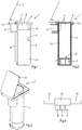
- Figures 1, 2 and 3 show a device 1 by means of which objects such as goods, products, but also for example waste contained in a bag 2 can be brought into a densified or compressed state.
- the bag 2 which in this case is airtight and made of a synthetic resin material, is sealed by closing it, in particular by sealing the synthetic resin bag.
- the device 1 shown is in a vertical position, but may just as well be rotated through 90 degrees, so that the objects contained therein can be moved, which may be desirable in industrial applications.
- products or, for example, waste can be introduced therein, which may be desirable, for example, for use in household application.
- the device 1 comprises a container 3 which is provided with a piston 4 which is movable therein, said piston being shown, in figure 1 , in the topmost position proximate to the input opening 5 of the container. From the top surface 6 of the piston, air ducts 7 extend through the piston 4, which open into the container space 3-1 below the piston 4. Said device 1 also comprises an air pump 8 which opens into the space 3-1, which can be used, inter alia, to create a reduced pressure in said space.
- the bottom of the schematically shown bag 2 is placed on the air ducts 7, after which, in an working mode, the bag is held on the air ducts under the influence of the reduced pressure created in said space 3-1, and if said reduced pressure is large enough, the piston 4 starts to move by itself, together with the bag 2 held on the upper surface, in this case in a downward direction in the container 3 up to the bottom of said container 3, if necessary.
- the airtight bottom of the bag 2 remains fixed on the upper surface 6, and if the air ducts or perforations 7 also extend along the edge of the upper surface 6 of the piston, the bag will remain proximate to the inside wall 9 of the container 3.
- the walls of the bag 2 can be draped over the input opening 5 of the container 3.
- the objects, goods or waste introduced into the container do not contaminate the inside wall 9 of the container 3, which has a favourable effect on the unobstructed motion of the piston 4 in said container.
- the piston 4 is provided with passage means 10 operating the air ducts 7, so that said air ducts 7 only pass air which flows from the upper surface 6 through the piston 4 in a downward direction, then, by pressing air into the space 3-1 below the piston during this working mode, the piston 4 with the bag filled with objects or waste can move upwards by virtue of the compressed air. It is alternatively possible to move the piston 4 upwards by drawing off air above the piston during said working mode. In the latter case, it is sufficient if an air pump 8, which can be used as a suction pump, and which is to be correctly connected to the spaces 3-1 and 3-2 to be evacuated, is made to move up or down around the piston 4.
- this does not require heavy means, and during the upward movement the bottom of the bag 2 remains resting on the upper surface 6, and hence, during this movement, the compressed air cannot escape upwards through the channels 7.
- the bag 2 can be removed from the container 3 if necessary.
- the container 3 has a lid 11 which closes off the upper space 3-2 and which remains closed during the abovementioned upward movement of the piston 4, and the objects and the bag 2 in which they are contained being pressed together and compressed against said lid.
- the air drawn from the spaces 3-1 and 3-2 can be led by the pump 8 through an active carbon filter to the outside air, so that no stench is released into the outside air. If necessary, the bag 2 with content can be subsequently removed and sealed.
- the container 3 has an input opening 5 from which the bag 2 protrudes and at the location of which the container 3 and/or the lid 11 have a sealing unit 12
- the filled, compressed synthetic resin bag 2 can be sealed in an airtight manner. This takes place by folding over the part of the bag 2 extending in the space 3-2 (see fig. 2 ) and sealing it by means of the heat generated by the sealing unit 12. After said sealing operation and after opening the lid 11, the sealed packet of minimal volume can be removed from the container 3.
- the air pump 8 will be coupled to a sensor provided in said space.
- a sensor is arranged to detect the open or closed state of the lid 11.
- the device 1 comprises a control valve 13, shown in fig. 4 , which is connected to the air pump 8, and which is arranged to influence the air pressure in the spaces 3-1 and/or 3-2 above or below the piston 4, it would be possible to make use of the shaft 14 about which the lid 11 pivots. Said shaft 14 can easily extend directly to the shaft 15, shown in figure 4 , which rotates in the valve block, provided with ports A, B and C, of, in this case, the control valve 13.
- the air pump 8 may be a suction/pressure pump, for example a customary vacuum cleaner pump having a pressure side and a suction side, which can be connected in a controlled manner known to those skilled in the art by means of one or more valves to the spaces 3-1 and/or 3-2, in order to perform the abovementioned working modes and piston movements.
- a suction/pressure pump for example a customary vacuum cleaner pump having a pressure side and a suction side, which can be connected in a controlled manner known to those skilled in the art by means of one or more valves to the spaces 3-1 and/or 3-2, in order to perform the abovementioned working modes and piston movements.
- the control valve 13 schematically shown in figure 4 , connects port A, which extends to the suction side of, in this case, a suction pump 8, to either port B or port C in dependence on the position of the shaft 14, 15.
- the reduced pressure on port B or port C is controlled by means of the control valve 13 which is connected to the space 3-1 below the movable piston 4 or the space 3-2 above said movable piston 4.
- a suction pump 8 is sufficient.
- the device 1 is provided with a control unit by means of which the abovementioned working modes of the device 1 are connected.
- the device 1 further comprises an electronic processing unit which is connected to one or more of the following, provided it/they are present in the embodiment in question: the pump, the control valve, the control unit, the sensor coupled to the lid, a motion sensor coupled to the piston, a dynamometer coupled to the lid.
- air pressure and/or piston-position sensors may be used.
- the device 1 may be in the form of a pedal container or pedal bin the lid 11 of which can be operated electronically or by foot.
- the present claims 1 and 7 relate to a method and a device for introducing a bag into a container.
- the method forms a possible first step in the application of a method in which the bag containing objects can be compressed.
Landscapes
- Engineering & Computer Science (AREA)
- Mechanical Engineering (AREA)
- Vacuum Packaging (AREA)
Claims (8)
- Verfahren, bei dem ein luftdichter Beutel (2) auf der oberen Fläche (6) eines Kolbens (4) angeordnet wird, der innerhalb eines Behälters (3) beweglich ist, der durch einen auf demselben bereitgestellten Deckel (11) geschlossen werden kann, wonach ein verringerter Druck unterhalb des Kolbens (4) erzeugt wird, was bewirkt, dass sich der Kolben (4) in dem Behälter (3) nach unten bewegt, und wodurch, wenn sich der Kolben (4) auf Grund eines verringerten Drucks oberhalb des Kolbens (4) herausbewegt, der Beutel (2) mit seinem Inhalt gegen den geschlossenen Deckel (11) zusammengedrückt werden wird, dadurch gekennzeichnet, dass:der Kolben (4) Folgendes umfasst:- Luftkanäle (7), die sich von der oberen Fläche (6) aus durch den Kolben (4) erstrecken, wodurch der verringerte Druck unterhalb des Kolbens (4) ebenfalls bewirkt, dass der Beutel (2) auf dem Kolben (4) gehalten wird, während er sich nach unten bewegt, und- Durchgangsmittel (10), welche die Luftkanäle (7) betätigen, so dass ermöglicht wird, dass, über die Luftkanäle (7), nur Luft hindurchgeht, die von der oberen Fläche (6) durch den Kolben (4) strömt, unddass sich der Kolben (4) unter dem Einfluss eines übermäßigen Drucks unterhalb des Kolbens (4) und/oder des verringerten Drucks oberhalb des Kolbens (4) herausbewegt.
- Verfahren nach Anspruch 1, dadurch gekennzeichnet, dass der Behälter (3) eine Eingabeöffnung (5) hat, an deren Position eine Abdichtungseinheit (12) angeordnet ist, wo der zusammengedrückte Beutel (2) mit Inhalt abgedichtet wird.
- Vorrichtung (1), die Folgendes umfasst:- einen Behälter (3), der einen Kolben (4) umfasst, der innerhalb desselben beweglich ist, wobei der Behälter (3) mit einem Deckel (11) versehen ist, der den Raum (3-2) oberhalb des Kolbens (4) schließt, wobei ein luftdichter Beutel (2) auf der oberen Fläche (6) des Kolbens (4) angeordnet ist,- eine Luftpumpe (8), die mit dem Behälterraum (3-1) unterhalb des Kolbens (4) verbunden ist, um dort einen verringerten Druck zu erzeugen, mit dessen Hilfe der Kolben (4), bewirkt durch den verringerten Druck, dazu veranlasst wird, sich in dem Behälter (3) nach unten zu bewegen, und- ein Steuerventil (13), das mit der Luftpumpe (8) verbunden ist und das dafür angeordnet ist, den Luftdruck in dem Raum (3-1) unterhalb des Kolbens (4) und/oder dem Raum (3-2) oberhalb des Kolbens (4) zu beeinflussen,dadurch gekennzeichnet, dass
die Vorrichtung (1) einen Sensor umfasst, der an die Luftpumpe (8) angeschlossen ist, wobei der Sensor den offenen oder geschlossenen Zustand des Deckels (11) erfasst, und
der Kolben (4) Folgendes umfasst:- Luftkanäle (7), die sich von der oberen Fläche (6) aus durch den Kolben (4) erstrecken, wodurch der verringerte Druck unterhalb des Kolbens (4) ebenfalls bewirkt, dass der Beutel (2) auf dem Kolben (4) gehalten wird, während er sich nach unten bewegt, und- Durchgangsmittel (10), welche die Luftkanäle (7) betätigen, so dass ermöglicht wird, dass, über die Luftkanäle (7), nur Luft hindurchgeht, die von der oberen Fläche (6) durch den Kolben (4) strömt,wodurch sich der Kolben (4) unter dem Einfluss eines übermäßigen Drucks unterhalb des Kolbens (4) und/oder des verringerten Drucks oberhalb des Kolbens (4) herausbewegt, so dass der Beutel (2) mit seinem Inhalt gegen den geschlossenen Deckel (11) zusammengedrückt werden wird. - Vorrichtung (1) nach Anspruch 3, dadurch gekennzeichnet, dass der Deckel (11) um eine Welle (14; 15) schwenkbar ist, die mit dem Steuerventil (13) verbunden ist und deren Drehung das Steuerventil (13) steuert.
- Vorrichtung (1) nach Anspruch 3 oder 4, dadurch gekennzeichnet, dass die Luftpumpe (8) eine Saugpumpe und/oder eine Saug-/Druckpumpe ist.
- Vorrichtung (1) nach einem der Ansprüche 3 bis 5, dadurch gekennzeichnet, dass die Vorrichtung (1) mit einer Steuereinheit versehen ist, mit deren Hilfe Arbeitsmodi der Vorrichtung (1) gesteuert werden.
- Vorrichtung (1) nach einem der Ansprüche 3 bis 6, dadurch gekennzeichnet, dass die Vorrichtung (1) eine elektronische Verarbeitungseinheit umfasst, die, vorausgesetzt, es ist/sie sind vorhanden, mit einem oder mehreren von den Folgenden verbunden ist: der Luftpumpe (8), dem Steuerventil (13), der Steuereinheit, einem an den Deckel (11) angeschlossenen Sensor, einem an den Kolben (4) angeschlossenen Bewegungssensor, einem Deckel (11) angeschlossenen Dynamometer.
- Haushaltsverwendung der Vorrichtung (1) nach einem der Ansprüche 3 bis 7, wobei die Vorrichtung (1) außerdem die Form eines Pedalbehälters oder Pedaleimers hat.
Applications Claiming Priority (1)
| Application Number | Priority Date | Filing Date | Title |
|---|---|---|---|
| NL2013807A NL2013807B1 (nl) | 2014-11-14 | 2014-11-14 | Werkwijze voor het verdichten en sealen van afval. |
Publications (2)
| Publication Number | Publication Date |
|---|---|
| EP3020544A1 EP3020544A1 (de) | 2016-05-18 |
| EP3020544B1 true EP3020544B1 (de) | 2017-07-12 |
Family
ID=52395138
Family Applications (1)
| Application Number | Title | Priority Date | Filing Date |
|---|---|---|---|
| EP15191854.7A Not-in-force EP3020544B1 (de) | 2014-11-14 | 2015-10-28 | Verfahren und vorrichtung zum verdichten und einschliessen von abfall |
Country Status (2)
| Country | Link |
|---|---|
| EP (1) | EP3020544B1 (de) |
| NL (1) | NL2013807B1 (de) |
Families Citing this family (4)
| Publication number | Priority date | Publication date | Assignee | Title |
|---|---|---|---|---|
| CN107521880B (zh) * | 2017-10-10 | 2018-09-11 | 绍兴柯桥勤劳针纺有限公司 | 一种便于使用的卫生间用垃圾桶 |
| CN108557314B (zh) * | 2018-05-21 | 2023-10-03 | 山东大学 | 一种全自动家用智能垃圾桶及其工作方法 |
| CN112550998B (zh) * | 2020-11-17 | 2022-08-30 | 普慧弘义环保技术(北京)有限公司 | 垃圾投放系统 |
| CN114987981B (zh) * | 2022-06-17 | 2023-06-02 | 河海大学 | 一种无臭型智能垃圾投放箱 |
Family Cites Families (6)
| Publication number | Priority date | Publication date | Assignee | Title |
|---|---|---|---|---|
| US3683795A (en) * | 1971-03-10 | 1972-08-15 | Lynn C Harris | Waste compressor |
| WO1988009264A1 (en) * | 1987-05-19 | 1988-12-01 | Myers Holdings Pty. Ltd. | Compaction means |
| ITPD20030164A1 (it) * | 2003-07-17 | 2005-01-18 | Rosolini Ltd | Apparecchiatura per la raccolta e lo smaltimento |
| AU2011262454A1 (en) * | 2010-06-03 | 2013-01-10 | Thomas Falkland Gardiner | Bag holding and sealing apparatus |
| DE202011050997U1 (de) * | 2011-08-16 | 2011-10-13 | Wen-Hsiung Ko | Mülleimer |
| NL2007708C2 (en) * | 2011-11-03 | 2013-05-07 | Craftworks B V | Compactor. |
-
2014
- 2014-11-14 NL NL2013807A patent/NL2013807B1/nl not_active IP Right Cessation
-
2015
- 2015-10-28 EP EP15191854.7A patent/EP3020544B1/de not_active Not-in-force
Non-Patent Citations (1)
| Title |
|---|
| None * |
Also Published As
| Publication number | Publication date |
|---|---|
| NL2013807B1 (nl) | 2016-10-10 |
| EP3020544A1 (de) | 2016-05-18 |
Similar Documents
| Publication | Publication Date | Title |
|---|---|---|
| EP3020544B1 (de) | Verfahren und vorrichtung zum verdichten und einschliessen von abfall | |
| JP3220441U (ja) | インテリジェントごみ箱 | |
| CN110371530B (zh) | 一种智能型多功能厨余垃圾桶 | |
| US20180155073A1 (en) | Vacuum Packaging Machine With Removable Internal And Low-Temperature "Sous Vide" Cooking Chamber | |
| KR102133977B1 (ko) | 악취 누설 방지용 음식물 쓰레기통 | |
| US20140041538A1 (en) | E-Compactor | |
| CN209023537U (zh) | 一种带吹气式套袋结构的垃圾桶 | |
| US7322286B2 (en) | Device for compacting waste in a container, especially a household bin | |
| CN205707522U (zh) | 一种保鲜机 | |
| KR100756543B1 (ko) | 쓰레기 압축장치 | |
| CN201128495Y (zh) | 可真空抽气的包装封口机 | |
| CN110697278A (zh) | 一种真空密封垃圾箱 | |
| KR20130038888A (ko) | 노즐이 구비된 식품용기 진공포장장치 | |
| CN102813476A (zh) | 家用式智能调料柜 | |
| KR101925211B1 (ko) | 가정용 진공포장기. | |
| CN113816036A (zh) | 一种生活垃圾打包装置 | |
| CN108163409A (zh) | 垃圾桶 | |
| KR20180041799A (ko) | 쓰레기통 | |
| CN201672143U (zh) | 密封抽气阀 | |
| CN203473297U (zh) | 一种小型内抽式真空包装机 | |
| JP2023008762A (ja) | バタフライ式ゴミ圧縮装置 | |
| KR101465448B1 (ko) | 커버승강형 식품용기 포장장치 | |
| JP2006218014A (ja) | 流し台装置 | |
| JP3788367B2 (ja) | 分別ごみ減容器 | |
| JP3233954U (ja) | バタフライ式ゴミ圧縮装置 |
Legal Events
| Date | Code | Title | Description |
|---|---|---|---|
| PUAI | Public reference made under article 153(3) epc to a published international application that has entered the european phase |
Free format text: ORIGINAL CODE: 0009012 |
|
| AK | Designated contracting states |
Kind code of ref document: A1 Designated state(s): AL AT BE BG CH CY CZ DE DK EE ES FI FR GB GR HR HU IE IS IT LI LT LU LV MC MK MT NL NO PL PT RO RS SE SI SK SM TR |
|
| AX | Request for extension of the european patent |
Extension state: BA ME |
|
| 17P | Request for examination filed |
Effective date: 20161104 |
|
| RBV | Designated contracting states (corrected) |
Designated state(s): AL AT BE BG CH CY CZ DE DK EE ES FI FR GB GR HR HU IE IS IT LI LT LU LV MC MK MT NL NO PL PT RO RS SE SI SK SM TR |
|
| GRAP | Despatch of communication of intention to grant a patent |
Free format text: ORIGINAL CODE: EPIDOSNIGR1 |
|
| GRAS | Grant fee paid |
Free format text: ORIGINAL CODE: EPIDOSNIGR3 |
|
| INTG | Intention to grant announced |
Effective date: 20170510 |
|
| GRAA | (expected) grant |
Free format text: ORIGINAL CODE: 0009210 |
|
| AK | Designated contracting states |
Kind code of ref document: B1 Designated state(s): AL AT BE BG CH CY CZ DE DK EE ES FI FR GB GR HR HU IE IS IT LI LT LU LV MC MK MT NL NO PL PT RO RS SE SI SK SM TR |
|
| REG | Reference to a national code |
Ref country code: GB Ref legal event code: FG4D |
|
| REG | Reference to a national code |
Ref country code: CH Ref legal event code: EP |
|
| REG | Reference to a national code |
Ref country code: AT Ref legal event code: REF Ref document number: 907938 Country of ref document: AT Kind code of ref document: T Effective date: 20170715 |
|
| REG | Reference to a national code |
Ref country code: IE Ref legal event code: FG4D |
|
| REG | Reference to a national code |
Ref country code: DE Ref legal event code: R096 Ref document number: 602015003538 Country of ref document: DE |
|
| REG | Reference to a national code |
Ref country code: NL Ref legal event code: FP |
|
| REG | Reference to a national code |
Ref country code: FR Ref legal event code: PLFP Year of fee payment: 3 |
|
| REG | Reference to a national code |
Ref country code: LT Ref legal event code: MG4D |
|
| REG | Reference to a national code |
Ref country code: AT Ref legal event code: MK05 Ref document number: 907938 Country of ref document: AT Kind code of ref document: T Effective date: 20170712 |
|
| PG25 | Lapsed in a contracting state [announced via postgrant information from national office to epo] |
Ref country code: AT Free format text: LAPSE BECAUSE OF FAILURE TO SUBMIT A TRANSLATION OF THE DESCRIPTION OR TO PAY THE FEE WITHIN THE PRESCRIBED TIME-LIMIT Effective date: 20170712 Ref country code: SE Free format text: LAPSE BECAUSE OF FAILURE TO SUBMIT A TRANSLATION OF THE DESCRIPTION OR TO PAY THE FEE WITHIN THE PRESCRIBED TIME-LIMIT Effective date: 20170712 Ref country code: NO Free format text: LAPSE BECAUSE OF FAILURE TO SUBMIT A TRANSLATION OF THE DESCRIPTION OR TO PAY THE FEE WITHIN THE PRESCRIBED TIME-LIMIT Effective date: 20171012 Ref country code: FI Free format text: LAPSE BECAUSE OF FAILURE TO SUBMIT A TRANSLATION OF THE DESCRIPTION OR TO PAY THE FEE WITHIN THE PRESCRIBED TIME-LIMIT Effective date: 20170712 Ref country code: LT Free format text: LAPSE BECAUSE OF FAILURE TO SUBMIT A TRANSLATION OF THE DESCRIPTION OR TO PAY THE FEE WITHIN THE PRESCRIBED TIME-LIMIT Effective date: 20170712 Ref country code: HR Free format text: LAPSE BECAUSE OF FAILURE TO SUBMIT A TRANSLATION OF THE DESCRIPTION OR TO PAY THE FEE WITHIN THE PRESCRIBED TIME-LIMIT Effective date: 20170712 |
|
| PG25 | Lapsed in a contracting state [announced via postgrant information from national office to epo] |
Ref country code: PL Free format text: LAPSE BECAUSE OF FAILURE TO SUBMIT A TRANSLATION OF THE DESCRIPTION OR TO PAY THE FEE WITHIN THE PRESCRIBED TIME-LIMIT Effective date: 20170712 Ref country code: RS Free format text: LAPSE BECAUSE OF FAILURE TO SUBMIT A TRANSLATION OF THE DESCRIPTION OR TO PAY THE FEE WITHIN THE PRESCRIBED TIME-LIMIT Effective date: 20170712 Ref country code: ES Free format text: LAPSE BECAUSE OF FAILURE TO SUBMIT A TRANSLATION OF THE DESCRIPTION OR TO PAY THE FEE WITHIN THE PRESCRIBED TIME-LIMIT Effective date: 20170712 Ref country code: BG Free format text: LAPSE BECAUSE OF FAILURE TO SUBMIT A TRANSLATION OF THE DESCRIPTION OR TO PAY THE FEE WITHIN THE PRESCRIBED TIME-LIMIT Effective date: 20171012 Ref country code: LV Free format text: LAPSE BECAUSE OF FAILURE TO SUBMIT A TRANSLATION OF THE DESCRIPTION OR TO PAY THE FEE WITHIN THE PRESCRIBED TIME-LIMIT Effective date: 20170712 Ref country code: IS Free format text: LAPSE BECAUSE OF FAILURE TO SUBMIT A TRANSLATION OF THE DESCRIPTION OR TO PAY THE FEE WITHIN THE PRESCRIBED TIME-LIMIT Effective date: 20171112 Ref country code: GR Free format text: LAPSE BECAUSE OF FAILURE TO SUBMIT A TRANSLATION OF THE DESCRIPTION OR TO PAY THE FEE WITHIN THE PRESCRIBED TIME-LIMIT Effective date: 20171013 |
|
| REG | Reference to a national code |
Ref country code: DE Ref legal event code: R097 Ref document number: 602015003538 Country of ref document: DE |
|
| PG25 | Lapsed in a contracting state [announced via postgrant information from national office to epo] |
Ref country code: CZ Free format text: LAPSE BECAUSE OF FAILURE TO SUBMIT A TRANSLATION OF THE DESCRIPTION OR TO PAY THE FEE WITHIN THE PRESCRIBED TIME-LIMIT Effective date: 20170712 Ref country code: RO Free format text: LAPSE BECAUSE OF FAILURE TO SUBMIT A TRANSLATION OF THE DESCRIPTION OR TO PAY THE FEE WITHIN THE PRESCRIBED TIME-LIMIT Effective date: 20170712 Ref country code: DK Free format text: LAPSE BECAUSE OF FAILURE TO SUBMIT A TRANSLATION OF THE DESCRIPTION OR TO PAY THE FEE WITHIN THE PRESCRIBED TIME-LIMIT Effective date: 20170712 |
|
| PLBE | No opposition filed within time limit |
Free format text: ORIGINAL CODE: 0009261 |
|
| STAA | Information on the status of an ep patent application or granted ep patent |
Free format text: STATUS: NO OPPOSITION FILED WITHIN TIME LIMIT |
|
| PG25 | Lapsed in a contracting state [announced via postgrant information from national office to epo] |
Ref country code: SM Free format text: LAPSE BECAUSE OF FAILURE TO SUBMIT A TRANSLATION OF THE DESCRIPTION OR TO PAY THE FEE WITHIN THE PRESCRIBED TIME-LIMIT Effective date: 20170712 Ref country code: SK Free format text: LAPSE BECAUSE OF FAILURE TO SUBMIT A TRANSLATION OF THE DESCRIPTION OR TO PAY THE FEE WITHIN THE PRESCRIBED TIME-LIMIT Effective date: 20170712 Ref country code: MC Free format text: LAPSE BECAUSE OF FAILURE TO SUBMIT A TRANSLATION OF THE DESCRIPTION OR TO PAY THE FEE WITHIN THE PRESCRIBED TIME-LIMIT Effective date: 20170712 Ref country code: EE Free format text: LAPSE BECAUSE OF FAILURE TO SUBMIT A TRANSLATION OF THE DESCRIPTION OR TO PAY THE FEE WITHIN THE PRESCRIBED TIME-LIMIT Effective date: 20170712 |
|
| 26N | No opposition filed |
Effective date: 20180413 |
|
| REG | Reference to a national code |
Ref country code: IE Ref legal event code: MM4A |
|
| PG25 | Lapsed in a contracting state [announced via postgrant information from national office to epo] |
Ref country code: LU Free format text: LAPSE BECAUSE OF NON-PAYMENT OF DUE FEES Effective date: 20171028 |
|
| PG25 | Lapsed in a contracting state [announced via postgrant information from national office to epo] |
Ref country code: SI Free format text: LAPSE BECAUSE OF FAILURE TO SUBMIT A TRANSLATION OF THE DESCRIPTION OR TO PAY THE FEE WITHIN THE PRESCRIBED TIME-LIMIT Effective date: 20170712 |
|
| PG25 | Lapsed in a contracting state [announced via postgrant information from national office to epo] |
Ref country code: MT Free format text: LAPSE BECAUSE OF NON-PAYMENT OF DUE FEES Effective date: 20171028 |
|
| REG | Reference to a national code |
Ref country code: FR Ref legal event code: PLFP Year of fee payment: 4 |
|
| PG25 | Lapsed in a contracting state [announced via postgrant information from national office to epo] |
Ref country code: IE Free format text: LAPSE BECAUSE OF NON-PAYMENT OF DUE FEES Effective date: 20171028 |
|
| REG | Reference to a national code |
Ref country code: CH Ref legal event code: PL |
|
| PG25 | Lapsed in a contracting state [announced via postgrant information from national office to epo] |
Ref country code: HU Free format text: LAPSE BECAUSE OF FAILURE TO SUBMIT A TRANSLATION OF THE DESCRIPTION OR TO PAY THE FEE WITHIN THE PRESCRIBED TIME-LIMIT; INVALID AB INITIO Effective date: 20151028 |
|
| PG25 | Lapsed in a contracting state [announced via postgrant information from national office to epo] |
Ref country code: CH Free format text: LAPSE BECAUSE OF NON-PAYMENT OF DUE FEES Effective date: 20181031 Ref country code: LI Free format text: LAPSE BECAUSE OF NON-PAYMENT OF DUE FEES Effective date: 20181031 |
|
| PG25 | Lapsed in a contracting state [announced via postgrant information from national office to epo] |
Ref country code: CY Free format text: LAPSE BECAUSE OF FAILURE TO SUBMIT A TRANSLATION OF THE DESCRIPTION OR TO PAY THE FEE WITHIN THE PRESCRIBED TIME-LIMIT Effective date: 20170712 |
|
| PG25 | Lapsed in a contracting state [announced via postgrant information from national office to epo] |
Ref country code: MK Free format text: LAPSE BECAUSE OF FAILURE TO SUBMIT A TRANSLATION OF THE DESCRIPTION OR TO PAY THE FEE WITHIN THE PRESCRIBED TIME-LIMIT Effective date: 20170712 |
|
| PG25 | Lapsed in a contracting state [announced via postgrant information from national office to epo] |
Ref country code: TR Free format text: LAPSE BECAUSE OF FAILURE TO SUBMIT A TRANSLATION OF THE DESCRIPTION OR TO PAY THE FEE WITHIN THE PRESCRIBED TIME-LIMIT Effective date: 20170712 |
|
| PG25 | Lapsed in a contracting state [announced via postgrant information from national office to epo] |
Ref country code: PT Free format text: LAPSE BECAUSE OF FAILURE TO SUBMIT A TRANSLATION OF THE DESCRIPTION OR TO PAY THE FEE WITHIN THE PRESCRIBED TIME-LIMIT Effective date: 20170712 |
|
| PG25 | Lapsed in a contracting state [announced via postgrant information from national office to epo] |
Ref country code: AL Free format text: LAPSE BECAUSE OF FAILURE TO SUBMIT A TRANSLATION OF THE DESCRIPTION OR TO PAY THE FEE WITHIN THE PRESCRIBED TIME-LIMIT Effective date: 20170712 |
|
| PGFP | Annual fee paid to national office [announced via postgrant information from national office to epo] |
Ref country code: NL Payment date: 20201026 Year of fee payment: 6 |
|
| PGFP | Annual fee paid to national office [announced via postgrant information from national office to epo] |
Ref country code: GB Payment date: 20201027 Year of fee payment: 6 Ref country code: FR Payment date: 20201026 Year of fee payment: 6 Ref country code: IT Payment date: 20201023 Year of fee payment: 6 Ref country code: DE Payment date: 20201028 Year of fee payment: 6 |
|
| PGFP | Annual fee paid to national office [announced via postgrant information from national office to epo] |
Ref country code: BE Payment date: 20201027 Year of fee payment: 6 |
|
| REG | Reference to a national code |
Ref country code: DE Ref legal event code: R119 Ref document number: 602015003538 Country of ref document: DE |
|
| REG | Reference to a national code |
Ref country code: NL Ref legal event code: MM Effective date: 20211101 |
|
| REG | Reference to a national code |
Ref country code: BE Ref legal event code: MM Effective date: 20211031 |
|
| GBPC | Gb: european patent ceased through non-payment of renewal fee |
Effective date: 20211028 |
|
| PG25 | Lapsed in a contracting state [announced via postgrant information from national office to epo] |
Ref country code: NL Free format text: LAPSE BECAUSE OF NON-PAYMENT OF DUE FEES Effective date: 20211101 Ref country code: GB Free format text: LAPSE BECAUSE OF NON-PAYMENT OF DUE FEES Effective date: 20211028 Ref country code: DE Free format text: LAPSE BECAUSE OF NON-PAYMENT OF DUE FEES Effective date: 20220503 Ref country code: BE Free format text: LAPSE BECAUSE OF NON-PAYMENT OF DUE FEES Effective date: 20211031 |
|
| PG25 | Lapsed in a contracting state [announced via postgrant information from national office to epo] |
Ref country code: FR Free format text: LAPSE BECAUSE OF NON-PAYMENT OF DUE FEES Effective date: 20211031 |
|
| PG25 | Lapsed in a contracting state [announced via postgrant information from national office to epo] |
Ref country code: IT Free format text: LAPSE BECAUSE OF NON-PAYMENT OF DUE FEES Effective date: 20211028 |