EP3020500B1 - Method for welding dissimilar metals, dissimilar metallic busbar manufactured using same, and secondary battery comprising same - Google Patents
Method for welding dissimilar metals, dissimilar metallic busbar manufactured using same, and secondary battery comprising same Download PDFInfo
- Publication number
- EP3020500B1 EP3020500B1 EP14823627.6A EP14823627A EP3020500B1 EP 3020500 B1 EP3020500 B1 EP 3020500B1 EP 14823627 A EP14823627 A EP 14823627A EP 3020500 B1 EP3020500 B1 EP 3020500B1
- Authority
- EP
- European Patent Office
- Prior art keywords
- metal
- welding
- bus bar
- dissimilar
- laser
- Prior art date
- Legal status (The legal status is an assumption and is not a legal conclusion. Google has not performed a legal analysis and makes no representation as to the accuracy of the status listed.)
- Active
Links
Images


Classifications
-
- B—PERFORMING OPERATIONS; TRANSPORTING
- B23—MACHINE TOOLS; METAL-WORKING NOT OTHERWISE PROVIDED FOR
- B23K—SOLDERING OR UNSOLDERING; WELDING; CLADDING OR PLATING BY SOLDERING OR WELDING; CUTTING BY APPLYING HEAT LOCALLY, e.g. FLAME CUTTING; WORKING BY LASER BEAM
- B23K20/00—Non-electric welding by applying impact or other pressure, with or without the application of heat, e.g. cladding or plating
- B23K20/10—Non-electric welding by applying impact or other pressure, with or without the application of heat, e.g. cladding or plating making use of vibrations, e.g. ultrasonic welding
-
- B—PERFORMING OPERATIONS; TRANSPORTING
- B23—MACHINE TOOLS; METAL-WORKING NOT OTHERWISE PROVIDED FOR
- B23K—SOLDERING OR UNSOLDERING; WELDING; CLADDING OR PLATING BY SOLDERING OR WELDING; CUTTING BY APPLYING HEAT LOCALLY, e.g. FLAME CUTTING; WORKING BY LASER BEAM
- B23K20/00—Non-electric welding by applying impact or other pressure, with or without the application of heat, e.g. cladding or plating
- B23K20/22—Non-electric welding by applying impact or other pressure, with or without the application of heat, e.g. cladding or plating taking account of the properties of the materials to be welded
-
- B—PERFORMING OPERATIONS; TRANSPORTING
- B23—MACHINE TOOLS; METAL-WORKING NOT OTHERWISE PROVIDED FOR
- B23K—SOLDERING OR UNSOLDERING; WELDING; CLADDING OR PLATING BY SOLDERING OR WELDING; CUTTING BY APPLYING HEAT LOCALLY, e.g. FLAME CUTTING; WORKING BY LASER BEAM
- B23K15/00—Electron-beam welding or cutting
-
- B—PERFORMING OPERATIONS; TRANSPORTING
- B23—MACHINE TOOLS; METAL-WORKING NOT OTHERWISE PROVIDED FOR
- B23K—SOLDERING OR UNSOLDERING; WELDING; CLADDING OR PLATING BY SOLDERING OR WELDING; CUTTING BY APPLYING HEAT LOCALLY, e.g. FLAME CUTTING; WORKING BY LASER BEAM
- B23K20/00—Non-electric welding by applying impact or other pressure, with or without the application of heat, e.g. cladding or plating
- B23K20/22—Non-electric welding by applying impact or other pressure, with or without the application of heat, e.g. cladding or plating taking account of the properties of the materials to be welded
- B23K20/233—Non-electric welding by applying impact or other pressure, with or without the application of heat, e.g. cladding or plating taking account of the properties of the materials to be welded without ferrous layer
-
- B—PERFORMING OPERATIONS; TRANSPORTING
- B23—MACHINE TOOLS; METAL-WORKING NOT OTHERWISE PROVIDED FOR
- B23K—SOLDERING OR UNSOLDERING; WELDING; CLADDING OR PLATING BY SOLDERING OR WELDING; CUTTING BY APPLYING HEAT LOCALLY, e.g. FLAME CUTTING; WORKING BY LASER BEAM
- B23K20/00—Non-electric welding by applying impact or other pressure, with or without the application of heat, e.g. cladding or plating
- B23K20/22—Non-electric welding by applying impact or other pressure, with or without the application of heat, e.g. cladding or plating taking account of the properties of the materials to be welded
- B23K20/233—Non-electric welding by applying impact or other pressure, with or without the application of heat, e.g. cladding or plating taking account of the properties of the materials to be welded without ferrous layer
- B23K20/2336—Non-electric welding by applying impact or other pressure, with or without the application of heat, e.g. cladding or plating taking account of the properties of the materials to be welded without ferrous layer both layers being aluminium
-
- B—PERFORMING OPERATIONS; TRANSPORTING
- B23—MACHINE TOOLS; METAL-WORKING NOT OTHERWISE PROVIDED FOR
- B23K—SOLDERING OR UNSOLDERING; WELDING; CLADDING OR PLATING BY SOLDERING OR WELDING; CUTTING BY APPLYING HEAT LOCALLY, e.g. FLAME CUTTING; WORKING BY LASER BEAM
- B23K26/00—Working by laser beam, e.g. welding, cutting or boring
- B23K26/20—Bonding
- B23K26/21—Bonding by welding
- B23K26/22—Spot welding
-
- B—PERFORMING OPERATIONS; TRANSPORTING
- B23—MACHINE TOOLS; METAL-WORKING NOT OTHERWISE PROVIDED FOR
- B23K—SOLDERING OR UNSOLDERING; WELDING; CLADDING OR PLATING BY SOLDERING OR WELDING; CUTTING BY APPLYING HEAT LOCALLY, e.g. FLAME CUTTING; WORKING BY LASER BEAM
- B23K26/00—Working by laser beam, e.g. welding, cutting or boring
- B23K26/20—Bonding
- B23K26/21—Bonding by welding
- B23K26/24—Seam welding
- B23K26/244—Overlap seam welding
-
- B—PERFORMING OPERATIONS; TRANSPORTING
- B23—MACHINE TOOLS; METAL-WORKING NOT OTHERWISE PROVIDED FOR
- B23K—SOLDERING OR UNSOLDERING; WELDING; CLADDING OR PLATING BY SOLDERING OR WELDING; CUTTING BY APPLYING HEAT LOCALLY, e.g. FLAME CUTTING; WORKING BY LASER BEAM
- B23K26/00—Working by laser beam, e.g. welding, cutting or boring
- B23K26/20—Bonding
- B23K26/32—Bonding taking account of the properties of the material involved
-
- B—PERFORMING OPERATIONS; TRANSPORTING
- B23—MACHINE TOOLS; METAL-WORKING NOT OTHERWISE PROVIDED FOR
- B23K—SOLDERING OR UNSOLDERING; WELDING; CLADDING OR PLATING BY SOLDERING OR WELDING; CUTTING BY APPLYING HEAT LOCALLY, e.g. FLAME CUTTING; WORKING BY LASER BEAM
- B23K26/00—Working by laser beam, e.g. welding, cutting or boring
- B23K26/36—Removing material
- B23K26/40—Removing material taking account of the properties of the material involved
-
- B—PERFORMING OPERATIONS; TRANSPORTING
- B23—MACHINE TOOLS; METAL-WORKING NOT OTHERWISE PROVIDED FOR
- B23K—SOLDERING OR UNSOLDERING; WELDING; CLADDING OR PLATING BY SOLDERING OR WELDING; CUTTING BY APPLYING HEAT LOCALLY, e.g. FLAME CUTTING; WORKING BY LASER BEAM
- B23K9/00—Arc welding or cutting
- B23K9/23—Arc welding or cutting taking account of the properties of the materials to be welded
-
- B—PERFORMING OPERATIONS; TRANSPORTING
- B23—MACHINE TOOLS; METAL-WORKING NOT OTHERWISE PROVIDED FOR
- B23K—SOLDERING OR UNSOLDERING; WELDING; CLADDING OR PLATING BY SOLDERING OR WELDING; CUTTING BY APPLYING HEAT LOCALLY, e.g. FLAME CUTTING; WORKING BY LASER BEAM
- B23K2101/00—Articles made by soldering, welding or cutting
- B23K2101/36—Electric or electronic devices
- B23K2101/38—Conductors
-
- B—PERFORMING OPERATIONS; TRANSPORTING
- B23—MACHINE TOOLS; METAL-WORKING NOT OTHERWISE PROVIDED FOR
- B23K—SOLDERING OR UNSOLDERING; WELDING; CLADDING OR PLATING BY SOLDERING OR WELDING; CUTTING BY APPLYING HEAT LOCALLY, e.g. FLAME CUTTING; WORKING BY LASER BEAM
- B23K2103/00—Materials to be soldered, welded or cut
- B23K2103/08—Non-ferrous metals or alloys
- B23K2103/10—Aluminium or alloys thereof
-
- B—PERFORMING OPERATIONS; TRANSPORTING
- B23—MACHINE TOOLS; METAL-WORKING NOT OTHERWISE PROVIDED FOR
- B23K—SOLDERING OR UNSOLDERING; WELDING; CLADDING OR PLATING BY SOLDERING OR WELDING; CUTTING BY APPLYING HEAT LOCALLY, e.g. FLAME CUTTING; WORKING BY LASER BEAM
- B23K2103/00—Materials to be soldered, welded or cut
- B23K2103/08—Non-ferrous metals or alloys
- B23K2103/12—Copper or alloys thereof
-
- B—PERFORMING OPERATIONS; TRANSPORTING
- B23—MACHINE TOOLS; METAL-WORKING NOT OTHERWISE PROVIDED FOR
- B23K—SOLDERING OR UNSOLDERING; WELDING; CLADDING OR PLATING BY SOLDERING OR WELDING; CUTTING BY APPLYING HEAT LOCALLY, e.g. FLAME CUTTING; WORKING BY LASER BEAM
- B23K2103/00—Materials to be soldered, welded or cut
- B23K2103/18—Dissimilar materials
Definitions
- the present invention relates to a method of welding dissimilar metals and a dissimilar metal bus bar manufactured thereby. More particularly, the present invention relates to a method of welding dissimilar metals, wherein any one side of a laminate comprising dissimilar metals is folded and welded, and to a dissimilar metal bus bar manufactured thereby.
- a rechargeable secondary battery is receiving attention as a power source for electric vehicles (EVs), hybrid electric vehicles (HEVs), and plug-in HEVs, which are proposed to overcome air pollution problems of conventional gasoline and diesel vehicles.
- EVs electric vehicles
- HEVs hybrid electric vehicles
- plug-in HEVs plug-in HEVs
- Such a secondary battery is used by electrically connecting a plurality of battery cells.
- the battery cells are connected in such a manner that a bus bar, an anode lead and a cathode lead necessary for electrical connection thereof are linked.
- the conventional welding method using a clad metal requires an additional process for welding between dissimilar metals, undesirably increasing the manufacturing cost and imposing limitations on process convenience. Hence, a method of welding dissimilar metals needs to be improved.
- JP 2002 151045 A relates a battery module mounted as a drive power source in an electric car, a hybrid electric car or the like.
- a bus bar connects a plurality of battery cells in series.
- a positive electrode terminal and a negative electrode terminal are made of different metals.
- the bus bar comprises two metal layers made of the same metal as the positive electrode terminal and the negative electrode terminal, respectively.
- the bus bar is either twisted by 180 ° or bent so as the same metal material of the bus bar is connected to the corresponding electrode terminal.
- JP 2008 084803 A relates to a method of manufacturing a battery.
- a metal housing of the battery is made of aluminum.
- a cover is welded to an opening of the metal housing by means of continuous wave laser welding with a spot diameter of 0.1 to 0.6 mm and a power density of 5 to 33 kW/mm 2 .
- an object of the present invention is to provide a method of welding dissimilar metals, wherein one side of a laminate made up of dissimilar metals is folded so as to enable the welding of the same metals, thereby preventing a welded portion from cracking or corroding with an increase in resistance due to the growth of an intermetallic compound between dissimilar metals, and also an over-lay clad metal may be welded with leads, thus generating economic benefits and improving the convenience of the welding process.
- the present invention provides a method of welding dissimilar metals, as defined in claim 1.
- the present invention provides a dissimilar metal bus as defined in claim 6.
- the present invention provides a lithium secondary battery, comprising the bus bar as above.
- a method of welding dissimilar metals can prevent a welded portion from cracking or corroding with an increase in resistance due to the growth of an intermetallic compound between dissimilar metals. Furthermore, an over-lay clad metal can be welded with leads, thus generating economic benefits and improving the convenience of the welding process.
- a method of welding dissimilar metals comprises: preparing a dissimilar metal bus bar comprising a plate-shaped first member made of a first metal and a plate-shaped second member made of a second metal disposed under the first member; folding one side of the dissimilar metal bus bar so that a portion of the second member is located on a portion of the first member; welding a lead made of the first metal on the first member; and welding a lead made of the second metal to the second member located on the portion of the first member.
- the method of welding dissimilar metals according to the present invention may be applied to welding of various dissimilar metals, especially welding of a laminate structure comprising sequentially stacked dissimilar metals with metal leads made of the dissimilar metals.
- the method of welding dissimilar metals according to the present invention may be applied to the welding of a dissimilar metal bus bar comprising a plate-shaped first member made of a first metal and a plate-shaped second member made of a second metal disposed under the first member with metal leads made of the dissimilar metals.
- the dissimilar metals are not particularly limited, and preferably, the first metal is copper and the second metal is aluminum.
- the dissimilar metal bus bar comprising the plate-shaped first member made of the first metal and the plate-shaped second member made of the second metal disposed under the first member may be provided in the form of a clad metal.
- the clad metal may be an in-lay clad metal or an over-lay clad metal.
- Preferably useful is an over-lay clad metal.
- one side of the dissimilar metal bus bar is folded so that a portion of the second member is located on a portion of the plate-shaped first member made of the first metal.
- the first member made of the first metal and the lead made of the first metal may be directly welded
- the second member made of the second metal and the lead made of the second metal may be directly welded.
- a width of the portion of the second member located on the portion of the first member is equal to or greater than a welding width of the dissimilar metal bus bar and is equal to or less than the width of a welding jig. If the width thereof is less than the welding width, a welding area may decrease and thus bondability may deteriorate. In contrast, if the width thereof is greater than the width of the welding jig, the amount of metal used may be increased, undesirably enlarging the size of the bus bar.
- a dissimilar metal bus bar comprising a plate-shaped first member made of a first metal and a plate-shaped second member made of a second metal disposed under the first member includes a folded portion formed by folding one side of the dissimilar metal bus bar so that a portion of the second member is located on a portion of the first member, and a lead made of the first metal is welded on the first member, and a lead made of the second metal is welded to the second member, wherein the welding of the respective lead to the first member and the second member is performed according to the methods claimed in claims 1-5.
- the first metal may be copper and the second metal may be aluminum.
- the dissimilar metal bus bar configured such that the plate-shaped second member made of the second metal is disposed under the plate-shaped first member made of the first metal may be provided in the form of a clad metal.
- the clad metal may be an in-lay clad metal or an over-lay clad metal.
- Preferably useful is an over-lay clad metal.
- the dissimilar metal bus bar according to the present invention includes a folded portion formed by folding one side of the dissimilar metal bus bar so that the second member is located on a portion of the plate-shaped first member made of the first metal.
- a folded portion formed by folding one side of the dissimilar metal bus bar so that the second member is located on a portion of the plate-shaped first member made of the first metal.
- a width of the portion of the second member located on the portion of the first member is equal to or greater than a welding width of the dissimilar metal bus bar and is equal to or less than the width of a welding jig. If the width thereof is less than the welding width, a welding area may become small and thus poor bondability may result. In contrast, if the width thereof is greater than the width of the welding jig, the metal may be used in an increased amount, and thus the size of the bus bar may become large.
- Laser welding is performed at a welding rate of 50 ⁇ 200 mm/s using a continuous wave (CW) laser having a laser energy density of 150 ⁇ 650 kJ/cm 2 and an optical system.
- CW continuous wave
- laser welding is carried out at a welding rate of 80 ⁇ 120 mm/s using a CW laser having a laser energy density of 300 ⁇ 550 kJ/cm 2 and an optical system.
- laser oscillation may be modulated to a predetermined frequency in order to prevent thermal damage to the welding material due to continuous exposure to heat.
- a modulation frequency may be 8 Hz ⁇ 5 kHz, and laser oscillation upon modulation may correspond to 30 ⁇ 90% of the modulation frequency.
- 50% oscillation is used for 1 kHz modulation
- laser output modulation at an interval of 1 ms is conducted, which means that 500 us corresponding to a laser oscillation state and 500 us corresponding to no laser oscillation state are repeated.
- a lithium secondary battery includes the dissimilar metal bus bar as above, and thereby a plurality of battery cells, which are electrically connected, may be used, thus exhibiting superior bondability and reducing the generation of an intermetallic compound between dissimilar metals, ultimately decreasing corrosion or cracking.
- one side of an over-lay clad metal configured such that an aluminum plate was disposed under a copper plate was folded, after which an aluminum lead was located on the aluminum position, and a copper lead was located on the copper position, followed by welding at a welding rate of 100 mm/s using a CW laser (a modulation frequency of 1 kHz, 50% output of the modulation frequency) having a laser energy density of 400 ⁇ 500 kJ/cm 2 and an optical system.
- a CW laser a modulation frequency of 1 kHz, 50% output of the modulation frequency
- an aluminum lead and a copper lead were located on both ends of a copper plate, and then individually welded at a welding rate of 100 mm/s using a CW laser (a modulation frequency of 1 kHz, 50% output of the modulation frequency) having a laser energy density of 400 ⁇ 500 kJ/cm 2 and an optical system.
- a CW laser a modulation frequency of 1 kHz, 50% output of the modulation frequency
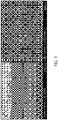
- Example 1 The surface of the welded bus bars of Example 1 and Comparative Example 1 was observed using a scanning electron microscope (SEM). As illustrated in FIG. 3 , the dissimilar metal compound was produced upon welding of the copper bus bar. However, as illustrated in FIG. 4 , the laser welding of the clad metal bus bar did not produce the dissimilar metal compound.
- SEM scanning electron microscope
- Test Example 2 Tensile strength and salt spray corrosion testing
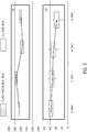
- the tensile strength of the welded bus bars of Example 1 and Comparative Example 1 was measured. The results are shown in FIG. 5 . As illustrated in FIG. 5 , when the clad metal bus bar was subjected to laser welding, it had a tensile strength of 160 Kgf or more, which was much higher than 60 Kgf of the welded copper bus bar.
Landscapes
- Engineering & Computer Science (AREA)
- Mechanical Engineering (AREA)
- Physics & Mathematics (AREA)
- Optics & Photonics (AREA)
- Plasma & Fusion (AREA)
- Chemical & Material Sciences (AREA)
- Materials Engineering (AREA)
- Connection Of Batteries Or Terminals (AREA)
- Laser Beam Processing (AREA)
Description
- The present invention relates to a method of welding dissimilar metals and a dissimilar metal bus bar manufactured thereby. More particularly, the present invention relates to a method of welding dissimilar metals, wherein any one side of a laminate comprising dissimilar metals is folded and welded, and to a dissimilar metal bus bar manufactured thereby.
- A rechargeable secondary battery is receiving attention as a power source for electric vehicles (EVs), hybrid electric vehicles (HEVs), and plug-in HEVs, which are proposed to overcome air pollution problems of conventional gasoline and diesel vehicles.
- Such a secondary battery is used by electrically connecting a plurality of battery cells. As such, the battery cells are connected in such a manner that a bus bar, an anode lead and a cathode lead necessary for electrical connection thereof are linked.
- However, when anode and cathode leads made of dissimilar metals are welded to the bus bar, an intermetallic compound between dissimilar metals may be formed, and thus brittleness may increase, undesirably increasing the risk of cracking. Furthermore, when changes in temperature and environment continuously occur, the intermetallic compound between dissimilar metals may grow, whereby the welded portion may crack or may corrode with an increase in resistance. To solve such problems, mainly utilized is a method of connecting the dissimilar metal bus bar and the leads made of dissimilar metals using a clad metal formed by pressure welding. Such a welding method using a clad metal is disclosed in Korean Patent Application Publication No.
10-2011-0109779 - However, the conventional welding method using a clad metal requires an additional process for welding between dissimilar metals, undesirably increasing the manufacturing cost and imposing limitations on process convenience. Hence, a method of welding dissimilar metals needs to be improved.
-
JP 2002 151045 A -
JP 2008 084803 A - The present invention has been made keeping in mind the above problems encountered in the related art, and an object of the present invention is to provide a method of welding dissimilar metals, wherein one side of a laminate made up of dissimilar metals is folded so as to enable the welding of the same metals, thereby preventing a welded portion from cracking or corroding with an increase in resistance due to the growth of an intermetallic compound between dissimilar metals, and also an over-lay clad metal may be welded with leads, thus generating economic benefits and improving the convenience of the welding process.
- In order to accomplish the above objects, the present invention provides a method of welding dissimilar metals, as defined in claim 1.
- In addition, the present invention provides a dissimilar metal bus as defined in
claim 6. - In addition, the present invention provides a lithium secondary battery, comprising the bus bar as above.
- According to the present invention, a method of welding dissimilar metals can prevent a welded portion from cracking or corroding with an increase in resistance due to the growth of an intermetallic compound between dissimilar metals. Furthermore, an over-lay clad metal can be welded with leads, thus generating economic benefits and improving the convenience of the welding process.
-
-
FIG. 1 schematically illustrates a conventional process of welding dissimilar metals; and -
FIG. 2 schematically illustrates a process of welding dissimilar metals according to the present invention. - Hereinafter, a detailed description will be given of the present invention.
- According to the present invention, a method of welding dissimilar metals comprises: preparing a dissimilar metal bus bar comprising a plate-shaped first member made of a first metal and a plate-shaped second member made of a second metal disposed under the first member; folding one side of the dissimilar metal bus bar so that a portion of the second member is located on a portion of the first member; welding a lead made of the first metal on the first member; and welding a lead made of the second metal to the second member located on the portion of the first member.
- The method of welding dissimilar metals according to the present invention may be applied to welding of various dissimilar metals, especially welding of a laminate structure comprising sequentially stacked dissimilar metals with metal leads made of the dissimilar metals. Specifically, the method of welding dissimilar metals according to the present invention may be applied to the welding of a dissimilar metal bus bar comprising a plate-shaped first member made of a first metal and a plate-shaped second member made of a second metal disposed under the first member with metal leads made of the dissimilar metals.
- The dissimilar metals are not particularly limited, and preferably, the first metal is copper and the second metal is aluminum.
- In the present invention, the dissimilar metal bus bar comprising the plate-shaped first member made of the first metal and the plate-shaped second member made of the second metal disposed under the first member may be provided in the form of a clad metal. The clad metal may be an in-lay clad metal or an over-lay clad metal. Preferably useful is an over-lay clad metal.
- In the method of welding dissimilar metals according to the present invention, as illustrated in
FIG. 2 , one side of the dissimilar metal bus bar is folded so that a portion of the second member is located on a portion of the plate-shaped first member made of the first metal. When one side of the bus bar is folded in this way, the first member made of the first metal and the lead made of the first metal may be directly welded, and the second member made of the second metal and the lead made of the second metal may be directly welded. Hence, the formation of an intermetallic compound due to the welding of dissimilar metals may be prevented, and thus cracking due to increased brittleness may be remarkably reduced. As mentioned above, when one side of the dissimilar metal bus bar is folded so that the second member is located on a portion of the plate-shaped first member made of the first metal, a width of the portion of the second member located on the portion of the first member is equal to or greater than a welding width of the dissimilar metal bus bar and is equal to or less than the width of a welding jig. If the width thereof is less than the welding width, a welding area may decrease and thus bondability may deteriorate. In contrast, if the width thereof is greater than the width of the welding jig, the amount of metal used may be increased, undesirably enlarging the size of the bus bar. - The method of welding dissimilar metals according to the present invention, is defined in claim 1.
- According to the present invention, a dissimilar metal bus bar comprising a plate-shaped first member made of a first metal and a plate-shaped second member made of a second metal disposed under the first member includes a folded portion formed by folding one side of the dissimilar metal bus bar so that a portion of the second member is located on a portion of the first member, and a lead made of the first metal is welded on the first member, and a lead made of the second metal is welded to the second member, wherein the welding of the respective lead to the first member and the second member is performed according to the methods claimed in claims 1-5.
- Although the dissimilar metals are not particularly limited, the first metal may be copper and the second metal may be aluminum.
- In the present invention, the dissimilar metal bus bar configured such that the plate-shaped second member made of the second metal is disposed under the plate-shaped first member made of the first metal may be provided in the form of a clad metal. As such, the clad metal may be an in-lay clad metal or an over-lay clad metal. Preferably useful is an over-lay clad metal.
- As illustrated in
FIG. 2 , the dissimilar metal bus bar according to the present invention includes a folded portion formed by folding one side of the dissimilar metal bus bar so that the second member is located on a portion of the plate-shaped first member made of the first metal. When one side of the bus bar is folded in this way, it is possible to directly weld the first member made of the first metal and the lead made of the first metal, and also to directly weld the second member made of the second metal and the lead made of the second metal, thereby preventing the formation of an intermetallic compound due to the welding of dissimilar metals, ultimately considerably reducing the generation of cracking attributed to increased brittleness. As mentioned above, when the second member is located on a portion of the plate-shaped first member made of the first metal by folding one side of the dissimilar metal bus bar, a width of the portion of the second member located on the portion of the first member is equal to or greater than a welding width of the dissimilar metal bus bar and is equal to or less than the width of a welding jig. If the width thereof is less than the welding width, a welding area may become small and thus poor bondability may result. In contrast, if the width thereof is greater than the width of the welding jig, the metal may be used in an increased amount, and thus the size of the bus bar may become large. - Laser welding is performed at a welding rate of 50 ∼ 200 mm/s using a continuous wave (CW) laser having a laser energy density of 150 ∼ 650 kJ/cm2 and an optical system. Preferably, laser welding is carried out at a welding rate of 80 ∼ 120 mm/s using a CW laser having a laser energy density of 300 ∼ 550 kJ/cm2 and an optical system.
- Furthermore, laser oscillation may be modulated to a predetermined frequency in order to prevent thermal damage to the welding material due to continuous exposure to heat. As such, a modulation frequency may be 8 Hz ∼ 5 kHz, and laser oscillation upon modulation may correspond to 30 ∼ 90% of the modulation frequency. For example, when 50% oscillation is used for 1 kHz modulation, laser output modulation at an interval of 1 ms is conducted, which means that 500 us corresponding to a laser oscillation state and 500 us corresponding to no laser oscillation state are repeated.
- According to the present invention, a lithium secondary battery includes the dissimilar metal bus bar as above, and thereby a plurality of battery cells, which are electrically connected, may be used, thus exhibiting superior bondability and reducing the generation of an intermetallic compound between dissimilar metals, ultimately decreasing corrosion or cracking.
- The following examples of the present invention are disclosed for illustrative purposes.
- As illustrated in
FIG. 2 , one side of an over-lay clad metal configured such that an aluminum plate was disposed under a copper plate was folded, after which an aluminum lead was located on the aluminum position, and a copper lead was located on the copper position, followed by welding at a welding rate of 100 mm/s using a CW laser (a modulation frequency of 1 kHz, 50% output of the modulation frequency) having a laser energy density of 400 ∼ 500 kJ/cm2 and an optical system. - As illustrated in
FIG. 1 , an aluminum lead and a copper lead were located on both ends of a copper plate, and then individually welded at a welding rate of 100 mm/s using a CW laser (a modulation frequency of 1 kHz, 50% output of the modulation frequency) having a laser energy density of 400 ∼ 500 kJ/cm2 and an optical system. - The surface of the welded bus bars of Example 1 and Comparative Example 1 was observed using a scanning electron microscope (SEM). As illustrated in
FIG. 3 , the dissimilar metal compound was produced upon welding of the copper bus bar. However, as illustrated inFIG. 4 , the laser welding of the clad metal bus bar did not produce the dissimilar metal compound. - The tensile strength of the welded bus bars of Example 1 and Comparative Example 1 was measured. The results are shown in
FIG. 5 . As illustrated inFIG. 5 , when the clad metal bus bar was subjected to laser welding, it had a tensile strength of 160 Kgf or more, which was much higher than 60 Kgf of the welded copper bus bar. - Furthermore, 0.6 mol salt spray corrosion testing was performed. Changes in welding strength over time are illustrated in
FIG. 5 . As illustrated inFIG. 5 , changes in tensile strength over time were significant in the copper bus bar but were insignificant in the clad metal bus bar.
Claims (10)
- A method of welding dissimilar metals, comprising:preparing a dissimilar metal bus bar comprising a plate-shaped first member made of a first metal and a plate-shaped second member made of a second metal disposed under the first member;folding one side of the dissimilar metal bus bar so that a portion of the second member is located on a portion of the first member;welding a lead made of the first metal on the first member; andwelding a lead made of the second metal to the second member located on the portion of the first member,wherein the welding is performed using laser welding,wherein the laser welding is performed at a welding rate of 50 to 200 mm/s using a continuous wave (CW) laser having a laser energy density of 150 to 650 kJ/cm2 and an optical system.
- The method of claim 1, wherein the first metal is copper, and the second metal is aluminum.
- The method of claim i, wherein the dissimilar metal bus bar comprises a clad metal.
- The method of claim 3, wherein the clad metal is an over-lay clad metal.
- The method of claim 1, wherein the CW laser has a modulation frequency of 8 Hz - 5 kHz, and is oscillated at 30 - 90% of the modulation frequency.
- A dissimilar metal bus bar comprising a plate-shaped first member made of a first metal and a plate-shaped second member made of a second metal disposed under the first member,
wherein the dissimilar metal bus bar includes a folded portion formed by folding one side of the dissimilar metal bus bar so that a portion of the second member is located on a portion of the first member,
a lead made of the first metal is welded on the first member, and
a lead made of the second metal is welded to the second member,
wherein the welding of the respective lead to the first member and the second member is performed according to the method of any of the preceding claims . - The dissimilar metal bus bar of claim 6, wherein the first metal is copper, and the second metal is aluminum.
- The dissimilar metal bus bar of claim 6, wherein the dissimilar metal bus bar comprises a clad metal.
- The dissimilar metal bus bar of claim 8, wherein the clad metal is an over-lay clad metal.
- A lithium secondary battery, comprising the bus bar of claim 6.
Applications Claiming Priority (3)
| Application Number | Priority Date | Filing Date | Title |
|---|---|---|---|
| KR20130080449 | 2013-07-09 | ||
| KR1020140085445A KR101554361B1 (en) | 2013-07-09 | 2014-07-08 | A welding method of different metal, different metal busbar manufactured by the same and secondary battery comprising the same |
| PCT/KR2014/006164 WO2015005676A1 (en) | 2013-07-09 | 2014-07-09 | Method for welding dissimilar metals, dissimilar metallic busbar manufactured using same, and secondary battery comprising same |
Publications (3)
| Publication Number | Publication Date |
|---|---|
| EP3020500A1 EP3020500A1 (en) | 2016-05-18 |
| EP3020500A4 EP3020500A4 (en) | 2016-07-20 |
| EP3020500B1 true EP3020500B1 (en) | 2020-01-15 |
Family
ID=52570270
Family Applications (1)
| Application Number | Title | Priority Date | Filing Date |
|---|---|---|---|
| EP14823627.6A Active EP3020500B1 (en) | 2013-07-09 | 2014-07-09 | Method for welding dissimilar metals, dissimilar metallic busbar manufactured using same, and secondary battery comprising same |
Country Status (5)
| Country | Link |
|---|---|
| US (1) | US10350702B2 (en) |
| EP (1) | EP3020500B1 (en) |
| KR (1) | KR101554361B1 (en) |
| CN (1) | CN105358287A (en) |
| WO (1) | WO2015005676A1 (en) |
Families Citing this family (11)
| Publication number | Priority date | Publication date | Assignee | Title |
|---|---|---|---|---|
| JP6610269B2 (en) * | 2016-01-08 | 2019-11-27 | 住友金属鉱山株式会社 | Conductor on electrolytic cell made of composite material of different metals and manufacturing method thereof |
| KR20210134087A (en) * | 2016-04-29 | 2021-11-08 | 누부루 인크. | Visible laser welding of electronic packaging, automotive electrics, battery and other components |
| US10243191B2 (en) * | 2016-07-21 | 2019-03-26 | Ford Global Technologies, Llc | Flexible multi-layered bus bar |
| KR102299768B1 (en) | 2017-09-11 | 2021-09-07 | 주식회사 엘지화학 | Method for laser welding of different metals with optimization of welding condition by using intermetallic compound analysis |
| EP3480868B1 (en) | 2017-11-03 | 2025-06-25 | Greatbatch Ltd. | Laser brazed component and method therefor |
| US12283720B2 (en) * | 2019-03-12 | 2025-04-22 | Vehicle Energy Japan Inc. | Bus bar, and battery module using same |
| KR102722633B1 (en) * | 2019-03-26 | 2024-10-25 | 주식회사 엘지에너지솔루션 | Busbar module and method of manufacturing the same |
| KR102819127B1 (en) * | 2020-03-31 | 2025-06-12 | 주식회사 엘지에너지솔루션 | High Voltage Busbar Having Dissimilar Metals and Manufacturing Method Thereof |
| WO2021263135A1 (en) | 2020-06-25 | 2021-12-30 | Medtronic, Inc. | Shaped rechargeable battery electronic interconnect |
| US12145517B2 (en) | 2021-10-28 | 2024-11-19 | Our Next Energy, Inc. | Flexible aluminum busbar |
| DE102024114988A1 (en) * | 2024-05-28 | 2025-12-04 | PULSETRAIN GmbH | Welding process |
Citations (2)
| Publication number | Priority date | Publication date | Assignee | Title |
|---|---|---|---|---|
| US5027360A (en) * | 1990-06-13 | 1991-06-25 | Stanford University | High power continuous wave injection-locked solid state laser |
| JP2008084803A (en) * | 2006-09-29 | 2008-04-10 | Sanyo Electric Co Ltd | Manufacturing method of sealed battery |
Family Cites Families (12)
| Publication number | Priority date | Publication date | Assignee | Title |
|---|---|---|---|---|
| US3402254A (en) * | 1966-12-02 | 1968-09-17 | Texas Instruments Inc | Composite electrical bus bar |
| US5942314A (en) | 1997-04-17 | 1999-08-24 | Mitsui Mining & Smelting Co., Ltd. | Ultrasonic welding of copper foil |
| JP2002151045A (en) * | 2000-11-10 | 2002-05-24 | Honda Motor Co Ltd | Bus bar for battery module and battery module |
| JP2005288481A (en) * | 2004-03-31 | 2005-10-20 | Shibaura Mechatronics Corp | Laser welding method for highly reflective members |
| US7301123B2 (en) * | 2004-04-29 | 2007-11-27 | U.I.T., L.L.C. | Method for modifying or producing materials and joints with specific properties by generating and applying adaptive impulses a normalizing energy thereof and pauses therebetween |
| US9590000B2 (en) * | 2009-12-14 | 2017-03-07 | Shilat Optical Systems Ltd. | Laser daylight designation and pointing |
| CN102208591B (en) * | 2010-03-30 | 2015-03-25 | 三星Sdi株式会社 | Secondary battery and secondary battery module |
| US8956753B2 (en) | 2010-03-30 | 2015-02-17 | Samsung Sdi Co., Ltd. | Secondary battery and secondary battery module |
| KR101217073B1 (en) | 2010-03-30 | 2012-12-31 | 로베르트 보쉬 게엠베하 | Secondary battery and secondary battery module |
| JP5186528B2 (en) | 2010-04-23 | 2013-04-17 | 日本発條株式会社 | Conductive member and manufacturing method thereof |
| WO2013094000A1 (en) * | 2011-12-19 | 2013-06-27 | 日立ビークルエナジー株式会社 | Welded structure in battery, method for forming same, secondary battery cell, and secondary battery module |
| JP2014094386A (en) | 2012-11-08 | 2014-05-22 | Hitachi Automotive Systems Ltd | Method of joining dissimilar metal bus bars, and dissimilar metal bus bar, and electric power conversion equipment using the same |
-
2014
- 2014-07-08 KR KR1020140085445A patent/KR101554361B1/en active Active
- 2014-07-09 EP EP14823627.6A patent/EP3020500B1/en active Active
- 2014-07-09 WO PCT/KR2014/006164 patent/WO2015005676A1/en not_active Ceased
- 2014-07-09 US US14/903,027 patent/US10350702B2/en active Active
- 2014-07-09 CN CN201480039039.2A patent/CN105358287A/en active Pending
Patent Citations (2)
| Publication number | Priority date | Publication date | Assignee | Title |
|---|---|---|---|---|
| US5027360A (en) * | 1990-06-13 | 1991-06-25 | Stanford University | High power continuous wave injection-locked solid state laser |
| JP2008084803A (en) * | 2006-09-29 | 2008-04-10 | Sanyo Electric Co Ltd | Manufacturing method of sealed battery |
Also Published As
| Publication number | Publication date |
|---|---|
| US10350702B2 (en) | 2019-07-16 |
| KR101554361B1 (en) | 2015-09-18 |
| CN105358287A (en) | 2016-02-24 |
| EP3020500A4 (en) | 2016-07-20 |
| EP3020500A1 (en) | 2016-05-18 |
| WO2015005676A1 (en) | 2015-01-15 |
| KR20150007242A (en) | 2015-01-20 |
| US20160151853A1 (en) | 2016-06-02 |
Similar Documents
| Publication | Publication Date | Title |
|---|---|---|
| US10350702B2 (en) | Method for welding dissimilar metals, dissimilar metallic busbar manufactured using same, and secondary battery comprising same | |
| KR100878700B1 (en) | Electrode plate for battery cell production and its manufacturing method | |
| KR101629480B1 (en) | Battery Module Comprising Connecting Member Composed of Dissimilar Metals | |
| KR20130049984A (en) | Bus bar for battery and battery module | |
| CN101335340A (en) | Sealed battery and method for manufacturing same | |
| US7943253B2 (en) | Sealed battery and manufacturing method therefor | |
| WO2017068976A1 (en) | Wiring module, detection terminal, and method for producing detection terminal | |
| US20020164524A1 (en) | Lithium secondary cell | |
| CN105679991A (en) | Composite pole and battery module with same | |
| US20250372827A1 (en) | Metal welded structure, battery pack using same, and battery pack production method | |
| JP5957651B2 (en) | Assembled battery | |
| US20230344087A1 (en) | Busbar and battery pack including the same | |
| CN110571400A (en) | power battery module bus bar and welding method thereof | |
| CN106558673A (en) | Rectangular secondary cell | |
| CN205723728U (en) | Battery pack and battery pack having the same | |
| CN206685496U (en) | A kind of lead-acid starter battery | |
| US20220190421A1 (en) | Power supply device and electric vehicle and power storage device using same, fastening member for power supply device, production method for power supply device, and production method for fastening member for power supply device | |
| US20170207490A1 (en) | Method for Producing a Prismatic Battery Cell | |
| CN211125802U (en) | Power battery module busbar | |
| CN210052783U (en) | Homonymy collection flow structure, battery module and electric motor car | |
| US20160315305A1 (en) | Preconditioned Bus Bar Interconnect System | |
| JP7844396B2 (en) | Energy storage module | |
| CN119944243A (en) | Battery module and method of manufacturing the same |
Legal Events
| Date | Code | Title | Description |
|---|---|---|---|
| PUAI | Public reference made under article 153(3) epc to a published international application that has entered the european phase |
Free format text: ORIGINAL CODE: 0009012 |
|
| 17P | Request for examination filed |
Effective date: 20151229 |
|
| AK | Designated contracting states |
Kind code of ref document: A1 Designated state(s): AL AT BE BG CH CY CZ DE DK EE ES FI FR GB GR HR HU IE IS IT LI LT LU LV MC MK MT NL NO PL PT RO RS SE SI SK SM TR |
|
| AX | Request for extension of the european patent |
Extension state: BA ME |
|
| A4 | Supplementary search report drawn up and despatched |
Effective date: 20160617 |
|
| RIC1 | Information provided on ipc code assigned before grant |
Ipc: B23K 26/244 20140101ALI20160613BHEP Ipc: B23K 20/22 20060101AFI20160613BHEP Ipc: B23K 103/12 20060101ALI20160613BHEP Ipc: B23K 20/10 20060101ALI20160613BHEP Ipc: B23K 9/23 20060101ALI20160613BHEP Ipc: B23K 26/22 20060101ALI20160613BHEP Ipc: B23K 101/38 20060101ALI20160613BHEP Ipc: B23K 20/233 20060101ALI20160613BHEP Ipc: B23K 103/10 20060101ALI20160613BHEP Ipc: B23K 26/00 20140101ALI20160613BHEP Ipc: B23K 15/00 20060101ALI20160613BHEP Ipc: B23K 26/32 20140101ALI20160613BHEP |
|
| DAX | Request for extension of the european patent (deleted) | ||
| STAA | Information on the status of an ep patent application or granted ep patent |
Free format text: STATUS: EXAMINATION IS IN PROGRESS |
|
| 17Q | First examination report despatched |
Effective date: 20190222 |
|
| GRAP | Despatch of communication of intention to grant a patent |
Free format text: ORIGINAL CODE: EPIDOSNIGR1 |
|
| STAA | Information on the status of an ep patent application or granted ep patent |
Free format text: STATUS: GRANT OF PATENT IS INTENDED |
|
| RIC1 | Information provided on ipc code assigned before grant |
Ipc: B23K 103/12 20060101ALI20190904BHEP Ipc: B23K 20/10 20060101ALI20190904BHEP Ipc: B23K 20/22 20060101AFI20190904BHEP Ipc: B23K 9/23 20060101ALI20190904BHEP Ipc: B23K 101/38 20060101ALI20190904BHEP Ipc: B23K 20/233 20060101ALI20190904BHEP Ipc: B23K 103/10 20060101ALI20190904BHEP Ipc: B23K 15/00 20060101ALI20190904BHEP Ipc: B23K 103/18 20060101ALI20190904BHEP Ipc: B23K 26/32 20140101ALI20190904BHEP Ipc: B23K 26/244 20140101ALI20190904BHEP Ipc: B23K 26/00 20140101ALI20190904BHEP Ipc: B23K 26/22 20060101ALI20190904BHEP |
|
| INTG | Intention to grant announced |
Effective date: 20190930 |
|
| GRAS | Grant fee paid |
Free format text: ORIGINAL CODE: EPIDOSNIGR3 |
|
| GRAA | (expected) grant |
Free format text: ORIGINAL CODE: 0009210 |
|
| STAA | Information on the status of an ep patent application or granted ep patent |
Free format text: STATUS: THE PATENT HAS BEEN GRANTED |
|
| AK | Designated contracting states |
Kind code of ref document: B1 Designated state(s): AL AT BE BG CH CY CZ DE DK EE ES FI FR GB GR HR HU IE IS IT LI LT LU LV MC MK MT NL NO PL PT RO RS SE SI SK SM TR |
|
| REG | Reference to a national code |
Ref country code: CH Ref legal event code: EP Ref country code: GB Ref legal event code: FG4D |
|
| REG | Reference to a national code |
Ref country code: IE Ref legal event code: FG4D |
|
| REG | Reference to a national code |
Ref country code: DE Ref legal event code: R096 Ref document number: 602014060136 Country of ref document: DE |
|
| REG | Reference to a national code |
Ref country code: AT Ref legal event code: REF Ref document number: 1224725 Country of ref document: AT Kind code of ref document: T Effective date: 20200215 |
|
| REG | Reference to a national code |
Ref country code: NL Ref legal event code: MP Effective date: 20200115 |
|
| REG | Reference to a national code |
Ref country code: LT Ref legal event code: MG4D |
|
| PG25 | Lapsed in a contracting state [announced via postgrant information from national office to epo] |
Ref country code: NL Free format text: LAPSE BECAUSE OF FAILURE TO SUBMIT A TRANSLATION OF THE DESCRIPTION OR TO PAY THE FEE WITHIN THE PRESCRIBED TIME-LIMIT Effective date: 20200115 Ref country code: PT Free format text: LAPSE BECAUSE OF FAILURE TO SUBMIT A TRANSLATION OF THE DESCRIPTION OR TO PAY THE FEE WITHIN THE PRESCRIBED TIME-LIMIT Effective date: 20200607 Ref country code: NO Free format text: LAPSE BECAUSE OF FAILURE TO SUBMIT A TRANSLATION OF THE DESCRIPTION OR TO PAY THE FEE WITHIN THE PRESCRIBED TIME-LIMIT Effective date: 20200415 Ref country code: FI Free format text: LAPSE BECAUSE OF FAILURE TO SUBMIT A TRANSLATION OF THE DESCRIPTION OR TO PAY THE FEE WITHIN THE PRESCRIBED TIME-LIMIT Effective date: 20200115 Ref country code: RS Free format text: LAPSE BECAUSE OF FAILURE TO SUBMIT A TRANSLATION OF THE DESCRIPTION OR TO PAY THE FEE WITHIN THE PRESCRIBED TIME-LIMIT Effective date: 20200115 |
|
| PG25 | Lapsed in a contracting state [announced via postgrant information from national office to epo] |
Ref country code: LV Free format text: LAPSE BECAUSE OF FAILURE TO SUBMIT A TRANSLATION OF THE DESCRIPTION OR TO PAY THE FEE WITHIN THE PRESCRIBED TIME-LIMIT Effective date: 20200115 Ref country code: SE Free format text: LAPSE BECAUSE OF FAILURE TO SUBMIT A TRANSLATION OF THE DESCRIPTION OR TO PAY THE FEE WITHIN THE PRESCRIBED TIME-LIMIT Effective date: 20200115 Ref country code: HR Free format text: LAPSE BECAUSE OF FAILURE TO SUBMIT A TRANSLATION OF THE DESCRIPTION OR TO PAY THE FEE WITHIN THE PRESCRIBED TIME-LIMIT Effective date: 20200115 Ref country code: BG Free format text: LAPSE BECAUSE OF FAILURE TO SUBMIT A TRANSLATION OF THE DESCRIPTION OR TO PAY THE FEE WITHIN THE PRESCRIBED TIME-LIMIT Effective date: 20200415 Ref country code: GR Free format text: LAPSE BECAUSE OF FAILURE TO SUBMIT A TRANSLATION OF THE DESCRIPTION OR TO PAY THE FEE WITHIN THE PRESCRIBED TIME-LIMIT Effective date: 20200416 Ref country code: IS Free format text: LAPSE BECAUSE OF FAILURE TO SUBMIT A TRANSLATION OF THE DESCRIPTION OR TO PAY THE FEE WITHIN THE PRESCRIBED TIME-LIMIT Effective date: 20200515 |
|
| REG | Reference to a national code |
Ref country code: DE Ref legal event code: R097 Ref document number: 602014060136 Country of ref document: DE |
|
| PG25 | Lapsed in a contracting state [announced via postgrant information from national office to epo] |
Ref country code: SM Free format text: LAPSE BECAUSE OF FAILURE TO SUBMIT A TRANSLATION OF THE DESCRIPTION OR TO PAY THE FEE WITHIN THE PRESCRIBED TIME-LIMIT Effective date: 20200115 Ref country code: EE Free format text: LAPSE BECAUSE OF FAILURE TO SUBMIT A TRANSLATION OF THE DESCRIPTION OR TO PAY THE FEE WITHIN THE PRESCRIBED TIME-LIMIT Effective date: 20200115 Ref country code: CZ Free format text: LAPSE BECAUSE OF FAILURE TO SUBMIT A TRANSLATION OF THE DESCRIPTION OR TO PAY THE FEE WITHIN THE PRESCRIBED TIME-LIMIT Effective date: 20200115 Ref country code: LT Free format text: LAPSE BECAUSE OF FAILURE TO SUBMIT A TRANSLATION OF THE DESCRIPTION OR TO PAY THE FEE WITHIN THE PRESCRIBED TIME-LIMIT Effective date: 20200115 Ref country code: RO Free format text: LAPSE BECAUSE OF FAILURE TO SUBMIT A TRANSLATION OF THE DESCRIPTION OR TO PAY THE FEE WITHIN THE PRESCRIBED TIME-LIMIT Effective date: 20200115 Ref country code: ES Free format text: LAPSE BECAUSE OF FAILURE TO SUBMIT A TRANSLATION OF THE DESCRIPTION OR TO PAY THE FEE WITHIN THE PRESCRIBED TIME-LIMIT Effective date: 20200115 Ref country code: DK Free format text: LAPSE BECAUSE OF FAILURE TO SUBMIT A TRANSLATION OF THE DESCRIPTION OR TO PAY THE FEE WITHIN THE PRESCRIBED TIME-LIMIT Effective date: 20200115 Ref country code: SK Free format text: LAPSE BECAUSE OF FAILURE TO SUBMIT A TRANSLATION OF THE DESCRIPTION OR TO PAY THE FEE WITHIN THE PRESCRIBED TIME-LIMIT Effective date: 20200115 |
|
| REG | Reference to a national code |
Ref country code: AT Ref legal event code: MK05 Ref document number: 1224725 Country of ref document: AT Kind code of ref document: T Effective date: 20200115 |
|
| PLBE | No opposition filed within time limit |
Free format text: ORIGINAL CODE: 0009261 |
|
| STAA | Information on the status of an ep patent application or granted ep patent |
Free format text: STATUS: NO OPPOSITION FILED WITHIN TIME LIMIT |
|
| 26N | No opposition filed |
Effective date: 20201016 |
|
| PG25 | Lapsed in a contracting state [announced via postgrant information from national office to epo] |
Ref country code: AT Free format text: LAPSE BECAUSE OF FAILURE TO SUBMIT A TRANSLATION OF THE DESCRIPTION OR TO PAY THE FEE WITHIN THE PRESCRIBED TIME-LIMIT Effective date: 20200115 Ref country code: IT Free format text: LAPSE BECAUSE OF FAILURE TO SUBMIT A TRANSLATION OF THE DESCRIPTION OR TO PAY THE FEE WITHIN THE PRESCRIBED TIME-LIMIT Effective date: 20200115 |
|
| PG25 | Lapsed in a contracting state [announced via postgrant information from national office to epo] |
Ref country code: MC Free format text: LAPSE BECAUSE OF FAILURE TO SUBMIT A TRANSLATION OF THE DESCRIPTION OR TO PAY THE FEE WITHIN THE PRESCRIBED TIME-LIMIT Effective date: 20200115 Ref country code: PL Free format text: LAPSE BECAUSE OF FAILURE TO SUBMIT A TRANSLATION OF THE DESCRIPTION OR TO PAY THE FEE WITHIN THE PRESCRIBED TIME-LIMIT Effective date: 20200115 Ref country code: SI Free format text: LAPSE BECAUSE OF FAILURE TO SUBMIT A TRANSLATION OF THE DESCRIPTION OR TO PAY THE FEE WITHIN THE PRESCRIBED TIME-LIMIT Effective date: 20200115 |
|
| REG | Reference to a national code |
Ref country code: CH Ref legal event code: PL |
|
| GBPC | Gb: european patent ceased through non-payment of renewal fee |
Effective date: 20200709 |
|
| REG | Reference to a national code |
Ref country code: BE Ref legal event code: MM Effective date: 20200731 |
|
| PG25 | Lapsed in a contracting state [announced via postgrant information from national office to epo] |
Ref country code: CH Free format text: LAPSE BECAUSE OF NON-PAYMENT OF DUE FEES Effective date: 20200731 Ref country code: GB Free format text: LAPSE BECAUSE OF NON-PAYMENT OF DUE FEES Effective date: 20200709 Ref country code: LU Free format text: LAPSE BECAUSE OF NON-PAYMENT OF DUE FEES Effective date: 20200709 Ref country code: LI Free format text: LAPSE BECAUSE OF NON-PAYMENT OF DUE FEES Effective date: 20200731 Ref country code: FR Free format text: LAPSE BECAUSE OF NON-PAYMENT OF DUE FEES Effective date: 20200731 |
|
| PG25 | Lapsed in a contracting state [announced via postgrant information from national office to epo] |
Ref country code: BE Free format text: LAPSE BECAUSE OF NON-PAYMENT OF DUE FEES Effective date: 20200731 |
|
| PG25 | Lapsed in a contracting state [announced via postgrant information from national office to epo] |
Ref country code: IE Free format text: LAPSE BECAUSE OF NON-PAYMENT OF DUE FEES Effective date: 20200709 |
|
| PG25 | Lapsed in a contracting state [announced via postgrant information from national office to epo] |
Ref country code: TR Free format text: LAPSE BECAUSE OF FAILURE TO SUBMIT A TRANSLATION OF THE DESCRIPTION OR TO PAY THE FEE WITHIN THE PRESCRIBED TIME-LIMIT Effective date: 20200115 Ref country code: MT Free format text: LAPSE BECAUSE OF FAILURE TO SUBMIT A TRANSLATION OF THE DESCRIPTION OR TO PAY THE FEE WITHIN THE PRESCRIBED TIME-LIMIT Effective date: 20200115 Ref country code: CY Free format text: LAPSE BECAUSE OF FAILURE TO SUBMIT A TRANSLATION OF THE DESCRIPTION OR TO PAY THE FEE WITHIN THE PRESCRIBED TIME-LIMIT Effective date: 20200115 |
|
| PG25 | Lapsed in a contracting state [announced via postgrant information from national office to epo] |
Ref country code: MK Free format text: LAPSE BECAUSE OF FAILURE TO SUBMIT A TRANSLATION OF THE DESCRIPTION OR TO PAY THE FEE WITHIN THE PRESCRIBED TIME-LIMIT Effective date: 20200115 Ref country code: AL Free format text: LAPSE BECAUSE OF FAILURE TO SUBMIT A TRANSLATION OF THE DESCRIPTION OR TO PAY THE FEE WITHIN THE PRESCRIBED TIME-LIMIT Effective date: 20200115 |
|
| REG | Reference to a national code |
Ref country code: DE Ref legal event code: R081 Ref document number: 602014060136 Country of ref document: DE Owner name: LG ENERGY SOLUTION, LTD., KR Free format text: FORMER OWNER: LG CHEM, LTD., SEOUL, KR |
|
| P01 | Opt-out of the competence of the unified patent court (upc) registered |
Effective date: 20230323 |
|
| P02 | Opt-out of the competence of the unified patent court (upc) changed |
Effective date: 20230411 |
|
| PGFP | Annual fee paid to national office [announced via postgrant information from national office to epo] |
Ref country code: DE Payment date: 20250624 Year of fee payment: 12 |