EP3020267B1 - Tine control for balers - Google Patents
Tine control for balers Download PDFInfo
- Publication number
- EP3020267B1 EP3020267B1 EP15193270.4A EP15193270A EP3020267B1 EP 3020267 B1 EP3020267 B1 EP 3020267B1 EP 15193270 A EP15193270 A EP 15193270A EP 3020267 B1 EP3020267 B1 EP 3020267B1
- Authority
- EP
- European Patent Office
- Prior art keywords
- tines
- stuffing
- tine
- tine arm
- crop material
- Prior art date
- Legal status (The legal status is an assumption and is not a legal conclusion. Google has not performed a legal analysis and makes no representation as to the accuracy of the status listed.)
- Active
Links
Images








Classifications
-
- A—HUMAN NECESSITIES
- A01—AGRICULTURE; FORESTRY; ANIMAL HUSBANDRY; HUNTING; TRAPPING; FISHING
- A01F—PROCESSING OF HARVESTED PRODUCE; HAY OR STRAW PRESSES; DEVICES FOR STORING AGRICULTURAL OR HORTICULTURAL PRODUCE
- A01F15/00—Baling presses for straw, hay or the like
- A01F15/08—Details
- A01F15/10—Feeding devices for the crop material e.g. precompression devices
- A01F15/101—Feeding at right angles to the compression stroke
-
- A—HUMAN NECESSITIES
- A01—AGRICULTURE; FORESTRY; ANIMAL HUSBANDRY; HUNTING; TRAPPING; FISHING
- A01F—PROCESSING OF HARVESTED PRODUCE; HAY OR STRAW PRESSES; DEVICES FOR STORING AGRICULTURAL OR HORTICULTURAL PRODUCE
- A01F15/00—Baling presses for straw, hay or the like
- A01F15/08—Details
- A01F15/10—Feeding devices for the crop material e.g. precompression devices
-
- A—HUMAN NECESSITIES
- A01—AGRICULTURE; FORESTRY; ANIMAL HUSBANDRY; HUNTING; TRAPPING; FISHING
- A01F—PROCESSING OF HARVESTED PRODUCE; HAY OR STRAW PRESSES; DEVICES FOR STORING AGRICULTURAL OR HORTICULTURAL PRODUCE
- A01F15/00—Baling presses for straw, hay or the like
- A01F15/04—Plunger presses
- A01F15/046—Plunger presses with press-boxes
-
- A—HUMAN NECESSITIES
- A01—AGRICULTURE; FORESTRY; ANIMAL HUSBANDRY; HUNTING; TRAPPING; FISHING
- A01F—PROCESSING OF HARVESTED PRODUCE; HAY OR STRAW PRESSES; DEVICES FOR STORING AGRICULTURAL OR HORTICULTURAL PRODUCE
- A01F15/00—Baling presses for straw, hay or the like
- A01F15/08—Details
- A01F15/10—Feeding devices for the crop material e.g. precompression devices
- A01F15/101—Feeding at right angles to the compression stroke
- A01F2015/102—Feeding at right angles to the compression stroke the pressing chamber is fed from the bottom side
Definitions
- the present invention relates to a piston bale press for forming rectangular bales of crop material.
- Such piston bale presses are for instance disclosed in WO 02/074065 , EP 0870 425 , and US 6,647,706 .
- a known embodiment of an agricultural piston bale press comprises a pressing piston arranged in a bale chamber to form bales of crop material, a main driving mechanism to drive the pressing piston; an intake device to take in crop material, and a stuffing device to stuff crop material taken in by the intake device and to load the stuffed crop material into the bale chamber.
- the stuffing device comprises a feed passage and a stuffing mechanism.
- the stuffing mechanism comprises a tine arm supporting tines and a drive mechanism.
- the drive mechanism is configured to move the tine arm along a stuffing trajectory to stuff crop material in the feed passage.
- US 4,644,826 discloses a square baler with a packer assembly, cf. Fig. 1 and Fig. 2 .
- a pair of forks is mounted on a pair of links 40, 42 which are joined together by a trunnion 44.
- the trunnion 44 is rotatably mounted in holes 45.
- Several stub shaft members 50 and 52 connect the links 40, 42 for the forks 38 with crank arms 46, 48.
- the crank arms 46, 48 are fixed to crank shafts 54, 56.
- Two sprockets 62, 64 are mounted on the crank shaft 54 and are rotated by a chain 66.
- the tips of the forks 38 perform a kidney-shaped path 112.
- One end 86 of a rod 84 can slide through a hole in the trunnion 44.
- the other end 88 of the rod 84 is connected with a knob 112. Pushing or pulling at the knob 112 pulls or pushes at the trunnion 44 and makes the tips of the forks 38 rotating along an alternative path 112' or 112".
- the square baler of EP 1769674 A1 drives the stuffing tines (Rafferzinken 13) by means of a stuffing gear box (Raffergetriebe 30), cf. Fig. 1 .
- a telescopic connecting element 29 being a cylinder 31 with a rod 32 is connected with a crank arm (Kurbelschwinge 34).
- the crank arm 34 is pivotally connected with a control shaft (Steuerwelle 35).
- the control shaft 35 is connected with a lever arm 36.
- the lever arm 36 drives a coupling rod (Koppelstange 37).
- the coupling rod 37 drives the stuffing lever (Rafferhebel 38).
- the stuffing lever 38 can rotate around an axle and carries on one end the stuffing tines (Rafferzinken 13).
- the tips of the stuffing tines 13 perform a stuffing stroke (Vorhub 14, cf. Fig. 3 ) for pre-pressing the crop material being in a feeding channel (Zuzhoukanal 15).
- the tips further perform a loading stroke (Füllhub 16, cf. Fig. 4 ) for loading the pre-pressed crop material into the pressing channel 2.
- a cylinder 44 connected with the crank arm 34 can be expanded ( Fig. 3 ) or retracted ( Fig. 4 ). When the cylinder is in the expanded position the tines 13 performs stuffing strokes 14, otherwise loading strokes 16.
- bale press A drawback of the known bale press is that the selective movement of the tine arm along a load trajectory and one or more stuffing trajectories requires a relative complex drive mechanism.
- Such bale presses in accordance with the pre-characterising portion of claim 1 are known from EP1284594 .
- the present invention provides an agricultural piston bale press comprising a frame, a pressing piston arranged in a bale chamber to form bales of crop material, a main drive mechanism to drive the pressing piston, an intake device to take in crop material, and a stuffing device to stuff crop material taken in by the intake device and to load the stuffed crop material to the bale chamber, wherein the stuffing device comprises a feed passage and a stuffing mechanism, the stuffing mechanism comprising a tine arm supporting tines, which tines can be moved along at least one stuffing trajectory to stuff crop material in the feed passage, and a drive mechanism to drive the tine arm, wherein the tine arm comprises a first end and a second end, wherein the tine arm further comprises a first pivot axis mounted on a rotation element, the rotation element being mounted on the frame at a second pivot axis, wherein the drive mechanism comprises a crank mechanism connected to the first end of the tine arm and a rotational drive connected to the rotation element, the drive mechanism being configured to move the tine arm in a cyclic movement
- the cyclic movement of the tine arm along the constant trajectory is a continuous movement.
- the tines can be positioned in a stationary loading position with respect to the tine arm to move the tines along the load trajectory.
- the stuffing mechanism comprises a tine locking device, wherein the tine locking device has a locked position to lock the tines in the loading position and an unlocked position wherein the tines are freely movable with respect to the tine arm.
- the stuffing mechanism comprises a biasing element to bias the tines in the loading position. More preferably, the biasing element comprises a spring arranged between the tine arm and the tines and/ or at least one cam track arranged between the tines and the frame.
- the tines are pivotally supported on the tine arm.
- the tine locking device is arranged in the unlocked position, and wherein crop material in the feed passage pushes the tines out of the loading position to move the tines along the stuffing trajectory.
- the tines are translatable in a longitudinal direction of the tine arm between at least an extended position and a retracted position.
- the tines are rotationally mounted on the tine arm, wherein the tines comprise a first set of tine ends extending in a first direction with respect to a mounting location on the tine arm, and a second set of tine ends extending at a different angle with respect to the mounting location, wherein the tine ends are alternatively used for stuffing and/or loading of crop material.
- the stuffing device is capable to move the tines along two or more stuffing trajectories.
- the position of the tines with respect to the tine arm is controlled directly or indirectly on the basis of a force exerted on the tines, a position of the tines with respect to the tine arm, a location of the tines on the constant trajectory and/or a pressure exerted on the crop material in the feed passage.
- Figure 1 shows a side view of a piston bale press, generally denoted with the reference numeral 1.
- Piston bale presses of this type are generally known and for instance disclosed in EP 1 769 674 , EP 0870 425 , and US 4,106,268 .
- the piston bale press 1 comprises a frame 2 supported by wheels 3.
- the piston bale press 1 is configured to be connected at its front end 4 to a pulling vehicle, for instance a tractor.
- the piston bale press 1 further comprises a piston press 5 configured to press crop material in rectangular bales in a bale chamber 6.
- a main drive mechanism 5a is provided to move the piston press 5 in an oscillating movement in the bale chamber 6 to compress crop material in the bale chamber 6.
- the piston bale press 1 further comprises an intake device 7 to take in crop material, i.e. agricultural harvested material, such as silage, grass, hay, or straw from a ground surface 8.
- a stuffing device 9 is provided to stuff crop material taken in by the intake device 7 in a feed passage 11 before it is loaded in the bale chamber 6.
- the stuffing device 9 comprises a stuffing mechanism 10 which is configured to stuff crop material in a feed passage 11 to obtain a quantity of crop material with a desired density before the crop material is loaded in the bale chamber 6.
- the stuffing mechanism 10 is configured to stuff crop material in the feed passage during a number of stuffing cycles. During each of these stuffing cycles a stuffing trajectory is followed in which crop material is compressed in the feed passage. When sufficient crop material is stuffed in the feed passage 11, the stuffing mechanism will carry out a load cycle in which a load trajectory A is followed to push substantially all crop material present in the feed passage out of the feed passage into the bale chamber 6.
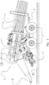
- FIGS 2-6 show a stuffing device 9 according to a first embodiment of the invention.
- the stuffing device 9 comprises the feed passage 11 formed between a lower plate 12 and an upper plate 13.
- An inlet 14 of the feed passage 11 is connected to the intake device 7, and an outlet 15 of the feed passage 11 is connected to the bale chamber 6.
- the stuffing mechanism 10 comprises at opposite sides of the piston press 1 tine arm elements connected with each other via a tine cross beam.
- the tine arm elements constitute a tine arm 16.
- the tine arm 16 is pivotably supported at pivot axis 17.
- the pivot axis 17 is mounted on a rotation element 17a which is rotatably mounted on the frame 2 at pivot axis 2a.
- a crank mechanism 18 is provided to drive the tine arm 16 in a pivotable movement with respect to the pivot axis 17, and a rotational drive (not shown) is provided to rotate the rotation element 17a and therewith the pivot axis 17 about the pivot axis 2a.
- An overload load clutch (not shown) is arranged in the drive mechanism.
- This combined movement results in a constant cyclic trajectory X of the tine arm 16 , that remains the same for stuffing trajectories B, see Figure 6 and the load trajectory A, see Figure 2 . Furthermore, the movement along this trajectory is continuous. The term continuous is used to indicate that during the cyclic movement the tine arm does not stop at a certain position, for instance to change the driving direction.
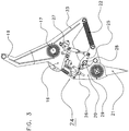
- FIG 3 shows the tine arm 16 in more detail.
- a first end 19 of the tine arm is connected to the crank mechanism 18 to move the tine arm 16 in the constant cyclic movement.
- a second end 20 of the tine arm 16 pivotably supports tines 21 (In Figure 3 only one tine 21 is shown; in practice multiple tines are provided in the direction perpendicular to the plane of the drawing to cover the width of the feed passage).
- the tines 21 are at least movable between an extended position, as shown in Figures 2 , 3 and 4 , and a retracted position, as shown in Figures 5 and 6 .
- the extended position In the extended position the tines 21 are pivoted in a position in which the tines extend radially with respect to the pivotal movement of the tine arm.
- the extended position is also the loading position.
- the tines 21 In the extended position the tines 21 will follow a load trajectory A when the tine arm 16 is moved along its constant cyclic trajectory X, as shown in Figure 2 .
- X shows the trajectory of the tine pivot 21a located on the tine arm 16.
- the tines 21 are freely movable between the extended position and the retracted position(s).
- a spring 22 is provided between a side arm 23 of the tine arm and the tines 21 to bias the tines 21 in the extended position.
- a tine locking device 24 is provided to lock the tines 21 in the extended position.
- the tine locking device 24 comprises a locking arm 25, pivotably mounted on the tine arm 16, a locking actuator 26, and a locking mechanism 27 between the locking actuator 26 and the locking arm 25.
- the locking arm 25 comprises a recess 28 arranged to receive a pin 29 mounted on the tines 21.
- the tines 21 can be moved from the loading position to one or more stuffing position wherein the tines 21 are pivoted to a retracted position with respect to the loading position. In this retracted position, the tines 21 will be at least partially moved out of the feed passage 11. During a stuffing trajectory the tines will at the beginning of the feed passage 11 be arranged in the extended position so that crop material will be pushed into the feed passage 11.
- a retaining element 30 is arranged in the feed passage 11 close to the outlet 15 thereof.
- the retaining element 30 is provided to hold crop material within the feed passage 11 during the stuffing cycles.
- the retaining element 30 is pivotably mounted and movable between an open position as shown in Figure 2 , and a retaining position as shown in Figure 4 . In the retaining position the retaining element 30 obstructs the outlet 15 of the feed passage 11 so that crop material in the feed passage will not be pressed out of the feed passage 11 during stuffing cycles.
- the retaining element 30 can be pivoted to the open position so that the tines 21 can push the crop material to the bale chamber 6.
- the movement of the retaining element 30 between the open position and the retaining position can be actively or passively controlled.
- a retaining element actuator may be provided to move the retaining element 30 between the retaining position and the open position.
- the movement of the retaining element 30 from the retaining position to the open position may be controlled, for instance, depending on a position of the tines 21 with respect to the tine arm 16.
- the force exerted by the tines 21, via the crop material, on the retaining element 30 may push the retaining element 30 to the open position, when this force exerts a threshold, for instance caused by a biasing element.
- the biasing element may bring the retaining element 30 back to the retaining position once the force decreases below the threshold.
- the tines 21 are shown at the beginning of feed passage 11, where the tines 21 are arranged in the extended position.
- the tine locking device 24 is positioned in the locked position, wherein the pin 29 is held in the recess 28.
- the tines 21 extend in the feed passage 11 so that crop material is moved towards the outlet 15.
- the tines 21 should be moved out of the feed passage 11 to avoid that the force on the crop material becomes too large and/or that crop material is too early loaded in the bale chamber 6.
- the pivotal movement of the tines is caused by crop material present in the feed passage 11.
- the tine locking device 24 should be arranged in the unlocked position as shown in Figure 5 by actuation of the locking actuator 26.
- the tines 21 In the return movement of the stuffing cycle, i.e. from a location near the outlet 15 towards the inlet 14, the crop material will no longer exert a force on the tines 21 and due to the spring force of the spring 22 the tines 21 will move back to the extended position. In this extended position, the tines may start one or more further stuffing cycles to stuff more crop material in the feed passage 11 until sufficient crop material has been gathered in the feed passage 11. It is remarked that at the beginning of these stuffing cycles the tines do not have to be locked by the tine locking device 24 in the extended position, since the spring 22 will hold the tines 21 in this extended position.
- the crop material can be loaded in the bale chamber 6 by performing a load cycle, i.e. the tines 21 will follow a load trajectory A as shown in Figure 2 .
- the tines 21 are locked by the tine locking device 24 in the extended or loading position for a complete cycle of the tine arm 16.
- the crop material present in the feed passage 11 will be pushed into the bale chamber 6 for the formation of a rectangular bale in this bale chamber 6.
- the moment of locking the pin 29 in the recess 28 for a complete cycle of the tine arm 16 may be dependent on the force or pressure exerted on the tines 21 or the retaining element 30. This force is relative for the quantity of crop material in the feed passage and the density thereof.
- the location in the stuffing cycle where the tines are moved from the extended position to a retracted position may be used for the decision to activate the tine locking device 24. As explained above, this location will gradually move towards the inlet 14 of the feed passage 11. The tines 21 may be locked to perform a load cycle when this location has reached a certain position with respect to the inlet 14 or another reference point.
- the signal for locking of the pin 29 in the recess 28 may also be used as an activation signal for an actuator configured to move the retaining element 30 from the retaining position to the open position.
- the tine locking device 24 When the load cycle is finished, the tine locking device 24 is positioned back in the unlocked position so that the tines 21 are free to pivot with respect to the tine arm 16, and the retaining element 30 is moved back to the retaining position. In the unlocked position of the tines 21 one or more stuffing cycles can be made, before another load cycle is performed.
- any other biasing element may be used.
- an active element may be arranged between the tine arm and the tines to move the tines actively between the loading position and one or more retracted positions.
- the locking mechanism may be obviated, when the active element in itself can function as a tine locking device.
- the tine locking device 24 is an example of a locking mechanism to lock the tines in the extended position. Any alternative embodiment of a locking device capable of locking the tines in the extended position may also be applied. In some embodiments, no separate locking mechanism is required since locking may be performed by other means, for instance an actuator.
- FIGS. 7-10 show an alternative embodiment of a stuffing device 9 according to the invention.
- the same parts or parts having the same function have been indicated by the same reference numerals.
- FIG 7 shows the stuffing device 9 in perspective view. From this view, it is clear that the tine arm 16 is constituted by two tine arm elements connected to each other by a cross beam on which the tines 21 are mounted.
- Figures 8-10 show the stuffing device 9 in side view.
- the stuffing device 9 comprises a tine arm 16 arranged to be driven by the crank mechanism 18 in a continuous and constant cyclic movement. Tines 21 are translatable supported on the tine arm 1. The tines 21 are translatable between an extended position, as shown in Figures 8 and 9 , and a retracted position, as shown in Figure 10 .
- a linear actuator 40 is connected to the tines 21 to move the tines 21 between the extended and retracted positions.
- the linear actuator 40 may for instance be a hydraulic cylinder.
- a linear guiding device 41 is provided on the tine arm 16 to guide the linear movement of the tines 21.
- a load trajectory A of the tines 21 is shown. During the complete load trajectory A the tines 21 are held in the extended position, and due to the constant cyclic movement of the tine arm 16, the tines 21 are moved along the load trajectory A.
- FIGS 8 and 9 show the stuffing device 9 during a stuffing cycle. In this stuffing cycle the tines 21 follow the stuffing trajectory B.
- the tines 21 are shown at the beginning of feed passage 11, and the tines 21 are arranged in the extended position.
- the retaining element 30 is positioned in the retaining position.
- the tines 21 are substantially moved out of the feed passage 11 to avoid that the force on the crop material becomes too large and/or that crop material is too early loaded in the bale chamber 6.
- the linear actuator 40 is activated to move the tines 21 to the retracted position.
- Figure 10 shows the tines 21 in the retracted position.
- the tines 21 are held in the retracted position during the movement of the tines 21 towards the outlet 15.
- the tines are brought back to the extended position.
- the tines 21 may start one or more further stuffing cycles to stuff crop material in the feed passage 11 until sufficient crop material has been gathered in the feed passage 11.
- the stuffing cycles may all follow the same trajectory, for instance stuffing trajectory B shown in Figures 9 and 10 , or the stuffing cycles may follow different stuffing trajectories, for instance dependent on the quantity of crop material already gathered in the feed passage 11.
- the crop material can be loaded in the bale chamber 6 by performing a load cycle, i.e. the tines 21 will follow a load trajectory A as shown in Figure 8 .
- the tines 21 are kept in the extended position for a complete cycle of the tine arm 16.
- the moment of carrying out a complete load cycle may be dependent on the force or pressure exerted on the tines 21 or the retaining element 30, or any other reason, for instance the number of subsequent stuffing cycles.
- the force or pressure is relative for the quantity of crop material in the feed passage and the density thereof.
- FIGS 11 and 12 show a third alternative embodiment of a stuffing device 9 according to the invention.
- the same parts or parts having the same function have been indicated by the same reference numerals.
- the tines 21 are rotationally mounted on the tine arm 16.
- the tines 21 comprise a first set of tine ends 21a extending in a first direction, and a second set of tine ends 21b extending in a second direction, whereby the angle between the first set of tine ends 21a and the second set of tine ends 21b is about 180 degrees.
- An actuator is provided to rotate the tines 21 when required.
- the tines 21 are rotated clockwise.
- the tines 21 can be positioned in an extended position, as shown in Figure 11 , and a retracted position, as shown in Figure 12 .
- the angle between the extended position and the retracted position is about 90 degrees.
- crank mechanism 18 The combination of movement of the crank mechanism 18 and rotation of rotation element 17a provides a continuous cyclic movement of the tine arm 16 similar to the embodiments of Figures 2-10 .
- the location where this movement from extended position to retracted position is made can be varied dependent on the desired stuffing trajectory.
- the tines 21 can again be rotated over an angle of substantially 90 degrees to return to an extended position.
- the other of the set of tine ends 21b, 21a now extends towards the feed passage 11.
- a number of stuffing trajectories can be made by rotation of the tine ends during the movement from inlet 14 to outlet 15 until the feed passage 11 is sufficiently filled. During these stuffing cycles the set of tine ends 21a, 21b will alternately be used to stuff crop material in the feed passage 11.
- a loading cycle can be started to load the stuffed crop material from the feed passage 11 into the bale chamber 6.
- the tines 21 are held in the extended position so that the crop material is pushed out of the feed passage 11.
- one or more stuffing cycles can follow for stuffing a new quantity of crop material in the feed passage 11.
- FIGS 13 - 15 show an alternative embodiment of a locking device 50 of the stuffing device 9 according to the invention.
- the same parts or parts having the same function have been indicated by the same reference numerals.
- the brake 50 may be a disc brake as shown.
- the brake disc 51 is fixed to a tine cross beam 52 and a calliper 53 is fixedly mounted on the tine arm 16.
- Other known configurations are possible such as for example a drum brake or magnetic brake.
- the brake 50 is activated / deactivated and closed / opened hydraulically, pneumatically or electrically.
- the piston bale press comprises not shown control means configured to open / close the brake 50 on the basis of one or more parameters.
- the brake 50 can also be configured as an overload device in connection with a not shown force or torque sensor.
- a torsion spring 54 is provided between the cross beam 52 and the tine arm 16.
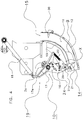
- Figure 14 shows the tines 21 during a stuffing trajectory B.
- the tines 21 are locked by the brake 50 in an extended position 55.
- the brake 50 is unlocked at point 57 of the trajectory B and the tines 21 are free to move from the extended position 55 to the retracted position 58 shown in dashed lines.
- the swivel movement of the tines 21 is caused by the precompressed material in the feed passage 11 increasing the tension of the spring 54.
- the brake 50 is deactivated during the return movement of the tines 21 along the stuffing trajectory B and reactivated at a point 59 when the tines 21 have been moved in the extended position 55 due to the force of the spring 54.
- a new stuffing cycle or a loading cycle starts- depending on the tine force or another parameter.
- Figure 15 shows a load trajectory A with tines 21 in extended position 55 locked by the brake 50 during the whole cycle.
- the brake 50 can also be applied in the third embodiment of the stuffing device of Figures 11 and 12 .
- Figure 16 and 17 show an alternative embodiment of a biasing element 60 of the stuffing device 9 according to the invention.
- the same parts or parts having the same function have been indicated by the same reference numerals.
- the spring to bias the tines 21 in the extended position is replaced by a cam track 60 and a cam roller 61 or follower on the tines 21.
- the cam track 60 is fixedly mounted to the frame 2 of the piston bale press and is arranged in the free room above the feed passage 11 and between the tine arms 16.
- the cam track 60 is formed as a rail curved according to the return movement of the tine pivot 21a along trajectory X, see Figure 2 , and extends from the inlet 14 to the outlet 15 and above the return trajectory of the tine crossbeam 52.
- cam track 60 which is arranged in the middle between the two tine arms 16.
- the cam roller 61 assigned to the cam track 60 is rotatably mounted on an arm 62 fixed to the cross beam 52 at the middle between the tine arms 16.
- the axis of the roller 61 is radially offset from the axis of the tine cross beam 52.
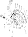
- Figure 16 shows the stuffing device 9 during movement of the tines 21 along a stuffing trajectory B.
- the arrangement of the cam roller 61 with respect to the cam track 60 is so selected that the cam track 60 comes into contact with the cam roller 61 in the outermost retracted position of the tines 21 shown in dashed lines.
- the tines 21 are brought back by the cam track 60 to the extended position in order to start a new stuffing or load cycle.
- FIG 17 the arrangement is shown during movement of the tines 21 along a load trajectory A, in which the tines 21 are locked in extended position.
- the cam roller 61 comes only in contact with the cam track 60 at the end of the return movement of the load trajectory A shortly before entering of the tines 21 into the feed passage 11 while the tines 21 in the in dashed line shown extended position are not actively controlled by the cam track 60 at the begin of the return movement of the tines 21 near the outlet 15, see distance between cam roller 61 and cam track 60.
- Two not shown cam tracks can be alternatively provided at opposite sides of the piston bale press interacting with a cam roller at both ends of the tine cross beam 52.
- the cam track can also be movable and / or spring loaded in order to influence the angle of the tines 21 under which they enter into the feed passage 11 at the end of the return movement of the stuffing cycle near the inlet 14.
- the cam track can also be sectionized in segments with different gradients. An individual cam roller may be assigned to each segment.
- Figure 18 shows in perspective view an alternative embodiment of a stuffing device 9 with a brake 50, see Figures 13-15 , in combination with a cam track 60, see Figures 16 and 17 , arranged in the middle of the piston bale press.
- a spring to move the tines 21 from the retracted to the extended position.
- the brake 50 is deactivated depending on the force or pressure exerted on the tines 21 or the retaining element 30 and the tines 21 are free to move into the retracted position.
- the tines 21 are moved by the cam track 60 from the retracted position, in which the brake 50 is deactivated to the extended position, in which the brake 50 is reactivated.
- the moment of carrying out a complete load cycle may again be dependent on the force or pressure exerted on the tines 21 or the retaining element 30 or, for instance the number of subsequent stuffing cycles.
- the retaining element (not shown) will be moved from the retaining position to the open position.
Landscapes
- Life Sciences & Earth Sciences (AREA)
- Environmental Sciences (AREA)
- Soil Working Implements (AREA)
- Apparatuses For Bulk Treatment Of Fruits And Vegetables And Apparatuses For Preparing Feeds (AREA)
- Absorbent Articles And Supports Therefor (AREA)
- Auxiliary Devices For And Details Of Packaging Control (AREA)
- Filling Or Emptying Of Bunkers, Hoppers, And Tanks (AREA)
- Basic Packing Technique (AREA)
- Harvesting Machines For Specific Crops (AREA)
Description
- The present invention relates to a piston bale press for forming rectangular bales of crop material.
- Such piston bale presses are for instance disclosed in
WO 02/074065 EP 0870 425 , andUS 6,647,706 . - A known embodiment of an agricultural piston bale press comprises a pressing piston arranged in a bale chamber to form bales of crop material, a main driving mechanism to drive the pressing piston; an intake device to take in crop material, and a stuffing device to stuff crop material taken in by the intake device and to load the stuffed crop material into the bale chamber. The stuffing device comprises a feed passage and a stuffing mechanism. The stuffing mechanism comprises a tine arm supporting tines and a drive mechanism. The drive mechanism is configured to move the tine arm along a stuffing trajectory to stuff crop material in the feed passage.
-
US 4,644,826 discloses a square baler with a packer assembly, cf.Fig. 1 andFig. 2 . A pair of forks is mounted on a pair oflinks 40, 42 which are joined together by a trunnion 44. The trunnion 44 is rotatably mounted in holes 45. Severalstub shaft members links 40, 42 for the forks 38 with crank arms 46, 48. The crank arms 46, 48 are fixed tocrank shafts 54, 56. Twosprockets 62, 64 are mounted on thecrank shaft 54 and are rotated by a chain 66. The tips of the forks 38 perform a kidney-shaped path 112.One end 86 of a rod 84 can slide through a hole in the trunnion 44. The other end 88 of the rod 84 is connected with a knob 112. Pushing or pulling at the knob 112 pulls or pushes at the trunnion 44 and makes the tips of the forks 38 rotating along an alternative path 112' or 112". - The square baler of
EP 1769674 A1 drives the stuffing tines (Rafferzinken 13) by means of a stuffing gear box (Raffergetriebe 30), cf.Fig. 1 . A telescopic connectingelement 29 being a cylinder 31 with a rod 32 is connected with a crank arm (Kurbelschwinge 34). The crank arm 34 is pivotally connected with a control shaft (Steuerwelle 35). The control shaft 35 is connected with a lever arm 36. The lever arm 36 drives a coupling rod (Koppelstange 37). The coupling rod 37 drives the stuffing lever (Rafferhebel 38). The stuffing lever 38 can rotate around an axle and carries on one end the stuffing tines (Rafferzinken 13). The tips of thestuffing tines 13 perform a stuffing stroke (Vorhub 14, cf.Fig. 3 ) for pre-pressing the crop material being in a feeding channel (Zuführkanal 15). The tips further perform a loading stroke (Füllhub 16, cf.Fig. 4 ) for loading the pre-pressed crop material into thepressing channel 2. A cylinder 44 connected with the crank arm 34 can be expanded (Fig. 3 ) or retracted (Fig. 4 ). When the cylinder is in the expanded position thetines 13 performsstuffing strokes 14, otherwise loadingstrokes 16. - A drawback of the known bale press is that the selective movement of the tine arm along a load trajectory and one or more stuffing trajectories requires a relative complex drive mechanism. Such bale presses, in accordance with the pre-characterising portion of
claim 1 are known fromEP1284594 . - It is an aim of the invention to provide an agricultural piston bale press having a tine arm drive mechanism having a relative simple design or at least to provide an alternative stuffing mechanism for an agricultural piston bale press.
- The present invention provides an agricultural piston bale press comprising a frame, a pressing piston arranged in a bale chamber to form bales of crop material, a main drive mechanism to drive the pressing piston, an intake device to take in crop material, and a stuffing device to stuff crop material taken in by the intake device and to load the stuffed crop material to the bale chamber, wherein the stuffing device comprises a feed passage and a stuffing mechanism, the stuffing mechanism comprising a tine arm supporting tines, which tines can be moved along at least one stuffing trajectory to stuff crop material in the feed passage, and a drive mechanism to drive the tine arm, wherein the tine arm comprises a first end and a second end, wherein the tine arm further comprises a first pivot axis mounted on a rotation element, the rotation element being mounted on the frame at a second pivot axis, wherein the drive mechanism comprises a crank mechanism connected to the first end of the tine arm and a rotational drive connected to the rotation element, the drive mechanism being configured to move the tine arm in a cyclic movement along a constant trajectory, characterised in that, the second end of the tine arm pivotally supporting the tines on the tine arm so that the tines can be arranged in different positions with respect to the second end of the tine arm to follow different trajectories, in that the stuffing mechanism is configured to move the tines between an extended position and a retracted position with respect to the second end of the tine arm during the stuffing trajectory, and in that the tines can be arranged in one or more positions with respect to the second end of the tine arm to follow a stuffing trajectory and in one or more positions to follow a load trajectory to load stuffed crop material from the feed passage into the bale chamber.
Preferably the cyclic movement of the tine arm along the constant trajectory is a continuous movement.
Preferably the tines can be positioned in a stationary loading position with respect to the tine arm to move the tines along the load trajectory.
More preferably the stuffing mechanism comprises a tine locking device, wherein the tine locking device has a locked position to lock the tines in the loading position and an unlocked position wherein the tines are freely movable with respect to the tine arm.
Alternatively, the stuffing mechanism comprises a biasing element to bias the tines in the loading position.
More preferably, the biasing element comprises a spring arranged between the tine arm and the tines and/ or at least one cam track arranged between the tines and the frame.
Preferably the tines are pivotally supported on the tine arm.
Preferably during a stuffing cycle, the tine locking device is arranged in the unlocked position, and wherein crop material in the feed passage pushes the tines out of the loading position to move the tines along the stuffing trajectory.
Preferably, the tines are translatable in a longitudinal direction of the tine arm between at least an extended position and a retracted position.
Preferably, the tines are rotationally mounted on the tine arm, wherein the tines comprise a first set of tine ends extending in a first direction with respect to a mounting location on the tine arm, and a second set of tine ends extending at a different angle with respect to the mounting location, wherein the tine ends are alternatively used for stuffing and/or loading of crop material.
Preferably the stuffing device is capable to move the tines along two or more stuffing trajectories.
Preferably the position of the tines with respect to the tine arm is controlled directly or indirectly on the basis of a force exerted on the tines, a position of the tines with respect to the tine arm, a location of the tines on the constant trajectory and/or a pressure exerted on the crop material in the feed passage. - Embodiments of a piston bale press according to the invention will now be described in further detail, by way of example only, with reference to the accompanying drawings, in which:
-
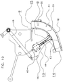
Figure 1 shows a piston bale press according to the invention; -
Figure 2 shows a side view of a stuffing device according to a first embodiment of the invention; -
Figure 3 shows the tine arm ofFigure 2 in more detail; -
Figures 4-6 show further side views of the embodiment ofFigure 2 ; -
Figure 7 shows a perspective view of a second embodiment of a stuffing device according to of the invention; -
Figures 8-10 show in side view the stuffing device ofFigure 7 ; -
Figures 11 and12 show in side view a third embodiment of a stuffing device according to the invention; -
Figure 13 shows a perspective view of the first embodiment of the stuffing device ofFigure 2 with an alternative locking device according to the invention; -
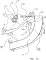
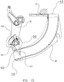
Figures 14 and15 show in side view the stuffing device ofFigure 13 ; -
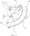
Figures 16 and17 show in side view the first embodiment of the stuffing device ofFigure 2 with an alternative biasing element; and -
Figure 18 shows in perspective view the stuffing device ofFigure 2 with the alternative locking device ofFigures 13-15 and the alternative biasing element ofFigures 16 and17 . -
Figure 1 shows a side view of a piston bale press, generally denoted with thereference numeral 1. Piston bale presses of this type are generally known and for instance disclosed inEP 1 769 674EP 0870 425 , andUS 4,106,268 . - The
piston bale press 1 comprises aframe 2 supported by wheels 3. Thepiston bale press 1 is configured to be connected at itsfront end 4 to a pulling vehicle, for instance a tractor. Thepiston bale press 1 further comprises apiston press 5 configured to press crop material in rectangular bales in abale chamber 6. Amain drive mechanism 5a is provided to move thepiston press 5 in an oscillating movement in thebale chamber 6 to compress crop material in thebale chamber 6. Thepiston bale press 1 further comprises anintake device 7 to take in crop material, i.e. agricultural harvested material, such as silage, grass, hay, or straw from aground surface 8. To improve the compression of the crop material, astuffing device 9 is provided to stuff crop material taken in by theintake device 7 in afeed passage 11 before it is loaded in thebale chamber 6. Thestuffing device 9 comprises astuffing mechanism 10 which is configured to stuff crop material in afeed passage 11 to obtain a quantity of crop material with a desired density before the crop material is loaded in thebale chamber 6. - The
stuffing mechanism 10 is configured to stuff crop material in the feed passage during a number of stuffing cycles. During each of these stuffing cycles a stuffing trajectory is followed in which crop material is compressed in the feed passage. When sufficient crop material is stuffed in thefeed passage 11, the stuffing mechanism will carry out a load cycle in which a load trajectory A is followed to push substantially all crop material present in the feed passage out of the feed passage into thebale chamber 6. - Different embodiments of a
stuffing device 9 according to the invention will now be discussed in more detail with reference toFigures 2-18 . -
Figures 2-6 show astuffing device 9 according to a first embodiment of the invention. Thestuffing device 9 comprises thefeed passage 11 formed between alower plate 12 and anupper plate 13. Aninlet 14 of thefeed passage 11 is connected to theintake device 7, and anoutlet 15 of thefeed passage 11 is connected to thebale chamber 6. - The
stuffing mechanism 10 comprises at opposite sides of thepiston press 1 tine arm elements connected with each other via a tine cross beam. The tine arm elements constitute atine arm 16. Thetine arm 16 is pivotably supported atpivot axis 17. Thepivot axis 17 is mounted on arotation element 17a which is rotatably mounted on theframe 2 atpivot axis 2a. - A
crank mechanism 18 is provided to drive thetine arm 16 in a pivotable movement with respect to thepivot axis 17, and a rotational drive (not shown) is provided to rotate therotation element 17a and therewith thepivot axis 17 about thepivot axis 2a. An overload load clutch (not shown) is arranged in the drive mechanism. - This combined movement results in a constant cyclic trajectory X of the
tine arm 16 , that remains the same for stuffing trajectories B, seeFigure 6 and the load trajectory A, seeFigure 2 . Furthermore, the movement along this trajectory is continuous. The term continuous is used to indicate that during the cyclic movement the tine arm does not stop at a certain position, for instance to change the driving direction. -
Figure 3 shows thetine arm 16 in more detail. Afirst end 19 of the tine arm is connected to thecrank mechanism 18 to move thetine arm 16 in the constant cyclic movement. Asecond end 20 of thetine arm 16 pivotably supports tines 21 (InFigure 3 only onetine 21 is shown; in practice multiple tines are provided in the direction perpendicular to the plane of the drawing to cover the width of the feed passage). - The
tines 21 are at least movable between an extended position, as shown inFigures 2 ,3 and4 , and a retracted position, as shown inFigures 5 and6 . In the extended position thetines 21 are pivoted in a position in which the tines extend radially with respect to the pivotal movement of the tine arm. In this embodiment, the extended position is also the loading position. In the extended position thetines 21 will follow a load trajectory A when thetine arm 16 is moved along its constant cyclic trajectory X, as shown inFigure 2 . X shows the trajectory of thetine pivot 21a located on thetine arm 16. - The
tines 21 are freely movable between the extended position and the retracted position(s). Aspring 22 is provided between aside arm 23 of the tine arm and thetines 21 to bias thetines 21 in the extended position. - A
tine locking device 24 is provided to lock thetines 21 in the extended position. Thetine locking device 24 comprises a lockingarm 25, pivotably mounted on thetine arm 16, a lockingactuator 26, and alocking mechanism 27 between the lockingactuator 26 and the lockingarm 25. The lockingarm 25 comprises arecess 28 arranged to receive apin 29 mounted on thetines 21. - In
Figure 3 the tines are shown in the locked position, wherein thepin 29 is located in therecess 28, thereby locking thetines 21 in a locking position. By actuation of theactuator 26, thelocking mechanism 27 will pivot lockingarm 25 in a pivotal movement so that thepin 29 is no longer located in therecess 28. In this unlocked position, the tines are free to move from the extended position to a retracted position. However, thespring 22 will still hold thetines 21 in the extended position as long as no other force is exerted on thetines 21. - To move the
tines 21 along a stuffing trajectory, thetines 21 can be moved from the loading position to one or more stuffing position wherein thetines 21 are pivoted to a retracted position with respect to the loading position. In this retracted position, thetines 21 will be at least partially moved out of thefeed passage 11. During a stuffing trajectory the tines will at the beginning of thefeed passage 11 be arranged in the extended position so that crop material will be pushed into thefeed passage 11. - A retaining
element 30 is arranged in thefeed passage 11 close to theoutlet 15 thereof. The retainingelement 30 is provided to hold crop material within thefeed passage 11 during the stuffing cycles. The retainingelement 30 is pivotably mounted and movable between an open position as shown inFigure 2 , and a retaining position as shown inFigure 4 . In the retaining position the retainingelement 30 obstructs theoutlet 15 of thefeed passage 11 so that crop material in the feed passage will not be pressed out of thefeed passage 11 during stuffing cycles. When the crop material should be loaded in thebale chamber 6, for instance when sufficient crop material is gathered in thefeed passage 11, the retainingelement 30 can be pivoted to the open position so that thetines 21 can push the crop material to thebale chamber 6. - The movement of the retaining
element 30 between the open position and the retaining position can be actively or passively controlled. In an active embodiment, a retaining element actuator may be provided to move the retainingelement 30 between the retaining position and the open position. The movement of the retainingelement 30 from the retaining position to the open position may be controlled, for instance, depending on a position of thetines 21 with respect to thetine arm 16. In a passive embodiment, the force exerted by thetines 21, via the crop material, on the retainingelement 30 may push the retainingelement 30 to the open position, when this force exerts a threshold, for instance caused by a biasing element. The biasing element may bring the retainingelement 30 back to the retaining position once the force decreases below the threshold. - Now, reference is made to
Figure 4-6 to describe the stuffing trajectory. In use, crop material will enter thefeed passage 11 viainlet 14. Thetines 21 will be moved along a stuffing trajectory B to stuff, i.e. pre-compress, crop material in thefeed passage 11. The retainingelement 30 is positioned in the retaining position to keep the crop material within thefeed passage 11. - In
Figure 4 , thetines 21 are shown at the beginning offeed passage 11, where thetines 21 are arranged in the extended position. Thetine locking device 24 is positioned in the locked position, wherein thepin 29 is held in therecess 28. Thetines 21 extend in thefeed passage 11 so that crop material is moved towards theoutlet 15. - At some location in the
feed passage 11 thetines 21 should be moved out of thefeed passage 11 to avoid that the force on the crop material becomes too large and/or that crop material is too early loaded in thebale chamber 6. In the shown embodiment the pivotal movement of the tines is caused by crop material present in thefeed passage 11. To make the pivotal movement of thetines 21 possible thetine locking device 24 should be arranged in the unlocked position as shown inFigure 5 by actuation of the lockingactuator 26. - As shown in
Figures 5 and6 , when thetines 21 are in the unlocked position and thetines 21 are moved further towards the outlet of thefeed passage 11, the tines will be pushed by crop material in retracted positions wherein thetines 21 are moved substantially out of thefeed passage 11. Due to the pivotal movement of the tines thespring 22 is extended, as clearly is shown inFigure 6 . - It will be clear that, in the embodiment of
Figures 2-6 , the location where thetines 21 will be moved out of the feed passage is dependent on the quantity of crop material in thefeed passage 11. Normally, in subsequent stuffing cycles this location will move towards theinlet 14 of the feed passage, since more and more crop material will be present in thefeed passage 11. - In the return movement of the stuffing cycle, i.e. from a location near the
outlet 15 towards theinlet 14, the crop material will no longer exert a force on thetines 21 and due to the spring force of thespring 22 thetines 21 will move back to the extended position. In this extended position, the tines may start one or more further stuffing cycles to stuff more crop material in thefeed passage 11 until sufficient crop material has been gathered in thefeed passage 11. It is remarked that at the beginning of these stuffing cycles the tines do not have to be locked by thetine locking device 24 in the extended position, since thespring 22 will hold thetines 21 in this extended position. - Once sufficient crop material is present in the
feed passage 11, the crop material can be loaded in thebale chamber 6 by performing a load cycle, i.e. thetines 21 will follow a load trajectory A as shown inFigure 2 . To carry out a load cycle, thetines 21 are locked by thetine locking device 24 in the extended or loading position for a complete cycle of thetine arm 16. As a consequence, the crop material present in thefeed passage 11 will be pushed into thebale chamber 6 for the formation of a rectangular bale in thisbale chamber 6. - The moment of locking the
pin 29 in therecess 28 for a complete cycle of thetine arm 16 may be dependent on the force or pressure exerted on thetines 21 or the retainingelement 30. This force is relative for the quantity of crop material in the feed passage and the density thereof. - As an alternative, the location in the stuffing cycle where the tines are moved from the extended position to a retracted position may be used for the decision to activate the
tine locking device 24. As explained above, this location will gradually move towards theinlet 14 of thefeed passage 11. Thetines 21 may be locked to perform a load cycle when this location has reached a certain position with respect to theinlet 14 or another reference point. - The signal for locking of the
pin 29 in therecess 28 may also be used as an activation signal for an actuator configured to move the retainingelement 30 from the retaining position to the open position. - When the load cycle is finished, the
tine locking device 24 is positioned back in the unlocked position so that thetines 21 are free to pivot with respect to thetine arm 16, and the retainingelement 30 is moved back to the retaining position. In the unlocked position of thetines 21 one or more stuffing cycles can be made, before another load cycle is performed. - The above-described embodiment should be regarded as an example of a stuffing mechanism comprising
movable tines 21 supported on atine arm 16 configured to make a constant cyclic movement. Many parts could be carried out in an alternative way or may even not be required to carry out the invention. - For instance, as an alternative for the
spring 22, any other biasing element may be used. In an alternative embodiment, an active element may be arranged between the tine arm and the tines to move the tines actively between the loading position and one or more retracted positions. In such embodiment, the locking mechanism may be obviated, when the active element in itself can function as a tine locking device. - The
tine locking device 24 is an example of a locking mechanism to lock the tines in the extended position. Any alternative embodiment of a locking device capable of locking the tines in the extended position may also be applied. In some embodiments, no separate locking mechanism is required since locking may be performed by other means, for instance an actuator. -
Figures 7-10 show an alternative embodiment of astuffing device 9 according to the invention. The same parts or parts having the same function have been indicated by the same reference numerals. -
Figure 7 shows thestuffing device 9 in perspective view. From this view, it is clear that thetine arm 16 is constituted by two tine arm elements connected to each other by a cross beam on which thetines 21 are mounted.Figures 8-10 show thestuffing device 9 in side view. - The
stuffing device 9 comprises atine arm 16 arranged to be driven by thecrank mechanism 18 in a continuous and constant cyclic movement.Tines 21 are translatable supported on thetine arm 1. Thetines 21 are translatable between an extended position, as shown inFigures 8 and9 , and a retracted position, as shown inFigure 10 . - A
linear actuator 40 is connected to thetines 21 to move thetines 21 between the extended and retracted positions. Thelinear actuator 40 may for instance be a hydraulic cylinder. Alinear guiding device 41 is provided on thetine arm 16 to guide the linear movement of thetines 21. - The advantage of the embodiment of
Figures 7-10 is that the movement of thetines 16 with respect to thetine arm 16 is linear. A relative simple and reliable actuator can be used to perform this action. - In
Figure 7 , a load trajectory A of thetines 21 is shown. During the complete load trajectory A thetines 21 are held in the extended position, and due to the constant cyclic movement of thetine arm 16, thetines 21 are moved along the load trajectory A. -
Figures 8 and9 show thestuffing device 9 during a stuffing cycle. In this stuffing cycle thetines 21 follow the stuffing trajectory B. - In
Figure 8 , thetines 21 are shown at the beginning offeed passage 11, and thetines 21 are arranged in the extended position. The retainingelement 30 is positioned in the retaining position. At some location in thefeed passage 11 thetines 21 are substantially moved out of thefeed passage 11 to avoid that the force on the crop material becomes too large and/or that crop material is too early loaded in thebale chamber 6. At this location, thelinear actuator 40 is activated to move thetines 21 to the retracted position. -
Figure 10 shows thetines 21 in the retracted position. Thetines 21 are held in the retracted position during the movement of thetines 21 towards theoutlet 15. During the return movement of the tines towards theinlet 14 of thefeed passage 11 to begin a new stuffing cycle or a load cycle, the tines are brought back to the extended position. - In this extended position, the
tines 21 may start one or more further stuffing cycles to stuff crop material in thefeed passage 11 until sufficient crop material has been gathered in thefeed passage 11. The stuffing cycles may all follow the same trajectory, for instance stuffing trajectory B shown inFigures 9 and10 , or the stuffing cycles may follow different stuffing trajectories, for instance dependent on the quantity of crop material already gathered in thefeed passage 11. - Once sufficient crop material is present in the
feed passage 11, the crop material can be loaded in thebale chamber 6 by performing a load cycle, i.e. thetines 21 will follow a load trajectory A as shown inFigure 8 . To carry out a load cycle, thetines 21 are kept in the extended position for a complete cycle of thetine arm 16. - The moment of carrying out a complete load cycle may be dependent on the force or pressure exerted on the
tines 21 or the retainingelement 30, or any other reason, for instance the number of subsequent stuffing cycles. The force or pressure is relative for the quantity of crop material in the feed passage and the density thereof. When the load cycle is finished, one or more stuffing cycles can be made, before another load cycle is performed. -
Figures 11 and12 show a third alternative embodiment of astuffing device 9 according to the invention. The same parts or parts having the same function have been indicated by the same reference numerals. - In this embodiment, the
tines 21 are rotationally mounted on thetine arm 16. Thetines 21 comprise a first set of tine ends 21a extending in a first direction, and a second set of tine ends 21b extending in a second direction, whereby the angle between the first set of tine ends 21a and the second set of tine ends 21b is about 180 degrees. - An actuator is provided to rotate the
tines 21 when required. Thetines 21 are rotated clockwise. Thetines 21 can be positioned in an extended position, as shown inFigure 11 , and a retracted position, as shown inFigure 12 . The angle between the extended position and the retracted position is about 90 degrees. - The combination of movement of the
crank mechanism 18 and rotation ofrotation element 17a provides a continuous cyclic movement of thetine arm 16 similar to the embodiments ofFigures 2-10 . - When a complete cycle of the
tine arm 16 is made in the extended position, one of the sets of tine ends 21a, 21b will be moved through thefeed passage 11 and follow a load trajectory. By positioning thetines 21 in the retracted position, the tine ends of both sets of tine ends 21a, 21b can be kept substantially out of thefeed passage 11. Thus, during the movement of the tines from theinlet 14 to theoutlet 15 of thefeed passage 11, a movement of thetines 21 from the extended position to a retracted position by rotation of the tines over an angle of substantially 90 degrees results in a stuffing trajectory. - The location where this movement from extended position to retracted position is made, can be varied dependent on the desired stuffing trajectory. During the return movement from the
outlet 15 to theinlet 14, thetines 21 can again be rotated over an angle of substantially 90 degrees to return to an extended position. However, as a result of the clockwise rotation, the other of the set of tine ends 21b, 21a now extends towards thefeed passage 11. A number of stuffing trajectories can be made by rotation of the tine ends during the movement frominlet 14 tooutlet 15 until thefeed passage 11 is sufficiently filled. During these stuffing cycles the set of tine ends 21a, 21b will alternately be used to stuff crop material in thefeed passage 11. - Once the
feed passage 11 is sufficiently filled a loading cycle can be started to load the stuffed crop material from thefeed passage 11 into thebale chamber 6. During the whole load cycle, thetines 21 are held in the extended position so that the crop material is pushed out of thefeed passage 11. Thereafter, one or more stuffing cycles can follow for stuffing a new quantity of crop material in thefeed passage 11. -
Figures 13 - 15 show an alternative embodiment of alocking device 50 of thestuffing device 9 according to the invention. The same parts or parts having the same function have been indicated by the same reference numerals. - From these views it is clear that the
tine locking device 24 ofFigure 2 is replaced by abrake 50 which is arranged between thetine arm 16 and thetines 21 and moves together with thetine arm 16. - The
brake 50 may be a disc brake as shown. Thebrake disc 51 is fixed to atine cross beam 52 and acalliper 53 is fixedly mounted on thetine arm 16. Other known configurations are possible such as for example a drum brake or magnetic brake. - The
brake 50 is activated / deactivated and closed / opened hydraulically, pneumatically or electrically. - The piston bale press comprises not shown control means configured to open / close the
brake 50 on the basis of one or more parameters. Thebrake 50 can also be configured as an overload device in connection with a not shown force or torque sensor.
Atorsion spring 54 is provided between thecross beam 52 and thetine arm 16. -
Figure 14 shows thetines 21 during a stuffing trajectory B. At the beginning of thefeed passage 11 thetines 21 are locked by thebrake 50 in anextended position 55. During further movement of thetines 21 in direction of the arrow 56 thebrake 50 is unlocked at point 57 of the trajectory B and thetines 21 are free to move from theextended position 55 to the retracted position 58 shown in dashed lines. - The swivel movement of the
tines 21 is caused by the precompressed material in thefeed passage 11 increasing the tension of thespring 54. Thebrake 50 is deactivated during the return movement of thetines 21 along the stuffing trajectory B and reactivated at a point 59 when thetines 21 have been moved in theextended position 55 due to the force of thespring 54. A new stuffing cycle or a loading cycle starts- depending on the tine force or another parameter. -
Figure 15 shows a load trajectory A withtines 21 inextended position 55 locked by thebrake 50 during the whole cycle. Thebrake 50 can also be applied in the third embodiment of the stuffing device ofFigures 11 and12 . -
Figure 16 and17 show an alternative embodiment of a biasingelement 60 of thestuffing device 9 according to the invention. The same parts or parts having the same function have been indicated by the same reference numerals. - In this embodiment the spring to bias the
tines 21 in the extended position is replaced by acam track 60 and acam roller 61 or follower on thetines 21. Thecam track 60 is fixedly mounted to theframe 2 of the piston bale press and is arranged in the free room above thefeed passage 11 and between thetine arms 16. Thecam track 60 is formed as a rail curved according to the return movement of thetine pivot 21a along trajectory X, seeFigure 2 , and extends from theinlet 14 to theoutlet 15 and above the return trajectory of thetine crossbeam 52. - In
Figures 16 and17 there is only provided onecam track 60 which is arranged in the middle between the two tine arms 16.Thecam roller 61 assigned to thecam track 60 is rotatably mounted on anarm 62 fixed to thecross beam 52 at the middle between thetine arms 16. The axis of theroller 61 is radially offset from the axis of thetine cross beam 52. - The mechanical arrangement of the
cam track 60 and thecam roller 61 is clear in detail fromFigure 16 and17 . -
Figure 16 shows thestuffing device 9 during movement of thetines 21 along a stuffing trajectory B. The arrangement of thecam roller 61 with respect to thecam track 60 is so selected that thecam track 60 comes into contact with thecam roller 61 in the outermost retracted position of thetines 21 shown in dashed lines. During the return movement of thetines 21 in direction of thearrow 63 towards theinlet 14 thetines 21 are brought back by thecam track 60 to the extended position in order to start a new stuffing or load cycle. - In
Figure 17 the arrangement is shown during movement of thetines 21 along a load trajectory A, in which thetines 21 are locked in extended position. Thecam roller 61 comes only in contact with thecam track 60 at the end of the return movement of the load trajectory A shortly before entering of thetines 21 into thefeed passage 11 while thetines 21 in the in dashed line shown extended position are not actively controlled by thecam track 60 at the begin of the return movement of thetines 21 near theoutlet 15, see distance betweencam roller 61 andcam track 60. - Two not shown cam tracks can be alternatively provided at opposite sides of the piston bale press interacting with a cam roller at both ends of the
tine cross beam 52. - The cam track can also be movable and / or spring loaded in order to influence the angle of the
tines 21 under which they enter into thefeed passage 11 at the end of the return movement of the stuffing cycle near theinlet 14. The cam track can also be sectionized in segments with different gradients. An individual cam roller may be assigned to each segment. -
Figure 18 shows in perspective view an alternative embodiment of astuffing device 9 with abrake 50, seeFigures 13-15 , in combination with acam track 60, seeFigures 16 and17 , arranged in the middle of the piston bale press. As difference and advantage of this combination there is no need for a spring to move thetines 21 from the retracted to the extended position. - On the load trajectory A, see
Figure 17 , thebrake 50 is activated and locks thetines 21 during the full cycle. - During the forward movement of the
tines 21 along the stuffing trajectory B, seeFigure 16 , thebrake 50 is deactivated depending on the force or pressure exerted on thetines 21 or the retainingelement 30 and thetines 21 are free to move into the retracted position. On the return movement thetines 21 are moved by thecam track 60 from the retracted position, in which thebrake 50 is deactivated to the extended position, in which thebrake 50 is reactivated. - The moment of carrying out a complete load cycle may again be dependent on the force or pressure exerted on the
tines 21 or the retainingelement 30 or, for instance the number of subsequent stuffing cycles. At the same moment, the retaining element (not shown) will be moved from the retaining position to the open position.
Claims (12)
- An agricultural piston bale press (1), comprising:- a frame (2);- a pressing piston (5) arranged in a bale chamber (6) to form bales of crop material;- a main drive mechanism (5a) to drive the pressing piston;- an intake device (7) to take in crop material, and- a stuffing device (9) to stuff crop material taken in by the intake device and to load the stuffed crop material to the bale chamber,wherein the stuffing device comprises a feed passage (11) and a stuffing mechanism (10), the stuffing mechanism comprising a tine arm (16) supporting tines (21), which tines can be moved along at least one stuffing trajectory (B) to stuff crop material in the feed passage, and a drive mechanism to drive the tine arm,
wherein the tine arm (16) comprises a first end (19) and a second end (20)
wherein the tine arm (16) further comprises a first pivot axis (17) mounted on a rotation element (17a), the rotation element (17a) being mounted on the frame (2) at a second pivot axis (2a);
wherein the drive mechanism comprises a crank mechanism connected to the first end of the tine arm (16) and a rotational drive connected to the rotation element (17), the drive mechanism being configured to move the tine arm (16) in a cyclic movement along a constant trajectory (X),
characterised in that, the second end (20) of the tine arm (16) pivotally supporting the tines (21) on the tine arm (16) so that the tines can be arranged in different positions with respect to the second end of the tine arm (16) to follow different trajectories,
in that the stuffing mechanism is configured to move the tines (21) between an extended position and a retracted position with respect to the second end (20) of the tine arm (16) during the stuffing trajectory (B), and
in that the tines (21) can be arranged in one or more positions with respect to the second end (20) of the tine arm (16) to follow a stuffing trajectory (B) and in one or more positions to follow a load trajectory (A) to load stuffed crop material from the feed passage (11) into the bale chamber (6). - The agricultural piston bale press (1) of claim 1, wherein the cyclic movement of the tine arm (16) along the constant trajectory (X) is a continuous movement.
- The agricultural piston bale press (1) of any of the preceding claims, wherein the tines (21) can be positioned in a stationary loading position with respect to the tine arm (16) to move the tines along the load trajectory (A).
- The agricultural piston bale press (1) of claim 3, wherein the stuffing mechanism (10) comprises a tine locking device (24, 50), wherein the tine locking device (24, 50) has a locked position to lock the tines (21) in the loading position and an unlocked position wherein the tines are freely movable with respect to the tine arm (16).
- The agricultural piston bale press (1) of claim 3, wherein the stuffing mechanism (10) comprises a biasing element (22) to bias the tines (21) in the loading position.
- The agricultural piston bale press (1) of claim 5, wherein the biasing element (22) comprises a spring arranged between the tine arm (16) and the tines (21) and/ or at least one cam track (60) arranged between the tines (21) and the frame (2).
- The agricultural piston bale press (1) of any of the preceding claims, wherein the tines (21) are pivotably supported on the tine arm (16).
- The agricultural piston press (1) of claim 4 or claim 6, wherein, during a stuffing cycle, the tine locking device (24) is arranged in the unlocked position, and wherein crop material in the feed passage (11) pushes the tines (21) out of the loading position to move the tines along the stuffing trajectory.
- The agricultural piston bale press (1) of any of the claims 1 to 5, wherein the tines (21) are translatable in a longitudinal direction of the tine arm (16) between at least an extended position and a retracted position.
- The agricultural piston bale press (1) of any of the preceding claims, wherein the tines (21) are rotationally mounted on the tine arm (16), wherein the tines comprise a first set of tine ends extending in a first direction with respect to a mounting location on the tine arm, and a second set of tine ends extending at a different angle with respect to the mounting location, wherein the tine ends are alternatively used for stuffing and/or loading of crop material.
- The agricultural piston bale press (1) of any of the preceding claims, wherein the stuffing device (9) is capable to move the tines along two or more stuffing trajectories.
- The agricultural piston bale press (1) of any of the preceding claims, wherein the position of the tines with respect to the tine arm is controlled directly or indirectly on the basis of a force exerted on the tines, a position of the tines with respect to the tine arm, a location of the tines on the constant trajectory and/or a pressure exerted on the crop material in the feed passage.
Applications Claiming Priority (3)
| Application Number | Priority Date | Filing Date | Title |
|---|---|---|---|
| US35715910P | 2010-06-22 | 2010-06-22 | |
| EP11726203.0A EP2584882B2 (en) | 2010-06-22 | 2011-06-15 | Tine control for balers |
| PCT/NL2011/000048 WO2011162597A1 (en) | 2010-06-22 | 2011-06-15 | Tine control for balers |
Related Parent Applications (2)
| Application Number | Title | Priority Date | Filing Date |
|---|---|---|---|
| EP11726203.0A Division EP2584882B2 (en) | 2010-06-22 | 2011-06-15 | Tine control for balers |
| EP11726203.0A Division-Into EP2584882B2 (en) | 2010-06-22 | 2011-06-15 | Tine control for balers |
Publications (2)
| Publication Number | Publication Date |
|---|---|
| EP3020267A1 EP3020267A1 (en) | 2016-05-18 |
| EP3020267B1 true EP3020267B1 (en) | 2019-08-07 |
Family
ID=43242878
Family Applications (2)
| Application Number | Title | Priority Date | Filing Date |
|---|---|---|---|
| EP15193270.4A Active EP3020267B1 (en) | 2010-06-22 | 2011-06-15 | Tine control for balers |
| EP11726203.0A Not-in-force EP2584882B2 (en) | 2010-06-22 | 2011-06-15 | Tine control for balers |
Family Applications After (1)
| Application Number | Title | Priority Date | Filing Date |
|---|---|---|---|
| EP11726203.0A Not-in-force EP2584882B2 (en) | 2010-06-22 | 2011-06-15 | Tine control for balers |
Country Status (8)
| Country | Link |
|---|---|
| US (1) | US8683779B2 (en) |
| EP (2) | EP3020267B1 (en) |
| CN (2) | CN105850402B (en) |
| BR (1) | BR112012032895B1 (en) |
| NL (1) | NL1038109C2 (en) |
| PL (1) | PL2584882T3 (en) |
| RU (1) | RU2567014C2 (en) |
| WO (1) | WO2011162597A1 (en) |
Families Citing this family (19)
| Publication number | Priority date | Publication date | Assignee | Title |
|---|---|---|---|---|
| BE1018837A3 (en) * | 2009-07-28 | 2011-09-06 | Cnh Belgium Nv | A METHOD FOR RELEASING BLOCK QUOTE IN THE INPUT CHANNEL OF A RECTANGULAR BALL PRESS. |
| NL1038109C2 (en) * | 2010-06-22 | 2012-01-23 | Forage Innovations Bv | Tine control for balers. |
| BE1021162B1 (en) | 2013-08-27 | 2016-01-12 | Cnh Industrial Belgium Nv | SYSTEM FOR ACTIVATING THE FILLER OF A BALEN PRESS FOR USE IN AGRICULTURE |
| BE1022128B1 (en) * | 2014-06-30 | 2016-02-17 | Cnh Industrial Belgium Nv | FUEL UNIT FOR A BALEN PRESS FOR USE IN AGRICULTURE WITH AN AUTOMATIC DENSITY SCHEME |
| BE1021933B1 (en) * | 2014-07-09 | 2016-01-27 | Cnh Industrial Belgium Nv | HYDRAULIC BRAKE WITH ENERGY RECOVERY FOR A FUEL UNIT IN A BALL PRESS FOR USE IN AGRICULTURE |
| BE1023264B1 (en) * | 2015-10-20 | 2017-01-17 | Cnh Industrial Belgium Nv | AGRICULTURAL BALL PRESS, AGRICULTURAL BALL PRESS SYSTEM, METHOD FOR CONFIGURING AN AGRICULTURAL BALL PRESS AND METHOD FOR FORMING BALES |
| BE1023242B1 (en) * | 2015-10-20 | 2017-01-06 | Cnh Industrial Belgium Nv | AGRICULTURAL BALL PRESS |
| US10881050B2 (en) | 2015-12-30 | 2021-01-05 | Agco Corporation | Baler stuffer selectively operable to provide partial stuffing strokes |
| BE1023943B1 (en) * | 2016-04-11 | 2017-09-15 | Cnh Industrial Belgium Nv | RECTANGULAR BALL PRESS WITH IMPROVED FULL PROGRAM MECHANISM |
| US10588270B2 (en) * | 2017-08-31 | 2020-03-17 | Deere & Company | Baler feed system |
| CN108496582B (en) * | 2018-03-26 | 2019-09-13 | 湖南农业大学 | A kind of Rape Straw binding apparatus |
| EA034413B1 (en) * | 2018-05-16 | 2020-02-05 | Павел Валерьевич Шаплыко | Method and device for feeding harvested crop material for baling |
| CN108770471B (en) * | 2018-07-23 | 2019-09-13 | 湖南农业大学 | A binding clutch for a baler |
| DE102020002580B4 (en) * | 2020-04-29 | 2024-01-25 | Maschinenfabrik Bernard Krone GmbH & Co. KG | Conveying and collecting device with a drivable conveying and collecting unit and agricultural crop press with the conveying and collecting device |
| EP3912456B1 (en) * | 2020-05-19 | 2024-12-25 | CNH Industrial Belgium N.V. | Agricultural vehicle with retainer for blockage removing windguard |
| DE102021106061A1 (en) * | 2021-03-12 | 2022-09-15 | Maschinenfabrik Bernard Krone GmbH & Co. KG | CONVEYOR DEVICE FOR A BALER |
| EP4111848B1 (en) | 2021-06-30 | 2025-05-21 | CNH Industrial Belgium N.V. | Stuffer assembly for an agricultural baler |
| GB2621612A (en) * | 2022-08-17 | 2024-02-21 | Kuhn Geldrop Bv | Square baler |
| US20240224877A1 (en) * | 2023-01-05 | 2024-07-11 | Deere & Company | Large square baler with controllable feeder system |
Family Cites Families (39)
| Publication number | Priority date | Publication date | Assignee | Title |
|---|---|---|---|---|
| US2409478A (en) * | 1943-11-17 | 1946-10-15 | Int Harvester Co | Feeder for balers |
| FR1185953A (en) * | 1957-11-09 | 1959-08-11 | Rech Expl Invent Guillotin | Further training for straw baler feeders |
| FR2231306B1 (en) * | 1973-05-28 | 1978-03-31 | Welger Geb | |
| US4132163A (en) * | 1976-04-09 | 1979-01-02 | Hesston Corporation | Baler loading method |
| US4106268A (en) | 1976-11-01 | 1978-08-15 | Hesston Corporation | Method for loading and baling crop material |
| US4514968A (en) * | 1982-11-04 | 1985-05-07 | Sperry Corporation | In-line rectangular baler |
| FR2542969B1 (en) * | 1983-03-22 | 1986-03-14 | Rivierre Casalis | PISTON PRESS FOR FORMING FORAGE BALLS |
| US4524574A (en) * | 1984-05-18 | 1985-06-25 | Hesston Corporation | Underfed crop baler having single rotary feeder |
| US4644826A (en) | 1984-08-24 | 1987-02-24 | Toyota Jidosha Kabushiki Kaisha | Idling control system for an automatic transmission providing smooth starting off action |
| US4656938A (en) * | 1986-02-07 | 1987-04-14 | New Holland Inc. | Baler stuffer mechanism |
| US4644862A (en) * | 1986-03-03 | 1987-02-24 | New Holland Inc. | Adjusting apparatus for baler packer assembly |
| DE3638792A1 (en) * | 1986-11-13 | 1988-05-26 | Claas Ohg | PISTON PRESS FOR THE PRODUCTION OF PRESS BALES FROM HARVESTED PRODUCTS |
| FR2617673B1 (en) * | 1987-07-09 | 1989-12-15 | Hesston Sa | PARALLELEPIPED BALL BALER |
| DD272983A1 (en) † | 1988-06-13 | 1989-11-01 | Fortschritt Veb K | FEEDING ESTABLISHMENT OF A BALING PRESS FOR AGRICULTURAL HARVEST |
| DD287866A5 (en) † | 1989-09-26 | 1991-03-14 | Kombinat Fortschritt Landmaschinen Veb Erntemaschinen Neustadt,De | FOUNDER DEVICE FOR COMPRESSION PRESSING |
| EP0636308B1 (en) * | 1993-07-23 | 1999-03-03 | New Holland Belgium N.V. | Baler stuffer mechanism |
| DE19628604A1 (en) * | 1996-07-16 | 1998-01-22 | Claas Usines France | Drive system for agricultural big balers |
| US5842335A (en) * | 1996-10-04 | 1998-12-01 | Hay & Forage Industries | Bottom loading, in-line square baler with dual purpose stuffer |
| US5819515A (en) * | 1996-10-18 | 1998-10-13 | Hay & Forage Industries | Eased inlet tailgate roll arrangement for variable chamber round baler |
| US6029434A (en) * | 1996-10-18 | 2000-02-29 | Hay & Forage Industries | Down turning stub augers on wide pick-up for round balers |
| DE19709604A1 (en) * | 1997-03-08 | 1998-09-10 | Claas Usines France | Method and device for fine adjustment of motion sequences on big balers |
| DE19715280C2 (en) * | 1997-04-12 | 2000-10-19 | Claas Ohg | Piston press for the production of pressed bales from crops |
| US5950410A (en) * | 1998-03-03 | 1999-09-14 | Deere & Company | Hydraulically powered baler plunger drive mechanism |
| DE19829276C2 (en) * | 1998-07-01 | 2001-01-04 | Krone Bernhard Gmbh Maschf | Pick-up press for agricultural crops |
| US6298646B1 (en) * | 2000-03-01 | 2001-10-09 | Hay & Forage Industries | Square baler with infeed cutter |
| DE10023443A1 (en) * | 2000-05-12 | 2001-11-15 | Deere & Co | Conveyor |
| US6543342B2 (en) * | 2000-06-29 | 2003-04-08 | New Holland North America, Inc. | Method for determining a value relating to compressing rate of a baler |
| DE20104700U1 (en) | 2001-03-19 | 2001-06-13 | Kverneland Geldrop B.V., Geldrop | Piston press |
| US6647706B2 (en) | 2001-10-25 | 2003-11-18 | Deere & Company | Two-cylinder mechanism for operating baling chamber stuffer |
| US6679042B1 (en) * | 2002-11-12 | 2004-01-20 | Acco Corporation | Infeed cutter baler having increased throughput |
| DE102004019286A1 (en) * | 2004-04-21 | 2005-12-01 | Deere & Company, Moline | baler |
| DE10343386A1 (en) * | 2003-09-19 | 2005-05-12 | Deere & Co | Baler and procedure |
| DE102005046552A1 (en) * | 2005-09-28 | 2007-04-12 | Usines Claas France S.A.S., St. Rémy-Woippy | Agricultural piston press |
| CN200969765Y (en) * | 2006-04-03 | 2007-11-07 | 中国农业机械化科学研究院呼和浩特分院 | Grass picking and round baling machine |
| CN201051800Y (en) * | 2006-10-19 | 2008-04-30 | 上海电气集团现代农业装备成套有限公司 | Chain row transporting device for fixed form round straw bundle packing machine feeding |
| CN201216080Y (en) * | 2008-06-05 | 2009-04-08 | 黑龙江省农业机械工程科学研究院 | Silage round baler |
| CN201422258Y (en) * | 2009-06-26 | 2010-03-17 | 中国农业机械化科学研究院 | A straw picking square baler |
| EP2496069B1 (en) | 2009-11-02 | 2013-08-28 | Lely Patent N.V. | Stuffing device |
| NL1038109C2 (en) * | 2010-06-22 | 2012-01-23 | Forage Innovations Bv | Tine control for balers. |
-
2010
- 2010-07-19 NL NL1038109A patent/NL1038109C2/en not_active IP Right Cessation
-
2011
- 2011-06-15 CN CN201610238044.7A patent/CN105850402B/en active Active
- 2011-06-15 BR BR112012032895-6A patent/BR112012032895B1/en not_active IP Right Cessation
- 2011-06-15 WO PCT/NL2011/000048 patent/WO2011162597A1/en not_active Ceased
- 2011-06-15 EP EP15193270.4A patent/EP3020267B1/en active Active
- 2011-06-15 RU RU2013102584/13A patent/RU2567014C2/en active
- 2011-06-15 PL PL11726203T patent/PL2584882T3/en unknown
- 2011-06-15 EP EP11726203.0A patent/EP2584882B2/en not_active Not-in-force
- 2011-06-15 CN CN201180030560.6A patent/CN102946712B/en active Active
-
2012
- 2012-12-20 US US13/721,067 patent/US8683779B2/en active Active
Non-Patent Citations (1)
| Title |
|---|
| None * |
Also Published As
| Publication number | Publication date |
|---|---|
| EP3020267A1 (en) | 2016-05-18 |
| PL2584882T3 (en) | 2016-05-31 |
| NL1038109C2 (en) | 2012-01-23 |
| CN105850402B (en) | 2018-04-06 |
| BR112012032895B1 (en) | 2019-04-30 |
| WO2011162597A1 (en) | 2011-12-29 |
| EP2584882A1 (en) | 2013-05-01 |
| US20130104512A1 (en) | 2013-05-02 |
| EP2584882B1 (en) | 2015-11-11 |
| RU2013102584A (en) | 2014-07-27 |
| CN105850402A (en) | 2016-08-17 |
| US8683779B2 (en) | 2014-04-01 |
| CN102946712A (en) | 2013-02-27 |
| BR112012032895A2 (en) | 2016-10-04 |
| RU2567014C2 (en) | 2015-10-27 |
| CN102946712B (en) | 2016-04-13 |
| EP2584882B2 (en) | 2019-05-01 |
Similar Documents
| Publication | Publication Date | Title |
|---|---|---|
| EP2584882B1 (en) | Tine control for balers | |
| CA2420655C (en) | Large rectangular baler having hydraulically powered functions, and control system therefor | |
| US8561532B2 (en) | Stuffing device | |
| EP0636308B1 (en) | Baler stuffer mechanism | |
| EP2099283A2 (en) | Baler with multi-auger pickup | |
| EP3308631B1 (en) | Agricultural harvesting machine | |
| EP2962544B1 (en) | Stuffer unit for an agricultural baler with automatic density control | |
| CA2391748C (en) | Two-cylinder mechanism for operating baling chamber stuffer | |
| EP2458971B1 (en) | A method for clearing a blockage in the intake duct of a square baler. | |
| EP3308634B1 (en) | Agricultural harvesting machine | |
| US12096722B2 (en) | Conveying and collecting device with a drivable conveying and collecting unit and agricultural crop press with the conveying and collecting device | |
| EP2433485B1 (en) | Agricultural piston press | |
| EP1340421A1 (en) | Rectangular baler | |
| NL1037453C2 (en) | Piston bale press. | |
| EP3400787B1 (en) | Agricultural baler | |
| US20220232778A1 (en) | Feeding mechanism for continuous square baler | |
| US12389833B2 (en) | Conveyor for a baler comprising a feed bar comprising a feed mode and a collection mode | |
| EP3231275B1 (en) | Rectangular baler with improved stuffer mechanism | |
| BE1025546B9 (en) | STRAW HOOK SET-UP FOR AN AGRICULTURAL BALL PRESS | |
| CA3282653A1 (en) | Twin roller windguard |
Legal Events
| Date | Code | Title | Description |
|---|---|---|---|
| PUAI | Public reference made under article 153(3) epc to a published international application that has entered the european phase |
Free format text: ORIGINAL CODE: 0009012 |
|
| AC | Divisional application: reference to earlier application |
Ref document number: 2584882 Country of ref document: EP Kind code of ref document: P |
|
| AK | Designated contracting states |
Kind code of ref document: A1 Designated state(s): AL AT BE BG CH CY CZ DE DK EE ES FI FR GB GR HR HU IE IS IT LI LT LU LV MC MK MT NL NO PL PT RO RS SE SI SK SM TR |
|
| STAA | Information on the status of an ep patent application or granted ep patent |
Free format text: STATUS: REQUEST FOR EXAMINATION WAS MADE |
|
| 17P | Request for examination filed |
Effective date: 20161118 |
|
| RBV | Designated contracting states (corrected) |
Designated state(s): AL AT BE BG CH CY CZ DE DK EE ES FI FR GB GR HR HU IE IS IT LI LT LU LV MC MK MT NL NO PL PT RO RS SE SI SK SM TR |
|
| STAA | Information on the status of an ep patent application or granted ep patent |
Free format text: STATUS: EXAMINATION IS IN PROGRESS |
|
| 17Q | First examination report despatched |
Effective date: 20170309 |
|
| TPAC | Observations filed by third parties |
Free format text: ORIGINAL CODE: EPIDOSNTIPA |
|
| RAP1 | Party data changed (applicant data changed or rights of an application transferred) |
Owner name: FORAGE COMPANY B.V. |
|
| GRAP | Despatch of communication of intention to grant a patent |
Free format text: ORIGINAL CODE: EPIDOSNIGR1 |
|
| STAA | Information on the status of an ep patent application or granted ep patent |
Free format text: STATUS: GRANT OF PATENT IS INTENDED |
|
| INTG | Intention to grant announced |
Effective date: 20190418 |
|
| GRAS | Grant fee paid |
Free format text: ORIGINAL CODE: EPIDOSNIGR3 |
|
| GRAA | (expected) grant |
Free format text: ORIGINAL CODE: 0009210 |
|
| STAA | Information on the status of an ep patent application or granted ep patent |
Free format text: STATUS: THE PATENT HAS BEEN GRANTED |
|
| AC | Divisional application: reference to earlier application |
Ref document number: 2584882 Country of ref document: EP Kind code of ref document: P |
|
| AK | Designated contracting states |
Kind code of ref document: B1 Designated state(s): AL AT BE BG CH CY CZ DE DK EE ES FI FR GB GR HR HU IE IS IT LI LT LU LV MC MK MT NL NO PL PT RO RS SE SI SK SM TR |
|
| REG | Reference to a national code |
Ref country code: GB Ref legal event code: FG4D |
|
| REG | Reference to a national code |
Ref country code: CH Ref legal event code: EP Ref country code: AT Ref legal event code: REF Ref document number: 1162436 Country of ref document: AT Kind code of ref document: T Effective date: 20190815 |
|
| REG | Reference to a national code |
Ref country code: DE Ref legal event code: R096 Ref document number: 602011061196 Country of ref document: DE |
|
| REG | Reference to a national code |
Ref country code: IE Ref legal event code: FG4D |
|
| REG | Reference to a national code |
Ref country code: NL Ref legal event code: MP Effective date: 20190807 |
|
| REG | Reference to a national code |
Ref country code: LT Ref legal event code: MG4D |
|
| PG25 | Lapsed in a contracting state [announced via postgrant information from national office to epo] |
Ref country code: LT Free format text: LAPSE BECAUSE OF FAILURE TO SUBMIT A TRANSLATION OF THE DESCRIPTION OR TO PAY THE FEE WITHIN THE PRESCRIBED TIME-LIMIT Effective date: 20190807 Ref country code: HR Free format text: LAPSE BECAUSE OF FAILURE TO SUBMIT A TRANSLATION OF THE DESCRIPTION OR TO PAY THE FEE WITHIN THE PRESCRIBED TIME-LIMIT Effective date: 20190807 Ref country code: NO Free format text: LAPSE BECAUSE OF FAILURE TO SUBMIT A TRANSLATION OF THE DESCRIPTION OR TO PAY THE FEE WITHIN THE PRESCRIBED TIME-LIMIT Effective date: 20191107 Ref country code: SE Free format text: LAPSE BECAUSE OF FAILURE TO SUBMIT A TRANSLATION OF THE DESCRIPTION OR TO PAY THE FEE WITHIN THE PRESCRIBED TIME-LIMIT Effective date: 20190807 Ref country code: FI Free format text: LAPSE BECAUSE OF FAILURE TO SUBMIT A TRANSLATION OF THE DESCRIPTION OR TO PAY THE FEE WITHIN THE PRESCRIBED TIME-LIMIT Effective date: 20190807 Ref country code: PT Free format text: LAPSE BECAUSE OF FAILURE TO SUBMIT A TRANSLATION OF THE DESCRIPTION OR TO PAY THE FEE WITHIN THE PRESCRIBED TIME-LIMIT Effective date: 20191209 Ref country code: BG Free format text: LAPSE BECAUSE OF FAILURE TO SUBMIT A TRANSLATION OF THE DESCRIPTION OR TO PAY THE FEE WITHIN THE PRESCRIBED TIME-LIMIT Effective date: 20191107 Ref country code: NL Free format text: LAPSE BECAUSE OF FAILURE TO SUBMIT A TRANSLATION OF THE DESCRIPTION OR TO PAY THE FEE WITHIN THE PRESCRIBED TIME-LIMIT Effective date: 20190807 |
|
| REG | Reference to a national code |
Ref country code: AT Ref legal event code: MK05 Ref document number: 1162436 Country of ref document: AT Kind code of ref document: T Effective date: 20190807 |
|
| PG25 | Lapsed in a contracting state [announced via postgrant information from national office to epo] |
Ref country code: IS Free format text: LAPSE BECAUSE OF FAILURE TO SUBMIT A TRANSLATION OF THE DESCRIPTION OR TO PAY THE FEE WITHIN THE PRESCRIBED TIME-LIMIT Effective date: 20191207 Ref country code: RS Free format text: LAPSE BECAUSE OF FAILURE TO SUBMIT A TRANSLATION OF THE DESCRIPTION OR TO PAY THE FEE WITHIN THE PRESCRIBED TIME-LIMIT Effective date: 20190807 Ref country code: AL Free format text: LAPSE BECAUSE OF FAILURE TO SUBMIT A TRANSLATION OF THE DESCRIPTION OR TO PAY THE FEE WITHIN THE PRESCRIBED TIME-LIMIT Effective date: 20190807 Ref country code: LV Free format text: LAPSE BECAUSE OF FAILURE TO SUBMIT A TRANSLATION OF THE DESCRIPTION OR TO PAY THE FEE WITHIN THE PRESCRIBED TIME-LIMIT Effective date: 20190807 Ref country code: ES Free format text: LAPSE BECAUSE OF FAILURE TO SUBMIT A TRANSLATION OF THE DESCRIPTION OR TO PAY THE FEE WITHIN THE PRESCRIBED TIME-LIMIT Effective date: 20190807 Ref country code: GR Free format text: LAPSE BECAUSE OF FAILURE TO SUBMIT A TRANSLATION OF THE DESCRIPTION OR TO PAY THE FEE WITHIN THE PRESCRIBED TIME-LIMIT Effective date: 20191108 |
|
| PG25 | Lapsed in a contracting state [announced via postgrant information from national office to epo] |
Ref country code: TR Free format text: LAPSE BECAUSE OF FAILURE TO SUBMIT A TRANSLATION OF THE DESCRIPTION OR TO PAY THE FEE WITHIN THE PRESCRIBED TIME-LIMIT Effective date: 20190807 |
|
| PG25 | Lapsed in a contracting state [announced via postgrant information from national office to epo] |
Ref country code: DK Free format text: LAPSE BECAUSE OF FAILURE TO SUBMIT A TRANSLATION OF THE DESCRIPTION OR TO PAY THE FEE WITHIN THE PRESCRIBED TIME-LIMIT Effective date: 20190807 Ref country code: AT Free format text: LAPSE BECAUSE OF FAILURE TO SUBMIT A TRANSLATION OF THE DESCRIPTION OR TO PAY THE FEE WITHIN THE PRESCRIBED TIME-LIMIT Effective date: 20190807 Ref country code: PL Free format text: LAPSE BECAUSE OF FAILURE TO SUBMIT A TRANSLATION OF THE DESCRIPTION OR TO PAY THE FEE WITHIN THE PRESCRIBED TIME-LIMIT Effective date: 20190807 Ref country code: RO Free format text: LAPSE BECAUSE OF FAILURE TO SUBMIT A TRANSLATION OF THE DESCRIPTION OR TO PAY THE FEE WITHIN THE PRESCRIBED TIME-LIMIT Effective date: 20190807 Ref country code: EE Free format text: LAPSE BECAUSE OF FAILURE TO SUBMIT A TRANSLATION OF THE DESCRIPTION OR TO PAY THE FEE WITHIN THE PRESCRIBED TIME-LIMIT Effective date: 20190807 Ref country code: IT Free format text: LAPSE BECAUSE OF FAILURE TO SUBMIT A TRANSLATION OF THE DESCRIPTION OR TO PAY THE FEE WITHIN THE PRESCRIBED TIME-LIMIT Effective date: 20190807 |
|
| PG25 | Lapsed in a contracting state [announced via postgrant information from national office to epo] |
Ref country code: SM Free format text: LAPSE BECAUSE OF FAILURE TO SUBMIT A TRANSLATION OF THE DESCRIPTION OR TO PAY THE FEE WITHIN THE PRESCRIBED TIME-LIMIT Effective date: 20190807 Ref country code: IS Free format text: LAPSE BECAUSE OF FAILURE TO SUBMIT A TRANSLATION OF THE DESCRIPTION OR TO PAY THE FEE WITHIN THE PRESCRIBED TIME-LIMIT Effective date: 20200224 Ref country code: CZ Free format text: LAPSE BECAUSE OF FAILURE TO SUBMIT A TRANSLATION OF THE DESCRIPTION OR TO PAY THE FEE WITHIN THE PRESCRIBED TIME-LIMIT Effective date: 20190807 Ref country code: SK Free format text: LAPSE BECAUSE OF FAILURE TO SUBMIT A TRANSLATION OF THE DESCRIPTION OR TO PAY THE FEE WITHIN THE PRESCRIBED TIME-LIMIT Effective date: 20190807 |
|
| REG | Reference to a national code |
Ref country code: DE Ref legal event code: R097 Ref document number: 602011061196 Country of ref document: DE |
|
| PLBE | No opposition filed within time limit |
Free format text: ORIGINAL CODE: 0009261 |
|
| STAA | Information on the status of an ep patent application or granted ep patent |
Free format text: STATUS: NO OPPOSITION FILED WITHIN TIME LIMIT |
|
| PG2D | Information on lapse in contracting state deleted |
Ref country code: IS |
|
| 26N | No opposition filed |
Effective date: 20200603 |
|
| PG25 | Lapsed in a contracting state [announced via postgrant information from national office to epo] |
Ref country code: SI Free format text: LAPSE BECAUSE OF FAILURE TO SUBMIT A TRANSLATION OF THE DESCRIPTION OR TO PAY THE FEE WITHIN THE PRESCRIBED TIME-LIMIT Effective date: 20190807 |
|
| PG25 | Lapsed in a contracting state [announced via postgrant information from national office to epo] |
Ref country code: MC Free format text: LAPSE BECAUSE OF FAILURE TO SUBMIT A TRANSLATION OF THE DESCRIPTION OR TO PAY THE FEE WITHIN THE PRESCRIBED TIME-LIMIT Effective date: 20190807 |
|
| REG | Reference to a national code |
Ref country code: CH Ref legal event code: PL |
|
| PG25 | Lapsed in a contracting state [announced via postgrant information from national office to epo] |
Ref country code: LU Free format text: LAPSE BECAUSE OF NON-PAYMENT OF DUE FEES Effective date: 20200615 |
|
| PG25 | Lapsed in a contracting state [announced via postgrant information from national office to epo] |
Ref country code: IE Free format text: LAPSE BECAUSE OF NON-PAYMENT OF DUE FEES Effective date: 20200615 Ref country code: CH Free format text: LAPSE BECAUSE OF NON-PAYMENT OF DUE FEES Effective date: 20200630 Ref country code: LI Free format text: LAPSE BECAUSE OF NON-PAYMENT OF DUE FEES Effective date: 20200630 |
|
| PG25 | Lapsed in a contracting state [announced via postgrant information from national office to epo] |
Ref country code: MT Free format text: LAPSE BECAUSE OF FAILURE TO SUBMIT A TRANSLATION OF THE DESCRIPTION OR TO PAY THE FEE WITHIN THE PRESCRIBED TIME-LIMIT Effective date: 20190807 Ref country code: CY Free format text: LAPSE BECAUSE OF FAILURE TO SUBMIT A TRANSLATION OF THE DESCRIPTION OR TO PAY THE FEE WITHIN THE PRESCRIBED TIME-LIMIT Effective date: 20190807 |
|
| PG25 | Lapsed in a contracting state [announced via postgrant information from national office to epo] |
Ref country code: MK Free format text: LAPSE BECAUSE OF FAILURE TO SUBMIT A TRANSLATION OF THE DESCRIPTION OR TO PAY THE FEE WITHIN THE PRESCRIBED TIME-LIMIT Effective date: 20190807 |
|
| PGFP | Annual fee paid to national office [announced via postgrant information from national office to epo] |
Ref country code: DE Payment date: 20230620 Year of fee payment: 13 |
|
| PGFP | Annual fee paid to national office [announced via postgrant information from national office to epo] |
Ref country code: GB Payment date: 20240620 Year of fee payment: 14 |
|
| PGFP | Annual fee paid to national office [announced via postgrant information from national office to epo] |
Ref country code: FR Payment date: 20240628 Year of fee payment: 14 |
|
| PGFP | Annual fee paid to national office [announced via postgrant information from national office to epo] |
Ref country code: BE Payment date: 20250618 Year of fee payment: 15 |
|
| REG | Reference to a national code |
Ref country code: DE Ref legal event code: R119 Ref document number: 602011061196 Country of ref document: DE |
|
| GBPC | Gb: european patent ceased through non-payment of renewal fee |
Effective date: 20250615 |
|
| PG25 | Lapsed in a contracting state [announced via postgrant information from national office to epo] |
Ref country code: GB Free format text: LAPSE BECAUSE OF NON-PAYMENT OF DUE FEES Effective date: 20250615 |
|
| PG25 | Lapsed in a contracting state [announced via postgrant information from national office to epo] |
Ref country code: DE Free format text: LAPSE BECAUSE OF NON-PAYMENT OF DUE FEES Effective date: 20260101 |
|
| PG25 | Lapsed in a contracting state [announced via postgrant information from national office to epo] |
Ref country code: FR Free format text: LAPSE BECAUSE OF NON-PAYMENT OF DUE FEES Effective date: 20250630 |