EP3019042B1 - Schuhwerk mit konturierter fluidgefüllter kammer und verfahren zum formen einer konturierten fluidgefüllten kammer - Google Patents
Schuhwerk mit konturierter fluidgefüllter kammer und verfahren zum formen einer konturierten fluidgefüllten kammer Download PDFInfo
- Publication number
- EP3019042B1 EP3019042B1 EP14742403.0A EP14742403A EP3019042B1 EP 3019042 B1 EP3019042 B1 EP 3019042B1 EP 14742403 A EP14742403 A EP 14742403A EP 3019042 B1 EP3019042 B1 EP 3019042B1
- Authority
- EP
- European Patent Office
- Prior art keywords
- chamber
- barrier layer
- bulge
- tensile member
- layer
- Prior art date
- Legal status (The legal status is an assumption and is not a legal conclusion. Google has not performed a legal analysis and makes no representation as to the accuracy of the status listed.)
- Active
Links
- 239000012530 fluid Substances 0.000 title claims description 47
- 238000000034 method Methods 0.000 title claims description 41
- 239000000463 material Substances 0.000 claims description 237
- 230000004888 barrier function Effects 0.000 claims description 197
- 230000002401 inhibitory effect Effects 0.000 claims description 116
- 239000000853 adhesive Substances 0.000 claims description 91
- 230000001070 adhesive effect Effects 0.000 claims description 91
- 210000002683 foot Anatomy 0.000 claims description 47
- 230000002093 peripheral effect Effects 0.000 claims description 32
- 238000012546 transfer Methods 0.000 claims description 19
- 239000011800 void material Substances 0.000 claims description 18
- 210000004744 fore-foot Anatomy 0.000 claims description 13
- 210000003371 toe Anatomy 0.000 claims description 13
- 238000005304 joining Methods 0.000 claims description 11
- 210000000452 mid-foot Anatomy 0.000 claims description 11
- 238000003825 pressing Methods 0.000 claims description 7
- 238000005507 spraying Methods 0.000 claims description 4
- 239000007788 liquid Substances 0.000 claims description 3
- 239000010410 layer Substances 0.000 description 217
- 210000000474 heel Anatomy 0.000 description 29
- 239000012790 adhesive layer Substances 0.000 description 21
- 239000004753 textile Substances 0.000 description 14
- IJGRMHOSHXDMSA-UHFFFAOYSA-N Atomic nitrogen Chemical compound N#N IJGRMHOSHXDMSA-UHFFFAOYSA-N 0.000 description 12
- 230000008569 process Effects 0.000 description 11
- 239000004814 polyurethane Substances 0.000 description 8
- 229920001169 thermoplastic Polymers 0.000 description 8
- 239000004416 thermosoftening plastic Substances 0.000 description 8
- 238000009940 knitting Methods 0.000 description 7
- 229920000642 polymer Polymers 0.000 description 7
- 239000004744 fabric Substances 0.000 description 6
- 239000007789 gas Substances 0.000 description 6
- 238000010438 heat treatment Methods 0.000 description 6
- 230000033001 locomotion Effects 0.000 description 6
- 229910052757 nitrogen Inorganic materials 0.000 description 6
- 229920002635 polyurethane Polymers 0.000 description 6
- 238000005520 cutting process Methods 0.000 description 5
- 229920002803 thermoplastic polyurethane Polymers 0.000 description 5
- 239000004831 Hot glue Substances 0.000 description 4
- 230000006835 compression Effects 0.000 description 4
- 238000007906 compression Methods 0.000 description 4
- BFMKFCLXZSUVPI-UHFFFAOYSA-N ethyl but-3-enoate Chemical compound CCOC(=O)CC=C BFMKFCLXZSUVPI-UHFFFAOYSA-N 0.000 description 4
- 239000006261 foam material Substances 0.000 description 4
- 125000006850 spacer group Chemical group 0.000 description 4
- 229920000219 Ethylene vinyl alcohol Polymers 0.000 description 3
- 239000004433 Thermoplastic polyurethane Substances 0.000 description 3
- 230000000386 athletic effect Effects 0.000 description 3
- 238000009792 diffusion process Methods 0.000 description 3
- 230000000694 effects Effects 0.000 description 3
- 210000001255 hallux Anatomy 0.000 description 3
- 239000012943 hotmelt Substances 0.000 description 3
- 239000010985 leather Substances 0.000 description 3
- 239000002649 leather substitute Substances 0.000 description 3
- 230000000670 limiting effect Effects 0.000 description 3
- 238000004519 manufacturing process Methods 0.000 description 3
- 239000000203 mixture Substances 0.000 description 3
- 229920000728 polyester Polymers 0.000 description 3
- 239000002861 polymer material Substances 0.000 description 3
- 229920000049 Carbon (fiber) Polymers 0.000 description 2
- 239000004677 Nylon Substances 0.000 description 2
- 239000000956 alloy Substances 0.000 description 2
- 238000000429 assembly Methods 0.000 description 2
- QVGXLLKOCUKJST-UHFFFAOYSA-N atomic oxygen Chemical compound [O] QVGXLLKOCUKJST-UHFFFAOYSA-N 0.000 description 2
- 239000004917 carbon fiber Substances 0.000 description 2
- 239000002131 composite material Substances 0.000 description 2
- 229920001971 elastomer Polymers 0.000 description 2
- 239000006260 foam Substances 0.000 description 2
- VNWKTOKETHGBQD-UHFFFAOYSA-N methane Chemical compound C VNWKTOKETHGBQD-UHFFFAOYSA-N 0.000 description 2
- 229920001778 nylon Polymers 0.000 description 2
- 229910052760 oxygen Inorganic materials 0.000 description 2
- 239000001301 oxygen Substances 0.000 description 2
- 230000002265 prevention Effects 0.000 description 2
- 230000002829 reductive effect Effects 0.000 description 2
- 239000007921 spray Substances 0.000 description 2
- 238000003466 welding Methods 0.000 description 2
- 229910000838 Al alloy Inorganic materials 0.000 description 1
- 229920000298 Cellophane Polymers 0.000 description 1
- 229920000271 Kevlar® Polymers 0.000 description 1
- 229920002614 Polyether block amide Polymers 0.000 description 1
- 239000004721 Polyphenylene oxide Substances 0.000 description 1
- 229910018503 SF6 Inorganic materials 0.000 description 1
- 229910001069 Ti alloy Inorganic materials 0.000 description 1
- XECAHXYUAAWDEL-UHFFFAOYSA-N acrylonitrile butadiene styrene Chemical compound C=CC=C.C=CC#N.C=CC1=CC=CC=C1 XECAHXYUAAWDEL-UHFFFAOYSA-N 0.000 description 1
- 229920000122 acrylonitrile butadiene styrene Polymers 0.000 description 1
- 239000004676 acrylonitrile butadiene styrene Substances 0.000 description 1
- 229910045601 alloy Inorganic materials 0.000 description 1
- 238000004873 anchoring Methods 0.000 description 1
- 230000003466 anti-cipated effect Effects 0.000 description 1
- 239000004760 aramid Substances 0.000 description 1
- 229920003235 aromatic polyamide Polymers 0.000 description 1
- 210000000459 calcaneus Anatomy 0.000 description 1
- 238000004891 communication Methods 0.000 description 1
- 238000010411 cooking Methods 0.000 description 1
- 239000002178 crystalline material Substances 0.000 description 1
- 230000001351 cycling effect Effects 0.000 description 1
- 230000007812 deficiency Effects 0.000 description 1
- 230000001419 dependent effect Effects 0.000 description 1
- 239000013536 elastomeric material Substances 0.000 description 1
- 239000011152 fibreglass Substances 0.000 description 1
- 210000000454 fifth toe Anatomy 0.000 description 1
- 210000000455 fourth toe Anatomy 0.000 description 1
- WMIYKQLTONQJES-UHFFFAOYSA-N hexafluoroethane Chemical compound FC(F)(F)C(F)(F)F WMIYKQLTONQJES-UHFFFAOYSA-N 0.000 description 1
- 238000002347 injection Methods 0.000 description 1
- 239000007924 injection Substances 0.000 description 1
- 239000011344 liquid material Substances 0.000 description 1
- 238000012423 maintenance Methods 0.000 description 1
- 230000007246 mechanism Effects 0.000 description 1
- 239000012528 membrane Substances 0.000 description 1
- 229910001092 metal group alloy Inorganic materials 0.000 description 1
- 210000001872 metatarsal bone Anatomy 0.000 description 1
- 238000012986 modification Methods 0.000 description 1
- 230000004048 modification Effects 0.000 description 1
- 238000000465 moulding Methods 0.000 description 1
- 229920003023 plastic Polymers 0.000 description 1
- 239000004033 plastic Substances 0.000 description 1
- 229920005906 polyester polyol Polymers 0.000 description 1
- 229920000570 polyether Polymers 0.000 description 1
- -1 polytetrafluoroethylene Polymers 0.000 description 1
- 229920001343 polytetrafluoroethylene Polymers 0.000 description 1
- 239000004810 polytetrafluoroethylene Substances 0.000 description 1
- 238000005086 pumping Methods 0.000 description 1
- 230000000717 retained effect Effects 0.000 description 1
- 238000007789 sealing Methods 0.000 description 1
- 210000000453 second toe Anatomy 0.000 description 1
- 230000000087 stabilizing effect Effects 0.000 description 1
- 239000000126 substance Substances 0.000 description 1
- SFZCNBIFKDRMGX-UHFFFAOYSA-N sulfur hexafluoride Chemical compound FS(F)(F)(F)(F)F SFZCNBIFKDRMGX-UHFFFAOYSA-N 0.000 description 1
- 229960000909 sulfur hexafluoride Drugs 0.000 description 1
- MHSKRLJMQQNJNC-UHFFFAOYSA-N terephthalamide Chemical compound NC(=O)C1=CC=C(C(N)=O)C=C1 MHSKRLJMQQNJNC-UHFFFAOYSA-N 0.000 description 1
- 238000007651 thermal printing Methods 0.000 description 1
- 239000012815 thermoplastic material Substances 0.000 description 1
- 229920001187 thermosetting polymer Polymers 0.000 description 1
- 210000000431 third toe Anatomy 0.000 description 1
- 238000012549 training Methods 0.000 description 1
- 230000001052 transient effect Effects 0.000 description 1
- XLYOFNOQVPJJNP-UHFFFAOYSA-N water Substances O XLYOFNOQVPJJNP-UHFFFAOYSA-N 0.000 description 1
Images


Classifications
-
- A—HUMAN NECESSITIES
- A43—FOOTWEAR
- A43B—CHARACTERISTIC FEATURES OF FOOTWEAR; PARTS OF FOOTWEAR
- A43B13/00—Soles; Sole-and-heel integral units
- A43B13/14—Soles; Sole-and-heel integral units characterised by the constructive form
- A43B13/18—Resilient soles
- A43B13/189—Resilient soles filled with a non-compressible fluid, e.g. gel, water
-
- A—HUMAN NECESSITIES
- A43—FOOTWEAR
- A43B—CHARACTERISTIC FEATURES OF FOOTWEAR; PARTS OF FOOTWEAR
- A43B13/00—Soles; Sole-and-heel integral units
- A43B13/14—Soles; Sole-and-heel integral units characterised by the constructive form
- A43B13/18—Resilient soles
- A43B13/20—Pneumatic soles filled with a compressible fluid, e.g. air, gas
-
- A—HUMAN NECESSITIES
- A43—FOOTWEAR
- A43B—CHARACTERISTIC FEATURES OF FOOTWEAR; PARTS OF FOOTWEAR
- A43B13/00—Soles; Sole-and-heel integral units
- A43B13/02—Soles; Sole-and-heel integral units characterised by the material
- A43B13/12—Soles with several layers of different materials
-
- A—HUMAN NECESSITIES
- A43—FOOTWEAR
- A43B—CHARACTERISTIC FEATURES OF FOOTWEAR; PARTS OF FOOTWEAR
- A43B13/00—Soles; Sole-and-heel integral units
- A43B13/14—Soles; Sole-and-heel integral units characterised by the constructive form
- A43B13/16—Pieced soles
-
- A—HUMAN NECESSITIES
- A43—FOOTWEAR
- A43B—CHARACTERISTIC FEATURES OF FOOTWEAR; PARTS OF FOOTWEAR
- A43B13/00—Soles; Sole-and-heel integral units
- A43B13/14—Soles; Sole-and-heel integral units characterised by the constructive form
- A43B13/18—Resilient soles
-
- A—HUMAN NECESSITIES
- A43—FOOTWEAR
- A43B—CHARACTERISTIC FEATURES OF FOOTWEAR; PARTS OF FOOTWEAR
- A43B13/00—Soles; Sole-and-heel integral units
- A43B13/14—Soles; Sole-and-heel integral units characterised by the constructive form
- A43B13/18—Resilient soles
- A43B13/181—Resiliency achieved by the structure of the sole
- A43B13/185—Elasticated plates sandwiched between two interlocking components, e.g. thrustors
-
- A—HUMAN NECESSITIES
- A43—FOOTWEAR
- A43B—CHARACTERISTIC FEATURES OF FOOTWEAR; PARTS OF FOOTWEAR
- A43B13/00—Soles; Sole-and-heel integral units
- A43B13/14—Soles; Sole-and-heel integral units characterised by the constructive form
- A43B13/18—Resilient soles
- A43B13/181—Resiliency achieved by the structure of the sole
- A43B13/186—Differential cushioning region, e.g. cushioning located under the ball of the foot
-
- A—HUMAN NECESSITIES
- A43—FOOTWEAR
- A43B—CHARACTERISTIC FEATURES OF FOOTWEAR; PARTS OF FOOTWEAR
- A43B13/00—Soles; Sole-and-heel integral units
- A43B13/14—Soles; Sole-and-heel integral units characterised by the constructive form
- A43B13/18—Resilient soles
- A43B13/187—Resiliency achieved by the features of the material, e.g. foam, non liquid materials
- A43B13/188—Differential cushioning regions
-
- A—HUMAN NECESSITIES
- A43—FOOTWEAR
- A43B—CHARACTERISTIC FEATURES OF FOOTWEAR; PARTS OF FOOTWEAR
- A43B13/00—Soles; Sole-and-heel integral units
- A43B13/42—Filling materials located between the insole and outer sole; Stiffening materials
-
- B—PERFORMING OPERATIONS; TRANSPORTING
- B29—WORKING OF PLASTICS; WORKING OF SUBSTANCES IN A PLASTIC STATE IN GENERAL
- B29C—SHAPING OR JOINING OF PLASTICS; SHAPING OF MATERIAL IN A PLASTIC STATE, NOT OTHERWISE PROVIDED FOR; AFTER-TREATMENT OF THE SHAPED PRODUCTS, e.g. REPAIRING
- B29C65/00—Joining or sealing of preformed parts, e.g. welding of plastics materials; Apparatus therefor
-
- B—PERFORMING OPERATIONS; TRANSPORTING
- B29—WORKING OF PLASTICS; WORKING OF SUBSTANCES IN A PLASTIC STATE IN GENERAL
- B29D—PRODUCING PARTICULAR ARTICLES FROM PLASTICS OR FROM SUBSTANCES IN A PLASTIC STATE
- B29D35/00—Producing footwear
- B29D35/12—Producing parts thereof, e.g. soles, heels, uppers, by a moulding technique
- B29D35/122—Soles
-
- B—PERFORMING OPERATIONS; TRANSPORTING
- B29—WORKING OF PLASTICS; WORKING OF SUBSTANCES IN A PLASTIC STATE IN GENERAL
- B29D—PRODUCING PARTICULAR ARTICLES FROM PLASTICS OR FROM SUBSTANCES IN A PLASTIC STATE
- B29D35/00—Producing footwear
- B29D35/12—Producing parts thereof, e.g. soles, heels, uppers, by a moulding technique
- B29D35/126—Uppers
-
- B—PERFORMING OPERATIONS; TRANSPORTING
- B29—WORKING OF PLASTICS; WORKING OF SUBSTANCES IN A PLASTIC STATE IN GENERAL
- B29D—PRODUCING PARTICULAR ARTICLES FROM PLASTICS OR FROM SUBSTANCES IN A PLASTIC STATE
- B29D35/00—Producing footwear
- B29D35/12—Producing parts thereof, e.g. soles, heels, uppers, by a moulding technique
- B29D35/14—Multilayered parts
- B29D35/142—Soles
Definitions
- the present invention relates generally to fluid-filled chambers for use in the sole structure of an article of footwear.
- Conventional articles of athletic footwear include two primary elements, an upper and a sole structure.
- the upper provides a covering for the foot that comfortably receives and securely positions the foot with respect to the sole structure.
- the sole structure is secured to a lower portion of the upper and is generally positioned between the foot and the ground.
- the sole structure may influence foot motions (for example, by resisting pronation), impart stability, and provide traction, for example. Accordingly, the upper and the sole structure operate cooperatively to provide a comfortable structure that is suited for a wide variety of athletic activities.
- the upper is often formed from a plurality of material elements (for example, textiles, polymer sheets, foam layers, leather, synthetic leather) that are stitched or adhesively bonded together to define a void on the interior of the footwear for comfortably and securely receiving a foot. More particularly, the upper forms a structure that extends over instep and toe areas of the foot, along medial and lateral sides of the foot, and around a heel area of the foot.
- the upper may also incorporate a lacing system to adjust fit of the footwear, as well as permit entry and removal of the foot from the void within the upper.
- the upper may include a tongue that extends under the lacing system to enhance adjustability and comfort of the footwear, and the upper may incorporate a heel counter.
- the sole structure generally incorporates multiple layers: a sockliner, a midsole, and a ground-engaging outer member.
- the sockliner is a thin, compressible member located within the upper and adjacent to a plantar (that is, lower) surface of the foot to enhance footwear comfort.
- the midsole is secured to a lower surface of the upper and forms a middle layer of the sole structure.
- Many midsole configurations are primarily formed from a resilient polymer foam material, such as polyurethane (PU) or ethyl vinyl acetate (EVA), that extends throughout the length and width of the footwear.
- the midsole may also incorporate plates, moderators, and/or other elements that further attenuate forces, influence the motions of the foot, and/or impart stability, for example.
- the ground-engaging outer member may be fashioned from a durable and wear-resistant material (for example, rubber) that includes texturing to improve traction.
- the sole structure may include fluid-filled chambers to provide cushioning and stability.
- such chambers experience pressure that is evenly distributed to all portions of the inner surface of the bladder material from which the chamber is formed. Accordingly, the tendency is for chambers, when inflated, to take on an outwardly rounded shape.
- sole structures have been developed with chambers having one or more tensile structures that link the top portion of the chamber to the bottom portion of the chamber in order to maintain the chambers in a substantially planar configuration.
- WO 01/70064 A2 describes a bladder which is particularly useful for a sole assembly of a shoe and formed of multiple layers of barrier film to provide multiple pressurized layers of cushioning fluid or gas when the bladder is filled.
- longitudinal refers to a direction extending a length of a sole structure, i.e., extending from a forefoot portion to a heel portion of the sole.
- forward is used to refer to the general direction in which the toes of a foot point, and the term “rearward” is used to refer to the opposite direction, i.e., the direction in which the heel of the foot is facing.
- lateral direction refers to a side-to-side direction extending a width of a sole.
- the lateral direction may extend between a medial side and a lateral side of an article of footwear, with the lateral side of the article of footwear being the surface that faces away from the other foot, and the medial side being the surface that faces toward the other foot.
- lateral axis refers to an axis oriented in a lateral direction.
- horizontal refers to any direction substantially parallel with the ground, including the longitudinal direction, the lateral direction, and all directions in between.
- side refers to any portion of a component facing generally in a lateral, medial, forward, and/or rearward direction, as opposed to an upward or downward direction.
- vertical refers to a direction generally perpendicular to both the lateral and longitudinal directions. For example, in cases where a sole is planted flat on a ground surface, the vertical direction may extend from the ground surface upward. It will be understood that each of these directional adjectives may be applied to individual components of a sole.
- upward refers to the vertical direction heading away from a ground surface, while the term “downward” refers to the vertical direction heading towards the ground surface.
- top refers to the portion of an object substantially furthest from the ground in a vertical direction
- bottom refers to the portion of an object substantially closest to the ground in a vertical direction
- the foregoing directional terms when used in reference to an article of footwear, shall refer to the article of footwear in an upright position, with the sole facing groundward as it would be positioned when worn by a wearer standing on a substantially level surface.
- fixedly attached shall refer to two components joined in a manner such that the components may not be readily separated (for example, without destroying one or both of the components).
- exemplary modalities of fixed attachment may include joining with permanent adhesive, rivets, stitches, nails, staples, welding or other thermal bonding, chemical or molecular bonding, and/or other joining techniques.
- two components may be "fixedly attached” by virtue of being integrally formed, for example, in a molding process.
- FIG. 1 depicts an embodiment of an article of footwear 100, which may include a sole structure 105 and an upper 110 secured to sole structure 105.
- footwear 100 may be divided into three general regions, including a forefoot region 130, a midfoot region 135, and a heel region 140.
- Forefoot region 130 generally includes portions of footwear 100 corresponding with the toes and the joints connecting the metatarsals with the phalanges.
- Midfoot region 135 generally includes portions of footwear 100 corresponding with an arch area of the foot.
- Heel region 140 generally corresponds with rear portions of the foot, including the calcaneus bone.
- Forefoot region 130, midfoot region 135, and heel region 140 are not intended to demarcate precise areas of footwear 100. Rather, forefoot region 130, midfoot region 135, and heel region 140 are intended to represent general relative areas of footwear 100 to aid in the following discussion.
- Footwear 100 may be formed of any suitable materials.
- the disclosed footwear 10 may employ one or more materials disclosed in Lyden et al., U.S. Patent No. 5,709,954, issued January 20, 1998
- Upper 110 may include one or more material elements (for example, textiles, foam, leather, and synthetic leather), which may be stitched, adhesively bonded, molded, or otherwise formed to define an interior void configured to receive a foot.
- the material elements may be selected and arranged to selectively impart properties such as durability, air-permeability, wear-resistance, flexibility, and comfort.
- Upper 110 may alternatively implement any of a variety of other configurations, materials, and/or closure mechanisms.
- Sole structure 105 may have a configuration that extends between upper 110 and the ground and may be secured to upper 110 in any suitable manner.
- sole structure 105 may be secured to upper 110 by adhesive attachment, stitching, welding, or any other suitable method.
- Sole structure 105 may include provisions for attenuating ground reaction forces (that is, cushioning and stabilizing the foot during vertical and horizontal loading).
- sole structure 105 may be configured to provide traction, impart stability, and/or limit various foot motions, such as pronation, supination, and/or other motions.
- sole structure 105 may vary significantly according to one or more types of ground surfaces on which sole structure 105 may be used.
- the disclosed concepts may be applicable to footwear configured for use on indoor surfaces and/or outdoor surfaces.
- the configuration of sole structure 105 may vary based on the properties and conditions of the surfaces on which footwear 100 is anticipated to be used.
- sole structure 105 may vary depending on whether the surface is harder or softer.
- sole structure 105 may be tailored for use in wet or dry conditions, for example by varying the tread pattern and traction elements.
- Sole structure 105 may include multiple components, which may individually and/or collectively provide footwear 100 with a number of attributes, such as support, rigidity, flexibility, stability, cushioning, comfort, reduced weight, traction, and/or other attributes. As shown in FIG. 1 , sole structure 105 may include a ground-contacting outer member 120. In addition, in some embodiments, sole structure 105 may also include a midsole 115 disposed between outer member 120 and upper 110.
- Outer member 120 may include an outer surface 125 exposed to the ground. Outer member 120 may include various features configured to provide traction. For example, in some embodiments, outer surface 125 may include a patterned tread, as shown in FIG. 1 . In some embodiments, outer member 120 may include one or more ground-engaging cleat members extending from outer surface 125.
- Outer member 120 may be formed of suitable materials for achieving the desired performance attributes.
- outer member 120 may be formed of any suitable polymer, composite, and/or metal alloy materials. Exemplary such materials may include thermoplastic and thermoset polyurethane, polyester, nylon, polyether block amide, alloys of polyurethane and acrylonitrile butadiene styrene, carbon fiber, poly-paraphenylene terephthalamide (para-aramid fibers, e.g., Kevlar®), titanium alloys, and/or aluminum alloys.
- outer member 120 may be fashioned from a durable and wear-resistant material (for example, rubber). Other suitable materials, including future-developed materials, will be recognized by those having skill in the art. Materials and configurations for outer member 120 may be selected according to the type of activity for which footwear 100 is configured.
- Midsole 115 may have any suitable configuration and may provide cushioning and stability.
- midsole 115 may be formed of a compressible material, such as a resilient polymer foam material, examples of which may include polyurethane (PU) or ethyl vinyl acetate (EVA).
- PU polyurethane
- EVA ethyl vinyl acetate
- midsole 115 may extend throughout the length and width of footwear 100.
- midsole 115 may also incorporate incompressible plates, moderators, and/or other elements that further attenuate forces, influence the motions of the foot, and/or impart stability, for example.
- the sole structure may include one or more additional components that provide cushioning.
- the sole structure may include a chamber filled with pressurized fluid, such as one or more gases.
- the fluid-filled chamber may be compressible, and thus, may attenuate ground reaction forces.
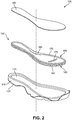
- FIG. 2 is an exploded view of sole structure 105.
- FIG. 2 shows midsole 115 and outer member 120 in an assembled configuration.
- midsole 115 may include a recess 145 configured to contain a cushioning element.
- sole structure 105 may include a chamber 150 for receiving a pressurized fluid. Chamber 150 may be received within recess 145 in midsole 115.
- sole structure 105 may omit the midsole layer between chamber 150 and outer member 120. That is, chamber 150 may be secured directly to outer member 120 of sole structure 105. In some cases, such a configuration may provide sole structure 105 with a lower profile, that is, a reduced height. In some embodiments, midsole 115 may be located above chamber 150. That is, in some cases, chamber 150 may be disposed between midsole 115 and outer member 120.
- sole structure 105 may include an additional component on top of chamber 150.
- sole structure 105 may include a footbed member 185.
- Footbed member 185 may form a covering over top of chamber 150, to conceal chamber 150 from an inner portion of the article of footwear.
- footbed member 185 may provide a surface or footbed configured to support the foot of a wearer directly.
- footbed member 185 may be removable.
- footbed member 185 may be a removable insole/sockliner.
- footbed member 185 may be fixedly attached to one or more portions of the article of footwear.
- footbed member 185 may be fixedly attached to midsole 115 about the periphery of recess 145, thereby enclosing chamber 150.
- footbed member 185 may be a strobel.
- footbed member may be fixedly attached to an upper of the article of footwear.
- footbed member 185 when combined with the upper, may substantially completely enclose the foot of a wearer and isolate the wearer's foot from chamber 150.
- footbed member 185 may include more than one component.
- a footbed member may include both an enclosing upper midsole portion and a strobe element attached to the upper.
- Footbed member 185 may have any suitable configuration and any suitable material.
- footbed member 185 may be substantially incompressible.
- footbed member 185 may be formed of rigid or semi-rigid materials such as hard plastics, carbon fiber, or other composite materials.
- a substantially incompressible footbed member 185 may be formed of a relatively flexible material, such as a textile, leather, or synthetic leather.
- an additional cushioning member such as an insole/sockliner may be utilized on top of footbed member 185.
- footbed member 185 may be formed, at least in part, by a compressible material.
- footbed member 185 may be formed of a compressible foam material. Such a compressible foam material may enable footbed member 185 to conform to the features of a wearer's foot.
- a compressible footbed member 185 may permanently deform to the shape of the wearer's foot.
- the footbed member 185 may be resilient and return to its original shape after the footwear is removed from the wearer's foot.
- FIG. 3 is a more detailed illustration of chamber 150.
- chamber 150 may include a first chamber barrier layer 155 and a second chamber barrier layer 160.
- first chamber barrier layer 155 may be a top barrier layer and second chamber barrier layer 160 may be a bottom barrier layer.
- Second chamber barrier layer 160 may be bonded to first chamber barrier layer 155 about peripheral portions of first chamber barrier layer 155 and second chamber barrier layer 160 to define an interior void between first chamber barrier layer 155 and second chamber barrier layer 160.
- Chamber 150 may be formed from a polymer or other bladder material that provides a sealed barrier for enclosing a fluid.
- the bladder material may be transparent.
- a wide range of polymer materials may be utilized for chamber 150.
- engineering properties of the material e.g., tensile strength, stretch properties, fatigue characteristics, dynamic modulus, and loss tangent
- the ability of the material to prevent the diffusion of the fluid contained by chamber 150 may be considered.
- the outer barrier of chamber 150 may have a thickness of approximately 1.0 millimeter, but the thickness may range from 0.25 to 2.0 millimeters or more, for example.
- chamber 150 examples of polymer materials that may be suitable for chamber 150 include polyurethane, polyester, polyester polyurethane, and polyether polyurethane.
- Chamber 150 may also be formed from a material that includes alternating layers of thermoplastic polyurethane and ethylene-vinyl alcohol copolymer, as disclosed in U.S. Patent Numbers 5,713,141 and 5,952,065 to Mitchell, et al .
- a variation upon this material may also be utilized, wherein a center layer is formed of ethylene-vinyl alcohol copolymer, layers adjacent to the center layer are formed of thermoplastic polyurethane, and outer layers are formed of a regrind material of thermoplastic polyurethane and ethylene-vinyl alcohol copolymer.
- Another suitable material for chamber 150 is a flexible microlayer membrane that includes alternating layers of a gas barrier material and an elastomeric material, as disclosed in U.S. Patent Numbers 6,082,025 and 6,127,026 to Bonk, et al . Additional suitable materials are disclosed in U.S. Patent Numbers 4,183,156 and 4,219,945 to Rudy . Further suitable materials include thermoplastic films containing a crystalline material, as disclosed in U.S. Patent Numbers 4,936,029 and 5,042,176 to Rudy , and polyurethane including a polyester polyol, as disclosed in U.S. Patent Numbers 6,013,340 ; 6,203,868 ; and 6,321,465 to Bonk, et al.
- the fluid within chamber 150 may range in pressure from zero to three-hundred-fifty kilopascals (i.e., approximately fifty-one pounds per square inch) or more.
- a suitable pressure for the fluid may be a substantially ambient pressure. That is, the pressure of the fluid may be within five kilopascals of the ambient pressure of the atmospheric air surrounding footwear 100.
- the pressure of fluid within chamber 150 may be selected to provide desirable performance attributes. For example, higher pressures may provide a more responsive cushioning element, whereas lower pressures may provide more ground force attenuation (a softer cushion).
- the pressure of fluid within chamber 150 may be selected to work in concert with other cushioning elements of footwear 100, such as midsole 115 and footbed member 185.
- chamber 150 may be inflated with substantially pure nitrogen.
- an inflation gas promotes maintenance of the pressure within chamber 150 through diffusion pumping, whereby the deficiency of other gases (besides nitrogen), such as oxygen, within chamber 150 biases the system for inward diffusion of such gasses into chamber 150.
- bladder materials such as those discussed above, may be substantially impermeable to nitrogen, thus preventing the escape of the nitrogen from chamber 150.
- chamber 150 may include octafluorapropane or be any of the gasses disclosed in U.S. Patent Number 4,340,626 to Rudy , such as hexafluoroethane and sulfur hexafluoride, for example.
- chamber 150 may incorporate a valve that permits the individual to adjust the pressure of the fluid.
- chamber 150 may be incorporated into a fluid system, as disclosed in U.S. Patent Number 7,210,249 to Passke, et al.
- the chamber may include one or more features that limit the expansion of the top and bottom portions of the chamber upon inflation.
- the chamber may include one or more tensile structures that link the top portion of the chamber to the bottom portion of the chamber.
- Such tensile structures may be substantially inelastic (or may have a limited elasticity) such that, when the chamber is inflated causing the top and bottom portions of the chamber to be biased apart from one another, the tensile structures limit the distance by which the top and bottom portions may be separated during inflation. Accordingly, the tensile structures may enable the bladder to retain its intended, substantially planar shape.
- a tensile structure such as a tensile member 165 may extend between first chamber barrier layer 155 and second chamber barrier layer 160.
- Tensile member 165 may be bonded to first chamber barrier layer 155 and second chamber barrier layer 160.
- a thermoplastic (hot melt) adhesive may be used to bond tensile member 165 to first chamber barrier layer 155 and second chamber barrier layer 160.
- Tensile member 165 may have a limited elasticity and, therefore, may limit the extent to which first chamber barrier layer 155 and second chamber barrier layer 160 may be expanded away from one another upon inflation of chamber 150.
- first chamber barrier layer 155 and/or second chamber barrier layer 160 may include bulges formed by the prevention of bonding between tensile member 165 and first chamber barrier layer 155 and/or second chamber barrier layer 160. That is, a first portion of first chamber barrier layer 155 and a second portion of tensile member 165 adjacent to the first portion of first chamber barrier layer 155 may be unbonded in an unbonded area. Chamber 150 may include an outwardly extending bulge in the unbonded area. Such a bulge may extend outwardly (e.g., upwardly) from adjacent portions of first chamber barrier layer 155.
- chamber 150 may include anatomical contours. That is, bulges in chamber 150 may correspond with the anatomical contours of corresponding portions of the foot of a wearer.
- chamber 155 may include an anatomical contour formed, at least in part, by the bulges, wherein the anatomical contour is configured to receive a portion of a foot of a wearer.
- such contours may have a standardized size and shape for a given shoe size.
- such contours may be customized to suit a particular wearer's foot.
- the contours may be semi-customized. For example, a wearer may have an option to select a high arch support or a low arch support. Thus, the wearer may customize their footwear by selecting from a plurality of contours of various predetermined shapes and/or sizes.
- anatomical contours may include, for example, a peripheral bulge 170, which may extend around an outer periphery of first chamber barrier layer 155 of chamber 150 and may bulge upward from adjacent portions of first chamber barrier layer 155.
- a toe contour 175 may be incorporated in the forefoot region of chamber 150. Toe contour 175 may extend in a general direction from proximate a medial side 190 of chamber 150 toward a lateral side 195 of chamber 150.
- toe contour 175 may be configured to accommodate one or more toes of a wearer of the article of footwear. For example, as shown in Fig.
- toe contour 175 may have one or more toe-separating contours 176 configured to be disposed at least partially between toes of a wearer. Further, in some embodiments, an arch support bulge 180 may be provided on medial side 190 of first chamber barrier layer 155, in a midfoot region of chamber 150.
- FIG. 4 is a cross-sectional view of chamber 150 taken at section line 4-4 in Fig. 3 , through a heel region of chamber 150.
- tensile member 165 may include a first tensile member layer 200 bonded to first chamber barrier layer 155.
- an upper surface 215 of first tensile member layer 200 may be bonded to a lower surface 220 of first chamber barrier layer 155.
- tensile member 165 may also include a second tensile member layer 205 bonded to second chamber barrier layer 160.
- a lower surface 225 of second tensile member layer 205 may be bonded to an upper surface 230 of second chamber barrier layer 160.
- Tensile member 165 may further include a plurality of tethers 210 connecting first tensile member layer 200 to second tensile member layer 205.
- the outward force of pressurized fluid within chamber 150 places tethers 210 in tension and restrains further outward movement of first tensile member layer 200 and first chamber barrier layer 155 away from second tensile member layer 205 and second chamber barrier layer 160.
- Tensile member 165 may have any configuration suitable for limiting the distance between first chamber barrier layer 155 and second chamber barrier layer 160 of chamber 150 when inflated.
- tensile member 165 may have any of the configurations disclosed in Dua, U.S. Patent No. 8,151,486, issued April 10, 2012 , and entitled “Fluid-Filled Chamber with a Textile Tensile Member;” Peyton et al., U.S. Patent No. 8,479,412, issued July 9, 2013 , and entitled “Tethered Fluid-Filled Chambers;” and Hazenberg et al., U.S. Patent Application Publication No.2013/0266773, published October 10, 2013 , and entitled "Spacer Textile Materials and Methods for Manufacturing the Spacer Textile Materials”.
- tethers 270 may include a plurality of substantially planar slats. In some configurations, such slats may be arranged in a substantially vertical orientation. In other embodiments, such slats may be angled with respect to first chamber barrier layer 155 and second chamber barrier layer 160. Further, such slats may be oriented in any suitable direction. For example, in some embodiments, the slats may be oriented in a substantially lateral direction. In other embodiments, the slats may be oriented in a substantially longitudinal direction. Other orientations are also possible. Tethers 210 may have any of the planar configurations disclosed in Dua, U.S. Patent No. 8,151,486, issued April 10, 2012 , and entitled "Fluid-Filled Chamber with a Textile Tensile Member.”
- tethers 210 may include a plurality of strand-like members having a substantially one-dimensional configuration.
- tethers 210 may each have a length between first tensile member layer 260 and second tensile member 265. This length may be substantially greater than the width or thickness of the one-dimensional tethers.
- Tethers 210 may have any of the one-dimensional configurations disclosed in Peyton et al., U.S. Patent No. 8,479,412, issued July 9, 2013 , and entitled "Tethered Fluid-Filled Chambers.”
- Tethers 210 may be formed of any suitable material.
- tethers 210 may be formed of a polymer material.
- tensile member 165 may be formed of a three-dimensional fabric (3-D fabric).
- Tensile member 165 may be formed as a unitary (i.e., one-piece) textile element having the configuration of a spacer-knit textile.
- a variety of knitting techniques may be utilized to form tensile member 165 and impart a specific configuration (e.g., taper, contour, length, width, thickness) to tensile member 165. In general, knitting involves forming courses and wales of intermeshed loops of a yarn or multiple yarns.
- tensile member 165 may be formed by mechanically-manipulating yarns to form a one-piece textile element that has a particular configuration.
- the two major categories of knitting techniques are weft-knitting and warp-knitting. Whereas a weft-knit fabric utilizes a single yarn within each course, a warp-knit fabric utilizes a different yarn for every stitch in a course.
- tensile member 165 may be formed using double needle bar Raschel knitting.
- tensile member 165 may be formed using configurations disclosed in Hazenberg et al., U.S. Patent Application Publication No.2013/0266773, published October 10, 2013 , and entitled "Spacer Textile Materials and Methods for Manufacturing the Spacer Textile Materials.”
- all of tethers 210 may have substantially the same length, thus providing tensile member 165 with a substantially constant thickness. In other embodiments, tethers 210 may have different lengths.
- first tensile member layer 200 and second tensile member layer 205 may each have a generally continuous and planar configuration. In some embodiments, first tensile member layer 200 and second tensile member layer 205 may be substantially parallel to one another.
- tensile member 165 may have a tapered configuration. For example, in some embodiments, tensile member 165 may have a tapered configuration between heel region 140 and forefoot region 130.
- the lengths of tethers 210 may decrease between the heel region and forefoot region of chamber 150.
- Exemplary tapered chamber configurations are disclosed in Dua, U.S. Patent No. 8,151,486, issued April 10, 2012 , and entitled "Fluid-Filled Chamber with a Textile Tensile Member.”
- first tensile member layer 200 and second tensile member layer 205 may have a contoured configuration.
- first tensile member layer 205 may have a concave configuration to conform to the anatomical shapes of the foot.
- a depression in heel region 140 may cradle the heel of a wearer and more evenly distribute contact forces between chamber 150 and the foot of the wearer.
- Exemplary contoured chamber configurations are disclosed in Dua, U.S. Patent No. 8,151,486, issued April 10, 2012 , and entitled “Fluid-Filled Chamber with a Textile Tensile Member;" and Peyton et al., U.S. Patent No. 8,479,412, issued July 9, 2013 , and entitled “Tethered Fluid-Filled Chambers.”
- a bond inhibiting material may be located between the tensile member and at least one of the chamber barrier layers, thus providing an unbonded area in which the tensile member and the chamber barrier layer may be unbonded.
- the bond inhibiting material may be a material that does not bond with either or both of the tensile member and the chamber barrier layer.
- a thermoplastic adhesive material may be used to bond the tensile member and the chamber barrier layer together. Such a thermoplastic adhesive (hot melt) may be activated by heat to bond these components together.
- the bond inhibiting material may be a material that does not melt or otherwise bond with at least one of the adjacent components during the heating process that activates the thermoplastic adhesive. Accordingly, following the heating process, any portions of the chamber barrier layer that were masked from the thermoplastic adhesive material by a bond inhibiting material will remain unbonded to the tensile member.
- Exemplary bond inhibiting materials may include any suitable materials that prevent bonding between chamber barrier layers and a tensile member.
- the type of bond inhibiting material used may vary according to the type of chamber barrier layer and tensile member used.
- the bond inhibiting material may be a material that does not significantly melt during heating performed to activate adhesive used to bond the chamber barrier layers to the tensile member.
- the bond inhibiting material may be a high temperature polymer.
- heating of the chamber components to bond the chamber barrier layers to the tensile member may be performed using radio frequency (RF) heating.
- exemplary bond inhibiting materials may be RF resistant materials. Examples of such RF resistant materials that may be used as bond inhibiting materials include fiberglass, polytetrafluoroethylene, nylon, cellophane tape, and thermal printing label materials.
- bond inhibiting strips may include an adhesive material on one side.
- bond inhibiting strips may include an adhesive on one side in order to secure the bond inhibiting strips to the chamber barrier layer or to the tensile member.
- Adhesive may be omitted from the opposite side of the bond inhibiting strips in order to prevent the opposite side from being secured to the other component.
- an adhesive may be used to attach a bond inhibiting strip to the hot melt adhesive material sheet used to bond the chamber barrier layer to the tensile member.
- the opposite side of the bond inhibiting strip may be free of adhesive, and further may be formed of a material that does not bond to the chamber barrier layer during heating and/or application of pressure.
- the bond inhibiting material may be transient. That is, the bond inhibiting material may be blended into the adjacent components during the assembly process. For example, in some embodiments, the bond inhibiting material may mix with the adhesive material of the hot melt adhesive sheet and the resulting mixture may soak into the fabric of a tensile member. Accordingly, the final chamber structure may not have a discrete bond inhibiting layer or hot melt adhesive layer.
- the bond inhibiting material may be a liquid material that functions similar to a nonstick cooking spray. By spraying such a bond inhibiting material onto one or more of the chamber layers, bonding may be prevented between such layers.
- peripheral bulge 170 extends on both medial side 190 and lateral side 195 of chamber 150, thereby forming a medial bulge 240 and a lateral bulge 255.
- Medial bulge 240 and lateral bulge 255 extend upward from adjacent portions of first chamber barrier layer 155. Accordingly, medial bulge 240 and lateral bulge 255, when combined with first chamber barrier layer 155 between medial bulge 240 and lateral bulge 255, may form a concavity configured to receive a heel of a wearer. That is, chamber 155 may include a depression, or heel cup, in the heel region of chamber 155.
- medial bulge 240 and/or lateral bulge 255 may form a convexity that, when combined with an outer surface of chamber 150, forms a concavity.
- the concavity formed may be larger (e.g., have a larger general radius of curvature) than the convexity of the bulge.
- a medial bond inhibiting material 235 may be located between first tensile member layer 200 and first chamber barrier layer 155. Consequently, tensile member 165 and first chamber barrier layer 155 are unbonded in an unbonded area corresponding with the location in which medial bond inhibiting material 235 is disposed. As shown in FIG. 4 , in the unbonded area, a medial void 245 may be formed between tensile member 165 and first chamber barrier layer 155 within medial bulge 240. As shown in FIG. 4 , tensile member 165 may be continuous across the unbonded area.
- first chamber barrier layer 155 has a substantially planar configuration in the bonded area in which first chamber barrier layer 155 is bonded to tensile member 165.
- the unbonded area of first chamber barrier layer 155 bulges may outward beyond the plane in which the bonded area of first chamber barrier layer 155 lies.
- the bulged area of chamber 150 has may an increased thickness.
- bonded areas of chamber 150 have a first thickness 270
- unbonded areas of chamber 150 have a second thickness 265 that is greater than the first thickness 270.
- the voids within the bulges may be isolated from the remainder of chamber 150.
- the voids may be inflated separately from the rest of chamber 150.
- the voids may be inflated along with the rest of chamber 150 and then sealed off to isolate the voids.
- the voids within the bulges may be in fluid communication with the remainder of chamber 150. Accordingly, pressurized fluid within chamber 150 may fill and pressurize medial void 245.
- a porous tensile member may be used.
- a fabric tensile member may permit pressurized fluid from chamber 150 to enter into the voids within the bulges formed in the unbonded areas.
- first chamber barrier layer 155 may be substantially inelastic. Accordingly, increasing pressure of the fluid within voids formed by bulges in the chamber barrier layers may not substantially increase the volume, width, or height of medial void 245. Differences in the pressure of the fluid within such voids may vary the compressibility of the bulges. For example, higher pressure within the bulges may decrease the compressibility of the bulges.
- Lateral bulge 255 may be formed by a lateral bond inhibiting material 250. Lateral bond inhibiting material 250 may prevent bonding between first chamber barrier layer 155 and tensile member 165 in an unbonded area. When pressurized, lateral bulge 255 may define a lateral void 260 between first chamber barrier layer 155 and tensile member 165.
- FIG. 5 is a cross-sectional view of the midfoot region of chamber 150 taken at section line 5-5 in FIG. 3 .
- arch support bulge 180 may be disposed on medial side 190 of chamber 150.
- Arch support bulge 180 may be formed by an unbonded area of first chamber barrier layer 155 in which an arch area bond inhibiting strip 275 is disposed between first chamber barrier layer 155 and tensile member 165.
- Arch support bulge 180 may define an arch support bulge void 280.
- lateral bulge 255 may extend into the midfoot region of chamber 150. As shown in FIG. 5 , lateral bulge 255 may extend away from adjacent portions of first chamber barrier layer 155 by a first distance 285. Arch support bulge 180 may extend away from adjacent portions of first chamber barrier layer 155 by a second distance 290. In some embodiments, the thickness of arch support bulge 180 may be greater than lateral bulge 255, and thus, second distance 290 may be greater than first distance 285.
- FIG. 6 is a cross-sectional view of the heel region of chamber 150 taken at section line 6-6 in FIG. 3 .
- medial bulge 240 may have a substantially similar cross-sectional size and/or shape as lateral bulge 255. Accordingly, lateral bulge 255 may extend from adjacent portions of first chamber barrier layer 155 by a first distance 310 and medial bulge 240 may extend from adjacent portions of first chamber barrier layer 155 by a second distance 315 that is substantially the same as first distance 310.
- FIG. 7 shows an exploded view of components of chamber 150 and a mold for joining the chamber components. Further, FIG. 7 illustrates aspects of a method of forming chamber 150. For purposes of illustration, FIG. 7 shows a portion of chamber 150.
- the method of assembling the chamber components may include applying pressure by compressing a stacked arrangement of the components of chamber 150 between a first mold component 335 and a second mold component 340. Accordingly, arranging the plurality of chamber components in a stacked arrangement may involve locating tensile member 165 between first chamber barrier layer 155 and second chamber barrier layer 160.
- the method may include placing the stacked arrangement of chamber components into the first mold.
- the method may further include applying pressure to the stacked arrangement of chamber components to join the chamber components to one another. This compression may be accomplished by applying force with first mold component 335 in a direction indicated by a first arrow 345 and/or by applying an opposite force with second mold component 340 in an opposite direction indicated by a second arrow 350.
- FIG. 7 also shows a first adhesive layer 325 between first chamber barrier layer 155 and first tensile member layer 200 and a second adhesive layer 320 between second chamber barrier layer 160 and second tensile member layer 205.
- First adhesive layer 325 and second adhesive layer 320 may be any suitable adhesive for joining the barrier layers to the tensile member layers.
- first adhesive layer 325 and second adhesive layer 320 may include a hot melt adhesive, such as a thermoplastic material.
- First adhesive layer 325 and second adhesive layer 320 are omitted from other drawings of the application for purposes of clarity.
- the method of assembling the chamber components may include placing a bond inhibiting material 330 between first chamber barrier layer 155 and first adhesive layer 325.
- bond inhibiting material 330 may be located between first adhesive layer 325 and first tensile member layer 200 of tensile member 165. This alternative configuration may also prevent bonding of first chamber barrier layer 155 to tensile member 165.
- bond inhibiting material 330 may be attached, on one side, to a layer of chamber 150.
- bond inhibiting material 330 may include an adhesive material on one side. This may enable bond inhibiting material 330 to be attached to one layer of chamber 150 to preventing undesired shifting of bond inhibiting material 330 during assembly.
- bond inhibiting material 330 may be adhesively attached to a top side of first adhesive layer 325. In such embodiments, bond inhibiting material 330 may inhibit bonding with first chamber barrier layer 155.
- bond inhibiting material 330 may be adhesively attached to first chamber barrier layer 155, and may prevent bonding to first adhesive layer 325.
- bond inhibiting material 330 may be a material that does not bond to first adhesive material 325 when first adhesive material 325 is activated (heated).
- bond inhibiting material 330 may be adhesively attached to a bottom side of first adhesive layer 325, and may inhibit bonding with first tensile member layer 200.
- bond inhibiting material may be adhesively attached to first tensile member layer 200 and may inhibit bonding with first adhesive layer 325.
- Fig. 7 illustrates a schematic representation of the process of assembling chamber 150.
- all layers may be attached in a single compression of the chamber components.
- select components may be attached to one another in a first process to form one or more sub-assemblies, and the sub-assemblies may be joined together in a separate, second process.
- first adhesive layer 325 may be attached to first tensile member layer 200
- second adhesive layer 320 may be attached to second tensile member layer 205 in a preliminary bonding process to form a sub-assembly.
- the sub assembly may then be joined to bond inhibiting material 330, first chamber barrier layer 155, and second chamber barrier layer 160 using heat and compression, for example as shown in Fig. 8 .
- an intermediate step may involve the attachment of bond inhibiting material 330 to a chamber component, such as first adhesive layer 325, prior to executing the bonding process illustrated in Fig. 8 . Exemplary methods of attaching bond inhibiting material to chamber components are discussed in greater detail below with respect to Figs. 16-19 .
- FIG. 8 shows the mold and chamber components shown in FIG. 7 in a compressed condition.
- First mold component 335 has been moved closer to second mold component 340, pressing the chamber components against each other.
- tethers 210 may be in a slack condition, that is, untensioned, as illustrated by the wavy appearance of tethers 210 in FIG. 8 .
- heat may be applied to the chamber components while under compression, in order to facilitate the bonding of the chamber barrier layers to the tensile member.
- joining the chamber components to one another may be performed by applying pressure to the stacked arrangement of chamber components, as described above.
- joining the chamber components to one another may include bonding select portions of first chamber barrier layer 155 to tensile member 165, thereby forming a bonded area and an unbonded area of first chamber barrier layer 155 and tensile member 165.
- a second mold may be used to seal the peripheral portions of the chamber barrier layers.
- the chamber may be inflated with a pressurized fluid. In some embodiments, the inflation may be performed while the chamber resides in the second mold.
- FIG. 9 shows a second mold joining the peripheral portions of the chamber components to one another.
- the second mold may include a third mold component 355 and a fourth mold component 360.
- Third mold component 355 may include a first peripheral mold projection 365 extending toward fourth mold component 360.
- Fourth mold component 360 may include a second peripheral mold projection 370 extending toward third mold component 355.
- a first peripheral barrier layer portion 375 of first chamber barrier layer 155 may be compressed against and joined to a second peripheral barrier layer portion 370 of second chamber barrier layer 160 between first peripheral mold projection 365 and second peripheral mold projection 370.
- chamber 150 may be inflated with a pressurized fluid 385.
- the injection of pressurized fluid 385 may be performed while chamber 150 is compressed within the second mold.
- the top and bottom sides of chamber 150 may be extended up and down, respectively, as indicated by an arrow 390.
- This inflation of chamber 150 may extend tethers 210 and place tethers 210 in tension. This tension is illustrated in FIG. 9 by the substantially straight configuration of tethers 210.
- FIG. 10 shows an assembled, cross-sectional view of a portion of chamber 150.
- first peripheral barrier layer portion 375 of first chamber barrier layer 155 is joined to second peripheral barrier layer portion 380 of second chamber barrier layer 160.
- the joinder of these portions of chamber 150 may form a flange, which may be trimmed after or during the sealing of first peripheral barrier layer portion 375 to second peripheral barrier layer portion 380.
- Tethers 210 of tensile member 165 may extend across the interior void within chamber 150 and are placed in tension by the outward force of the pressurized fluid upon first chamber barrier layer 155 and second chamber barrier layer 160.
- tensile member 165 may prevent chamber 150 from expanding outward, thereby ensuring that the intended shape of chamber 150 is retained.
- the peripheral bond of first peripheral barrier layer portion 375 to second peripheral barrier layer portion 380 joins the polymer sheets to form a seal that prevents the fluid from escaping
- tensile member 165 prevents chamber 150 from expanding outward or otherwise distending due to the pressure of the fluid. That is, tensile member 165 effectively limits the expansion of chamber 150 to retain an intended shape of surfaces of first chamber barrier layer 155 and second chamber barrier layer 160.
- first chamber barrier layer 155 Due to the inclusion of bond inhibiting material 330, a portion of first chamber barrier layer 155 is prevented from bonding with first tensile member layer 200 of tensile member 165. Accordingly, upon pressurization of chamber 150 with a fluid, the unbonded portion of first chamber barrier layer 155 may expand outward, thus forming a first bulge 395 in the outer surface of chamber 150. The pressurized fluid may fill a void 400 within first bulge 395.
- pressurization of chamber 150 may expand a portion of chamber 150 disposed on an opposite side of chamber 150 than bulge 395.
- pressurization may expand a second bulge 401 away from adjacent portions of second chamber barrier layer 160 on the opposite side of chamber 150 from first bulge 395.
- a pressurized fluid will apply even pressure on all interior surfaces of the chamber. This will cause portions of the chamber barrier layers that are not anchored to the opposite side of the chamber to expand outward.
- the distance between first chamber barrier layer 155 and second chamber barrier layer may be limited by the thickness of tensile member 165, which is bonded to the two barrier layers.
- the unbonded areas in which at least one of the chamber barrier layers is not bonded to tensile member 165, there is no structure tying first chamber barrier layer 155 to second chamber barrier layer 160.
- first chamber barrier layer 155 extends outward to form first bulge 395
- second bulge 401 the corresponding portion of second chamber barrier layer 160 opposite first bulge 395 may tend to extend away from adjacent portions of second chamber barrier layer 160, thus forming second bulge 401.
- the area of second chamber barrier layer forming first bulge 401 may be bonded to tensile member 165, that portion of tensile member 165 is not bonded to first chamber barrier layer 155. Accordingly, tensile member 165 is not anchored at the ends of tethers 210 opposite second bulge 401, thus allowing tensile member 165 to deflect with the extension of second chamber barrier layer 160 at second bulge 401.
- first bulge 395 may be substantially the same. In other embodiments, the size and/or shape of first bulge 395 may be at least slightly different from the size and/or shape of second bulge 401. As shown in FIG. 10 , first bulge 395 may have a first width 415 and a first height 405. Second bulge 401 may have a second width 420 and a second height 410. As shown in FIG. 10 , first width 415 of first bulge 395 may be the same or substantially the same as second width 420 of second bulge 401. In some embodiments, however, first width 415 may be different than second width 420. For example, in some embodiments, second width 420 may be smaller than first width 415.
- tensile member 165 since tensile member 165 is bonded to first chamber barrier layer 160, the structure of tensile member 165 proximate to second bulge 401 may restrict the amount to which second chamber barrier layer 160 may bulge outward to form second bulge 401.
- first height 405 of first bulge 395 may be the same or substantially the same as second height 410 of second bulge 401. In other embodiments, however, first height 405 may be different than second height 410.
- second height 410 may be smaller than first height 405. In some embodiments, the smaller second height 410 may be due to the attachment of tensile member 165 to second chamber barrier layer 160, as described above.
- FIG. 11 shows a heel region of another exemplary fluid-filled chamber.
- FIG. 11 shows a chamber 1100 including a first chamber barrier layer 1105 and a second chamber barrier layer 1110.
- Chamber 1100 may also include a tensile member 1115.
- the characteristics of these components may be the same or similar to corresponding components of other embodiments discussed herein.
- chamber 1100 may include an anatomical contour formed by two bulges proximate one another.
- chamber 1100 may include a first elongate bulge 1120 and a second elongate bulge 1125.
- First elongate bulge 1120 and second elongate bulge 1125 may form two arced bulges arranged substantially concentrically about a center portion 1127 of a heel region of chamber 1100. That is, first elongate bulge 1120 and second elongate bulge 1125 may be parallel to one another about the periphery of the heel region.
- elongate bulges having different widths may be disposed proximate to one another.
- a chamber may have a first bulged portion corresponding with a first portion of bond inhibiting material, the first portion of bond inhibiting material having a first width.
- the chamber may include a second bulged portion corresponding with a second portion of bond inhibiting material, the second portion of bond inhibiting material having a second width.
- the first width may be greater than the second width.
- first elongate bulge 1120 may have a first width 1130 and second elongate bulge 1120 may have a second width 1135.
- first width 1130 may be greater than second width 1135, as shown in FIG. 11 .
- FIG. 12 shows a cross-sectional view of a sole structure including the chamber shown in FIG. 11 taken at section line 12-12 in FIG. 11 .
- FIG. 12 also shows a lower portion of a foot 1200.
- the sole structure may include a footbed member 1185 disposed on first chamber barrier portion 1105 of chamber 1100.
- An upper surface 1215 of footbed member 1185 may be configured to receive a lower surface 1220 of foot 1200.
- additional layers such as insoles (sockliners), strobels, sole plates, inner sole boards, and/or midsole layers may be provided above and/or below footbed member 1185.
- tensile member 1115 may include a first tensile member layer 1140, a second tensile member layer 1145, and a plurality of tethers 1150 arranged substantially similarly to other embodiments disclosed herein.
- Chamber 1100 may also include a first bond inhibiting strip 1155 and a second bond inhibiting strip 1165, which may prevent portions of first chamber barrier layer 1105 from bonding with tensile member 1115, thus forming a first void 1160 and a second void 1170, respectively within first elongate bulge 1120 and second elongate bulge 1125.
- FIG. 12 again shows the difference between first width 1130 of first elongate bulge 1120 and second width 1135 of second elongate bulge 1120.
- This difference between first width 1130 of first elongate bulge 1120 and second width 1135 of second elongate bulge 1120 may correspond with a similar difference in width between first bond inhibiting strip 1155 and second bond inhibiting strip 1165.
- the amount to which a bulged portion of a chamber barrier layer extends away from adjacent portions of the chamber barrier layer may correspond with a width of span of the bulged portion.
- a bulged portion may have a length and a width extending in directions that are substantially parallel to a plane substantially containing substantially planar portions of the chamber barrier layer.
- the bulged portion may have a height by which the bulged portion extends away from adjacent portions of the chamber barrier layer.
- the height of the bulged portion may be limited by the shorter of the length and the width of the bulged portion. That is, whichever of the length and the width is shortest will have the most limiting effect on the height of the bulged portion.
- first elongate bulge 1120 may extend from adjacent portions of first chamber barrier layer 1105 by a first distance 1175.
- second elongate bulge 1125 may extend from adjacent portions of first chamber barrier layer 1105 by a second distance 1180.
- first distance 1175 may be greater than second distance 1180. Since first elongate bulge 1120 has a length that is significantly greater than width 1130, the height (first distance 1175) of first elongate bulge 1120 may be determined by first width 1130. Similarly, the height (second distance 1180) of second elongate bulge 1125 may be determined by second width 1135.
- first width 1130 is larger than second width 1135, the height (first distance 1175) of first elongate bulge 1120 may be greater than the height (second distance 1180) of second elongate bulge 1125.
- second elongate bulge 1125 having differing heights proximate to one another chamber 1100 may be provided with a tapering overall thickness.
- footbed member 1185 may have a first peripheral thickness 1190 proximate to a peripheral portion of chamber 1100, and footbed member 1185 may have a second central thickness 1195 proximate to a central portion of chamber 1100.
- first peripheral thickness 1190 may be greater than second central thickness 1195.
- footbed member 1185 may taper from first peripheral thickness 1190 to second central thickness 1195.
- footbed member 1185 may be configured to accommodate first elongate bulge 1120 and second elongate bulge 1125.
- an underside of footbed member 1185 may have one or more pre-formed recesses configured to receive first elongate bulge 1120 and second elongate bulge 1125.
- footbed member 1185 may be formed of a compressible material. In such embodiments, footbed member 1185 may compress to receive first elongate bulge 1120 and second elongate bulge 1125 or any other bulges in chamber 1100, to thereby at least partially conform to the contours of chamber 1100. It will be noted that, the compressibility, flexibility, hardness, and other properties of footbed member 1185 may differ from those of chamber 1100. For example, in some embodiments, footbed member 1185 may be more or less compressible than chamber 1100.
- footbed member 1185 may be more or less compressible than first elongate bulge 1120 and second elongate bulge 1125.
- the less compressible component may provide more control, stability, and support, whereas the more compressible component may provide more cushioning and comfort.
- the combination of components may be configured to provide desired levels of these properties according to activities for which the article of footwear is configured.
- the tapered thickness of chamber 1100 provided by the difference in height of first elongate bulge 1120 and second elongate bulge 1125 may provide a concavity configured to receive the foot of a wearer.
- a first portion 1205 of first elongate bulge 1120 and a second portion 1210 of second elongate bulge 1125 may form a concavity, which, in a cross-section, has an arc 1225.
- arc 1225 may be substantially parallel a curvature of upper surface 1215 of footbed member 1185.
- arc 1225 and upper surface 1215 may have a curvature that is substantially similar to lower surface 1220 of foot 1200.
- FIG. 13 shows an assembled, cross-sectional view of another exemplary fluid-filed chamber embodiment.
- a chamber 1300 may include a first chamber barrier layer 1305 and a second chamber barrier layer 1310.
- Chamber 1300 may also include a tensile member 1315, which may include a first tensile member layer 1320 and a second tensile member layer 1325.
- a plurality of tethers 1330 may extend between first tensile member layer 1320 and second tensile member layer 1325. The characteristics of these components may be the same or similar to corresponding components of other embodiments discussed above.
- chamber 1300 may include bond inhibiting material on opposing sides of chamber 1300. By including bond inhibiting material on opposing sides of the chamber, bulges may be provided on both sides. This may enable chamber 1300 to be formed with a greater amount of contouring. For example, as shown in FIG. 13 , a first bond inhibiting material 1335 may be provided to prevent bonding between first chamber barrier layer 1305 and tensile member 1315. Accordingly, first bond inhibiting material 1335 may form a first bulge 1340. First bulge 1340 may define a first void 1345 filled with the pressurized fluid within chamber 1300. Chamber 1300 may also include a second bond inhibiting material 1355 preventing bonding between second chamber barrier layer 1310 and tensile member 1315.
- Second bond inhibiting material 1355 may form a second bulge 1360, defining a second void 1365.
- first bond inhibiting material 1335 may be the same material as second bond inhibiting material 1355. In other embodiments, first bond inhibiting material 1335 may be a different material than second bond inhibiting material 1355.
- second bulge 1360 may be disposed opposite first bulge 1340.
- first bond inhibiting material 1335 may have substantially the same size and shape as second bond inhibiting material 1355.
- first bulge 1340 and second bulge 1360 may have substantially the same size and shape.
- chamber 1300 may have top and bottom sides with substantial mirror images.
- first bulge 1340 may have a first height 1350 and a first width 1375.
- Second bulge 1360 may have a second height 1370 and a second width 1380.
- first height 1350 may be substantially the same as second height 1370.
- first height 1350 may be different than second height 1370.
- first width 1375 may be substantially the same as second width 1380.
- first width 1375 may be different than second width 1380.
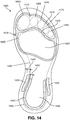
- FIG. 14 shows a top view of a chamber having anatomical contour features.
- a chamber 1400 may include bulges forming anatomical contours. Such bulges may be formed using any of the bond prevention techniques disclosed herein.
- FIG. 14 illustrates a foot of a wearer using dashed lines indicating approximate outlines of portions of the foot.
- chamber 1400 may include a forefoot area bulge 1405 configured to receive forefoot portions of the wearer's foot.
- forefoot area bulge 1405 may substantially encircle a first area 1420 configured to receive the ball of the foot 1485.
- bulge 1405 may define a separate area for receiving the toes of the foot.
- bulge 1405 may include a hallux region 1410 configured to receive a hallux 1460 (first toe) of the foot.
- bulge 1405 may also define a secondary toe region 1415 configured to receive a second toe 1465, a third toe 1470, a fourth toe 1475, and a fifth toe 1480.
- chamber 1400 may include contouring configured to receive portions of a midfoot 1490 of the wearer's foot.
- a substantially U-shaped bulge 1440 may be configured to partially encircle a depression or heel cup area 1455.
- the heel region may further include a medial support bulge 1430 and a lateral support bulge 1435.
- Medial support bulge 1430 and lateral support bulge 1435 may provide additional contouring to accommodate a heel 1495 of a foot.
- medial support bulge 1430 and/or lateral support bulge 1435 may extend further from adjacent portions of chamber 1400 than U-shaped bulge 1440.
- medial bulge 1430 may have a first width 1445 and U-shaped bulge 1440 may have a second width 1450.
- first width 1445 may be greater than second width 1450, thereby providing medial bulge 1430 with a taller profile than U-shaped bulge.
- the heel region of the FIG. 14 configuration may be similar to the embodiment shown in FIG. 12 .
- multiple chambers may be formed simultaneously.
- the various layers of the chamber may be formed from sheets of the respective layer materials.
- multiple chambers may be formed from the same sheets of materials.
- four chambers may be formed from a single stacked arrangement of chamber layers.
- FIG. 15 illustrates an adhesive material sheet 1500.
- Adhesive material sheet 1500 may be a hot melt layer (e.g., thermoplastic), such as first adhesive layer 325 and second adhesive layer 320, as shown in FIG. 7 and discussed above.
- adhesive material sheet 1500 may be configured to be used to form multiple chambers.
- dashed lines indicate approximate outlines illustrating the boundaries of foot-shaped chambers that may be formed from adhesive material sheet 1500.
- FIG. 15 shows a first chamber outline 1505, a second chamber outline 1510, a third chamber outline 1515, and a fourth chamber outline 1520. It will be noted that the number of chambers formed from adhesive material sheet 1500 may vary, and any suitable number of chambers may be formed from a single stacked arrangement of chamber layers.
- bond inhibiting material may be applied to select portions of adhesive material sheet 1500.
- the application of bond inhibiting material may be performed before or after the bonding of adhesive material sheet 1500 to other chamber layers, such as a tensile member.
- bond inhibiting materials may be selectively placed on adhesive material sheet 1500 in a predetermined arrangement corresponding with portions of adhesive material sheet that will be used in forming the chambers.
- a first bond inhibiting material 1525 may be disposed in an area corresponding with first chamber outline 1505.
- a second bond inhibiting material 1530 may be disposed in an area corresponding with second chamber outline 1510.
- a third bond inhibiting material 1535 may be disposed in an area corresponding with third chamber outline 1515.
- a fourth bond inhibiting material 1540 may be disposed in an area corresponding with fourth chamber outline 1520.
- two or more of the bond inhibiting materials applied to adhesive material sheet 1500 may be different may be the same.
- the bond inhibiting materials applied to adhesive material sheet 1500 may be different.
- Bond inhibiting material may be applied to adhesive material sheet 1500 (or other chamber layers, such as chamber barrier layers) using any suitable method.
- bond inhibiting materials may be pre-formed strips that are applied to adhesive material sheet.
- FIG. 16 is a perspective view of a portion of adhesive material sheet 1500.
- FIG. 16 illustrates fourth bond inhibiting material 1540 being applied as a pre-formed strip to adhesive material sheet 1500.
- An arrow 1545 illustrates fourth bond inhibiting material 1540 being applied in a similar manner to a piece of tape.
- bond inhibiting material may be applied to adhesive material sheets (or other chamber layers) using a transfer method.
- applying the bond inhibiting material to the layer of adhesive material may include aligning a transfer sheet including one or more selectively placed strips of bond inhibiting material with a sheet of adhesive material.
- the method may further include pressing the transfer sheet against the sheet of adhesive material, thereby transferring the strip of bond inhibiting material from the transfer sheet to the sheet of adhesive material.
- FIG. 17 illustrates an adhesive material sheet 1700 and a transfer sheet 1705.
- Chamber outlines are shown on adhesive material sheet 1700 in phantom by dashed lines.
- FIG. 17 shows a first chamber outline 1701, a second chamber outline 1702, a third chamber outline 1703, and a fourth chamber outline 1704.
- Adhesive material may be pre-applied to transfer sheet 1705 in select locations.
- a first bond material 1711, a second bond inhibiting material 1712, a third bond inhibiting material 1713, and a fourth bond inhibiting material 1714 may be pre-applied to transfer sheet 1705 in locations that correspond with the chamber outlines of adhesive material sheet 1700.
- transfer sheet 1705 may be pressed against adhesive material sheet 1700. Pressure may transfer the bond inhibiting material onto adhesive material sheet 1700. In some embodiments, the transfer may also be effectuated not only by pressure, but also by the application of heat, water, or other techniques for releasing the bond inhibiting material from transfer sheet 1705.
- FIG. 18 shows a first corner portion 1715 of transfer sheet 1705 being peeled away from a second corner portion 1720 of adhesive material sheet 1700. In the peeled back portion, FIG. 18 illustrates third adhesive material 1713 transferred onto adhesive material sheet 1700. FIG. 18 also shows a phantom outline 1725 indicating where third adhesive material 1713 had been located on transfer sheet 1705.
- applying the bond inhibiting material to the layer of adhesive material may include spraying bond inhibiting material, in liquid form, onto the layer of adhesive material.
- an application device 1555 may be used to apply bond inhibiting material to adhesive material sheet 1500.
- FIG. 19 shows fourth bond inhibiting material 1540 being sprayed onto adhesive material sheet 1500.
- a stencil 1550 may be used to ensure application of bond inhibiting material only to desired locations of adhesive material sheet 1500. In some embodiments, however, bond inhibiting material may be applied by spray application without using a stencil.
- FIG. 20 illustrates a process of cutting an opening 1825 in an adhesive material sheet 1800. Opening 1825 is cut within an area designated for use in forming a chamber. For example, a chamber outline 1805 is shown in phantom by a dashed line.
- Opening 1825 may be formed using any suitable method.
- opening 1825 is cut out of adhesive material sheet 1800.
- Cutting of opening 1825 may be performed using any suitable method.
- a die cutting process may be used to remove a section 1820 of adhesive material layer 1800 to form opening 1825.
- a die 1810 may include a cutting element 1815, which may be formed in the shape of the desired opening to be formed in adhesive material sheet 1800.
- section 1820 of adhesive material sheet 1800 may be cut out, as shown in FIG. 20 .
- FIG. 21 shows a cross-sectional view of an exemplary fluid-filled chamber having a bulge formed by omitting adhesive material in a select location between the chamber barrier layer and the tensile member.
- adhesive material sheet 1800 formed for example using the method shown in FIG. 20 , is used to form a chamber 1830.
- Chamber 1830 includes a first chamber barrier layer 1835 and a second chamber barrier layer 1840.
- a tensile member 1845 extends between first chamber barrier layer 1835 and second chamber barrier layer 1840.
- Tensile member 1845 may include a first tensile member layer 1850, a second tensile member layer 1855, and a plurality of tethers 1860.
- Tensile member 1845 may be configured similarly to other tensile members shown and discussed in other embodiments disclosed herein.
- adhesive material sheet 1800 may bond portions of first chamber barrier layer 1835 to tensile member 1845.
- a second adhesive material sheet 1865 may bond second chamber barrier layer 1840 to tensile member 1845.
- Opening 1825 in adhesive material sheet 1800 forms an unbonded area by preventing bonding of first chamber barrier layer 1835 to tensile member 1845 in the area of opening 1825.
- Chamber 1830 includes an outwardly extending first bulge 1870 in the unbonded area corresponding with the location of opening 1825 in adhesive material sheet 1800. It will be noted that bulges formed in unbonded areas corresponding with openings in adhesive material layers may have any suitable configuration. For example, the anatomical contours shown in other embodiments disclosed herein may be formed in this manner (as opposed to using bond inhibiting material).
- first bulge 1870 may extend from adjacent portions of first chamber barrier layer 1835 by a first distance 1880, thus forming a void 1875 upon pressurization of chamber 1830.
- a second bulge 1885 may be formed opposite first bulge 1870 due to the lack of anchoring of tensile member 1845 opposite second bulge 1885.
- second bulge 1885 may extend from adjacent portions of second chamber barrier layer 1840 by a second distance 1890.
- first distance 1880 may be greater than second distance 1890.
- the bulges may be provided on the lower side of the chamber.
- the lower barrier layer may extend downward creating contours on a lower surface of the chamber. That is, the chambers may be configured with arrangements that are essentially upside down from that shown in the accompanying figures. This may facilitate nesting of the chamber with a contoured midsole and/or outsole.
- the disclosed chamber configurations and tensile member arrangements may be implemented in articles other than footwear.
- such chambers may be used for other articles such as garments and sporting equipment.
- such chambers may be used to provide padding for sports garments, and the disclosed bulges in the chamber may provide contouring that enables the padding to conform to the curvatures of various parts of the body.
- such chambers may be used to provide padding in sports equipment, such as baseball gloves, catchers padding, lacrosse and football pads, and other such equipment.
Landscapes
- Engineering & Computer Science (AREA)
- Mechanical Engineering (AREA)
- Chemical & Material Sciences (AREA)
- Materials Engineering (AREA)
- Footwear And Its Accessory, Manufacturing Method And Apparatuses (AREA)
Claims (14)
- Schuhartikel (100), der einen Oberteil und eine Sohlenstruktur aufweist, die an dem Oberteil befestigt ist, wobei die Sohlenstruktur Folgendes umfasst:eine Kammer (150) zum Aufnehmen eines druckbeaufschlagten Fluids, wobei die Kammer (150) eine erste Kammerbarriereschicht (155) und eine zweite Kammerbarriereschicht (160) aufweist, die so um umlaufende Abschnitte der ersten Kammerbarriereschicht (155) und der zweiten Kammerbarriereschicht (160) an die erste Kammerbarriereschicht (155) gebunden ist, dass ein innerer Hohlraum zwischen der ersten Kammerbarriereschicht (155) und der zweiten Kammerbarriereschicht (160) definiert ist;ein Zugelement (165), das an die erste Kammerbarriereschicht (155) und die zweite Kammerbarriereschicht (160) gebunden ist und sich dazwischen erstreckt; undein bindungshemmendes Material, das sich zwischen dem Zugelement (165) und der ersten Kammerbarriereschicht (155) befindet und sich entlang eines ersten umlaufenden Randes der Kammer (150) in der Nähe einer medialen Seite (190) der Kammer (150) und entlang eines zweiten umlaufenden Randes der Kammer (150) in der Nähe einer lateralen Seite (195) der Kammer (150) erstreckt, wobei das Zugelement (165) und die erste Kammerbarriereschicht (155) in einem ungebundenen Bereich, in dem das bindungshemmende Material angeordnet ist, ungebunden sind;wobei die Kammer (150) eine sich nach außen erstreckende Ausbauchung in dem ungebundenen Bereich umfasst, undund wobei die Ausbauchung sich so auf sowohl der medialen Seite (190) als auch der lateralen Seite (195) der Kammer (150) erstreckt, dass sie eine mediale Ausbauchung (240) und eine laterale Ausbauchung (255) bildet; undwobei die Kammer (150) eine ebene Oberfläche umfasst, die sich in eine erste Richtung zwischen dem bindungshemmenden Material, das sich in der Nähe der medialen Seite (190) befindet, und dem bindungshemmenden Material erstreckt, das sich in der Nähe der lateralen Seite (195) befindet.
- Schuhartikel nach Anspruch 1, wobei die Kammer (150) eine anatomische Kontur umfasst, die zumindest teilweise von der Ausbauchung gebildet ist, wobei die anatomische Kontur so ausgestaltet ist, dass sie einen Abschnitt eines Fußes eines Trägers aufnimmt.
- Schuhartikel nach Anspruch 2, wobei:(1) die anatomische Kontur mindestens eine einer Vertiefung in einer Fersenregion der Kammer (150), einer Gewölbestütze in einer Mittelfußregion der Kammer (150), einer Vertiefung in einer Vorfußregion der Kammer (150) und/oder einer Zehenkontur umfasst, die so ausgestaltet ist, dass sie einen oder mehrere Zehen des Trägers des Schuhartikels unterbringt; oder(2) die anatomische Kontur von zwei gewölbten Ausbauchungen gebildet ist, die im Wesentlichen konzentrisch um einen mittleren Abschnitt einer Fersenregion der Kammer (150) eingerichtet sind.
- Schuhartikel nach Anspruch 1, wobei die Kammer (150) einen ersten ausgebauchten Abschnitt, der einem ersten Abschnitt aus bindungshemmendem Material entspricht, wobei der erste Abschnitt aus bindungshemmendem Material eine erste Breite aufweist, und einen zweiten ausgebauchten Abschnitt umfasst, der einem zweiten Abschnitt aus bindungshemmendem Material entspricht, wobei der zweite Abschnitt aus bindungshemmendem Material eine zweite Breite aufweist, wobei die erste Breite größer als die zweite Breite ist;
wobei der erste ausgebauchte Abschnitt sich über eine erste Distanz von benachbarten Bereichen der Kammer (150) nach außen erstreckt und der zweite ausgebauchte Abschnitt sich über eine zweite Distanz von benachbarten Bereichen der Kammer (150) nach außen erstreckt; und
wobei die erste Distanz größer als die zweite Distanz ist. - Schuhartikel nach Anspruch 1, wobei:(1) die Ausbauchung eine Konvexität bildet, die, wenn sie mit einer äußeren Oberfläche der Kammer (150) kombiniert wird, eine Konkavität bildet;(2) die Ausbauchung eine erste Ausbauchung ist, die sich auf einer Seite der Kammer (150) nach außen erstreckt, wobei die Kammer (150) ferner eine zweite Ausbauchung umfasst, die sich auf einer der ersten Ausbauchung entgegengesetzten Seite der Kammer (150) erstreckt; wobei die Kammerbarriereschicht in dem Bereich der zweiten Ausbauchung an das Zugelement (165) gebunden ist; oder(3) die Ausbauchung eine erste Ausbauchung ist, die einem ersten Abschnitt aus bindungshemmendem Material entspricht und sich über eine erste Distanz von benachbarten Abschnitten der Kammer (150) nach außen erstreckt, wobei die Kammer (150) ferner eine zweite Ausbauchung umfasst, die einem zweiten Abschnitt aus bindungshemmendem Material entspricht und sich über eine zweite Distanz von benachbarten Abschnitten der Kammer (150) in der Nähe der ersten Ausbauchung erstreckt, wobei die zweite Distanz kürzer als die erste Distanz ist, wodurch die Kammer (150) so definiert ist, dass sie eine zugespitzte Dicke aufweist.
- Schuhartikel nach Anspruch 1, wobei die erste Kammerbarriereschicht (155) eine im Wesentlichen ebene Ausgestaltung in einem gebundenen Bereich aufweist, in dem die erste Kammerbarriereschicht (155) an das Zugelement (165) gebunden ist; und
wobei der ungebundene Bereich der ersten Kammerbarriereschicht (155) über eine Ebene, in der der gebundene Bereich der ersten Kammerschicht (155) liegt, nach außen ausgebaucht ist. - Schuhartikel, der einen Oberteil und eine Sohlenstruktur aufweist, die an dem Oberteil befestigt ist, wobei die Sohlenstruktur Folgendes umfasst:eine Kammer (1830) zum Aufnehmen eines druckbeaufschlagten Fluids, wobei die Kammer (1830) eine erste Kammerbarriereschicht (1835) und eine zweite Kammerbarriereschicht (1840) aufweist, die so um umlaufende Abschnitte der ersten Kammerbarriereschicht (1835) und der zweiten Kammerbarriereschicht (1840) an die erste Kammerbarriereschicht (1835) gebunden ist, dass ein innerer Hohlraum zwischen der ersten Kammerbarriereschicht (1835) und der zweiten Kammerbarriereschicht (1840) definiert ist;ein Zugelement (1845), das an die erste Kammerbarriereschicht (1835) und die zweite Kammerbarriereschicht (1840) gebunden ist und sich dazwischen erstreckt;wobei ein erster Abschnitt der ersten Kammerbarriereschicht (1835) und ein zweiter Abschnitt des Zugelements (1845), der dem ersten Abschnitt der ersten Kammerbarriereschicht (1835) benachbart ist, in einem ungebundenen Bereich ungebunden sind;wobei die Kammer (1830) in dem ungebundenen Bereich eine sich nach außen erstreckende Ausbauchung umfasst, undwobei die Ausbauchung sich so auf sowohl der medialen Seite als auch der lateralen Seite der Kammer (1830) erstreckt, dass sie eine mediale Ausbauchung und eine laterale Ausbauchung bildet;wobei das Zugelement (1845) an die erste Kammerbarriereschicht (1835) und die zweite Kammerbarriereschicht (1840) mit einer Schicht aus haftendem Material gebunden ist;wobei die Schicht aus haftendem Material eine Öffnung (1825) umfasst, die den ungebundenen Bereich definiert, in dem die erste Kammerbarriereschicht (1835) und das Zugelement (1845) ungebunden sind;wobei ein erster Abschnitt der Öffnung (1825) sich entlang eines ersten umlaufenden Randes der Kammer (1830) in der Nähe einer medialen Seite der Kammer (1830) erstreckt und ein zweiter Abschnitt der Öffnung sich entlang eines zweiten umlaufenden Randes der Kammer (1830) in der Nähe einer lateralen Seite (195) der Kammer (1830) erstreckt; undwobei die Kammer (1830) eine ebene Oberfläche umfasst, die sich in einer ersten Richtung zwischen dem ersten Abschnitt der Öffnung, der sich in der Nähe der medialen Seite befindet, und dem zweiten Abschnitt der Öffnung erstreckt, der sich in der Nähe der lateralen Seite befindet.
- Schuhartikel nach Anspruch 7, wobei
die Kammer (1830) eine anatomische Kontur umfasst, die zumindest teilweise von der Ausbauchung gebildet ist, wobei die anatomische Kontur so ausgestaltet ist, dass sie einen Abschnitt eines Fußes eines Trägers aufnimmt. - Schuhartikel nach Anspruch 7, wobei:(1) die Kammer (1830) einen ersten ausgebauchten Abschnitt, der einer ersten Öffnung in der Schicht aus haftendem Material entspricht, wobei die erste Öffnung in der Schicht aus haftendem Material eine erste Breite aufweist, und einen zweiten ausgebauchten Abschnitt umfasst, der einer zweiten Öffnung in der Schicht aus haftendem Material entspricht, wobei die zweite Öffnung eine zweite Breite aufweist, wobei die erste Breite größer als die zweite Breite ist;
wobei der erste ausgebauchte Abschnitt sich über eine erste Distanz (1880) von benachbarten Bereichen der Kammer (1830) nach außen erstreckt und der zweite ausgebauchte Abschnitt sich über eine zweite Distanz (1890) von benachbarten Bereichen der Kammer (1830) nach außen erstreckt; und
wobei die erste Distanz (1880) größer ist als die zweite Distanz (1890); oder(2) die Ausbauchung eine erste Ausbauchung (1870) ist, die sich über eine erste Distanz (1880) von benachbarten Abschnitten der Kammer (1830) nach außen erstreckt, wobei die Kammer (1830) ferner eine zweite Ausbauchung (1885) umfasst, die einer zweiten Öffnung in der Schicht aus haftendem Material entspricht und sich über eine zweite Distanz (1890) von benachbarten Abschnitten der Kammer (1830) in der Nähe der ersten Ausbauchung (1870) erstreckt, wobei die zweite Distanz (1890) kürzer als die erste Distanz (1880) ist, wodurch die Kammer (1830) so definiert ist, dass sie eine zugespitzte Dicke aufweist. - Verfahren zum Bilden einer Kammer (150, 1830) zum Aufnehmen eines druckbeaufschlagten Fluids, umfassend:Anordnen einer Vielzahl von Kammerkomponenten in einer gestapelten Anordnung, wobei die Komponenten der Kammer (150, 1830) eine erste Kammerbarriereschicht (155, 1835), eine zweite Kammerbarriereschicht (160, 1840) und ein Zugelement (165, 1845) umfassen, wobei das Anordnen der Komponenten der Kammer (150, 1830) in einer gestapelten Anordnung das Positionieren des Zugelements (165, 1845) zwischen der ersten Kammerbarriereschicht (155, 1835) und der zweiten Kammerbarriereschicht (160, 1840) beinhaltet;Platzieren der gestapelten Anordnung von Kammerkomponenten in einer Form, wobei die Form eine erste Formkomponente und eine zweite Formkomponente umfasst;Verbinden der Komponenten der Kammer (150, 1830) miteinander durch Anwenden von Druck auf die gestapelte Anordnung von Kammerkomponenten;wobei das Verbinden der Komponenten der Kammer (150, 1830) miteinander das Binden gewählter Abschnitte der ersten Kammerbarriereschicht (155, 1835) mit dem Zugelement (165, 1845) umfasst, wodurch ein gebundener Bereich und ein ungebundener Bereich der ersten Kammerbarriereschicht (155, 1835) und des Zugelements (165, 1845) gebildet werden, wobei der ungebundene Bereich sich entlang eines ersten umlaufenden Randes der Kammer (150, 1830) in der Nähe einer medialen Seite (190) der Kammer (150, 1830) und entlang eines zweiten umlaufenden Randes der Kammer (150, 1830) in der Nähe einer lateralen Seite (195) der Kammer (150, 1830) erstreckt, wobei der gebundene Bereich eine ebene Oberfläche umfasst, die sich in einer ersten Richtung zwischen dem ungebundenen Bereich, der sich in der Nähe der medialen Seite (190) der Kammer (150, 1830) befindet, und dem ungebundenen Bereich erstreckt, der sich in der Nähe der lateralen Seite (195) der Kammer (150, 1830) befindet; undAufpumpen der Kammer (150, 1830) mit einem druckbeaufschlagten Fluid, wobei das druckbeaufschlagte Fluid den ungebundenen Bereich der ersten Kammerbarriereschicht (155, 1835) aufweitet, wodurch eine Ausbauchung in einer äußeren Oberfläche der Kammer (150, 1830) gebildet wird, und wobei die Ausbauchung sich so sowohl auf der medialen Seite (190) als auch der lateralen Seite (195) der Kammer (150, 1830) erstreckt, dass eine mediale Ausbauchung (240) und eine laterale Ausbauchung (255) gebildet werden.
- Verfahren nach Anspruch 10, das ferner das Platzieren eines bindungshemmenden Materials zwischen entsprechenden Abschnitten des Zugelements (165, 1845) und der ersten Kammerbarriereschicht (155, 1835) umfasst, sodass das Binden eines gewählten Bereichs des Zugelements (165, 1845) und der ersten Kammerbarriereschicht (155, 1835) verhindert wird, wodurch der ungebundene Bereich gebildet wird.
- Verfahren nach Anspruch 11, das ferner das Aufbringen des bindungshemmenden Materials auf einen Abschnitt einer Schicht aus haftendem Material und das Nutzen der Schicht aus haftendem Material zum Binden des Zugelements (165, 1845) an die erste Kammerbarriereschicht (155, 1835) umfasst, sodass der ungebundene Bereich gebildet wird.
- Verfahren nach Anspruch 12, wobei:(1) das Aufbringen des bindungshemmenden Materials auf die Schicht aus haftendem Material das Ausrichten einer Übertragungslage, die einen selektiv platzierten Streifen des bindungshemmenden Materials umfasst, mit einer Lage des haftenden Materials und das Drücken der Übertragungslage gegen die Lage aus haftendem Material umfasst, wodurch der Streifen aus bindungshemmendem Material von der Übertragungslage auf die Lage aus haftendem Material übertragen wird; oder(2) das Aufbringen des bindungshemmenden Materials auf die Schicht aus haftendem Material das Sprühen von bindungshemmendem Material in flüssiger Form auf die Schicht aus haftendem Material umfasst.
- Verfahren nach Anspruch 10, das ferner das Nutzen einer Schicht aus haftendem Material zum Binden gewählter Bereiche des Zugelements (165, 1845) an entsprechende Bereiche der ersten Kammerbarriereschicht (155, 1835) umfasst;
wobei die Schicht aus haftendem Material eine Öffnung (1825) umfasst; und
wobei die Öffnung (1825) in der Schicht aus haftendem Material das Binden des Zugelements (165, 1845) an die erste Kammerbarriereschicht (155, 1835) in dem Bereich der Öffnung (1825) zum Bilden des ungebundenen Bereichs verhindert.
Applications Claiming Priority (2)
| Application Number | Priority Date | Filing Date | Title |
|---|---|---|---|
| US13/940,738 US9730487B2 (en) | 2013-07-12 | 2013-07-12 | Contoured fluid-filled chamber |
| PCT/US2014/043990 WO2015006048A1 (en) | 2013-07-12 | 2014-06-25 | Contoured fluid-filled chamber |
Publications (2)
| Publication Number | Publication Date |
|---|---|
| EP3019042A1 EP3019042A1 (de) | 2016-05-18 |
| EP3019042B1 true EP3019042B1 (de) | 2021-05-19 |
Family
ID=51220875
Family Applications (1)
| Application Number | Title | Priority Date | Filing Date |
|---|---|---|---|
| EP14742403.0A Active EP3019042B1 (de) | 2013-07-12 | 2014-06-25 | Schuhwerk mit konturierter fluidgefüllter kammer und verfahren zum formen einer konturierten fluidgefüllten kammer |
Country Status (5)
| Country | Link |
|---|---|
| US (5) | US9730487B2 (de) |
| EP (1) | EP3019042B1 (de) |
| KR (1) | KR101835236B1 (de) |
| CN (2) | CN105407754B (de) |
| WO (1) | WO2015006048A1 (de) |
Families Citing this family (46)
| Publication number | Priority date | Publication date | Assignee | Title |
|---|---|---|---|---|
| US9603414B2 (en) * | 2013-03-15 | 2017-03-28 | Nike, Inc. | Fluid-filled chamber with a tensile element |
| US9427043B2 (en) * | 2013-10-31 | 2016-08-30 | Nike, Inc. | Fluid-filled chamber with stitched tensile member |
| US20150265000A1 (en) * | 2014-03-19 | 2015-09-24 | Nike, Inc. | Sole assembly with bladder element having a peripheral outer wall portion and method of manufacturing same |
| US20160302517A1 (en) * | 2015-04-17 | 2016-10-20 | Wolverine World Wide, Inc. | Sole assembly for an article of footwear |
| CN107848159A (zh) * | 2015-07-06 | 2018-03-27 | 轻质复合材料有限公司 | 光固化复合鞋内底 |
| US9907357B2 (en) * | 2015-09-24 | 2018-03-06 | Nike, Inc. | Fluid-filled chamber for an article of footwear |
| CN105394881A (zh) * | 2015-11-27 | 2016-03-16 | 琪尔特有限公司 | 一种跑鞋鞋底 |
| CN206964142U (zh) * | 2016-07-01 | 2018-02-06 | 玛尔塔·埃斯特拉达·维卡洛斯 | 鞋类产品的拟体式鞋内底 |
| CN109475200B9 (zh) * | 2016-07-20 | 2021-09-24 | 耐克创新有限合伙公司 | 鞋板 |
| US10524538B2 (en) * | 2016-09-08 | 2020-01-07 | Nike, Inc. | Flexible fluid-filled chamber with tensile member |
| USD848712S1 (en) * | 2016-12-16 | 2019-05-21 | Plae, Inc. | Outsole of shoe |
| USD822350S1 (en) * | 2017-02-14 | 2018-07-10 | Nike, Inc. | Shoe outsole |
| WO2018157029A1 (en) | 2017-02-27 | 2018-08-30 | Nike Innovate C.V. | Adjustable foot support systems including fluid-filled bladder chambers |
| US10709199B2 (en) * | 2017-03-10 | 2020-07-14 | Nike, Inc. | Footwear sole structure having a fluid-filled chamber including a tensile member |
| US10952496B2 (en) | 2017-05-09 | 2021-03-23 | Under Armour, Inc. | Article of footwear with interlocking midsole member |
| USD826526S1 (en) * | 2017-05-15 | 2018-08-28 | Nike, Inc. | Shoe outsole |
| USD836309S1 (en) * | 2017-05-15 | 2018-12-25 | Under Armour, Inc. | Article of footwear |
| USD898335S1 (en) | 2017-05-16 | 2020-10-13 | Nike, Inc. | Shoe |
| USD882232S1 (en) | 2017-05-16 | 2020-04-28 | Nike, Inc. | Shoe |
| USD897090S1 (en) | 2017-05-16 | 2020-09-29 | Nike, Inc. | Shoe |
| JP2020519343A (ja) * | 2017-05-18 | 2020-07-02 | ナイキ イノベイト シーブイ | 引張コンポーネントを用いたクッション製品およびクッション製品の製造方法 |
| CN114983090A (zh) * | 2017-05-18 | 2022-09-02 | 耐克创新有限合伙公司 | 带有拉伸部件的铰接缓冲垫及制造缓冲垫的方法 |
| USD841954S1 (en) | 2017-06-26 | 2019-03-05 | Nike, Inc. | Shoe outsole |
| KR102359757B1 (ko) * | 2017-11-22 | 2022-02-08 | 나이키 이노베이트 씨.브이. | 신발류 제조용 순응 멤브레인 |
| USD854301S1 (en) | 2018-02-28 | 2019-07-23 | Nike, Inc. | Shoe |
| USD860599S1 (en) | 2018-02-28 | 2019-09-24 | Nike, Inc. | Shoe |
| US11186055B2 (en) * | 2018-03-01 | 2021-11-30 | Nike, Inc. | Method of manufacturing fluid-filled chambers |
| USD862855S1 (en) * | 2018-05-18 | 2019-10-15 | Nike, Inc. | Shoe |
| CN112087964B (zh) | 2018-05-30 | 2022-08-02 | 耐克创新有限合伙公司 | 具有囊的鞋类鞋底结构 |
| CN112512365B (zh) | 2018-05-31 | 2022-04-01 | 耐克创新有限合伙公司 | 包括流体填充囊腔的可调节足部支撑系统 |
| USD879431S1 (en) | 2018-08-03 | 2020-03-31 | Nike, Inc. | Shoe |
| USD879432S1 (en) | 2018-08-03 | 2020-03-31 | Nike, Inc. | Shoe |
| USD880123S1 (en) | 2018-08-03 | 2020-04-07 | Nike, Inc. | Shoe |
| CN112218555A (zh) * | 2018-10-19 | 2021-01-12 | 耐克创新有限合伙公司 | 具有复合元件的鞋类鞋底结构及用于制造其的方法 |
| USD905398S1 (en) * | 2019-07-11 | 2020-12-22 | Nike, Inc. | Shoe |
| USD908331S1 (en) * | 2019-07-11 | 2021-01-26 | Nike, Inc. | Shoe |
| USD885030S1 (en) * | 2019-08-02 | 2020-05-26 | Nike, Inc. | Shoe |
| USD912955S1 (en) * | 2019-08-29 | 2021-03-16 | Nike, Inc. | Shoe |
| USD932756S1 (en) * | 2020-03-25 | 2021-10-12 | Nike, Inc. | Shoe |
| WO2021194727A1 (en) * | 2020-03-26 | 2021-09-30 | Nike Innovate C.V. | Encased strobel with cushioning member and method of manufacturing an article of footwear |
| JP7474092B2 (ja) * | 2020-03-30 | 2024-04-24 | 美津濃株式会社 | シューズ用ソール構造体およびその製造方法、ならびに当該ソール構造体を備えたシューズ |
| US11918074B2 (en) * | 2020-05-12 | 2024-03-05 | Nike, Inc. | Bladder for article of footwear |
| CN114246393A (zh) * | 2020-09-21 | 2022-03-29 | 黄英俊 | 形成曲面的中空物体 |
| US11871812B2 (en) | 2020-10-30 | 2024-01-16 | Nike, Inc. | Cushioning element for article of footwear |
| KR102247770B1 (ko) * | 2021-03-08 | 2021-05-04 | 김만희 | 완충패턴구조를 포함하는 신발바닥재, 및 그 제작방법 |
| WO2023220183A1 (en) * | 2022-05-11 | 2023-11-16 | Nike Innovate C.V. | Footwwear with fiber-reinforced fluid-filled bladder |
Family Cites Families (44)
| Publication number | Priority date | Publication date | Assignee | Title |
|---|---|---|---|---|
| US1869257A (en) | 1929-12-10 | 1932-07-26 | Hitzler Theodor | Insole |
| US3340669A (en) | 1963-01-07 | 1967-09-12 | Dow Chemical Co | Air cushioned packets |
| US4183156A (en) | 1977-01-14 | 1980-01-15 | Robert C. Bogert | Insole construction for articles of footwear |
| US4219945B1 (en) | 1978-06-26 | 1993-10-19 | Robert C. Bogert | Footwear |
| US4976352A (en) * | 1988-06-01 | 1990-12-11 | Samsonite Corporation | Camera bag |
| US4936029A (en) | 1989-01-19 | 1990-06-26 | R. C. Bogert | Load carrying cushioning device with improved barrier material for control of diffusion pumping |
| US5042176A (en) * | 1989-01-19 | 1991-08-27 | Robert C. Bogert | Load carrying cushioning device with improved barrier material for control of diffusion pumping |
| US5245766A (en) * | 1990-03-30 | 1993-09-21 | Nike, Inc. | Improved cushioned shoe sole construction |
| US5564202A (en) * | 1990-05-24 | 1996-10-15 | Hoppenstein; Reuben | Hydropneumatic support system for footwear |
| US5022109A (en) | 1990-06-11 | 1991-06-11 | Dielectrics Industries | Inflatable bladder |
| JP2651434B2 (ja) * | 1991-09-27 | 1997-09-10 | コンバース インコーポレイテッド | クッション作用・安定化装置 |
| US5679439A (en) * | 1992-12-18 | 1997-10-21 | Energaire Corporation | Heel/metatarsal structure having tapered stabilizing bulges |
| US5952065A (en) | 1994-08-31 | 1999-09-14 | Nike, Inc. | Cushioning device with improved flexible barrier membrane |
| TW286269B (de) * | 1994-11-28 | 1996-09-21 | Marion Frank Rudy | |
| US6013340A (en) | 1995-06-07 | 2000-01-11 | Nike, Inc. | Membranes of polyurethane based materials including polyester polyols |
| US5802739A (en) * | 1995-06-07 | 1998-09-08 | Nike, Inc. | Complex-contoured tensile bladder and method of making same |
| EP0884960B1 (de) | 1995-06-07 | 2004-08-18 | Nike International Ltd | Aufgeblasene, verschlossene behälter aus polyesterurethanmembranen und herstellungsverfahren |
| US5741568A (en) * | 1995-08-18 | 1998-04-21 | Robert C. Bogert | Shock absorbing cushion |
| US5993585A (en) * | 1998-01-09 | 1999-11-30 | Nike, Inc. | Resilient bladder for use in footwear and method of making the bladder |
| US6127026A (en) | 1998-09-11 | 2000-10-03 | Nike, Inc. | Flexible membranes |
| US6082025A (en) | 1998-09-11 | 2000-07-04 | Nike, Inc. | Flexible membranes |
| US6571490B2 (en) * | 2000-03-16 | 2003-06-03 | Nike, Inc. | Bladder with multi-stage regionalized cushioning |
| US6402879B1 (en) | 2000-03-16 | 2002-06-11 | Nike, Inc. | Method of making bladder with inverted edge seam |
| US20020194747A1 (en) | 2001-06-21 | 2002-12-26 | Passke Joel L. | Footwear with bladder filter |
| FR2858525B1 (fr) * | 2003-08-05 | 2006-01-27 | Jean Luc Rhenter | Semelle plantaire a amortissement selectif |
| US7070845B2 (en) | 2003-08-18 | 2006-07-04 | Nike, Inc. | Fluid-filled bladder for an article of footwear |
| US7076891B2 (en) * | 2003-11-12 | 2006-07-18 | Nike, Inc. | Flexible fluid-filled bladder for an article of footwear |
| US7234183B2 (en) | 2005-02-08 | 2007-06-26 | Rapid Air Llc | Multiple chamber fluid pressurizable mattress |
| US7622014B2 (en) * | 2005-07-01 | 2009-11-24 | Reebok International Ltd. | Method for manufacturing inflatable footwear or bladders for use in inflatable articles |
| US7409779B2 (en) * | 2005-10-19 | 2008-08-12 | Nike, Inc. | Fluid system having multiple pump chambers |
| US8241451B2 (en) * | 2008-05-20 | 2012-08-14 | Nike, Inc. | Contoured fluid-filled chamber with a tensile member |
| US8151486B2 (en) * | 2008-05-20 | 2012-04-10 | Nike, Inc. | Fluid-filled chamber with a textile tensile member |
| US8943709B2 (en) | 2008-11-06 | 2015-02-03 | Nike, Inc. | Article of footwear with support columns having fluid-filled bladders |
| US8650775B2 (en) * | 2009-06-25 | 2014-02-18 | Nike, Inc. | Article of footwear having a sole structure with perimeter and central elements |
| US8479412B2 (en) * | 2009-12-03 | 2013-07-09 | Nike, Inc. | Tethered fluid-filled chambers |
| JP5835900B2 (ja) * | 2010-01-22 | 2015-12-24 | 賢雄 鄭 | 多機能インソール |
| US8782924B2 (en) * | 2010-05-11 | 2014-07-22 | Nike, Inc. | Article of footwear having a sole structure with a framework-chamber arrangement |
| US8470113B2 (en) | 2010-05-12 | 2013-06-25 | Nike, Inc. | Method of manufacturing a contoured fluid-filled chamber with a tensile member |
| US8464439B2 (en) * | 2010-05-12 | 2013-06-18 | Nike, Inc. | Contoured fluid-filled chamber with a tensile member |
| US8572786B2 (en) * | 2010-10-12 | 2013-11-05 | Reebok International Limited | Method for manufacturing inflatable bladders for use in footwear and other articles of manufacture |
| US9161592B2 (en) * | 2010-11-02 | 2015-10-20 | Nike, Inc. | Fluid-filled chamber with a stacked tensile member |
| US9021720B2 (en) * | 2011-03-16 | 2015-05-05 | Nike, Inc. | Fluid-filled chamber with a tensile member |
| US8789294B2 (en) * | 2011-03-16 | 2014-07-29 | Nike, Inc. | Contoured fluid-filled chamber with tensile structures |
| US9131748B2 (en) * | 2012-04-24 | 2015-09-15 | Nike, Inc. | Sole assembly with gas and viscous fluid-filled bladder assembly |
-
2013
- 2013-07-12 US US13/940,738 patent/US9730487B2/en active Active
-
2014
- 2014-06-25 CN CN201480039290.9A patent/CN105407754B/zh active Active
- 2014-06-25 KR KR1020167003547A patent/KR101835236B1/ko active IP Right Grant
- 2014-06-25 CN CN201811417297.6A patent/CN110074510B/zh active Active
- 2014-06-25 WO PCT/US2014/043990 patent/WO2015006048A1/en active Application Filing
- 2014-06-25 EP EP14742403.0A patent/EP3019042B1/de active Active
-
2017
- 2017-08-07 US US15/670,954 patent/US10376016B2/en active Active
-
2019
- 2019-08-02 US US16/530,120 patent/US11013294B2/en active Active
-
2021
- 2021-05-13 US US17/319,778 patent/US11653715B2/en active Active
-
2023
- 2023-04-18 US US18/302,235 patent/US20230248109A1/en active Pending
Non-Patent Citations (1)
| Title |
|---|
| None * |
Also Published As
| Publication number | Publication date |
|---|---|
| CN110074510A (zh) | 2019-08-02 |
| US20190350311A1 (en) | 2019-11-21 |
| EP3019042A1 (de) | 2016-05-18 |
| US10376016B2 (en) | 2019-08-13 |
| CN105407754B (zh) | 2018-12-25 |
| KR101835236B1 (ko) | 2018-03-06 |
| CN110074510B (zh) | 2021-07-23 |
| US9730487B2 (en) | 2017-08-15 |
| US20170332730A1 (en) | 2017-11-23 |
| US20150013190A1 (en) | 2015-01-15 |
| US20210259360A1 (en) | 2021-08-26 |
| US20230248109A1 (en) | 2023-08-10 |
| KR20160031522A (ko) | 2016-03-22 |
| US11013294B2 (en) | 2021-05-25 |
| US11653715B2 (en) | 2023-05-23 |
| WO2015006048A1 (en) | 2015-01-15 |
| CN105407754A (zh) | 2016-03-16 |
Similar Documents
| Publication | Publication Date | Title |
|---|---|---|
| US11653715B2 (en) | Contoured fluid-filled chamber | |
| US11969049B2 (en) | Flexible fluid-filled chamber with tensile member | |
| US11490687B2 (en) | Fluid-filled chamber with stitched tensile member | |
| US11659890B2 (en) | Flexible fluid-filled chamber with tensile member |
Legal Events
| Date | Code | Title | Description |
|---|---|---|---|
| PUAI | Public reference made under article 153(3) epc to a published international application that has entered the european phase |
Free format text: ORIGINAL CODE: 0009012 |
|
| 17P | Request for examination filed |
Effective date: 20160118 |
|
| AK | Designated contracting states |
Kind code of ref document: A1 Designated state(s): AL AT BE BG CH CY CZ DE DK EE ES FI FR GB GR HR HU IE IS IT LI LT LU LV MC MK MT NL NO PL PT RO RS SE SI SK SM TR |
|
| AX | Request for extension of the european patent |
Extension state: BA ME |
|
| DAX | Request for extension of the european patent (deleted) | ||
| STAA | Information on the status of an ep patent application or granted ep patent |
Free format text: STATUS: EXAMINATION IS IN PROGRESS |
|
| 17Q | First examination report despatched |
Effective date: 20170623 |
|
| GRAP | Despatch of communication of intention to grant a patent |
Free format text: ORIGINAL CODE: EPIDOSNIGR1 |
|
| STAA | Information on the status of an ep patent application or granted ep patent |
Free format text: STATUS: GRANT OF PATENT IS INTENDED |
|
| INTG | Intention to grant announced |
Effective date: 20201204 |
|
| RIN1 | Information on inventor provided before grant (corrected) |
Inventor name: DAVISON, DARREN, C. |
|
| GRAS | Grant fee paid |
Free format text: ORIGINAL CODE: EPIDOSNIGR3 |
|
| GRAA | (expected) grant |
Free format text: ORIGINAL CODE: 0009210 |
|
| STAA | Information on the status of an ep patent application or granted ep patent |
Free format text: STATUS: THE PATENT HAS BEEN GRANTED |
|
| AK | Designated contracting states |
Kind code of ref document: B1 Designated state(s): AL AT BE BG CH CY CZ DE DK EE ES FI FR GB GR HR HU IE IS IT LI LT LU LV MC MK MT NL NO PL PT RO RS SE SI SK SM TR |
|
| REG | Reference to a national code |
Ref country code: GB Ref legal event code: FG4D |
|
| REG | Reference to a national code |
Ref country code: CH Ref legal event code: EP |
|
| REG | Reference to a national code |
Ref country code: DE Ref legal event code: R096 Ref document number: 602014077536 Country of ref document: DE |
|
| REG | Reference to a national code |
Ref country code: AT Ref legal event code: REF Ref document number: 1393153 Country of ref document: AT Kind code of ref document: T Effective date: 20210615 |
|
| REG | Reference to a national code |
Ref country code: IE Ref legal event code: FG4D |
|
| REG | Reference to a national code |
Ref country code: LT Ref legal event code: MG9D |
|
| REG | Reference to a national code |
Ref country code: AT Ref legal event code: MK05 Ref document number: 1393153 Country of ref document: AT Kind code of ref document: T Effective date: 20210519 |
|
| REG | Reference to a national code |
Ref country code: NL Ref legal event code: MP Effective date: 20210519 |
|
| PG25 | Lapsed in a contracting state [announced via postgrant information from national office to epo] |
Ref country code: HR Free format text: LAPSE BECAUSE OF FAILURE TO SUBMIT A TRANSLATION OF THE DESCRIPTION OR TO PAY THE FEE WITHIN THE PRESCRIBED TIME-LIMIT Effective date: 20210519 Ref country code: BG Free format text: LAPSE BECAUSE OF FAILURE TO SUBMIT A TRANSLATION OF THE DESCRIPTION OR TO PAY THE FEE WITHIN THE PRESCRIBED TIME-LIMIT Effective date: 20210819 Ref country code: AT Free format text: LAPSE BECAUSE OF FAILURE TO SUBMIT A TRANSLATION OF THE DESCRIPTION OR TO PAY THE FEE WITHIN THE PRESCRIBED TIME-LIMIT Effective date: 20210519 Ref country code: LT Free format text: LAPSE BECAUSE OF FAILURE TO SUBMIT A TRANSLATION OF THE DESCRIPTION OR TO PAY THE FEE WITHIN THE PRESCRIBED TIME-LIMIT Effective date: 20210519 Ref country code: FI Free format text: LAPSE BECAUSE OF FAILURE TO SUBMIT A TRANSLATION OF THE DESCRIPTION OR TO PAY THE FEE WITHIN THE PRESCRIBED TIME-LIMIT Effective date: 20210519 |
|
| PG25 | Lapsed in a contracting state [announced via postgrant information from national office to epo] |
Ref country code: ES Free format text: LAPSE BECAUSE OF FAILURE TO SUBMIT A TRANSLATION OF THE DESCRIPTION OR TO PAY THE FEE WITHIN THE PRESCRIBED TIME-LIMIT Effective date: 20210519 Ref country code: PL Free format text: LAPSE BECAUSE OF FAILURE TO SUBMIT A TRANSLATION OF THE DESCRIPTION OR TO PAY THE FEE WITHIN THE PRESCRIBED TIME-LIMIT Effective date: 20210519 Ref country code: NO Free format text: LAPSE BECAUSE OF FAILURE TO SUBMIT A TRANSLATION OF THE DESCRIPTION OR TO PAY THE FEE WITHIN THE PRESCRIBED TIME-LIMIT Effective date: 20210819 Ref country code: PT Free format text: LAPSE BECAUSE OF FAILURE TO SUBMIT A TRANSLATION OF THE DESCRIPTION OR TO PAY THE FEE WITHIN THE PRESCRIBED TIME-LIMIT Effective date: 20210920 Ref country code: RS Free format text: LAPSE BECAUSE OF FAILURE TO SUBMIT A TRANSLATION OF THE DESCRIPTION OR TO PAY THE FEE WITHIN THE PRESCRIBED TIME-LIMIT Effective date: 20210519 Ref country code: SE Free format text: LAPSE BECAUSE OF FAILURE TO SUBMIT A TRANSLATION OF THE DESCRIPTION OR TO PAY THE FEE WITHIN THE PRESCRIBED TIME-LIMIT Effective date: 20210519 Ref country code: GR Free format text: LAPSE BECAUSE OF FAILURE TO SUBMIT A TRANSLATION OF THE DESCRIPTION OR TO PAY THE FEE WITHIN THE PRESCRIBED TIME-LIMIT Effective date: 20210820 Ref country code: IS Free format text: LAPSE BECAUSE OF FAILURE TO SUBMIT A TRANSLATION OF THE DESCRIPTION OR TO PAY THE FEE WITHIN THE PRESCRIBED TIME-LIMIT Effective date: 20210919 Ref country code: LV Free format text: LAPSE BECAUSE OF FAILURE TO SUBMIT A TRANSLATION OF THE DESCRIPTION OR TO PAY THE FEE WITHIN THE PRESCRIBED TIME-LIMIT Effective date: 20210519 |
|
| PG25 | Lapsed in a contracting state [announced via postgrant information from national office to epo] |
Ref country code: NL Free format text: LAPSE BECAUSE OF FAILURE TO SUBMIT A TRANSLATION OF THE DESCRIPTION OR TO PAY THE FEE WITHIN THE PRESCRIBED TIME-LIMIT Effective date: 20210519 |
|
| PG25 | Lapsed in a contracting state [announced via postgrant information from national office to epo] |
Ref country code: RO Free format text: LAPSE BECAUSE OF FAILURE TO SUBMIT A TRANSLATION OF THE DESCRIPTION OR TO PAY THE FEE WITHIN THE PRESCRIBED TIME-LIMIT Effective date: 20210519 Ref country code: SM Free format text: LAPSE BECAUSE OF FAILURE TO SUBMIT A TRANSLATION OF THE DESCRIPTION OR TO PAY THE FEE WITHIN THE PRESCRIBED TIME-LIMIT Effective date: 20210519 Ref country code: SK Free format text: LAPSE BECAUSE OF FAILURE TO SUBMIT A TRANSLATION OF THE DESCRIPTION OR TO PAY THE FEE WITHIN THE PRESCRIBED TIME-LIMIT Effective date: 20210519 Ref country code: EE Free format text: LAPSE BECAUSE OF FAILURE TO SUBMIT A TRANSLATION OF THE DESCRIPTION OR TO PAY THE FEE WITHIN THE PRESCRIBED TIME-LIMIT Effective date: 20210519 Ref country code: CZ Free format text: LAPSE BECAUSE OF FAILURE TO SUBMIT A TRANSLATION OF THE DESCRIPTION OR TO PAY THE FEE WITHIN THE PRESCRIBED TIME-LIMIT Effective date: 20210519 Ref country code: DK Free format text: LAPSE BECAUSE OF FAILURE TO SUBMIT A TRANSLATION OF THE DESCRIPTION OR TO PAY THE FEE WITHIN THE PRESCRIBED TIME-LIMIT Effective date: 20210519 |
|
| REG | Reference to a national code |
Ref country code: CH Ref legal event code: PL |
|
| REG | Reference to a national code |
Ref country code: DE Ref legal event code: R097 Ref document number: 602014077536 Country of ref document: DE |
|
| REG | Reference to a national code |
Ref country code: BE Ref legal event code: MM Effective date: 20210630 |
|
| PLBE | No opposition filed within time limit |
Free format text: ORIGINAL CODE: 0009261 |
|
| STAA | Information on the status of an ep patent application or granted ep patent |
Free format text: STATUS: NO OPPOSITION FILED WITHIN TIME LIMIT |
|
| PG25 | Lapsed in a contracting state [announced via postgrant information from national office to epo] |
Ref country code: MC Free format text: LAPSE BECAUSE OF FAILURE TO SUBMIT A TRANSLATION OF THE DESCRIPTION OR TO PAY THE FEE WITHIN THE PRESCRIBED TIME-LIMIT Effective date: 20210519 Ref country code: LU Free format text: LAPSE BECAUSE OF NON-PAYMENT OF DUE FEES Effective date: 20210625 |
|
| 26N | No opposition filed |
Effective date: 20220222 |
|
| PG25 | Lapsed in a contracting state [announced via postgrant information from national office to epo] |
Ref country code: LI Free format text: LAPSE BECAUSE OF NON-PAYMENT OF DUE FEES Effective date: 20210630 Ref country code: IE Free format text: LAPSE BECAUSE OF NON-PAYMENT OF DUE FEES Effective date: 20210625 Ref country code: CH Free format text: LAPSE BECAUSE OF NON-PAYMENT OF DUE FEES Effective date: 20210630 |
|
| PG25 | Lapsed in a contracting state [announced via postgrant information from national office to epo] |
Ref country code: IS Free format text: LAPSE BECAUSE OF FAILURE TO SUBMIT A TRANSLATION OF THE DESCRIPTION OR TO PAY THE FEE WITHIN THE PRESCRIBED TIME-LIMIT Effective date: 20210919 Ref country code: AL Free format text: LAPSE BECAUSE OF FAILURE TO SUBMIT A TRANSLATION OF THE DESCRIPTION OR TO PAY THE FEE WITHIN THE PRESCRIBED TIME-LIMIT Effective date: 20210519 |
|
| PG25 | Lapsed in a contracting state [announced via postgrant information from national office to epo] |
Ref country code: IT Free format text: LAPSE BECAUSE OF FAILURE TO SUBMIT A TRANSLATION OF THE DESCRIPTION OR TO PAY THE FEE WITHIN THE PRESCRIBED TIME-LIMIT Effective date: 20210519 Ref country code: BE Free format text: LAPSE BECAUSE OF NON-PAYMENT OF DUE FEES Effective date: 20210630 |
|
| PG25 | Lapsed in a contracting state [announced via postgrant information from national office to epo] |
Ref country code: HU Free format text: LAPSE BECAUSE OF FAILURE TO SUBMIT A TRANSLATION OF THE DESCRIPTION OR TO PAY THE FEE WITHIN THE PRESCRIBED TIME-LIMIT; INVALID AB INITIO Effective date: 20140625 |
|
| P01 | Opt-out of the competence of the unified patent court (upc) registered |
Effective date: 20230515 |
|
| PG25 | Lapsed in a contracting state [announced via postgrant information from national office to epo] |
Ref country code: CY Free format text: LAPSE BECAUSE OF FAILURE TO SUBMIT A TRANSLATION OF THE DESCRIPTION OR TO PAY THE FEE WITHIN THE PRESCRIBED TIME-LIMIT Effective date: 20210519 |
|
| PGFP | Annual fee paid to national office [announced via postgrant information from national office to epo] |
Ref country code: FR Payment date: 20230510 Year of fee payment: 10 Ref country code: DE Payment date: 20230502 Year of fee payment: 10 |
|
| PGFP | Annual fee paid to national office [announced via postgrant information from national office to epo] |
Ref country code: GB Payment date: 20230504 Year of fee payment: 10 |
|
| PG25 | Lapsed in a contracting state [announced via postgrant information from national office to epo] |
Ref country code: MK Free format text: LAPSE BECAUSE OF FAILURE TO SUBMIT A TRANSLATION OF THE DESCRIPTION OR TO PAY THE FEE WITHIN THE PRESCRIBED TIME-LIMIT Effective date: 20210519 |