EP3018758A1 - Antenna device - Google Patents
Antenna device Download PDFInfo
- Publication number
- EP3018758A1 EP3018758A1 EP14819649.6A EP14819649A EP3018758A1 EP 3018758 A1 EP3018758 A1 EP 3018758A1 EP 14819649 A EP14819649 A EP 14819649A EP 3018758 A1 EP3018758 A1 EP 3018758A1
- Authority
- EP
- European Patent Office
- Prior art keywords
- antenna
- antenna element
- antenna apparatus
- cable
- case
- Prior art date
- Legal status (The legal status is an assumption and is not a legal conclusion. Google has not performed a legal analysis and makes no representation as to the accuracy of the status listed.)
- Withdrawn
Links
Images




Classifications
-
- H—ELECTRICITY
- H01—ELECTRIC ELEMENTS
- H01Q—ANTENNAS, i.e. RADIO AERIALS
- H01Q1/00—Details of, or arrangements associated with, antennas
- H01Q1/08—Means for collapsing antennas or parts thereof
- H01Q1/084—Pivotable antennas
-
- H—ELECTRICITY
- H01—ELECTRIC ELEMENTS
- H01Q—ANTENNAS, i.e. RADIO AERIALS
- H01Q1/00—Details of, or arrangements associated with, antennas
- H01Q1/27—Adaptation for use in or on movable bodies
- H01Q1/32—Adaptation for use in or on road or rail vehicles
- H01Q1/325—Adaptation for use in or on road or rail vehicles characterised by the location of the antenna on the vehicle
- H01Q1/3291—Adaptation for use in or on road or rail vehicles characterised by the location of the antenna on the vehicle mounted in or on other locations inside the vehicle or vehicle body
-
- H—ELECTRICITY
- H01—ELECTRIC ELEMENTS
- H01Q—ANTENNAS, i.e. RADIO AERIALS
- H01Q1/00—Details of, or arrangements associated with, antennas
- H01Q1/48—Earthing means; Earth screens; Counterpoises
-
- H—ELECTRICITY
- H01—ELECTRIC ELEMENTS
- H01Q—ANTENNAS, i.e. RADIO AERIALS
- H01Q21/00—Antenna arrays or systems
- H01Q21/28—Combinations of substantially independent non-interacting antenna units or systems
-
- H—ELECTRICITY
- H01—ELECTRIC ELEMENTS
- H01Q—ANTENNAS, i.e. RADIO AERIALS
- H01Q7/00—Loop antennas with a substantially uniform current distribution around the loop and having a directional radiation pattern in a plane perpendicular to the plane of the loop
- H01Q7/06—Loop antennas with a substantially uniform current distribution around the loop and having a directional radiation pattern in a plane perpendicular to the plane of the loop with core of ferromagnetic material
- H01Q7/08—Ferrite rod or like elongated core
-
- H—ELECTRICITY
- H01—ELECTRIC ELEMENTS
- H01Q—ANTENNAS, i.e. RADIO AERIALS
- H01Q9/00—Electrically-short antennas having dimensions not more than twice the operating wavelength and consisting of conductive active radiating elements
- H01Q9/04—Resonant antennas
- H01Q9/16—Resonant antennas with feed intermediate between the extremities of the antenna, e.g. centre-fed dipole
- H01Q9/20—Two collinear substantially straight active elements; Substantially straight single active elements
- H01Q9/22—Rigid rod or equivalent tubular element or elements
-
- H—ELECTRICITY
- H01—ELECTRIC ELEMENTS
- H01Q—ANTENNAS, i.e. RADIO AERIALS
- H01Q9/00—Electrically-short antennas having dimensions not more than twice the operating wavelength and consisting of conductive active radiating elements
- H01Q9/04—Resonant antennas
- H01Q9/30—Resonant antennas with feed to end of elongated active element, e.g. unipole
Definitions
- the present disclosure relates to an antenna apparatus applicable to an in-vehicle antenna, for example.
- Patent Document 1 As antennas of car navigation apparatuses equipped in vehicles and PNDs (Personal Navigation Devices) mounted on vehicles, there is proposed a film antenna attachable to a front glass or a rear glass (see, for example, Patent Document 1 below).
- Patent Document 1 Japanese Patent Application Laid-open No. Hei 11-017595
- an object of the present disclosure is to provide an antenna apparatus capable of performing a diversity reception and solving the problems described above.
- an antenna apparatus including:
- the first antenna element and the second antenna element it becomes possible to perform a diversity reception. Further, according to at least one embodiment, an antenna apparatus that can be easily attached and has excellent reception performance is provided. Furthermore, by providing the ground element, the ground element and the metal portion are capacitively coupled when the antenna apparatus is used as an in-vehicle antenna. As a result, an area of the portion that functions as the ground is enlarged, and reception characteristics of the antenna can therefore be improved. It should be noted that the effects described herein are not necessarily limited, and any effect described in the present disclosure may be attained. Moreover, the contents of the present disclosure should not be interpreted limitedly by the exemplified effects.
- Fig. 1 shows an example of a structure of an antenna apparatus 10 according to the embodiment.
- the antenna apparatus 10 according to the embodiment is provided inside a vehicle, for example.
- the antenna apparatus 10 receives at least one of broadcast waves and signals transmitted while being superimposed on the broadcast waves.
- the broadcast waves are those of digital terrestrial broadcast that uses a frequency of a UHF band, and the signals transmitted while being superimposed on the broadcast waves are those of data broadcast, for example.
- the antenna apparatus 10 includes, for example, a case 101 obtained by molding a synthetic resin, an antenna element 102, an antenna element 103, a ground element 104, and two coaxial cables (coaxial cable 105 and coaxial cable 106).
- the antenna element 102 as an example of a first antenna element is structured as a wire antenna element that uses a coaxial cable, for example.
- the antenna element 103 as an example of a second antenna element is structured as a stick-type rod antenna element.
- both antenna elements may be constituted of either the wire antenna element or the rod antenna element.
- the antenna element 102 and the antenna element 103 will respectively be referred to as wire antenna element 102 and rod antenna element 103 as appropriate.
- the case 101 Accommodated inside the case 101 is a wiring substrate as an example of a power feed section.
- a heat-resistant ABS resin is used, for example.
- the case 101 includes a main surface 112, a back surface 113 on the other side of the main surface, and four side surfaces (side surface 114, side surface 115, side surface 116, and side surface 117).
- the wire antenna element 102 is connected to the side surface 115
- the rod antenna element 103 is connected to the side surface 114
- the ground element 104 is connected to the side surface 117
- the coaxial cable 105 and the coaxial cable 106 are connected to the side surface 116.
- the rod antenna element 103 is detachable from the case 101.
- the wire antenna element 102 may also be structured to be detachable from the case 101.
- the wire antenna element 102 and the rod antenna element 103 constitute the antenna.
- the antenna apparatus 10 can receive a desired frequency.
- the length of the wire antenna element 102 according to the embodiment is set to be, for example, 12 cm (centimeters), and the length of the rod antenna element 103 is set to be, for example, 10 cm.
- the ground element 104 is constituted of a coaxial cable, for example.
- the length of the ground element 104 is set to be, for example, 11 cm.
- the wire antenna element 102 and the ground element 104 described above are connected to the substrate accommodated inside the case 101 by solder or the like.
- the ground element 104 is bent in a predetermined direction and set in the vicinity of a metal portion of a car body, for example.
- a round plug is attached at a tip end of the coaxial cable 105.
- an audio plug 110 of ⁇ 3.5 mm (millimeters) is attached at a tip end of the coaxial cable 106.
- a 3-prong audio plug 111 of ⁇ 3.5 mm, for example is attached at a tip end of the coaxial cable 106.
- the audio plug 110 and the audio plug 111 are connected to a PND (not shown), for example.
- the coaxial cable 105 and the coaxial cable 106 may be structured as a so-called glasses-type cable in which the cables are formed integrally. Further, as a countermeasure for noises, the coaxial cable 105 and the coaxial cable 106 may be inserted into a ferrite core. The number of times the cables are wound (number of turns) in this case can be set as appropriate.
- Fig. 2 shows an example of the structure of the case 101. It should be noted that in Fig. 2 , illustrations of the antenna elements and the like are partially simplified.
- a wiring substrate 120 is accommodated inside the case 101.
- a ground conductor (earth conductor) 121 is formed directly or via an insulating film.
- the ground conductor 121 is also formed on the back surface of the wiring substrate 120 and is usually connected to the ground conductor 121 on the front surface via a through hole or the like to thus function as a ground.
- the ground element 104 is connected to the ground conductor 121 so that the ground element 104 functions as a common ground of the wire antenna element 102 and the rod antenna element 103.
- connection sections 127, 128, and 129 are formed on the wiring substrate 120.
- the connection section 127 is constituted of, for example, the plug formed at the tip end of the coaxial cable 105 and the jack into which the plug is inserted.
- the connection section 128 is constituted of, for example, the plug formed at the tip end of the coaxial cable 106 and the jack into which the plug is inserted.
- a dipole plug is formed at the tip end of each of the coaxial cable 105 and the coaxial cable 106, for example.
- the jack into which the plug is inserted has a structure corresponding to the plug, that is, a 3-prong jack in this example.
- connection section 129 is constituted of, for example, the plug formed at the tip end of the rod antenna element 103 and the jack into which the plug is inserted.
- a 3-prong plug is formed at the tip end of the rod antenna element 103, for example.
- the jack into which the plug is inserted has a structure corresponding to the plug, that is, a 3-prong jack in this example.
- LNAs (Low Noise Amplifiers) 125 and 126 are formed on the wiring substrate 120.
- the LNAs 125 and 126 are used for improving an S/N ratio (Signal to Noise Ratio) of a reception signal before a demodulation and are each structured by combining circuit devices such as a resistor, a coil, and a transistor as appropriate.
- the wire antenna element 102 is connected to an input section (antenna input) of the LNA 125.
- An output section (power supply/output) of the LNA 125 and the connection section 127 are connected so that power for operating the LNA 125 is supplied from the PND as a connection destination of the coaxial cable 105 to the LNA 125.
- an antenna signal that is received by the wire antenna element 102 and amplified by the LNA 125 is supplied to the PND via the coaxial cable 105.
- the antenna signal is superimposed on a power supply voltage.
- connection section 129 is connected to an input section (antenna input) of the LNA 126.
- An output section (power supply/output) of the LNA 126 and the connection section 129 are connected so that power for operating the LNA 126 is supplied from the PND as a connection destination of the coaxial cable 106 to the LNA 126.
- an antenna signal that is received by the rod antenna element 103 and amplified by the LNA 126 is supplied to the PND via the coaxial cable 106.
- the antenna signal is superimposed on a power supply voltage.
- Fig. 3A is a side view of the rod antenna element 103.
- the rod antenna element 103 includes, for example, an antenna section 130 and a support section 131 that supports the antenna section 130.
- the support section 131 is cylindrical, for example, and one end surface side thereof is connected to the antenna section 130.
- the antenna section 130 is attached while being bent a predetermined angle (e.g., about 45 to 60 degrees) with respect to the support section 131, for example.
- a wire rod 135 constituted of a polyurethane wire (UEW wire) or a coaxial wire is inserted into the antenna section 130 and the support section 131.
- the antenna section 130 and the support section 131 are formed by molding the circumference of the wire rod 135 by a resin, for example.
- a resin for example.
- a heat-resistant PVC (Poly Vinyl Chloride) material, a heat-resistant PP (Poly Propylene) material, or the like is used.
- a plug 132 constituted of an audio plug of ⁇ 3.5 mm is attached, for example.
- a flanged protrusion 133 is formed in the vicinity of the other end surface of the support section 131.
- the protrusion 133 is constituted of a protrusion 133a and a protrusion 133b, for example.
- a jack 140 for attaching the rod antenna element 103 is formed on the side surface 114 of the case 101.
- Fig. 4B shows an example of the structure of the jack 140.
- the jack 140 includes a positioning groove 141 constituted of a groove section 141a and a groove section 141b.
- the rod antenna element 103 By inserting the protrusion 133 into the positioning groove 141, the rod antenna element 103 can be attached to the case 101 in a predetermined positional relationship.
- the attachment angle of the rod antenna element 103 can be adjusted based on the insertion position of the protrusion 133 with respect to the positioning groove 141.
- the attachment angle of the rod antenna element 103 can be differentiated between a case where the protrusion 133a is inserted into the groove section 141a and the protrusion 133b is inserted into the groove section 141b and a case where the protrusion 133a is inserted into the groove section 141b and the protrusion 133b is inserted into the groove section 141a.
- the antenna section 130 and the support section 131 via a rotary mechanism so that the antenna section 130 can rotate while forming an angle of substantially 180 degrees from the end surface of the support section 131.
- the attachment angle of the rod antenna element 103 may be made adjustable by causing the antenna section 130 to rotate.
- the rod antenna element 103 including the bent antenna section 130 is detachable from the case 101.
- the size of the entire antenna apparatus 10 can be made small by detaching the rod antenna element 103 from the case 101, and thus the antenna apparatus 10 can be packed easily in a predetermined box and the like.
- Fig. 5 shows an example of a cross section of the coaxial cable 105.
- An insulator 152 formed of polyethylene and the like covers an outside of an annealed copper wire 151 as an example of an inner conductor, and braided wires 153 are formed on an outer side thereof.
- a ferrite material layer (referred to as ferrite material as appropriate) 154 for mainly preventing noises from the PND is formed.
- An outer coat 155 covers an outside of the ferrite material 154.
- Figs. 6 and 7 each show another example of the cross section of the coaxial cable 105.
- a shield material may be provided for enhancing a shield property with respect to noises.
- a single-sided aluminum foil tape 156 may be provided between the insulator 152 and the braided wires 153.
- the single-sided aluminum foil tape 156 is attached such that an inner surface (surface on insulator 152 side) is an insulating tape and an outer surface (surface on braided wires 153 side) is aluminum.
- the single-sided aluminum foil tape 156 may also be provided between the braided wires 153 and the ferrite material 154.
- the shield material is not limited to an aluminum foil and may be a copper foil.
- Fig. 8A is a graph showing a C/N (Carrier to Noise) ratio of reception signals in a case where an ordinary coaxial cable is used
- Fig. 8B is a graph showing a C/N ratio of reception signals in a case where a coaxial cable including a ferrite material is used.
- the abscissa axis represents a frequency (MHz)
- the ordinate axis represents a signal level (dBm).
- the C/N ratio is expressed by a gap between the signal level and the noise floor level in the graph.
- the noise floor level of Fig. 8B is lower than that of Fig. 8A .
- the coaxial cable that uses the ferrite material has a larger C/N ratio and more favorable reception signal quality than the normal coaxial cable. This is considered to be because the ferrite in the coaxial cable suppresses degradation of the C/N ratio due to the output cable receiving noises radiated from the PND. From the descriptions above, it is favorable to use a ferrite material for the coaxial cable.
- Two antenna apparatuses 10 are used to perform 4 diversity receptions, for example.
- 4 diversity receptions are used when receiving broadcast that uses a high-order modulation system, such as full segment broadcast.
- Fig. 9 is a diagram showing an attachment example of the antenna apparatus 10 to a vehicle.
- the example shown in Fig. 9 shows a case where two antenna apparatuses 10 are set at substantially symmetrical positions (right end and left end) of a dashboard 162 that is in contact with a lower side of a front glass 161 of the vehicle.
- the antenna apparatus 10 at the right end is set on the dashboard 162 while its main surface 112 faces upward.
- the antenna apparatus 10 at the left end is set on the dashboard 162 while its back surface 113 faces upward.
- each of the antenna apparatuses 10 can be used as both the left and right antenna apparatuses 10 by merely inverting the main surface 112 of the case 101.
- the wire antenna element 102 is attached to the dashboard 162 so as to be substantially parallel to the lower side of the front glass 161.
- the wire antenna element 102 is attached to the dashboard 162 using a clamper, an adhesive, a tape, and the like.
- the rod antenna element 103 is positioned in a height direction with respect to the dashboard 162.
- the ground element 104 is attached along the right or left side of the front glass 161.
- Metal bodies hereinafter, referred to as pillars as appropriate
- pillars that connect a vehicle and a vehicle ceiling are provided at the left and right sides of the front glass 161.
- the tip end of the coaxial cable 105 (audio plug 110) and the tip end of the coaxial cable 106 (audio plug 111) are connected to a PND 165.
- a receiver (not shown) is incorporated into the PND 165, and the receiver performs the diversity reception, demodulation, and the like.
- a maximum ratio combining system of a spatial diversity is used as an example of the diversity reception.
- the signals demodulated by the receiver are supplied to a display 166 and the like to be reproduced as a video and audio.
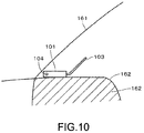
- Fig. 10 is a left side view of the antenna apparatus 10 set at the left end of the dashboard 162.
- the case 101 of the antenna apparatus 10 is attached to the dashboard 162. It should be noted that the case 101 is attached to the dashboard 162 using an adhesive tape, a sucker, or the like.
- the antenna section 130 of the rod antenna element 103 is attached so as to form substantially 45 degrees, for example, instead of a right angle from the support section 131. Therefore, the antenna apparatus 10 can be set on a rear side of the dashboard 162 without causing the rod antenna element 103 to come into contact with the front glass 161.
- a mark may be placed on the front surface of the case 101. For example, arrows indicating the same direction may be placed on the main surface 112 and back surface 113 of the case 101. The user only needs to set the antenna apparatus 10 so that the direction of the arrows matches a traveling direction of the vehicle.
- the ground element 104 By providing the ground element 104 on or in the vicinity of the pillar, the ground element 104 and the pillar are capacitively coupled to thus enlarge the antenna ground. Accordingly, the level of reception signals to be received by the antenna apparatus 10 is raised, and in addition, reception characteristics during traveling are also improved.
- the number of antennas can be easily increased, the diversity reception can be performed with ease.
- Fig. 9 by inverting the case of one of the two antenna apparatuses 10 and appropriately inserting the rod antenna elements, 4 diversity receptions by 4 antenna elements can be performed. Since there is no need to differently structure the antenna apparatuses set on the left- and right-hand sides, a die for producing the antenna apparatuses can be used in common, and costs in mass-producing antenna apparatuses can be reduced.
- Figs. 11 show an example of antenna gain characteristics of a port 1
- Figs. 12 show an example of the antenna gain characteristics of a port 2.
- the port 1 is a level of UHF-band broadcast signals received by the wire antenna element 102 and amplified by the LNA 125
- the port 2 is a level of UHF-band broadcast signals received by the rod antenna element 103 and amplified by the LNA 126.
- the coaxial cable 105 and the coaxial cable 106 having the length of 1.5 m are used.
- Figs. 11A and 12A are graphs, and Figs. 11B and 12B show data.
- the abscissa axis in each of Figs. 11A and 12A represents a frequency (MHz), and the ordinate axis represents a peak gain (dBd).
- the line indicated as "H polarization” indicates frequency-gain characteristics in a horizontal polarization reception
- the line indicated as "V polarization” indicates the frequency-gain characteristics in a vertical polarization reception.
- the gain characteristics of 0 dB or more can generally be obtained in the horizontal polarization as a main polarization of the UHF-band television broadcast.
- Fig. 13 shows measurement graphs regarding a directivity of the wire antenna element 102.
- Fig. 14 shows measurement data regarding the directivity of the wire antenna element 102.
- Fig. 14 shows measurement data in the horizontal polarization reception, measurement data in the vertical polarization reception, and total measurement data.
- Fig. 15 shows measurement graphs regarding a directivity of the rod antenna element 103.
- Fig. 16 shows measurement data regarding the directivity of the rod antenna element 103.
- Fig. 16 shows measurement data in the horizontal polarization reception, measurement data in the vertical polarization reception, and total measurement data. It should be noted that the solid lines in the measurement graphs of Figs. 13 and 15 indicate the directivities in the horizontal polarization reception, and the dotted lines indicate the directivities in the vertical polarization reception.
- the measurement of the directivity was performed every 50 MHz within the range of 470 MHz to 770 MHz. Moreover, the directivity at 906 MHz was measured.
- the measurement of the directivity involves fixing, when measuring a radiation gain, a test antenna device (antenna apparatus 10) to a rotary table and measuring reception power while causing the table and the antenna device to rotate from 0 degree to 360 degrees within a horizontal plane, to measure a gain distribution in the horizontal plane.
- the measurement results shown in the figure are each expressed by a relative gain (unit: dBd) obtained by comparing the antenna gain with that of a half wavelength dipole antenna (maximum gain of 2.15 dBi).
- Fig. 17 schematically shows two orthogonal cross polarizations (vertical polarization and horizontal polarization).
- Fig. 18 shows an example of correlation coefficients of the wire antenna element 102 and the rod antenna element 103. It was confirmed that the correlation coefficients are lower than a setting value. For example, it was confirmed that the correlation coefficients become 0.3 or less.
- an antenna apparatus that has a favorable reception sensitivity and is resistant to noises can be provided. Further, an antenna apparatus that can be set easily can be provided. Furthermore, since the antenna apparatus can be made compact by removing the antenna elements, the antenna apparatus can be packed in a small box or the like with ease.
- the draw-out direction of the coaxial cables is the front glass side.
- the rod antenna element and the coaxial cables may be connected to the same side surface of the case.
- the coaxial cables may be drawn out to a driver side, for example.
- the connection positions of the antenna elements, the ground element, and the coaxial cables with respect to the case can be changed as appropriate.
- the ground element of the embodiment described above may be structured by a rod antenna element, and the ground antenna element may be structured to be detachable from the case.
- the number of groove sections to be formed in the jack of the case is not limited to two.
- two groove sections may be formed on each of the straight intersecting lines, that is, a total of 4 groove sections may be formed.
- the antenna element 102 of the embodiment described above may be structured by a rod antenna element, and the antenna element 102 may be structured to be detachable from the case. In other words, at least one of the antenna element 102 and the antenna element 103 only needs to be detachable from the case. Further, more antenna elements may be connected to the case.
- the cable that outputs reception signals received by the antenna apparatus is not limited to the coaxial cable, and a differential line may be used instead.
- the present disclosure may also take the following structures.
Landscapes
- Engineering & Computer Science (AREA)
- Remote Sensing (AREA)
- Details Of Aerials (AREA)
- Variable-Direction Aerials And Aerial Arrays (AREA)
- Support Of Aerials (AREA)
- Radio Transmission System (AREA)
Abstract
Description
- The present disclosure relates to an antenna apparatus applicable to an in-vehicle antenna, for example.
- As antennas of car navigation apparatuses equipped in vehicles and PNDs (Personal Navigation Devices) mounted on vehicles, there is proposed a film antenna attachable to a front glass or a rear glass (see, for example, Patent Document 1 below).
- Patent Document 1: Japanese Patent Application Laid-open No.
Hei 11-017595 - However, to neatly attach the film antenna at an appropriate position on a window of a vehicle is difficult for general users. In addition, since a material having a sufficient electrical conductivity is not used for the film antenna and an antenna cable is long, there has been a problem that a gain is smaller than that of a rod antenna. As a result, there has been a problem that a use of an amplifier is necessary.
- Therefore, an object of the present disclosure is to provide an antenna apparatus capable of performing a diversity reception and solving the problems described above.
- For solving the problems described above, according to the present disclosure, there is provided an antenna apparatus including:
- a first antenna element and a second antenna element that receive at least one of broadcast waves and signals transmitted while being superimposed on the broadcast waves; and
- a ground element that functions as a common ground of the first antenna element and the second antenna element,
- at least one of the first antenna element and the second antenna element having an adjustable attachment angle.
- By the first antenna element and the second antenna element, it becomes possible to perform a diversity reception. Further, according to at least one embodiment, an antenna apparatus that can be easily attached and has excellent reception performance is provided. Furthermore, by providing the ground element, the ground element and the metal portion are capacitively coupled when the antenna apparatus is used as an in-vehicle antenna. As a result, an area of the portion that functions as the ground is enlarged, and reception characteristics of the antenna can therefore be improved. It should be noted that the effects described herein are not necessarily limited, and any effect described in the present disclosure may be attained. Moreover, the contents of the present disclosure should not be interpreted limitedly by the exemplified effects.
-
- [
Fig. 1 ] A diagram for explaining an example of a structure of an antenna apparatus according to an embodiment. - [
Fig. 2 ] A diagram for explaining an example of a structure of an antenna apparatus according to the embodiment. - [
Figs. 3] Fig. 3A is a diagram for explaining an example of a structure of a rod antenna element according to the embodiment, andFig. 3B is a diagram for explaining an example of a protrusion formed on the rod antenna element. - [
Figs. 4] Figs. 4A and 4B are diagrams for explaining a jack into which a plug of the rod antenna element according to the embodiment is to be inserted. - [
Fig. 5 ] A diagram for explaining an example of a structure of a coaxial cable according to the embodiment. - [
Fig. 6 ] A diagram for explaining another example of the structure of the coaxial cable according to the embodiment. - [
Fig. 7 ] A diagram for explaining another example of the structure of the coaxial cable according to the embodiment. - [
Figs. 8] Fig. 8A is a diagram showing a C/N ratio of signals received by a wire antenna element according to the embodiment, andFig. 8B is a diagram showing a C/N ratio of signals received by the rod antenna element according to the embodiment. - [
Fig. 9 ] A diagram for explaining an arrangement example of the antenna apparatus according to the embodiment. - [
Fig. 10 ] A diagram for explaining an arrangement example of the antenna apparatus according to the embodiment. - [
Figs. 11] Fig. 11A is a graph showing an example of frequency-gain characteristics of the wire antenna element in a UHF band according to the embodiment, and -
Fig. 11B is tables showing an example of gain characteristics at a time the wire antenna element receives a vertical polarization and a horizontal polarization. - [
Figs. 12] Fig. 12A is a graph showing an example of the frequency-gain characteristics of the rod antenna element in the UHF band according to the embodiment, andFig. 12B is tables showing an example of gain characteristics at a time the rod antenna element receives the vertical polarization and the horizontal polarization. - [
Fig. 13 ] A graph showing an example of a directivity of the wire antenna element according to the embodiment. - [
Fig. 14 ] Tables showing measurement data obtained when the directivity of the wire antenna element is measured as an example according to the embodiment. - [
Fig. 15 ] A graph showing an example of a directivity of the rod antenna element according to the embodiment. - [
Fig. 16 ] Tables showing measurement data obtained when the directivity of the rod antenna element is measured as an example according to the embodiment. - [
Fig. 17 ] A diagram schematically showing the vertical polarization and the horizontal polarization. - [
Fig. 18 ] A diagram showing an example of correlation coefficients of the wire antenna element and the rod antenna element. - [
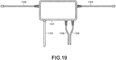
Fig. 19 ] A diagram for explaining a modified example. - [
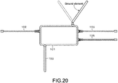
Fig. 20 ] A diagram for explaining a modified example. Modes for Carrying Out the Invention - Hereinafter, an embodiment etc. of the present disclosure will be described with reference to the drawings. It should be noted that the descriptions will be given in the following order.
- The embodiment etc. described below are preferable specific examples of the present disclosure, and contents of the present disclosure should not be limited to the embodiment etc.
- The embodiment of the present disclosure will be described.
Fig. 1 shows an example of a structure of anantenna apparatus 10 according to the embodiment. Theantenna apparatus 10 according to the embodiment is provided inside a vehicle, for example. Theantenna apparatus 10 receives at least one of broadcast waves and signals transmitted while being superimposed on the broadcast waves. The broadcast waves are those of digital terrestrial broadcast that uses a frequency of a UHF band, and the signals transmitted while being superimposed on the broadcast waves are those of data broadcast, for example. - The
antenna apparatus 10 includes, for example, acase 101 obtained by molding a synthetic resin, anantenna element 102, anantenna element 103, aground element 104, and two coaxial cables (coaxial cable 105 and coaxial cable 106). - The
antenna element 102 as an example of a first antenna element is structured as a wire antenna element that uses a coaxial cable, for example. Theantenna element 103 as an example of a second antenna element is structured as a stick-type rod antenna element. Those are of course mere examples, and both antenna elements may be constituted of either the wire antenna element or the rod antenna element. It should be noted that in the descriptions below, theantenna element 102 and theantenna element 103 will respectively be referred to aswire antenna element 102 androd antenna element 103 as appropriate. - Accommodated inside the
case 101 is a wiring substrate as an example of a power feed section. As the material of thecase 101, a heat-resistant ABS resin is used, for example. Thecase 101 includes amain surface 112, aback surface 113 on the other side of the main surface, and four side surfaces (side surface 114,side surface 115,side surface 116, and side surface 117). - Connected to the
case 101 are thewire antenna element 102, therod antenna element 103, theground element 104, thecoaxial cable 105, and thecoaxial cable 106. For example, thewire antenna element 102 is connected to theside surface 115, and therod antenna element 103 is connected to theside surface 114. For example, theground element 104 is connected to theside surface 117, and thecoaxial cable 105 and thecoaxial cable 106 are connected to theside surface 116. - The
rod antenna element 103 is detachable from thecase 101. Thewire antenna element 102 may also be structured to be detachable from thecase 101. - The
wire antenna element 102 and therod antenna element 103 constitute the antenna. By setting the total length obtained by adding the length of thewire antenna element 102 and the length of therod antenna element 103 to be about λ/2 the frequency to be received, theantenna apparatus 10 can receive a desired frequency. The length of thewire antenna element 102 according to the embodiment is set to be, for example, 12 cm (centimeters), and the length of therod antenna element 103 is set to be, for example, 10 cm. - The
ground element 104 is constituted of a coaxial cable, for example. The length of theground element 104 is set to be, for example, 11 cm. Thewire antenna element 102 and theground element 104 described above are connected to the substrate accommodated inside thecase 101 by solder or the like. Theground element 104 is bent in a predetermined direction and set in the vicinity of a metal portion of a car body, for example. - At a tip end of the
coaxial cable 105, a round plug is attached. For example, anaudio plug 110 of ϕ3.5 mm (millimeters) is attached. Similarly, at a tip end of thecoaxial cable 106, a 3-prong audio plug 111 of ϕ3.5 mm, for example, is attached. Theaudio plug 110 and theaudio plug 111 are connected to a PND (not shown), for example. - It should be noted that the
coaxial cable 105 and thecoaxial cable 106 may be structured as a so-called glasses-type cable in which the cables are formed integrally. Further, as a countermeasure for noises, thecoaxial cable 105 and thecoaxial cable 106 may be inserted into a ferrite core. The number of times the cables are wound (number of turns) in this case can be set as appropriate. -
Fig. 2 shows an example of the structure of thecase 101. It should be noted that inFig. 2 , illustrations of the antenna elements and the like are partially simplified. Awiring substrate 120 is accommodated inside thecase 101. On a surface of thewiring substrate 120, a ground conductor (earth conductor) 121 is formed directly or via an insulating film. Theground conductor 121 is also formed on the back surface of thewiring substrate 120 and is usually connected to theground conductor 121 on the front surface via a through hole or the like to thus function as a ground. Theground element 104 is connected to theground conductor 121 so that theground element 104 functions as a common ground of thewire antenna element 102 and therod antenna element 103. -
Connection sections wiring substrate 120. Theconnection section 127 is constituted of, for example, the plug formed at the tip end of thecoaxial cable 105 and the jack into which the plug is inserted. Theconnection section 128 is constituted of, for example, the plug formed at the tip end of thecoaxial cable 106 and the jack into which the plug is inserted. A dipole plug is formed at the tip end of each of thecoaxial cable 105 and thecoaxial cable 106, for example. The jack into which the plug is inserted has a structure corresponding to the plug, that is, a 3-prong jack in this example. - The
connection section 129 is constituted of, for example, the plug formed at the tip end of therod antenna element 103 and the jack into which the plug is inserted. A 3-prong plug is formed at the tip end of therod antenna element 103, for example. The jack into which the plug is inserted has a structure corresponding to the plug, that is, a 3-prong jack in this example. - LNAs (Low Noise Amplifiers) 125 and 126 are formed on the
wiring substrate 120. TheLNAs - The
wire antenna element 102 is connected to an input section (antenna input) of theLNA 125. An output section (power supply/output) of theLNA 125 and theconnection section 127 are connected so that power for operating theLNA 125 is supplied from the PND as a connection destination of thecoaxial cable 105 to theLNA 125. Further, an antenna signal that is received by thewire antenna element 102 and amplified by theLNA 125 is supplied to the PND via thecoaxial cable 105. The antenna signal is superimposed on a power supply voltage. - The
connection section 129 is connected to an input section (antenna input) of theLNA 126. An output section (power supply/output) of theLNA 126 and theconnection section 129 are connected so that power for operating theLNA 126 is supplied from the PND as a connection destination of thecoaxial cable 106 to theLNA 126. Further, an antenna signal that is received by therod antenna element 103 and amplified by theLNA 126 is supplied to the PND via thecoaxial cable 106. The antenna signal is superimposed on a power supply voltage. - An example of the structure of the
rod antenna element 103 will be described.Fig. 3A is a side view of therod antenna element 103. Therod antenna element 103 includes, for example, anantenna section 130 and asupport section 131 that supports theantenna section 130. Thesupport section 131 is cylindrical, for example, and one end surface side thereof is connected to theantenna section 130. Theantenna section 130 is attached while being bent a predetermined angle (e.g., about 45 to 60 degrees) with respect to thesupport section 131, for example. - A
wire rod 135 constituted of a polyurethane wire (UEW wire) or a coaxial wire is inserted into theantenna section 130 and thesupport section 131. Theantenna section 130 and thesupport section 131 are formed by molding the circumference of thewire rod 135 by a resin, for example. As the resin, a heat-resistant PVC (Poly Vinyl Chloride) material, a heat-resistant PP (Poly Propylene) material, or the like is used. - On the other one of the end surfaces (other end surface), a
plug 132 constituted of an audio plug of ϕ3.5 mm is attached, for example. As shown inFig. 3B , aflanged protrusion 133 is formed in the vicinity of the other end surface of thesupport section 131. Theprotrusion 133 is constituted of aprotrusion 133a and aprotrusion 133b, for example. - As shown in
Figs. 4A and 4B , on theside surface 114 of thecase 101, ajack 140 for attaching therod antenna element 103 is formed.Fig. 4B shows an example of the structure of thejack 140. Thejack 140 includes a positioning groove 141 constituted of a groove section 141a and a groove section 141b. - By inserting the
protrusion 133 into the positioning groove 141, therod antenna element 103 can be attached to thecase 101 in a predetermined positional relationship. The attachment angle of therod antenna element 103 can be adjusted based on the insertion position of theprotrusion 133 with respect to the positioning groove 141. For example, the attachment angle of therod antenna element 103 can be differentiated between a case where theprotrusion 133a is inserted into the groove section 141a and theprotrusion 133b is inserted into the groove section 141b and a case where theprotrusion 133a is inserted into the groove section 141b and theprotrusion 133b is inserted into the groove section 141a. - It should be noted that it is also possible to connect the
antenna section 130 and thesupport section 131 via a rotary mechanism so that theantenna section 130 can rotate while forming an angle of substantially 180 degrees from the end surface of thesupport section 131. The attachment angle of therod antenna element 103 may be made adjustable by causing theantenna section 130 to rotate. - It should be noted that in this embodiment, the
rod antenna element 103 including thebent antenna section 130 is detachable from thecase 101. The size of theentire antenna apparatus 10 can be made small by detaching therod antenna element 103 from thecase 101, and thus theantenna apparatus 10 can be packed easily in a predetermined box and the like. - An example of the structure of the
coaxial cable 105 according to the embodiment will be described. It should be noted that the structure of thecoaxial cable 106 is the same. -
Fig. 5 shows an example of a cross section of thecoaxial cable 105. Aninsulator 152 formed of polyethylene and the like covers an outside of an annealedcopper wire 151 as an example of an inner conductor, and braidedwires 153 are formed on an outer side thereof. On the outer side of the braidedwires 153, a ferrite material layer (referred to as ferrite material as appropriate) 154 for mainly preventing noises from the PND is formed. Anouter coat 155 covers an outside of theferrite material 154. -
Figs. 6 and7 each show another example of the cross section of thecoaxial cable 105. A shield material may be provided for enhancing a shield property with respect to noises. For example, as shown inFig. 6 , a single-sidedaluminum foil tape 156 may be provided between theinsulator 152 and the braidedwires 153. The single-sidedaluminum foil tape 156 is attached such that an inner surface (surface oninsulator 152 side) is an insulating tape and an outer surface (surface on braidedwires 153 side) is aluminum. As shown inFig. 7 , the single-sidedaluminum foil tape 156 may also be provided between thebraided wires 153 and theferrite material 154. The shield material is not limited to an aluminum foil and may be a copper foil. -
Fig. 8A is a graph showing a C/N (Carrier to Noise) ratio of reception signals in a case where an ordinary coaxial cable is used, andFig. 8B is a graph showing a C/N ratio of reception signals in a case where a coaxial cable including a ferrite material is used. InFigs. 8A and 8B , the abscissa axis represents a frequency (MHz), and the ordinate axis represents a signal level (dBm). - The C/N ratio is expressed by a gap between the signal level and the noise floor level in the graph. Here, while the signal levels are both around - 70dBm, the noise floor level of
Fig. 8B is lower than that ofFig. 8A . Specifically, the coaxial cable that uses the ferrite material has a larger C/N ratio and more favorable reception signal quality than the normal coaxial cable. This is considered to be because the ferrite in the coaxial cable suppresses degradation of the C/N ratio due to the output cable receiving noises radiated from the PND. From the descriptions above, it is favorable to use a ferrite material for the coaxial cable. - Two
antenna apparatuses 10 are used to perform 4 diversity receptions, for example. 4 diversity receptions are used when receiving broadcast that uses a high-order modulation system, such as full segment broadcast. -
Fig. 9 is a diagram showing an attachment example of theantenna apparatus 10 to a vehicle. The example shown inFig. 9 shows a case where twoantenna apparatuses 10 are set at substantially symmetrical positions (right end and left end) of adashboard 162 that is in contact with a lower side of afront glass 161 of the vehicle. Theantenna apparatus 10 at the right end is set on thedashboard 162 while itsmain surface 112 faces upward. Theantenna apparatus 10 at the left end is set on thedashboard 162 while itsback surface 113 faces upward. As described above, each of theantenna apparatuses 10 can be used as both the left andright antenna apparatuses 10 by merely inverting themain surface 112 of thecase 101. - The
wire antenna element 102 is attached to thedashboard 162 so as to be substantially parallel to the lower side of thefront glass 161. Thewire antenna element 102 is attached to thedashboard 162 using a clamper, an adhesive, a tape, and the like. In a state where thewire antenna element 102 is set on thedashboard 162, therod antenna element 103 is positioned in a height direction with respect to thedashboard 162. - The
ground element 104 is attached along the right or left side of thefront glass 161. Metal bodies (hereinafter, referred to as pillars as appropriate) that connect a vehicle and a vehicle ceiling are provided at the left and right sides of thefront glass 161. - The tip end of the coaxial cable 105 (audio plug 110) and the tip end of the coaxial cable 106 (audio plug 111) are connected to a
PND 165. A receiver (not shown) is incorporated into thePND 165, and the receiver performs the diversity reception, demodulation, and the like. According to the embodiment, a maximum ratio combining system of a spatial diversity is used as an example of the diversity reception. The signals demodulated by the receiver are supplied to adisplay 166 and the like to be reproduced as a video and audio. -
Fig. 10 is a left side view of theantenna apparatus 10 set at the left end of thedashboard 162. Thecase 101 of theantenna apparatus 10 is attached to thedashboard 162. It should be noted that thecase 101 is attached to thedashboard 162 using an adhesive tape, a sucker, or the like. - As described above, the
antenna section 130 of therod antenna element 103 is attached so as to form substantially 45 degrees, for example, instead of a right angle from thesupport section 131. Therefore, theantenna apparatus 10 can be set on a rear side of thedashboard 162 without causing therod antenna element 103 to come into contact with thefront glass 161. It should be noted that for facilitating the setting of theantenna apparatus 10 to thedashboard 162, a mark may be placed on the front surface of thecase 101. For example, arrows indicating the same direction may be placed on themain surface 112 andback surface 113 of thecase 101. The user only needs to set theantenna apparatus 10 so that the direction of the arrows matches a traveling direction of the vehicle. - By providing the
ground element 104 on or in the vicinity of the pillar, theground element 104 and the pillar are capacitively coupled to thus enlarge the antenna ground. Accordingly, the level of reception signals to be received by theantenna apparatus 10 is raised, and in addition, reception characteristics during traveling are also improved. - Further, since the number of antennas can be easily increased, the diversity reception can be performed with ease. As exemplified in
Fig. 9 , by inverting the case of one of the twoantenna apparatuses 10 and appropriately inserting the rod antenna elements, 4 diversity receptions by 4 antenna elements can be performed. Since there is no need to differently structure the antenna apparatuses set on the left- and right-hand sides, a die for producing the antenna apparatuses can be used in common, and costs in mass-producing antenna apparatuses can be reduced. - Furthermore, since 4 diversity receptions can be performed, it becomes possible to receive full segment broadcast and display high-definition letters and videos on the display. In addition, since there is no need to attach an antenna outside the vehicle, it becomes possible to prevent an outer appearance of the vehicle from becoming poor.
-
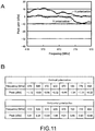
Figs. 11 show an example of antenna gain characteristics of a port 1, andFigs. 12 show an example of the antenna gain characteristics of a port 2. The port 1 is a level of UHF-band broadcast signals received by thewire antenna element 102 and amplified by theLNA 125, and the port 2 is a level of UHF-band broadcast signals received by therod antenna element 103 and amplified by theLNA 126. It should be noted that thecoaxial cable 105 and thecoaxial cable 106 having the length of 1.5 m are used. -
Figs. 11A and12A are graphs, andFigs. 11B and12B show data. The abscissa axis in each ofFigs. 11A and12A represents a frequency (MHz), and the ordinate axis represents a peak gain (dBd). In the graphs, the line indicated as "H polarization" indicates frequency-gain characteristics in a horizontal polarization reception, and the line indicated as "V polarization" indicates the frequency-gain characteristics in a vertical polarization reception. - As can be seen from
Figs. 11 and12 , by applying the LNAs, it was confirmed that the gain characteristics of 0 dB or more can generally be obtained in the horizontal polarization as a main polarization of the UHF-band television broadcast. -
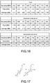
Fig. 13 shows measurement graphs regarding a directivity of thewire antenna element 102.Fig. 14 shows measurement data regarding the directivity of thewire antenna element 102.Fig. 14 shows measurement data in the horizontal polarization reception, measurement data in the vertical polarization reception, and total measurement data. -
Fig. 15 shows measurement graphs regarding a directivity of therod antenna element 103.Fig. 16 shows measurement data regarding the directivity of therod antenna element 103.Fig. 16 shows measurement data in the horizontal polarization reception, measurement data in the vertical polarization reception, and total measurement data. It should be noted that the solid lines in the measurement graphs ofFigs. 13 and15 indicate the directivities in the horizontal polarization reception, and the dotted lines indicate the directivities in the vertical polarization reception. - The measurement of the directivity was performed every 50 MHz within the range of 470 MHz to 770 MHz. Moreover, the directivity at 906 MHz was measured. The measurement of the directivity involves fixing, when measuring a radiation gain, a test antenna device (antenna apparatus 10) to a rotary table and measuring reception power while causing the table and the antenna device to rotate from 0 degree to 360 degrees within a horizontal plane, to measure a gain distribution in the horizontal plane. The measurement results shown in the figure are each expressed by a relative gain (unit: dBd) obtained by comparing the antenna gain with that of a half wavelength dipole antenna (maximum gain of 2.15 dBi).
-
Fig. 17 schematically shows two orthogonal cross polarizations (vertical polarization and horizontal polarization). - From
Figs. 13 and15 , it was confirmed that the directivities of thewire antenna element 102 and therod antenna element 103 differ and that the elements compensate for the differences. Specifically, it was confirmed that a null point of thewire antenna element 102 is compensated by therod antenna element 103, and a null point of therod antenna element 103 is compensated by thewire antenna element 102. As a result, null points of theentire antenna apparatus 10 can be reduced, and a diversity function can be realized. -
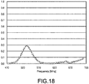
Fig. 18 shows an example of correlation coefficients of thewire antenna element 102 and therod antenna element 103. It was confirmed that the correlation coefficients are lower than a setting value. For example, it was confirmed that the correlation coefficients become 0.3 or less. - As described above, according to the embodiment of the present disclosure, an antenna apparatus that has a favorable reception sensitivity and is resistant to noises can be provided. Further, an antenna apparatus that can be set easily can be provided. Furthermore, since the antenna apparatus can be made compact by removing the antenna elements, the antenna apparatus can be packed in a small box or the like with ease.
- Heretofore, the embodiment of the present disclosure has been specifically described. However, the present disclosure is not limited to the embodiment described above and can be variously modified based on the technical idea of the present disclosure.
- In the embodiment above, the draw-out direction of the coaxial cables is the front glass side. However, as shown in
Fig. 19 , the rod antenna element and the coaxial cables may be connected to the same side surface of the case. The coaxial cables may be drawn out to a driver side, for example. As described above, the connection positions of the antenna elements, the ground element, and the coaxial cables with respect to the case can be changed as appropriate. - The ground element of the embodiment described above may be structured by a rod antenna element, and the ground antenna element may be structured to be detachable from the case. The number of groove sections to be formed in the jack of the case is not limited to two. For example, two groove sections may be formed on each of the straight intersecting lines, that is, a total of 4 groove sections may be formed. By switching the combination of the groove sections into which the protrusion is to be inserted as shown in
Fig. 20 , the position of the ground element can be adjusted. As a result, it becomes possible to switch the attachment angle of the ground element based on the angle of the pillars of the vehicle, for example. Also, a plurality of ground elements may be connected to the case. - The
antenna element 102 of the embodiment described above may be structured by a rod antenna element, and theantenna element 102 may be structured to be detachable from the case. In other words, at least one of theantenna element 102 and theantenna element 103 only needs to be detachable from the case. Further, more antenna elements may be connected to the case. The cable that outputs reception signals received by the antenna apparatus is not limited to the coaxial cable, and a differential line may be used instead. - It should be noted that the structures and processing of the embodiment and modified example can be combined as appropriate unless a technical contradiction is not caused. The order of processing in the exemplified flow of processing can be changed as appropriate unless a technical contradiction is not caused. The numerical values, materials, measurement methods, and the like of the embodiment are mere examples and can be changed as appropriate.
- The present disclosure may also take the following structures.
- (1) An antenna apparatus, including:
- a first antenna element and a second antenna element that receive at least one of broadcast waves and signals transmitted while being superimposed on the broadcast waves; and
- a ground element that functions as a common ground of the first antenna element and the second antenna element,
- at least one of the first antenna element and the second antenna element having an adjustable attachment angle.
- (2) The antenna apparatus according to (1),
in which the second antenna element is, in a state where the first antenna element is set on a predetermined surface, positioned in a height direction with respect to the predetermined surface. - (3) The antenna apparatus according to (2),
in which the predetermined surface is a dashboard of a vehicle. - (4) The antenna apparatus according to any one of (1) to (3),
in which the ground element is capacitively coupled with a metal portion of a vehicle body in which the antenna apparatus is set. - (5) The antenna apparatus according to any one of (1) to (4), further including
a power feed section to which the first antenna element, the second antenna element, and the ground element are connected and that extracts signals received by the first antenna element and the second antenna element. - (6) The antenna apparatus according to (5),
in which the power feed section is accommodated in a predetermined case, and
in which at least one of the first antenna element and the second antenna element is detachable from the case. - (7) The antenna apparatus according to (6),
in which at least one of the first antenna element and the second antenna element is attached to the case via a round connector. - (8) The antenna apparatus according to (6) or (7),
in which the antenna apparatus can be used while a main surface of the case is inverted. - (9) The antenna apparatus according to (8),
in which the main surface and a surface on the other side of the main surface have marks indicating a setting direction of the antenna apparatus. - (10) The antenna apparatus according to any one of (1) to (9),
in which a correlation coefficient of the first antenna element and the second antenna element is smaller than a setting value when the first antenna element and the second antenna element are in a predetermined setting state. - (11) The antenna apparatus according to any one of (5) to (10),
in which a first amplifier connected to the first antenna element and a second amplifier connected to the second antenna element are formed on the power feed section. - (12) The antenna apparatus according to any one of (5) to (11),
in which a cable for transmitting the signals is connected to the power feed section, and
in which the cable includes a ferrite material. - (13) The antenna apparatus according to (12),
in which the cable is structured as a coaxial cable, and the ferrite material covers an outer side of mesh wires. - (14) The antenna apparatus according to (13),
in which a metal foil tape is used for the cable. - (15) The antenna apparatus according to any one of (5) to (11),
in which a cable for transmitting the signals is connected to the power feed section, and
in which the cable is constituted of a differential line. -
- 10
- antenna apparatus
- 101
- case
- 102
- wire antenna element
- 103
- rod antenna element
- 104
- ground element
- 105
- coaxial cable
- 106
- coaxial cable
- 112
- main surface
- 120
- wiring substrate
- 125
- LNA
- 126
- LNA
- 130
- antenna section
- 131
- support section
- 153
- braided wires
- 154
- ferrite material
- 156
- single-sided aluminum foil tape
- 162
- dashboard
Claims (15)
- An antenna apparatus, comprising:a first antenna element and a second antenna element that receive at least one of broadcast waves and signals transmitted while being superimposed on the broadcast waves; anda ground element that functions as a common ground of the first antenna element and the second antenna element,at least one of the first antenna element and the second antenna element having an adjustable attachment angle.
- The antenna apparatus according to claim 1,
wherein the second antenna element is, in a state where the first antenna element is set on a predetermined surface, positioned in a height direction with respect to the predetermined surface. - The antenna apparatus according to claim 2,
wherein the predetermined surface is a dashboard of a vehicle. - The antenna apparatus according to claim 1,
wherein the ground element is capacitively coupled with a metal portion of a vehicle body in which the antenna apparatus is set. - The antenna apparatus according to claim 1, further comprising
a power feed section to which the first antenna element, the second antenna element, and the ground element are connected and that extracts signals received by the first antenna element and the second antenna element. - The antenna apparatus according to claim 5,
wherein the power feed section is accommodated in a predetermined case, and
wherein at least one of the first antenna element and the second antenna element is detachable from the case. - The antenna apparatus according to claim 6,
wherein at least one of the first antenna element and the second antenna element is attached to the case via a round connector. - The antenna apparatus according to claim 6,
wherein the antenna apparatus can be used while a main surface of the case is inverted. - The antenna apparatus according to claim 8,
wherein the main surface and a surface on the other side of the main surface have marks indicating a setting direction of the antenna apparatus. - The antenna apparatus according to claim 1,
wherein a correlation coefficient of the first antenna element and the second antenna element is smaller than a setting value when the first antenna element and the second antenna element are in a predetermined setting state. - The antenna apparatus according to claim 5,
wherein a first amplifier connected to the first antenna element and a second amplifier connected to the second antenna element are formed on the power feed section. - The antenna apparatus according to claim 5,
wherein a cable for transmitting the signals is connected to the power feed section, and
wherein the cable includes a ferrite material. - The antenna apparatus according to claim 12,
wherein the cable is structured as a coaxial cable, and the ferrite material covers an outer side of mesh wires. - The antenna apparatus according to claim 13,
wherein a metal foil tape is used for the cable. - The antenna apparatus according to claim 5,
wherein a cable for transmitting the signals is connected to the power feed section, and
wherein the cable is constituted of a differential line.
Applications Claiming Priority (2)
| Application Number | Priority Date | Filing Date | Title |
|---|---|---|---|
| JP2013139111A JP6067495B2 (en) | 2013-07-02 | 2013-07-02 | Antenna device and in-vehicle electronic device |
| PCT/JP2014/002384 WO2015001696A1 (en) | 2013-07-02 | 2014-05-01 | Antenna device |
Publications (2)
| Publication Number | Publication Date |
|---|---|
| EP3018758A1 true EP3018758A1 (en) | 2016-05-11 |
| EP3018758A4 EP3018758A4 (en) | 2017-03-01 |
Family
ID=52143303
Family Applications (1)
| Application Number | Title | Priority Date | Filing Date |
|---|---|---|---|
| EP14819649.6A Withdrawn EP3018758A4 (en) | 2013-07-02 | 2014-05-01 | Antenna device |
Country Status (6)
| Country | Link |
|---|---|
| US (1) | US20160372814A1 (en) |
| EP (1) | EP3018758A4 (en) |
| JP (1) | JP6067495B2 (en) |
| CN (1) | CN105359340A (en) |
| BR (1) | BR112015032135A8 (en) |
| WO (1) | WO2015001696A1 (en) |
Cited By (1)
| Publication number | Priority date | Publication date | Assignee | Title |
|---|---|---|---|---|
| CN113421389A (en) * | 2021-06-23 | 2021-09-21 | 深圳市中天迅通信技术股份有限公司 | Antenna device for POS machine |
Families Citing this family (6)
| Publication number | Priority date | Publication date | Assignee | Title |
|---|---|---|---|---|
| JP5444786B2 (en) * | 2009-03-30 | 2014-03-19 | ソニー株式会社 | Receiver |
| JP5861455B2 (en) * | 2011-12-28 | 2016-02-16 | ソニー株式会社 | Antenna device |
| US11265444B2 (en) | 2013-08-23 | 2022-03-01 | Preemadonna Inc. | Apparatus for applying coating to nails |
| US9687059B2 (en) | 2013-08-23 | 2017-06-27 | Preemadonna Inc. | Nail decorating apparatus |
| US10008788B2 (en) * | 2015-10-22 | 2018-06-26 | Toyota Motor Engineering & Manufacturing North America, Inc. | Intermediate ground for vehicles |
| WO2019070886A1 (en) | 2017-10-04 | 2019-04-11 | Preemadonna Inc. | Systems and methods of adaptive nail printing and collaborative beauty platform hosting |
Family Cites Families (18)
| Publication number | Priority date | Publication date | Assignee | Title |
|---|---|---|---|---|
| JPS5912059U (en) * | 1982-07-15 | 1984-01-25 | 松下電工株式会社 | probe |
| US4760401A (en) * | 1986-01-28 | 1988-07-26 | General Research Of Electronics, Inc. | Removable rod antenna |
| JPH0449423U (en) * | 1990-09-03 | 1992-04-27 | ||
| JPH088625A (en) * | 1994-06-16 | 1996-01-12 | Yatsuku Kk | Out-vehicle attachment type antenna |
| JPH1117595A (en) | 1997-06-26 | 1999-01-22 | Nippon Denki Ido Tsushin Kk | Four-direction diversity antenna system |
| JPH11122021A (en) * | 1997-10-13 | 1999-04-30 | Nippon Antenna Co Ltd | In-vehicle antenna device |
| US6362784B1 (en) * | 1998-03-31 | 2002-03-26 | Matsuda Electric Industrial Co., Ltd. | Antenna unit and digital television receiver |
| JP2000156608A (en) * | 1998-04-30 | 2000-06-06 | Matsushita Electric Ind Co Ltd | Antenna device, digital television broadcast receiving device |
| JP2000216613A (en) * | 1999-01-21 | 2000-08-04 | Asahi Glass Co Ltd | Side window glass antenna for car phones |
| JP3580245B2 (en) * | 2000-11-10 | 2004-10-20 | 日本電気株式会社 | Mobile terminal |
| EP1517403A3 (en) * | 2003-08-29 | 2006-04-12 | Fujitsu Ten Limited | Circular polarization antenna and composite antenna including this antenna |
| JP4412137B2 (en) * | 2004-09-29 | 2010-02-10 | 日立電線株式会社 | Coaxial cable manufacturing method and connection cable using the coaxial cable |
| US7075429B2 (en) * | 2004-10-14 | 2006-07-11 | Cranbrook Marshall | Alarm with remote monitor and delay timer |
| JP3127558U (en) * | 2006-09-25 | 2006-12-07 | マスプロ電工株式会社 | Indoor and outdoor antenna |
| JP5444786B2 (en) * | 2009-03-30 | 2014-03-19 | ソニー株式会社 | Receiver |
| EP2434579B1 (en) * | 2009-05-20 | 2014-02-12 | Sony Corporation | Antenna device |
| CN101924275B (en) * | 2009-06-09 | 2013-11-06 | 光宝电子(广州)有限公司 | Antenna structure of broadband digital television |
| JP2012084944A (en) * | 2010-10-06 | 2012-04-26 | Keiyo Engineering:Kk | On-vehicle diversity antenna device |
-
2013
- 2013-07-02 JP JP2013139111A patent/JP6067495B2/en not_active Expired - Fee Related
-
2014
- 2014-05-01 EP EP14819649.6A patent/EP3018758A4/en not_active Withdrawn
- 2014-05-01 US US14/898,940 patent/US20160372814A1/en not_active Abandoned
- 2014-05-01 BR BR112015032135A patent/BR112015032135A8/en not_active Application Discontinuation
- 2014-05-01 WO PCT/JP2014/002384 patent/WO2015001696A1/en not_active Ceased
- 2014-05-01 CN CN201480036372.8A patent/CN105359340A/en active Pending
Non-Patent Citations (1)
| Title |
|---|
| See references of WO2015001696A1 * |
Cited By (1)
| Publication number | Priority date | Publication date | Assignee | Title |
|---|---|---|---|---|
| CN113421389A (en) * | 2021-06-23 | 2021-09-21 | 深圳市中天迅通信技术股份有限公司 | Antenna device for POS machine |
Also Published As
| Publication number | Publication date |
|---|---|
| BR112015032135A8 (en) | 2018-04-03 |
| EP3018758A4 (en) | 2017-03-01 |
| WO2015001696A1 (en) | 2015-01-08 |
| US20160372814A1 (en) | 2016-12-22 |
| JP6067495B2 (en) | 2017-01-25 |
| BR112015032135A2 (en) | 2017-07-25 |
| CN105359340A (en) | 2016-02-24 |
| JP2015012585A (en) | 2015-01-19 |
Similar Documents
| Publication | Publication Date | Title |
|---|---|---|
| US20160372814A1 (en) | Antenna apparatus | |
| JP5153300B2 (en) | antenna | |
| JP5861455B2 (en) | Antenna device | |
| JP5690842B2 (en) | Antenna integrated harness | |
| KR0156300B1 (en) | Omni-directional loop antenna | |
| JP6503842B2 (en) | Window plate provided with vehicle antenna and vehicle antenna | |
| WO2010134538A1 (en) | Antenna device | |
| WO2018074099A1 (en) | Antenna device | |
| US8330664B2 (en) | Glass antenna and window glass for vehicle | |
| JP2020099003A (en) | Antenna device, antenna device-equipped window glass, and antenna system | |
| US8564489B2 (en) | Glass antenna and window glass for vehicle | |
| JP4948181B2 (en) | ANTENNA, ANTENNA DEVICE, AND PROCESSING DEVICE PROVIDED WITH ANTENNA DEVICE | |
| JP6620752B2 (en) | Antenna device | |
| JP6007700B2 (en) | Glass antenna and window glass | |
| JP5428790B2 (en) | Glass antenna for vehicles | |
| JP6492578B2 (en) | Glass antenna for vehicle and window glass for vehicle | |
| JP2009004989A (en) | Glass antenna for vehicles | |
| JP2019121808A (en) | Antenna and window glass | |
| EP2672565B1 (en) | Glass-integrated antenna and vehicle-use glazing provided with same | |
| JP5053009B2 (en) | In-vehicle TV antenna and its mounting method | |
| JP5532942B2 (en) | Glass antenna | |
| JP2007110390A (en) | High-frequency glass antenna for automobile | |
| JP5772164B2 (en) | Glass antenna for vehicles | |
| JP2009303072A (en) | Vehicular glass antenna | |
| JPH05343910A (en) | Antenna for mobile object |
Legal Events
| Date | Code | Title | Description |
|---|---|---|---|
| PUAI | Public reference made under article 153(3) epc to a published international application that has entered the european phase |
Free format text: ORIGINAL CODE: 0009012 |
|
| 17P | Request for examination filed |
Effective date: 20151201 |
|
| AK | Designated contracting states |
Kind code of ref document: A1 Designated state(s): AL AT BE BG CH CY CZ DE DK EE ES FI FR GB GR HR HU IE IS IT LI LT LU LV MC MK MT NL NO PL PT RO RS SE SI SK SM TR |
|
| AX | Request for extension of the european patent |
Extension state: BA ME |
|
| RAP1 | Party data changed (applicant data changed or rights of an application transferred) |
Owner name: SONY SEMICONDUCTOR SOLUTIONS CORPORATION |
|
| DAX | Request for extension of the european patent (deleted) | ||
| A4 | Supplementary search report drawn up and despatched |
Effective date: 20170126 |
|
| RIC1 | Information provided on ipc code assigned before grant |
Ipc: H01Q 1/48 20060101ALI20170120BHEP Ipc: H04B 7/08 20060101ALI20170120BHEP Ipc: H01Q 1/08 20060101ALI20170120BHEP Ipc: H04B 7/10 20170101ALI20170120BHEP Ipc: H01Q 1/32 20060101ALI20170120BHEP Ipc: H01Q 21/28 20060101AFI20170120BHEP Ipc: H01Q 9/30 20060101ALI20170120BHEP |
|
| STAA | Information on the status of an ep patent application or granted ep patent |
Free format text: STATUS: EXAMINATION IS IN PROGRESS |
|
| 17Q | First examination report despatched |
Effective date: 20200525 |
|
| STAA | Information on the status of an ep patent application or granted ep patent |
Free format text: STATUS: THE APPLICATION IS DEEMED TO BE WITHDRAWN |
|
| 18D | Application deemed to be withdrawn |
Effective date: 20221201 |