EP3018398B1 - Vakuumisolationspaneel - Google Patents
Vakuumisolationspaneel Download PDFInfo
- Publication number
- EP3018398B1 EP3018398B1 EP15002967.6A EP15002967A EP3018398B1 EP 3018398 B1 EP3018398 B1 EP 3018398B1 EP 15002967 A EP15002967 A EP 15002967A EP 3018398 B1 EP3018398 B1 EP 3018398B1
- Authority
- EP
- European Patent Office
- Prior art keywords
- vacuum insulation
- insulation panel
- protective layer
- thickness
- designed
- Prior art date
- Legal status (The legal status is an assumption and is not a legal conclusion. Google has not performed a legal analysis and makes no representation as to the accuracy of the status listed.)
- Active
Links
Images

Classifications
-
- F—MECHANICAL ENGINEERING; LIGHTING; HEATING; WEAPONS; BLASTING
- F16—ENGINEERING ELEMENTS AND UNITS; GENERAL MEASURES FOR PRODUCING AND MAINTAINING EFFECTIVE FUNCTIONING OF MACHINES OR INSTALLATIONS; THERMAL INSULATION IN GENERAL
- F16L—PIPES; JOINTS OR FITTINGS FOR PIPES; SUPPORTS FOR PIPES, CABLES OR PROTECTIVE TUBING; MEANS FOR THERMAL INSULATION IN GENERAL
- F16L59/00—Thermal insulation in general
- F16L59/06—Arrangements using an air layer or vacuum
- F16L59/065—Arrangements using an air layer or vacuum using vacuum
-
- B—PERFORMING OPERATIONS; TRANSPORTING
- B32—LAYERED PRODUCTS
- B32B—LAYERED PRODUCTS, i.e. PRODUCTS BUILT-UP OF STRATA OF FLAT OR NON-FLAT, e.g. CELLULAR OR HONEYCOMB, FORM
- B32B27/00—Layered products comprising a layer of synthetic resin
- B32B27/06—Layered products comprising a layer of synthetic resin as the main or only constituent of a layer, which is next to another layer of the same or of a different material
- B32B27/065—Layered products comprising a layer of synthetic resin as the main or only constituent of a layer, which is next to another layer of the same or of a different material of foam
-
- B—PERFORMING OPERATIONS; TRANSPORTING
- B32—LAYERED PRODUCTS
- B32B—LAYERED PRODUCTS, i.e. PRODUCTS BUILT-UP OF STRATA OF FLAT OR NON-FLAT, e.g. CELLULAR OR HONEYCOMB, FORM
- B32B3/00—Layered products comprising a layer with external or internal discontinuities or unevennesses, or a layer of non-planar shape; Layered products comprising a layer having particular features of form
- B32B3/02—Layered products comprising a layer with external or internal discontinuities or unevennesses, or a layer of non-planar shape; Layered products comprising a layer having particular features of form characterised by features of form at particular places, e.g. in edge regions
- B32B3/04—Layered products comprising a layer with external or internal discontinuities or unevennesses, or a layer of non-planar shape; Layered products comprising a layer having particular features of form characterised by features of form at particular places, e.g. in edge regions characterised by at least one layer folded at the edge, e.g. over another layer ; characterised by at least one layer enveloping or enclosing a material
-
- F—MECHANICAL ENGINEERING; LIGHTING; HEATING; WEAPONS; BLASTING
- F16—ENGINEERING ELEMENTS AND UNITS; GENERAL MEASURES FOR PRODUCING AND MAINTAINING EFFECTIVE FUNCTIONING OF MACHINES OR INSTALLATIONS; THERMAL INSULATION IN GENERAL
- F16L—PIPES; JOINTS OR FITTINGS FOR PIPES; SUPPORTS FOR PIPES, CABLES OR PROTECTIVE TUBING; MEANS FOR THERMAL INSULATION IN GENERAL
- F16L59/00—Thermal insulation in general
- F16L59/02—Shape or form of insulating materials, with or without coverings integral with the insulating materials
- F16L59/029—Shape or form of insulating materials, with or without coverings integral with the insulating materials layered
-
- B—PERFORMING OPERATIONS; TRANSPORTING
- B32—LAYERED PRODUCTS
- B32B—LAYERED PRODUCTS, i.e. PRODUCTS BUILT-UP OF STRATA OF FLAT OR NON-FLAT, e.g. CELLULAR OR HONEYCOMB, FORM
- B32B2266/00—Composition of foam
- B32B2266/02—Organic
- B32B2266/0214—Materials belonging to B32B27/00
- B32B2266/025—Polyolefin
-
- B—PERFORMING OPERATIONS; TRANSPORTING
- B32—LAYERED PRODUCTS
- B32B—LAYERED PRODUCTS, i.e. PRODUCTS BUILT-UP OF STRATA OF FLAT OR NON-FLAT, e.g. CELLULAR OR HONEYCOMB, FORM
- B32B2307/00—Properties of the layers or laminate
- B32B2307/50—Properties of the layers or laminate having particular mechanical properties
-
- B—PERFORMING OPERATIONS; TRANSPORTING
- B32—LAYERED PRODUCTS
- B32B—LAYERED PRODUCTS, i.e. PRODUCTS BUILT-UP OF STRATA OF FLAT OR NON-FLAT, e.g. CELLULAR OR HONEYCOMB, FORM
- B32B2607/00—Walls, panels
-
- Y—GENERAL TAGGING OF NEW TECHNOLOGICAL DEVELOPMENTS; GENERAL TAGGING OF CROSS-SECTIONAL TECHNOLOGIES SPANNING OVER SEVERAL SECTIONS OF THE IPC; TECHNICAL SUBJECTS COVERED BY FORMER USPC CROSS-REFERENCE ART COLLECTIONS [XRACs] AND DIGESTS
- Y02—TECHNOLOGIES OR APPLICATIONS FOR MITIGATION OR ADAPTATION AGAINST CLIMATE CHANGE
- Y02A—TECHNOLOGIES FOR ADAPTATION TO CLIMATE CHANGE
- Y02A30/00—Adapting or protecting infrastructure or their operation
- Y02A30/24—Structural elements or technologies for improving thermal insulation
- Y02A30/242—Slab shaped vacuum insulation
Definitions
- the invention relates to a vacuum insulation panel having the features of the preamble of claim 1.
- Vacuum insulation panels are plate-shaped heat insulation elements, which are known in various embodiments (see Wikipedia "vacuum insulation board", retrieved on 03.11.2014; DE 10 2010 019 074 A1 ).
- the design of a vacuum insulation panel is fundamentally arbitrary for the present invention. Preferably, however, the vacuum insulation panel should be designed so that it is in any case limited in bending.
- a vacuum insulation panel has a base made of an open-pore material, which gives the vacuum insulation panel the required mechanical stability. Its open porosity ensures sufficient evacuability of this body.
- the main body is enclosed in a gastight manner with a foil that is as completely as possible gas-tight, a so-called "high-barrier film".
- the formed by the film, filled by the body interior is evacuated, whereby the desired thermal insulation properties are achieved.
- a plate-shaped vacuum insulation panel has two opposing outer surfaces. These are connected by narrow circumferential edges.
- the vacuum insulation panel is provided on an outer surface over its entire surface with a mechanically dense protective layer, the sensitive surface against mechanical damage surface of the vacuum insulation panel from said high barrier film against mechanical impact even with sharp-edged tools such as Knife or a cutter protects.
- the well-known example of a vacuum insulation panel has glued on the said outer surface a protective film made of PVC.
- the protective layer can also be achieved by a protective coating or by providing the vacuum insulation panel on this outer surface with a protective layer cast in a mold, for example of PU.
- Vacuum insulation panels of the type described above, provided on an outer surface or at least on the largest part of the outer surface with a protective layer designed in a specific way, can be used for a very specific purpose. For another purpose you have to choose a different vacuum insulation panel. From the document WO 03/072684 A1 a vacuum insulation panel is known in which two different protective layers can be present on the two opposite outer surfaces.
- the teaching of the present invention is based on the object, the known vacuum insulation panel, which is provided on an outer surface over the entire surface with a mechanically dense protective layer, so and further, that it can be used more universally than before.
- the vacuum insulation panel is also provided on the opposite, second outer surface over the entire surface or at least on the largest part with a protective layer and that the second protective layer is designed as a non-mechanically dense, but elastically cushioning protective layer.
- the vacuum insulation panel is thus provided on the first outer surface opposite the second outer surface with a differently configured protective layer.
- the vacuum insulation panel with the help of the second outer surface over the entire surface or at least on the largest part provided second protective layer the conditions for a different kind of application.
- This is not a protection against mechanical loading with sharp-edged tools, but on this second outer surface of the protective layer is designed so that it fulfills a padding function.
- the protective layer is therefore relatively thick and has a considerable elasticity due to the choice of material and design.
- this protective layer is for example particularly suitable to compensate for unevenness in a surface to which the vacuum insulation panel is pressed.
- this elastically cushioning protective layer the vacuum insulation panel is protected from sharp-edged welding tufts that are unavoidable on the outside of a container made in a multi-part welding process.
- the second protective layer consists of a material which is resistant to temperatures of up to 120 ° C. So you can attach for example a vacuum insulation panel according to the invention to a hot water tank.
- the second protective layer is designed as a laminated, in particular glued, thick layer of PE foam or a cellular rubber.
- Cellular rubber is known in various embodiments. Particularly useful is an EPDM (ethylene-propylene-diene rubber).
- EPDM ethylene-propylene-diene rubber
- EPDM ethylene-propylene-diene rubber
- the first protective layer which is made of PVC, according to the invention
- a thickness of 0.2 mm to 1.0 mm, preferably of about 0.3 mm is recommended.
- the vacuum insulation panel according to the invention is thus protected in the result on both opposite outer surfaces, each with a protective layer which is laminated there in each case.
- the two protective layers have specifically different properties in order to use the vacuum insulation panel universally.
- the edges of the vacuum insulation panel also have the high-barrier film which is sensitive to damage.
- the already existing protective layers can therefore also be used to protect the edges by pulling at least one protective layer on at least two opposite edges of the vacuum insulation panel.
- the vacuum insulation panel is overall bendable. Preferably, it can also be executed from the outset bent arcuate with a matched to the later purpose bending radius.
- Fig. 1 shows the vacuum insulation panel 1, from which the invention proceeds. In any case, it should preferably be bendable with limited radius.
- This vacuum insulation panel 1 has two opposite outer surfaces 2, 3 and these outer surfaces 2, 3 connecting edges 4. All this results from Fig. 1 ,
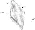
- Fig. 2 shows now the inventive equipment of the vacuum insulation panel 1.
- the vacuum insulation panel 1 on its first, in Fig. 2 rear outer surface 2 is provided over its entire surface with a mechanically dense protective layer 5.
- This protective layer 5 is designed so that it protects against mechanical attack with sharp-edged tools such as a knife or a cutter in any case to a considerable extent.
- the first protective layer 5 is designed as a laminated, in particular glued, protective plastic.
- a plastic film is suitable according to the invention PVC (polyvinyl chloride).
- Materials with similar mechanical properties, which materials are not within the scope of the invention, are also the plastics PP, PE, PET, etc., but also materials such.
- Fig. 2 shows now further that the vacuum insulation panel 1 also on the opposite second outer surface 3, the in Fig. 2 is front, full surface is provided with a protective layer 6.
- the second protective layer 6 is designed as a non-mechanically dense, but better elastic cushioning protective layer 6. It therefore has different properties than the first protective layer 5. Therefore, the vacuum insulation panel 1 according to the invention can be used universally.
- the second protective layer 6 is preferred and executed in the illustrated embodiment so that it consists of a temperature resistant to temperatures up to 120 ° C material.
- the second protective layer 6 is designed as a laminated, in particular glued, thick layer of foam plastic.
- Suitable foam plastics according to the invention are PE (polyethylene) or a cellular rubber, in particular EPDM (ethylene-propylene-diene rubber).
- a thickness of about 0.3 mm is recommended if it consists of PVC.
- a thickness of 3 mm is recommended if it consists of PE foam and it is recommended that a thickness of 2 mm, if it consists of EPDM.
- FIG. 2 illustrated embodiment also shows that here two opposite edges 4 of the vacuum insulation panel 1 are also covered by the first protective layer 5, so that even there the high barrier film is protected against mechanical loading with sharp-edged tools.
Landscapes
- Engineering & Computer Science (AREA)
- General Engineering & Computer Science (AREA)
- Mechanical Engineering (AREA)
- Thermal Insulation (AREA)
Description
- Die Erfindung betrifft ein Vakuumisolationspaneel mit den Merkmalen des Oberbegriffs von Anspruch 1.
- Vakuumisolationspaneele sind plattenförmige Wärmeisolationselemente, die in verschiedenen Ausführungsformen bekannt sind (siehe Wikipedia "Vakuumdämmplatte", Abruf vom 03.11.2014;
DE 10 2010 019 074 A1 ). In welcher Konstruktionsweise ein Vakuumisolationspaneel ausgebildet ist, ist für die vorliegende Erfindung grundsätzlich beliebig. Vorzugsweise sollte das Vakuumisolationspaneel jedoch so ausgebildet sein, dass es jedenfalls in begrenztem Maße biegbar ist. - Regelmäßig hat ein Vakuumisolationspaneel einen Grundkörper aus einem offenporigen Werkstoff, der dem Vakuumisolationspaneel die erforderliche mechanische Stabilität gibt. Seine Offenporigkeit gewährleistet eine ausreichende Evakuierbarkeit dieses Grundkörpers. Der Grundkörper ist mit einer möglichst vollständig gasdichten Folie, einer sog. "Hochbarrierefolie", gasdicht umschlossen. Der von der Folie gebildete, durch den Grundkörper ausgefüllte Innenraum ist evakuiert, wodurch die gewünschten Wärmeisolationseigenschaften erreicht werden.
- Typischerweise hat also ein plattenförmiges Vakuumisolationspaneel zwei einander gegenüberliegende Außenflächen. Diese sind über schmale umlaufende Ränder miteinander verbunden.
- Bei dem aus der Praxis bekannten Vakuumisolationspaneel, von dem die Erfindung ausgeht, ist das Vakuumisolationspaneel auf einer Außenfläche vollflächig mit einer mechanisch dichten Schutzschicht versehen, die die gegen mechanische Beschädigungen empfindliche Oberfläche des Vakuumisolationspaneels aus der besagten Hochbarrierefolie gegen mechanische Beaufschlagung selbst mit scharfkantigen Werkzeugen wie einem Messer oder einem Cutter schützt. Das aus der Praxis bekannte Beispiel eines Vakuumisolationspaneels hat auf der besagten Außenfläche eine Schutzfolie aus PVC aufgeklebt. Es gibt aber auch andere Schutzschichten, die eine ähnliche mechanische Schutzwirkung erfüllen. Beispielsweise kann man die Schutzschicht auch durch einen Schutzanstrich erreichen oder dadurch, dass man das Vakuumisolationspaneel auf dieser Außenfläche mit einer in einer Form angegossenen Schutzschicht, beispielsweise aus PU, versieht.
- Vakuumisolationspaneele der zuvor beschriebenen, auf einer Außenfläche oder zumindest auf dem größten Teil der Außenfläche mit einer in bestimmter Weise ausgestalteten Schutzschicht versehenen Art sind für einen ganz bestimmten Einsatzzweck einsetzbar. Für einen anderen Einsatzzweck muss man ein anderes Vakuumisolationspaneel wählen. Aus dem Dokument
WO 03/072684 A1 - Der Lehre der vorliegenden Erfindung liegt die Aufgabe zugrunde, das bekannte Vakuumisolationspaneel, das auf einer Außenfläche vollflächig mit einer mechanisch dichten Schutzschicht versehen ist, so auszugestalten und weiterzubilden, dass es universeller als bisher eingesetzt werden kann.
- Das zuvor aufgezeigte Problem ist bei einem Vakuumisolationspaneel mit den Merkmalen des Oberbegriffs von Anspruch 1 durch die Merkmale des kennzeichnenden Teils von Anspruch 1 gelöst.
- Erfindungsgemäß ist vorgesehen, dass das Vakuumisolationspaneel auch auf der gegenüberliegenden, zweiten Außenfläche vollflächig oder zumindest auf dem größten Teil mit einer Schutzschicht versehen ist und dass die zweite Schutzschicht als nicht mechanisch dichte, jedoch elastisch polsternde Schutzschicht ausgeführt ist.
- Das Vakuumisolationspaneel ist also auf der der ersten Außenfläche gegenüberliegenden zweiten Außenfläche mit einer anders ausgestalteten Schutzschicht versehen. Damit hat das Vakuumisolationspaneel mit Hilfe der an der zweiten Außenfläche vollflächig oder zumindest auf dem größten Teil vorgesehenen zweiten Schutzschicht die Voraussetzungen für einen anders gearteten Anwendungsfall. Hier geht es nicht um einen Schutz gegen mechanische Beaufschlagung mit scharfkantigen Werkzeugen, sondern an dieser zweiten Außenfläche ist die Schutzschicht so ausgestaltet, dass sie eine Polsterungsfunktion erfüllt. Die Schutzschicht ist also relativ dick und hat aufgrund der Wahl von Material und Ausgestaltung eine erhebliche Elastizität. Damit ist diese Schutzschicht beispielsweise besonders geeignet, Unebenheiten in einer Oberfläche, an die das Vakuumisolationspaneel angepresst wird, auszugleichen. Beispielsweise wird das Vakuumisolationspaneel mit Hilfe dieser elastisch polsternden Schutzschicht vor scharfkantigen Schweißpickeln, die sich auf der Außenseite eines im Schweißverfahren aus mehreren Teilen hergestellten Behälters unvermeidbar finden, geschützt.
- Besonders bevorzugt ist es, wenn die zweite Schutzschicht aus einem für Temperaturen bis zu 120°C widerstandsfähigen Material besteht. Damit kann man beispielsweise ein Vakuumisolationspaneel gemäß der Erfindung an einem Warmwasserspeicher anbringen.
- Für die Auswahl des Werkstoffes für die zweite Schutzschicht wird nach der Erfindung empfohlen, dass die zweite Schutzschicht als aufkaschierte, insbesondere aufgeklebte, dicke Schicht aus PE-Schaum oder aus einem Zellkautschuk ausgeführt ist. Zellkautschuk ist in verschiedenen Ausführungsformen bekannt. Besonders zweckmäßig ist ein EPDM (Ethylen-Propylen-DienKautschuk). Hat man eine Schutzschicht aus PE-Schaum, so wird man mit einer Dicke von 2 mm bis 5 mm, vorzugsweise von ca. 3 mm arbeiten. Bei EPDM hingegen wird man mit etwas geringerer Dicke auskommen, wenn man eine vergleichbare elastische Federwirkung erreichen will, hier reicht eine Dicke von etwa 1 mm bis 3 mm, vorzugsweise von ca. 2 mm.
- Für die erste Schutzschicht, die aus PVC ausgeführt ist, empfiehlt sich nach der Erfindung eine Dicke von 0,2 mm bis 1,0 mm, vorzugsweise von ca. 0,3 mm.
Das erfindungsgemäße Vakuumisolationspaneel ist also im Ergebnis auf beiden einander gegenüberliegenden Außenflächen mit jeweils einer Schutzschicht geschützt, die dort jeweils aufkaschiert ist. Die beiden Schutzschichten haben aber gezielt unterschiedliche Eigenschaften, um das Vakuumisolationspaneel universell einsetzen zu können. - Auch die Ränder des Vakuumisolationspaneels haben natürlich die gegen Beschädigungen empfindliche Hochbarrierefolie. Die ohnehin vorhandenen Schutzschichten kann man demzufolge auch zum Schutz der Ränder nutzen, indem man mindestens eine Schutzschicht bis auf mindestens zwei einander gegenüberliegenden Ränder des Vakuumisolationspaneels herumzieht.
- Besonders bevorzugt ist das Vakuumisolationspaneel insgesamt biegbar. Vorzugsweise kann es auch bereits von vornherein kreisbogenförmig gebogen mit einem an den späteren Einsatzzweck angepassten Biegeradius ausgeführt sein.
- Im Folgenden wird die Erfindung anhand einer lediglich ein Ausführungsbeispiel darstellenden Zeichnung näher erläutert. In der Zeichnung zeigt
- Fig. 1
- in einer perspektivischen Darstellung ein Vakuumisolationspaneel für sich und
- Fig. 2
- in einer
Fig. 1 entsprechenden Darstellung das Vakuumisolationspaneel ausFig. 1 , nunmehr auf beiden einander gegenüberliegenden Außenflächen mit jeweils einer Schutzschicht kaschiert. -
Fig. 1 zeigt das Vakuumisolationspaneel 1, von dem die Erfindung ausgeht. Es sollte vorzugsweise jedenfalls mit begrenztem Radius biegbar sein. Dieses Vakuumisolationspaneel 1 hat zwei einander gegenüberliegende Außenflächen 2, 3 und diese Außenflächen 2, 3 verbindende Ränder 4. All das ergibt sich ausFig. 1 . -
Fig. 2 zeigt nun die erfindungsgemäße Ausstattung des Vakuumisolationspaneels 1. Zunächst ist vorgesehen, dass das Vakuumisolationspaneel 1 auf seiner ersten, inFig. 2 rückwärtigen Außenfläche 2 vollflächig mit einer mechanisch dichten Schutzschicht 5 versehen ist. Diese Schutzschicht 5 ist so ausgestaltet, dass sie gegen mechanische Beaufschlagung mit scharfkantigen Werkzeugen wie beispielsweise einem Messer oder einem Cutter jedenfalls in erheblichem Maße schützt. - Nach der Erfindung ist vorgesehen, dass die erste Schutzschicht 5 als aufkaschierte, insbesondere aufgeklebte, Schutzfolie aus Kunststoff ausgeführt ist. Für eine solche Kunststofffolie eignet sich nach der Erfindung PVC (Polyvinylchlorid). Werkstoffe mit ähnlichen mechanisch relevanten Eigenschaften, welche Werkstoffe jedoch nicht im Rahmen der Erfindung liegen, sind auch die Kunststoffe PP, PE, PET, uvm., aber auch Materialien wie z.B. Karton, die hier ebenfalls Verwendung finden können, ggf. in Kombination mit einem Kunststoff.
-
Fig. 2 zeigt nun ferner, dass das Vakuumisolationspaneel 1 auch auf der gegenüberliegenden zweiten Außenfläche 3, die inFig. 2 vorne liegt, vollflächig mit einer Schutzschicht 6 versehen ist. Die zweite Schutzschicht 6 ist als nicht mechanisch dichte, jedoch umso besser elastisch polsternde Schutzschicht 6 ausgeführt. Sie hat deswegen andere Eigenschaften als die erste Schutzschicht 5. Deshalb lässt sich das Vakuumisolationspaneel 1 gemäß der Erfindung universell einsetzen. - Die zweite Schutzschicht 6 ist bevorzugt und im dargestellten Ausführungsbeispiel so ausgeführt, dass sie aus einem für Temperaturen bis zu 120°C widerstandsfähigen Material besteht.
- Nach der Erfindung empfiehlt es sich, dass die zweite Schutzschicht 6 als aufkaschierte, insbesondere aufgeklebte, dicke Schicht aus Schaumkunststoff ausgeführt ist. Als Schaumkunststoff kommen nach der Erfindung PE (Polyethylen) oder ein Zellkautschuk, insbesondere EPDM (Ethylen-Propylen-Dien-Kautschuk) in Frage.
- Für die erste Schutzschicht 5 empfiehlt sich eine Dicke von etwa 0,3 mm, wenn sie aus PVC besteht.
- Für die zweite Schutzschicht 6 empfiehlt sich eine Dicke von 3 mm, wenn sie aus PE-Schaum besteht und es empfiehlt sich eine Dicke von 2 mm, wenn sie aus EPDM besteht.
- Das in
Fig. 2 dargestellte Ausführungsbeispiel zeigt ferner, dass hier zwei einander gegenüberliegende Ränder 4 des Vakuumisolationspaneels 1 ebenfalls durch die erste Schutzschicht 5 abgedeckt sind, so dass auch dort die Hochbarrierefolie gegen mechanische Beaufschlagung mit scharfkantigen Werkzeugen geschützt ist. -
- 1
- Vakuumisolationspaneel
- 2
- erste Außenfläche
- 3
- zweite Außenfläche
- 4
- Rand
- 5
- erste Schutzschicht
- 6
- zweite Schutzschicht
Claims (6)
- Vakuumisolationspaneel,
mit zwei einander gegenüberliegenden Außenflächen (2; 3) und diese Außenflächen (2; 3) verbindenden Rändern (4),
wobei das Vakuumisolationspaneel (1) auf einer Außenfläche (2) vollflächig oder zumindest auf dem größten Teil mit einer mechanisch dichten ersten Schutzschicht (5) versehen ist, die gegen mechanische Beaufschlagung mit scharfkantigen Werkzeugen wie beispielsweise einem Messer oder einem Cutter schützt,
dadurch gekennzeichnet,
dass die erste Schutzschicht (5) als aufkaschierte Schutzfolie aus PVC mit einer Dicke von 0,2 mm bis 1,0 mm ausgeführt ist,
dass das Vakuumisolationspaneel (1) auch auf der gegenüberliegenden zweiten Außenfläche (3) vollflächig oder zumindest auf dem größten Teil mit einer Schutzschicht (6) versehen ist, welche als nicht mechanisch dichte, jedoch elastisch polsternde zweite Schutzschicht (6) ausgeführt ist, dass die zweite Schutzschicht (6) als aufkaschierte Schicht aus PE-Schaum mit einer Dicke von 2 mm bis 5 mm oder aus einem Zellkautschuk, insbesondere aus EPDM, mit einer Dicke von 1 mm bis 3 mm ausgeführt ist. - Vakuumisolationspaneel nach Anspruch 1, dadurch gekennzeichnet,
dass die erste Schutzschicht (5) und/oder die zweite Schutzschicht (5) aufgeklebt sind. - Vakuumisolationspaneel nach Anspruch 1 oder 2, dadurch gekennzeichnet, dass die erste Schutzschicht (5) eine Dicke von 0,3 mm aufweist.
- Vakuumisolationspaneel nach einem der Ansprüche 1 bis 3, dadurch gekennzeichnet,
dass die zweite Schutzschicht (6) bei Ausführung aus PE-Schaum eine Dicke von 3 mm und bei Ausführung aus einem Zellkautschuk, insbesondere aus EPDM, eine Dicke von 2 mm aufweist. - Vakuumisolationspaneel nach einem der Ansprüche 1 bis 4, dadurch gekennzeichnet,
dass mindestens zwei einander gegenüberliegende Ränder (4) des Vakuumisolationspaneels (1) ebenfalls durch eine der beiden Schutzschichten (5; 6) abgedeckt sind. - Vakuumisolationspaneel nach einem der Ansprüche 1 bis 5, dadurch gekennzeichnet,
dass das Vakuumisolationspaneel insgesamt biegbar und vorzugsweise kreisbogenförmig gebogen ausgeführt ist.
Applications Claiming Priority (1)
| Application Number | Priority Date | Filing Date | Title |
|---|---|---|---|
| DE202014008767.9U DE202014008767U1 (de) | 2014-11-06 | 2014-11-06 | Vakuumisolationspaneel |
Publications (2)
| Publication Number | Publication Date |
|---|---|
| EP3018398A1 EP3018398A1 (de) | 2016-05-11 |
| EP3018398B1 true EP3018398B1 (de) | 2019-11-20 |
Family
ID=52430606
Family Applications (1)
| Application Number | Title | Priority Date | Filing Date |
|---|---|---|---|
| EP15002967.6A Active EP3018398B1 (de) | 2014-11-06 | 2015-10-19 | Vakuumisolationspaneel |
Country Status (2)
| Country | Link |
|---|---|
| EP (1) | EP3018398B1 (de) |
| DE (1) | DE202014008767U1 (de) |
Families Citing this family (8)
| Publication number | Priority date | Publication date | Assignee | Title |
|---|---|---|---|---|
| US10603865B2 (en) * | 2014-12-25 | 2020-03-31 | AGC Inc. | Insulating member and its attaching method |
| WO2017091761A1 (en) | 2015-11-25 | 2017-06-01 | Yeti Coolers, Llc | Insulating container having vacuum insulated panels and method |
| USD821824S1 (en) | 2017-05-16 | 2018-07-03 | Yeti Coolers, Llc | Insulating device |
| DE202017004137U1 (de) | 2017-08-07 | 2018-11-12 | Va-Q-Tec Ag | Vakuumisolationspaneel-Anordnung |
| DE102017007365A1 (de) | 2017-08-07 | 2019-02-07 | Va-Q-Tec Ag | Vakuumisolationspaneel-Anordnung |
| DE102018109629B4 (de) | 2018-04-23 | 2023-05-17 | Va-Q-Tec Ag | Verfahren zur Überprüfung der Funktionstüchtigkeit eines Vakuumisolationspaneels |
| DE202018102967U1 (de) | 2018-05-28 | 2018-06-11 | Va-Q-Tec Ag | Transportbehältersystem zum Transport eines temperatursensiblen Gegenstands in einem Sollbereich einer Behälterinnentemperatur |
| DE102018124162A1 (de) | 2018-05-28 | 2019-11-28 | Va-Q-Tec Ag | Verfahren zum Bereitstellen eines Transportbehältersystems mit einem Sollbereich der Transportbehälterinnentemperatur sowie ein Transportbehältersystem |
Family Cites Families (5)
| Publication number | Priority date | Publication date | Assignee | Title |
|---|---|---|---|---|
| DE10123453A1 (de) * | 2001-05-14 | 2002-11-21 | Va Q Tec Ag | Vakuumdämmplattensystem mit mehrfacher Umhüllung |
| US6858280B2 (en) * | 2002-02-26 | 2005-02-22 | Technology Applications, Inc. | Microsphere insulation systems |
| DE202004015843U1 (de) * | 2004-10-13 | 2005-03-24 | Va Q Tec Ag | Folienumhüllte Vakuumdämmung |
| DE102009054432A1 (de) * | 2009-11-25 | 2011-05-26 | Ewald Dörken Ag | Wärmedämmsystem für eine Gebäudehülle |
| DE102010019074A1 (de) | 2010-04-30 | 2011-11-03 | Va-Q-Tec Ag | Evakuiertes Flächengebilde zur Wärmedämmung |
-
2014
- 2014-11-06 DE DE202014008767.9U patent/DE202014008767U1/de not_active Expired - Lifetime
-
2015
- 2015-10-19 EP EP15002967.6A patent/EP3018398B1/de active Active
Non-Patent Citations (1)
| Title |
|---|
| None * |
Also Published As
| Publication number | Publication date |
|---|---|
| DE202014008767U1 (de) | 2015-01-09 |
| EP3018398A1 (de) | 2016-05-11 |
Similar Documents
| Publication | Publication Date | Title |
|---|---|---|
| EP3018398A1 (de) | Vakuumisolationspaneel | |
| DE102013022086A1 (de) | Kantenleiste | |
| EP3060419B1 (de) | Zweiteiliges bauteil | |
| EP3077277A1 (de) | Kofferaufbau für ein nutzfahrzeug | |
| DE102016203497A1 (de) | Heizeinrichtung für einen Kfz-Betriebsflüssigkeitstank mit einem PTC-Kunststoffkörper | |
| EP3665004A1 (de) | Vakuumisolationspaneel-anordnung | |
| DE202017107801U1 (de) | Thermisch gedämmtes Rohr | |
| DE102011085175B4 (de) | Haushaltsgerät, insbesondere Haushaltsgeschirrspülmaschine, mit Butylmaterial, insbesondere Butylkleber auf einer Bauteilwand | |
| DE102014108549A1 (de) | Brandgeschützte Kabel-/Rohrdurchführung | |
| DE102008046878B3 (de) | Verbundwerkstoff und Verfahren zur Herstellung eines Verbundwerkstoff | |
| BE1021751B1 (de) | Installationsdose fur elektrotechnische anwendungen | |
| DE2057421C2 (de) | Verpackung aus einem äußeren Zuschnitt aus Karton sowie einem darin tiefgezogenen Futter | |
| CH706106A2 (de) | Installationsdose für elektronische Anwendungen. | |
| DE102013005867A1 (de) | Transportbehälter für den Transport hochwertiger Inhalte | |
| DE202008009248U1 (de) | Wärmedämmendes, plattenförmiges Bauelement für Wand- oder Fußbodenheizungssysteme | |
| DE60306608T2 (de) | Laminat | |
| EP1834762A2 (de) | Mehrschichtige Baufolie | |
| DE102019134948B3 (de) | Lebensmittelschale | |
| EP3141673A1 (de) | Gekantetes blech | |
| DE102010028576B4 (de) | Strahlenschutzformkörper und dessen Verwendung | |
| DE102016201484A1 (de) | Beschusshemmendes Bauteil zum Bau eines Schutzraumes | |
| DE20219215U1 (de) | Abdichtbahnmaterial | |
| DE202012101648U1 (de) | Schalldämpfende Folie | |
| EP3441660B1 (de) | Anschlussvorrichtung | |
| DE102017108968A1 (de) | Gebäudeabschlusselement |
Legal Events
| Date | Code | Title | Description |
|---|---|---|---|
| PUAI | Public reference made under article 153(3) epc to a published international application that has entered the european phase |
Free format text: ORIGINAL CODE: 0009012 |
|
| AK | Designated contracting states |
Kind code of ref document: A1 Designated state(s): AL AT BE BG CH CY CZ DE DK EE ES FI FR GB GR HR HU IE IS IT LI LT LU LV MC MK MT NL NO PL PT RO RS SE SI SK SM TR |
|
| AX | Request for extension of the european patent |
Extension state: BA ME |
|
| STAA | Information on the status of an ep patent application or granted ep patent |
Free format text: STATUS: REQUEST FOR EXAMINATION WAS MADE |
|
| 17P | Request for examination filed |
Effective date: 20161027 |
|
| RBV | Designated contracting states (corrected) |
Designated state(s): AL AT BE BG CH CY CZ DE DK EE ES FI FR GB GR HR HU IE IS IT LI LT LU LV MC MK MT NL NO PL PT RO RS SE SI SK SM TR |
|
| GRAP | Despatch of communication of intention to grant a patent |
Free format text: ORIGINAL CODE: EPIDOSNIGR1 |
|
| STAA | Information on the status of an ep patent application or granted ep patent |
Free format text: STATUS: GRANT OF PATENT IS INTENDED |
|
| INTG | Intention to grant announced |
Effective date: 20190624 |
|
| GRAS | Grant fee paid |
Free format text: ORIGINAL CODE: EPIDOSNIGR3 |
|
| GRAA | (expected) grant |
Free format text: ORIGINAL CODE: 0009210 |
|
| STAA | Information on the status of an ep patent application or granted ep patent |
Free format text: STATUS: THE PATENT HAS BEEN GRANTED |
|
| RAP1 | Party data changed (applicant data changed or rights of an application transferred) |
Owner name: VA-Q-TEC AG |
|
| AK | Designated contracting states |
Kind code of ref document: B1 Designated state(s): AL AT BE BG CH CY CZ DE DK EE ES FI FR GB GR HR HU IE IS IT LI LT LU LV MC MK MT NL NO PL PT RO RS SE SI SK SM TR |
|
| REG | Reference to a national code |
Ref country code: GB Ref legal event code: FG4D Free format text: NOT ENGLISH |
|
| REG | Reference to a national code |
Ref country code: CH Ref legal event code: EP |
|
| REG | Reference to a national code |
Ref country code: DE Ref legal event code: R096 Ref document number: 502015010960 Country of ref document: DE |
|
| REG | Reference to a national code |
Ref country code: IE Ref legal event code: FG4D Free format text: LANGUAGE OF EP DOCUMENT: GERMAN |
|
| REG | Reference to a national code |
Ref country code: AT Ref legal event code: REF Ref document number: 1204585 Country of ref document: AT Kind code of ref document: T Effective date: 20191215 |
|
| REG | Reference to a national code |
Ref country code: NL Ref legal event code: MP Effective date: 20191120 |
|
| REG | Reference to a national code |
Ref country code: LT Ref legal event code: MG4D |
|
| PG25 | Lapsed in a contracting state [announced via postgrant information from national office to epo] |
Ref country code: FI Free format text: LAPSE BECAUSE OF FAILURE TO SUBMIT A TRANSLATION OF THE DESCRIPTION OR TO PAY THE FEE WITHIN THE PRESCRIBED TIME-LIMIT Effective date: 20191120 Ref country code: LV Free format text: LAPSE BECAUSE OF FAILURE TO SUBMIT A TRANSLATION OF THE DESCRIPTION OR TO PAY THE FEE WITHIN THE PRESCRIBED TIME-LIMIT Effective date: 20191120 Ref country code: SE Free format text: LAPSE BECAUSE OF FAILURE TO SUBMIT A TRANSLATION OF THE DESCRIPTION OR TO PAY THE FEE WITHIN THE PRESCRIBED TIME-LIMIT Effective date: 20191120 Ref country code: NL Free format text: LAPSE BECAUSE OF FAILURE TO SUBMIT A TRANSLATION OF THE DESCRIPTION OR TO PAY THE FEE WITHIN THE PRESCRIBED TIME-LIMIT Effective date: 20191120 Ref country code: LT Free format text: LAPSE BECAUSE OF FAILURE TO SUBMIT A TRANSLATION OF THE DESCRIPTION OR TO PAY THE FEE WITHIN THE PRESCRIBED TIME-LIMIT Effective date: 20191120 Ref country code: BG Free format text: LAPSE BECAUSE OF FAILURE TO SUBMIT A TRANSLATION OF THE DESCRIPTION OR TO PAY THE FEE WITHIN THE PRESCRIBED TIME-LIMIT Effective date: 20200220 Ref country code: NO Free format text: LAPSE BECAUSE OF FAILURE TO SUBMIT A TRANSLATION OF THE DESCRIPTION OR TO PAY THE FEE WITHIN THE PRESCRIBED TIME-LIMIT Effective date: 20200220 Ref country code: GR Free format text: LAPSE BECAUSE OF FAILURE TO SUBMIT A TRANSLATION OF THE DESCRIPTION OR TO PAY THE FEE WITHIN THE PRESCRIBED TIME-LIMIT Effective date: 20200221 |
|
| PG25 | Lapsed in a contracting state [announced via postgrant information from national office to epo] |
Ref country code: HR Free format text: LAPSE BECAUSE OF FAILURE TO SUBMIT A TRANSLATION OF THE DESCRIPTION OR TO PAY THE FEE WITHIN THE PRESCRIBED TIME-LIMIT Effective date: 20191120 Ref country code: RS Free format text: LAPSE BECAUSE OF FAILURE TO SUBMIT A TRANSLATION OF THE DESCRIPTION OR TO PAY THE FEE WITHIN THE PRESCRIBED TIME-LIMIT Effective date: 20191120 Ref country code: IS Free format text: LAPSE BECAUSE OF FAILURE TO SUBMIT A TRANSLATION OF THE DESCRIPTION OR TO PAY THE FEE WITHIN THE PRESCRIBED TIME-LIMIT Effective date: 20200320 |
|
| PG25 | Lapsed in a contracting state [announced via postgrant information from national office to epo] |
Ref country code: AL Free format text: LAPSE BECAUSE OF FAILURE TO SUBMIT A TRANSLATION OF THE DESCRIPTION OR TO PAY THE FEE WITHIN THE PRESCRIBED TIME-LIMIT Effective date: 20191120 |
|
| PG25 | Lapsed in a contracting state [announced via postgrant information from national office to epo] |
Ref country code: PT Free format text: LAPSE BECAUSE OF FAILURE TO SUBMIT A TRANSLATION OF THE DESCRIPTION OR TO PAY THE FEE WITHIN THE PRESCRIBED TIME-LIMIT Effective date: 20200412 Ref country code: EE Free format text: LAPSE BECAUSE OF FAILURE TO SUBMIT A TRANSLATION OF THE DESCRIPTION OR TO PAY THE FEE WITHIN THE PRESCRIBED TIME-LIMIT Effective date: 20191120 Ref country code: RO Free format text: LAPSE BECAUSE OF FAILURE TO SUBMIT A TRANSLATION OF THE DESCRIPTION OR TO PAY THE FEE WITHIN THE PRESCRIBED TIME-LIMIT Effective date: 20191120 Ref country code: DK Free format text: LAPSE BECAUSE OF FAILURE TO SUBMIT A TRANSLATION OF THE DESCRIPTION OR TO PAY THE FEE WITHIN THE PRESCRIBED TIME-LIMIT Effective date: 20191120 Ref country code: CZ Free format text: LAPSE BECAUSE OF FAILURE TO SUBMIT A TRANSLATION OF THE DESCRIPTION OR TO PAY THE FEE WITHIN THE PRESCRIBED TIME-LIMIT Effective date: 20191120 Ref country code: ES Free format text: LAPSE BECAUSE OF FAILURE TO SUBMIT A TRANSLATION OF THE DESCRIPTION OR TO PAY THE FEE WITHIN THE PRESCRIBED TIME-LIMIT Effective date: 20191120 |
|
| REG | Reference to a national code |
Ref country code: DE Ref legal event code: R097 Ref document number: 502015010960 Country of ref document: DE |
|
| PG25 | Lapsed in a contracting state [announced via postgrant information from national office to epo] |
Ref country code: SM Free format text: LAPSE BECAUSE OF FAILURE TO SUBMIT A TRANSLATION OF THE DESCRIPTION OR TO PAY THE FEE WITHIN THE PRESCRIBED TIME-LIMIT Effective date: 20191120 Ref country code: SK Free format text: LAPSE BECAUSE OF FAILURE TO SUBMIT A TRANSLATION OF THE DESCRIPTION OR TO PAY THE FEE WITHIN THE PRESCRIBED TIME-LIMIT Effective date: 20191120 |
|
| PLBE | No opposition filed within time limit |
Free format text: ORIGINAL CODE: 0009261 |
|
| STAA | Information on the status of an ep patent application or granted ep patent |
Free format text: STATUS: NO OPPOSITION FILED WITHIN TIME LIMIT |
|
| 26N | No opposition filed |
Effective date: 20200821 |
|
| PG25 | Lapsed in a contracting state [announced via postgrant information from national office to epo] |
Ref country code: SI Free format text: LAPSE BECAUSE OF FAILURE TO SUBMIT A TRANSLATION OF THE DESCRIPTION OR TO PAY THE FEE WITHIN THE PRESCRIBED TIME-LIMIT Effective date: 20191120 Ref country code: PL Free format text: LAPSE BECAUSE OF FAILURE TO SUBMIT A TRANSLATION OF THE DESCRIPTION OR TO PAY THE FEE WITHIN THE PRESCRIBED TIME-LIMIT Effective date: 20191120 |
|
| PG25 | Lapsed in a contracting state [announced via postgrant information from national office to epo] |
Ref country code: IT Free format text: LAPSE BECAUSE OF FAILURE TO SUBMIT A TRANSLATION OF THE DESCRIPTION OR TO PAY THE FEE WITHIN THE PRESCRIBED TIME-LIMIT Effective date: 20191120 |
|
| REG | Reference to a national code |
Ref country code: CH Ref legal event code: PL |
|
| PG25 | Lapsed in a contracting state [announced via postgrant information from national office to epo] |
Ref country code: MC Free format text: LAPSE BECAUSE OF FAILURE TO SUBMIT A TRANSLATION OF THE DESCRIPTION OR TO PAY THE FEE WITHIN THE PRESCRIBED TIME-LIMIT Effective date: 20191120 Ref country code: LU Free format text: LAPSE BECAUSE OF NON-PAYMENT OF DUE FEES Effective date: 20201019 |
|
| REG | Reference to a national code |
Ref country code: BE Ref legal event code: MM Effective date: 20201031 |
|
| PG25 | Lapsed in a contracting state [announced via postgrant information from national office to epo] |
Ref country code: LI Free format text: LAPSE BECAUSE OF NON-PAYMENT OF DUE FEES Effective date: 20201031 Ref country code: BE Free format text: LAPSE BECAUSE OF NON-PAYMENT OF DUE FEES Effective date: 20201031 Ref country code: CH Free format text: LAPSE BECAUSE OF NON-PAYMENT OF DUE FEES Effective date: 20201031 |
|
| PG25 | Lapsed in a contracting state [announced via postgrant information from national office to epo] |
Ref country code: IE Free format text: LAPSE BECAUSE OF NON-PAYMENT OF DUE FEES Effective date: 20201019 |
|
| REG | Reference to a national code |
Ref country code: AT Ref legal event code: MM01 Ref document number: 1204585 Country of ref document: AT Kind code of ref document: T Effective date: 20201019 |
|
| PG25 | Lapsed in a contracting state [announced via postgrant information from national office to epo] |
Ref country code: AT Free format text: LAPSE BECAUSE OF NON-PAYMENT OF DUE FEES Effective date: 20201019 |
|
| PGFP | Annual fee paid to national office [announced via postgrant information from national office to epo] |
Ref country code: DE Payment date: 20211020 Year of fee payment: 7 Ref country code: GB Payment date: 20211022 Year of fee payment: 7 |
|
| PGFP | Annual fee paid to national office [announced via postgrant information from national office to epo] |
Ref country code: FR Payment date: 20211022 Year of fee payment: 7 |
|
| PG25 | Lapsed in a contracting state [announced via postgrant information from national office to epo] |
Ref country code: TR Free format text: LAPSE BECAUSE OF FAILURE TO SUBMIT A TRANSLATION OF THE DESCRIPTION OR TO PAY THE FEE WITHIN THE PRESCRIBED TIME-LIMIT Effective date: 20191120 Ref country code: MT Free format text: LAPSE BECAUSE OF FAILURE TO SUBMIT A TRANSLATION OF THE DESCRIPTION OR TO PAY THE FEE WITHIN THE PRESCRIBED TIME-LIMIT Effective date: 20191120 Ref country code: CY Free format text: LAPSE BECAUSE OF FAILURE TO SUBMIT A TRANSLATION OF THE DESCRIPTION OR TO PAY THE FEE WITHIN THE PRESCRIBED TIME-LIMIT Effective date: 20191120 |
|
| PG25 | Lapsed in a contracting state [announced via postgrant information from national office to epo] |
Ref country code: MK Free format text: LAPSE BECAUSE OF FAILURE TO SUBMIT A TRANSLATION OF THE DESCRIPTION OR TO PAY THE FEE WITHIN THE PRESCRIBED TIME-LIMIT Effective date: 20191120 |
|
| REG | Reference to a national code |
Ref country code: DE Ref legal event code: R119 Ref document number: 502015010960 Country of ref document: DE |
|
| GBPC | Gb: european patent ceased through non-payment of renewal fee |
Effective date: 20221019 |
|
| PG25 | Lapsed in a contracting state [announced via postgrant information from national office to epo] |
Ref country code: FR Free format text: LAPSE BECAUSE OF NON-PAYMENT OF DUE FEES Effective date: 20221031 Ref country code: DE Free format text: LAPSE BECAUSE OF NON-PAYMENT OF DUE FEES Effective date: 20230503 |
|
| PG25 | Lapsed in a contracting state [announced via postgrant information from national office to epo] |
Ref country code: GB Free format text: LAPSE BECAUSE OF NON-PAYMENT OF DUE FEES Effective date: 20221019 |