EP3017987A1 - Dispositif de traction hybride de véhicule automobile et mécanisme de transmission de puissance - Google Patents
Dispositif de traction hybride de véhicule automobile et mécanisme de transmission de puissance Download PDFInfo
- Publication number
- EP3017987A1 EP3017987A1 EP15185795.0A EP15185795A EP3017987A1 EP 3017987 A1 EP3017987 A1 EP 3017987A1 EP 15185795 A EP15185795 A EP 15185795A EP 3017987 A1 EP3017987 A1 EP 3017987A1
- Authority
- EP
- European Patent Office
- Prior art keywords
- gear
- transmission mechanism
- secondary shaft
- gearbox
- electric machine
- Prior art date
- Legal status (The legal status is an assumption and is not a legal conclusion. Google has not performed a legal analysis and makes no representation as to the accuracy of the status listed.)
- Granted
Links
Images


Classifications
-
- B—PERFORMING OPERATIONS; TRANSPORTING
- B60—VEHICLES IN GENERAL
- B60K—ARRANGEMENT OR MOUNTING OF PROPULSION UNITS OR OF TRANSMISSIONS IN VEHICLES; ARRANGEMENT OR MOUNTING OF PLURAL DIVERSE PRIME-MOVERS IN VEHICLES; AUXILIARY DRIVES FOR VEHICLES; INSTRUMENTATION OR DASHBOARDS FOR VEHICLES; ARRANGEMENTS IN CONNECTION WITH COOLING, AIR INTAKE, GAS EXHAUST OR FUEL SUPPLY OF PROPULSION UNITS IN VEHICLES
- B60K6/00—Arrangement or mounting of plural diverse prime-movers for mutual or common propulsion, e.g. hybrid propulsion systems comprising electric motors and internal combustion engines
- B60K6/20—Arrangement or mounting of plural diverse prime-movers for mutual or common propulsion, e.g. hybrid propulsion systems comprising electric motors and internal combustion engines the prime-movers consisting of electric motors and internal combustion engines, e.g. HEVs
- B60K6/42—Arrangement or mounting of plural diverse prime-movers for mutual or common propulsion, e.g. hybrid propulsion systems comprising electric motors and internal combustion engines the prime-movers consisting of electric motors and internal combustion engines, e.g. HEVs characterised by the architecture of the hybrid electric vehicle
- B60K6/48—Parallel type
-
- B—PERFORMING OPERATIONS; TRANSPORTING
- B60—VEHICLES IN GENERAL
- B60K—ARRANGEMENT OR MOUNTING OF PROPULSION UNITS OR OF TRANSMISSIONS IN VEHICLES; ARRANGEMENT OR MOUNTING OF PLURAL DIVERSE PRIME-MOVERS IN VEHICLES; AUXILIARY DRIVES FOR VEHICLES; INSTRUMENTATION OR DASHBOARDS FOR VEHICLES; ARRANGEMENTS IN CONNECTION WITH COOLING, AIR INTAKE, GAS EXHAUST OR FUEL SUPPLY OF PROPULSION UNITS IN VEHICLES
- B60K6/00—Arrangement or mounting of plural diverse prime-movers for mutual or common propulsion, e.g. hybrid propulsion systems comprising electric motors and internal combustion engines
- B60K6/20—Arrangement or mounting of plural diverse prime-movers for mutual or common propulsion, e.g. hybrid propulsion systems comprising electric motors and internal combustion engines the prime-movers consisting of electric motors and internal combustion engines, e.g. HEVs
- B60K6/22—Arrangement or mounting of plural diverse prime-movers for mutual or common propulsion, e.g. hybrid propulsion systems comprising electric motors and internal combustion engines the prime-movers consisting of electric motors and internal combustion engines, e.g. HEVs characterised by apparatus, components or means specially adapted for HEVs
- B60K6/36—Arrangement or mounting of plural diverse prime-movers for mutual or common propulsion, e.g. hybrid propulsion systems comprising electric motors and internal combustion engines the prime-movers consisting of electric motors and internal combustion engines, e.g. HEVs characterised by apparatus, components or means specially adapted for HEVs characterised by the transmission gearings
- B60K6/365—Arrangement or mounting of plural diverse prime-movers for mutual or common propulsion, e.g. hybrid propulsion systems comprising electric motors and internal combustion engines the prime-movers consisting of electric motors and internal combustion engines, e.g. HEVs characterised by apparatus, components or means specially adapted for HEVs characterised by the transmission gearings with the gears having orbital motion
-
- B—PERFORMING OPERATIONS; TRANSPORTING
- B60—VEHICLES IN GENERAL
- B60K—ARRANGEMENT OR MOUNTING OF PROPULSION UNITS OR OF TRANSMISSIONS IN VEHICLES; ARRANGEMENT OR MOUNTING OF PLURAL DIVERSE PRIME-MOVERS IN VEHICLES; AUXILIARY DRIVES FOR VEHICLES; INSTRUMENTATION OR DASHBOARDS FOR VEHICLES; ARRANGEMENTS IN CONNECTION WITH COOLING, AIR INTAKE, GAS EXHAUST OR FUEL SUPPLY OF PROPULSION UNITS IN VEHICLES
- B60K6/00—Arrangement or mounting of plural diverse prime-movers for mutual or common propulsion, e.g. hybrid propulsion systems comprising electric motors and internal combustion engines
- B60K6/20—Arrangement or mounting of plural diverse prime-movers for mutual or common propulsion, e.g. hybrid propulsion systems comprising electric motors and internal combustion engines the prime-movers consisting of electric motors and internal combustion engines, e.g. HEVs
- B60K6/50—Architecture of the driveline characterised by arrangement or kind of transmission units
- B60K6/54—Transmission for changing ratio
-
- B—PERFORMING OPERATIONS; TRANSPORTING
- B60—VEHICLES IN GENERAL
- B60K—ARRANGEMENT OR MOUNTING OF PROPULSION UNITS OR OF TRANSMISSIONS IN VEHICLES; ARRANGEMENT OR MOUNTING OF PLURAL DIVERSE PRIME-MOVERS IN VEHICLES; AUXILIARY DRIVES FOR VEHICLES; INSTRUMENTATION OR DASHBOARDS FOR VEHICLES; ARRANGEMENTS IN CONNECTION WITH COOLING, AIR INTAKE, GAS EXHAUST OR FUEL SUPPLY OF PROPULSION UNITS IN VEHICLES
- B60K6/00—Arrangement or mounting of plural diverse prime-movers for mutual or common propulsion, e.g. hybrid propulsion systems comprising electric motors and internal combustion engines
- B60K6/20—Arrangement or mounting of plural diverse prime-movers for mutual or common propulsion, e.g. hybrid propulsion systems comprising electric motors and internal combustion engines the prime-movers consisting of electric motors and internal combustion engines, e.g. HEVs
- B60K6/42—Arrangement or mounting of plural diverse prime-movers for mutual or common propulsion, e.g. hybrid propulsion systems comprising electric motors and internal combustion engines the prime-movers consisting of electric motors and internal combustion engines, e.g. HEVs characterised by the architecture of the hybrid electric vehicle
- B60K6/48—Parallel type
- B60K2006/4808—Electric machine connected or connectable to gearbox output shaft
-
- B—PERFORMING OPERATIONS; TRANSPORTING
- B60—VEHICLES IN GENERAL
- B60K—ARRANGEMENT OR MOUNTING OF PROPULSION UNITS OR OF TRANSMISSIONS IN VEHICLES; ARRANGEMENT OR MOUNTING OF PLURAL DIVERSE PRIME-MOVERS IN VEHICLES; AUXILIARY DRIVES FOR VEHICLES; INSTRUMENTATION OR DASHBOARDS FOR VEHICLES; ARRANGEMENTS IN CONNECTION WITH COOLING, AIR INTAKE, GAS EXHAUST OR FUEL SUPPLY OF PROPULSION UNITS IN VEHICLES
- B60K6/00—Arrangement or mounting of plural diverse prime-movers for mutual or common propulsion, e.g. hybrid propulsion systems comprising electric motors and internal combustion engines
- B60K6/20—Arrangement or mounting of plural diverse prime-movers for mutual or common propulsion, e.g. hybrid propulsion systems comprising electric motors and internal combustion engines the prime-movers consisting of electric motors and internal combustion engines, e.g. HEVs
- B60K6/42—Arrangement or mounting of plural diverse prime-movers for mutual or common propulsion, e.g. hybrid propulsion systems comprising electric motors and internal combustion engines the prime-movers consisting of electric motors and internal combustion engines, e.g. HEVs characterised by the architecture of the hybrid electric vehicle
- B60K6/48—Parallel type
- B60K2006/4816—Electric machine connected or connectable to gearbox internal shaft
-
- B—PERFORMING OPERATIONS; TRANSPORTING
- B60—VEHICLES IN GENERAL
- B60K—ARRANGEMENT OR MOUNTING OF PROPULSION UNITS OR OF TRANSMISSIONS IN VEHICLES; ARRANGEMENT OR MOUNTING OF PLURAL DIVERSE PRIME-MOVERS IN VEHICLES; AUXILIARY DRIVES FOR VEHICLES; INSTRUMENTATION OR DASHBOARDS FOR VEHICLES; ARRANGEMENTS IN CONNECTION WITH COOLING, AIR INTAKE, GAS EXHAUST OR FUEL SUPPLY OF PROPULSION UNITS IN VEHICLES
- B60K6/00—Arrangement or mounting of plural diverse prime-movers for mutual or common propulsion, e.g. hybrid propulsion systems comprising electric motors and internal combustion engines
- B60K6/20—Arrangement or mounting of plural diverse prime-movers for mutual or common propulsion, e.g. hybrid propulsion systems comprising electric motors and internal combustion engines the prime-movers consisting of electric motors and internal combustion engines, e.g. HEVs
- B60K6/42—Arrangement or mounting of plural diverse prime-movers for mutual or common propulsion, e.g. hybrid propulsion systems comprising electric motors and internal combustion engines the prime-movers consisting of electric motors and internal combustion engines, e.g. HEVs characterised by the architecture of the hybrid electric vehicle
- B60K6/48—Parallel type
- B60K2006/4833—Step up or reduction gearing driving generator, e.g. to operate generator in most efficient speed range
- B60K2006/4841—Step up or reduction gearing driving generator, e.g. to operate generator in most efficient speed range the gear provides shifting between multiple ratios
-
- F—MECHANICAL ENGINEERING; LIGHTING; HEATING; WEAPONS; BLASTING
- F16—ENGINEERING ELEMENTS AND UNITS; GENERAL MEASURES FOR PRODUCING AND MAINTAINING EFFECTIVE FUNCTIONING OF MACHINES OR INSTALLATIONS; THERMAL INSULATION IN GENERAL
- F16H—GEARING
- F16H2200/00—Transmissions for multiple ratios
- F16H2200/003—Transmissions for multiple ratios characterised by the number of forward speeds
- F16H2200/0034—Transmissions for multiple ratios characterised by the number of forward speeds the gear ratios comprising two forward speeds
-
- F—MECHANICAL ENGINEERING; LIGHTING; HEATING; WEAPONS; BLASTING
- F16—ENGINEERING ELEMENTS AND UNITS; GENERAL MEASURES FOR PRODUCING AND MAINTAINING EFFECTIVE FUNCTIONING OF MACHINES OR INSTALLATIONS; THERMAL INSULATION IN GENERAL
- F16H—GEARING
- F16H2200/00—Transmissions for multiple ratios
- F16H2200/20—Transmissions using gears with orbital motion
- F16H2200/2002—Transmissions using gears with orbital motion characterised by the number of sets of orbital gears
- F16H2200/2005—Transmissions using gears with orbital motion characterised by the number of sets of orbital gears with one sets of orbital gears
-
- F—MECHANICAL ENGINEERING; LIGHTING; HEATING; WEAPONS; BLASTING
- F16—ENGINEERING ELEMENTS AND UNITS; GENERAL MEASURES FOR PRODUCING AND MAINTAINING EFFECTIVE FUNCTIONING OF MACHINES OR INSTALLATIONS; THERMAL INSULATION IN GENERAL
- F16H—GEARING
- F16H2200/00—Transmissions for multiple ratios
- F16H2200/20—Transmissions using gears with orbital motion
- F16H2200/203—Transmissions using gears with orbital motion characterised by the engaging friction means not of the freewheel type, e.g. friction clutches or brakes
- F16H2200/2035—Transmissions using gears with orbital motion characterised by the engaging friction means not of the freewheel type, e.g. friction clutches or brakes with two engaging means
-
- F—MECHANICAL ENGINEERING; LIGHTING; HEATING; WEAPONS; BLASTING
- F16—ENGINEERING ELEMENTS AND UNITS; GENERAL MEASURES FOR PRODUCING AND MAINTAINING EFFECTIVE FUNCTIONING OF MACHINES OR INSTALLATIONS; THERMAL INSULATION IN GENERAL
- F16H—GEARING
- F16H2200/00—Transmissions for multiple ratios
- F16H2200/20—Transmissions using gears with orbital motion
- F16H2200/203—Transmissions using gears with orbital motion characterised by the engaging friction means not of the freewheel type, e.g. friction clutches or brakes
- F16H2200/2064—Transmissions using gears with orbital motion characterised by the engaging friction means not of the freewheel type, e.g. friction clutches or brakes using at least one positive clutch, e.g. dog clutch
-
- F—MECHANICAL ENGINEERING; LIGHTING; HEATING; WEAPONS; BLASTING
- F16—ENGINEERING ELEMENTS AND UNITS; GENERAL MEASURES FOR PRODUCING AND MAINTAINING EFFECTIVE FUNCTIONING OF MACHINES OR INSTALLATIONS; THERMAL INSULATION IN GENERAL
- F16H—GEARING
- F16H2200/00—Transmissions for multiple ratios
- F16H2200/20—Transmissions using gears with orbital motion
- F16H2200/2094—Transmissions using gears with orbital motion using positive clutches, e.g. dog clutches
-
- F—MECHANICAL ENGINEERING; LIGHTING; HEATING; WEAPONS; BLASTING
- F16—ENGINEERING ELEMENTS AND UNITS; GENERAL MEASURES FOR PRODUCING AND MAINTAINING EFFECTIVE FUNCTIONING OF MACHINES OR INSTALLATIONS; THERMAL INSULATION IN GENERAL
- F16H—GEARING
- F16H3/00—Toothed gearings for conveying rotary motion with variable gear ratio or for reversing rotary motion
- F16H3/44—Toothed gearings for conveying rotary motion with variable gear ratio or for reversing rotary motion using gears having orbital motion
- F16H3/46—Gearings having only two central gears, connected by orbital gears
- F16H3/48—Gearings having only two central gears, connected by orbital gears with single orbital gears or pairs of rigidly-connected orbital gears
- F16H3/52—Gearings having only two central gears, connected by orbital gears with single orbital gears or pairs of rigidly-connected orbital gears comprising orbital spur gears
- F16H3/54—Gearings having only two central gears, connected by orbital gears with single orbital gears or pairs of rigidly-connected orbital gears comprising orbital spur gears one of the central gears being internally toothed and the other externally toothed
-
- Y—GENERAL TAGGING OF NEW TECHNOLOGICAL DEVELOPMENTS; GENERAL TAGGING OF CROSS-SECTIONAL TECHNOLOGIES SPANNING OVER SEVERAL SECTIONS OF THE IPC; TECHNICAL SUBJECTS COVERED BY FORMER USPC CROSS-REFERENCE ART COLLECTIONS [XRACs] AND DIGESTS
- Y02—TECHNOLOGIES OR APPLICATIONS FOR MITIGATION OR ADAPTATION AGAINST CLIMATE CHANGE
- Y02T—CLIMATE CHANGE MITIGATION TECHNOLOGIES RELATED TO TRANSPORTATION
- Y02T10/00—Road transport of goods or passengers
- Y02T10/60—Other road transportation technologies with climate change mitigation effect
- Y02T10/62—Hybrid vehicles
Definitions
- the invention relates to a hybrid traction device for a motor vehicle comprising a heat engine with its manual or robotic gearbox, and an electric machine connected to the gearbox.
- a hybrid traction device for a motor vehicle having a gearbox with parallel shafts, a primary shaft transmits the power of a drive engine to a secondary shaft connected to the wheels of the vehicle, a an electric machine transmitting its power to the secondary shaft of the gearbox, and a two-speed decelerable power transmission mechanism between an electric machine and a gearbox shaft.
- the electric machine In hybrid vehicles, comprising a dual engine, thermal and electrical, the electric machine is sometimes linked to the engine on its so-called “accessories" side, such as the alternator. But, in order to increase the installed electric power, the efficiency of battery storage and retrieval energy exchanges, and to open these vehicles to new possibilities, in particular electric running, it seems preferable to connect the electrical machine. to the gearbox.
- hybrid powertrains whose electric machine is connected to one or the other of the shafts of the gearbox.
- the publication FR 2,772,675 describes in particular a powertrain comprising a heat engine, a gearbox, and an electric machine.
- the electric machine can be connected to one or the other shaft of the gearbox, according to several embodiments.
- the connection between the electric machine and the shaft of the box is a single fixed ratio, and this connection comprises a interconnection device.
- the connection is by pinion or chain.
- the interconnection device is arranged on the axis of the electric machine or on the axis of the shaft of the box. Depending on the connection between the electric machine and the box, the possibilities offered are different.
- the electric machine When linked to the primary shaft, the electric machine benefits from reduction ratios of the box, but it disrupts the inertia and the equivalent drag of the latter. In order for this disturbance to be supported by the synchronization devices, it is necessary to automate the gear changes. Thus, the supervisor controls the electric machine during gear changes, and limits or eliminates undesirable effects of inertia and drag. In some cases, the electric machine can achieve synchronization alone, and conventional synchronizers are removed. However, this architecture has the following disadvantage: as the electric machine is decoupled from the wheels during the shift, it can not ensure the continuity of complete acceleration, or partial, which would improve the performance of shifting a robotic gearbox.
- the electric machine when it is linked with the secondary shaft, the electric machine is able to restore energy permanently, including during shifts. But it does not benefit from the gear ratios of the gearbox. To increase the exchangeable power, it is then necessary to introduce a high gear ratio between the electric machine and the secondary shaft. Beyond a certain speed of the vehicle, this becomes a disadvantage, because the speed of machine rotation is excessive, and its performance becomes mediocre.
- the present invention proposes to arrange a two-speed power transmission mechanism between the electric machine and the secondary shaft of the gearbox.
- the electric machine can thus have a gear ratio short to be very effective during the slow movements of the vehicle, and a long ratio to remain operative over a reasonable speed range of the machine, during the rapid movements of the vehicle .
- the transmission mechanism is composed of two elements: the first is a speed reducer, and the second is a mechanical link with the secondary shaft of the box.
- the first element of the transmission device is an epicyclic gear train.
- the electric machine is permanently connected to the sun gear, and the ring gear is also permanently connected to the second element of the transmission device.
- the second element of the transmission device consists of a chain and of two gables.
- the first is connected to the crown of the planetary gear train, and the second to the secondary shaft.
- the planetary gear gives three states to the transmission device. Indeed, thanks to a sliding sleeve, the planet carrier can be connected to a gear wheel fixed on the housing of the device to give the short transmission ratio. It can be connected to the crown to give the long transmission ratio of one value. Finally, he can be free to disconnect the electric machine.
- the sliding sleeve of change of state is positioned by an electromechanical device consisting of a fork provided with two branches and a threaded protrusion constituting a nut, and a threaded shaft engaged in this nut, which is driven by an engine. electric controlled by a central management unit.
- the chain has a mechanical tensioning means consisting of two pads, supported by two arms articulated around a common axis.
- the arms and the pads are mutually repelled by a pre-loaded spring. If the electric machine is sometimes driving, sometimes generator, the strand of the chain and its relaxed arm are reversed depending on the mode of operation. With the proposed tensioning system, the inactive strand is always stretched by its pad which bears on the strand stretched through the spring.
- the entire device is supported by a plate, and contained in a housing which constitutes a sealed assembly having its own lubricant.
- Hybridization of the box consists in connecting to the latter an electric machine by a mechanical connection.
- This connection has two levels: the first is a two-speed gearbox by the use of an epicyclic gear and the second is a simple transmission chain.
- the hybrid traction device for a motor vehicle described in the figures comprises a gearbox with parallel shafts 200, a primary shaft 202 transmitting the power of a driving heat engine to a secondary shaft 203 connected to the wheels of the vehicle, and an electric machine 300 transmitting its power to the secondary shaft of the box 200.
- the power transmission mechanism 100 is a two-speed declutching mechanism 100, between the electric machine 300 and the gearbox shaft 203, which is mechanically connected to this shaft. It includes a enclosure consisting of a support plate mechanisms 101, and a closure housing 102. The entire mechanism is supported by the plate 101, and contained in the housing 102, which constitutes a sealed assembly having its own lubricant.
- a gear reducer consisting of a single epicyclic gear 110, provided with a sun gear 112 mounted on splines on a support sleeve 111, which is permanently coupled with the electric machine 300, for example by a splined connection.
- the sleeve 111 is supported by a ball bearing 114 centered in the housing 102. It is retained and held axially by a stop plate 116 which has a groove 116, a on its outer periphery.
- the sleeve 111 supports the sun gear 112 of the train. It is mounted on splines, and retained by the stop ring 113.
- a dynamic seal 118 of the transmission mechanism 100 to the electrical machine 300 is installed between the sleeve 111 and the housing 102.
- the sleeve 111 also supports the planet carrier 119. Without actually ensuring its centering, it limits its axial movement via the thrust pins 123, and offers an axial retention through the support ring 124 against the sun gear 112
- the satellite carrier 119 supports three satellites 120 guided on the needles 121, and held axially by the friction washers 122.
- the last element of the train is the ring 126, which is centered and driven in rotation by regular excrescences of the bell of the planetary gear 125.
- the bell 125 also supports a clutch 127 for locking the train, which is connected to the bell 125 in the same manner as the crown. The bell and the clutch are held axially by the stop ring 128.
- the electric machine 300 is permanently connected to the sun gear 112 of the epicyclic gear train, the crown 126 is mechanically connected to the secondary shaft 203 of the box.
- the second part of the transmission mechanism is composed mainly of a chain 154, installed between an input pinion 150, connected to the bell 125 of the sun gear 110, and an output pinion 155, carried by the secondary shaft 203 of the gearbox 200.
- the mechanical transmission between the epicyclic train and the secondary shaft 203, is provided by the chain 154, which rotates around the two pinions 150, 155, the first of which is connected to the ring 126 and the second to the secondary shaft 203.
- the input pinion 150 is guided on the plate 101 by the ball bearing 151. It is held axially by the cup 152 and the screw 153.
- the sun gear 112 and the first pinion, or chain input pinion 155 are guided radially and axially held by this single ball bearing 151.
- the chain output gear 155 is pre-centered by its hub 155, a nose 101, a platinum 101. It is guided by a grooved protrusion 203, a of the secondary shaft, and held axially by needle stops 157, or alternatively by a suitable friction washer.
- the pinion 155 has at the periphery meshing teeth with the chain. It seals the mechanism, on the side of its connection with the gearbox 100, thanks to its shutter 156, and its range for the dynamic seal 158, mounted in the housing 102. This pinion is held axially by two stops needle 157, which sandwich it between the plate 101 and the housing 102. To function properly, the chain requires sufficient voltage to limit noise and wear.
- the electric machine can be driving and receiving, the chain must be able to work in "pulled” and “pushed”. Both strands must be taut.
- An independent mechanical tensioning mechanism is installed for this purpose between the two strands. It is constituted (see figure 4 ) of an axis 180 in the plate 101, two arms 181 each supporting a shoe 183, articulated on an axis 182. The two pads are pushed together against the strands of the chain 154, by the spring 184.
- This system is contained in a sealed enclosure composed of a plate 101 and a housing 102.
- the box 200 partially shown on the figure 1 comprises a mechanism casing 201, a primary shaft 202, a secondary shaft 203.
- the latter has a grooved protrusion 203, a protruding at the end of the housing and accommodating the output gear 155 of the hybridization device.
- the transmission mechanism 100 is in two gears.
- the epicyclic gear train has a planet carrier 119, having at the periphery a ring gear, a corrugation 119, a, and a clutch washer 127 connected to the ring gear 126 of the train via the bell 125.
- stop 116 of the bearing supports at the periphery a blocking claw 116, a.
- the transmission device is on its short report.
- the flutes 119, a and the clot 127 are bonded, and the planet carrier 119 and the ring 126 are bonded.
- the whole train rotates at the same speed.
- the gear ratio is one. This is the long relationship of the device.
- the The planet carrier is not connected to the ring gear 126 or to the stop plate 116. It is free to rotate, so that the electric machine is then decoupled from the GMP.
- the device is in neutral position.
- the epicyclic gear has a short ratio on which its planet carrier 119 is immobilized with respect to a housing 102 and a long ratio, where it rotates in a block, and a position a neutral position, where the mechanism is disconnected from the electric machine 300.
- a control device is provided for making these gear changes. It consists of a player 170 actuated by an auxiliary motor 178.
- the player 170 is in the form of a sleeve sliding on the splines 119, a of the planet carrier 119 between a short report position where it immobilizes the door -satellites 119 by interconnection on the teeth 116, a of a stop plate 116 fixed to the housing 102 and a position of long report where it links in rotation the planet carrier 119 to the ring 126, passing through an intermediate position , free with respect to these two elements, where the transmission mechanism 100 is disconnected from the electrical machine 300. Between these two positions, it passes through the neutral.
- the player 170 is partially surrounded by the control fork 171, carried by an axis 172, which is guided in the support plate 101 and in the housing 102 by rings 173.
- the sliding sleeve 170 is actuated by the fork 171.
- the it carries an actuating arm, itself moved by a threaded rod, which is driven by the driven electric motor 178.
- the fork 171 has a protrusion 171, a with a threaded bore, which cooperates with an axis 174 driven by the motor 178.
- the axis 174 is threaded in its central part, and guided in the support plate 101, e on the housing 102. He is stopped axially against these two 176.
- the shaft 174 passes through the housing 102.
- the seal 177 provides a seal.
- the motor 187 moves the player between its three positions.
- the figure 4 highlights the means of mechanical tension of the chain, which is composed of two shoes 183 supported by two articulated arms 181 about a common axis 180, and mutually pushed by a pre-loaded spring 184.
- one strands of the chain stretch, while the other relaxes.
- the stretched and relaxed strands are reversed. Thanks to the proposed tensioning system, the relaxed warp strand is always retensioned by its pad which bears on the strand stretched through the spring 184.
Landscapes
- Engineering & Computer Science (AREA)
- Chemical & Material Sciences (AREA)
- Combustion & Propulsion (AREA)
- Transportation (AREA)
- Mechanical Engineering (AREA)
- Retarders (AREA)
- Connection Of Motors, Electrical Generators, Mechanical Devices, And The Like (AREA)
Abstract
Description
- L'invention concerne un dispositif de traction hybride pour véhicule automobile comportant un moteur thermique avec sa boîte de vitesses manuelle ou robotisée, et une machine électrique connectée à la boîte de vitesses.
- Plus précisément, elle a pour objet un dispositif de traction hybride pour véhicule automobile comportant une boîte de vitesses à arbres parallèles, dont un arbre primaire transmet la puissance d'un moteur thermique d'entraînement à un arbre secondaire relié aux roues du véhicule, une machine électrique transmettant sa puissance à l'arbre secondaire de la boîte, et un mécanisme de transmission de puissance décrabotable à deux rapports, entre une machine électrique et un arbre de la boîte de vitesses.
- Dans les véhicules hybrides, comportant une double motorisation, thermique et électrique, la machine électrique est parfois liée au moteur thermique sur sa face dite « accessoires », comme l'alternateur. Mais, pour augmenter la puissance électrique installée, l'efficacité des échanges d'énergie de stockage en batterie et de restitution, et ouvrir ces véhicules à des possibilités nouvelles, en particulier le roulage en mode électrique, il apparait préférable de connecter la machine électrique à la boîte de vitesses.
- On connait des groupes motopropulseurs hybrides, dont la machine électrique est connectée à l'un ou à l'autre des arbres de la boîte de vitesses. La publication
FR 2 772 675 - Lorsqu'elle est liée avec l'arbre primaire, la machine électrique bénéficie des rapports de réduction de la boîte, mais elle perturbe l'inertie et la trainée équivalente de celui-ci. Pour que cette perturbation soit supportée par les dispositifs de synchronisation, il est nécessaire d'automatiser les changements de rapport. Ainsi, le superviseur pilote la machine électrique pendant les changements de rapport, et limite ou supprime les effets indésirables d'inertie et de traînée. Dans certains cas, la machine électrique peut réaliser à elle seule la synchronisation, et les synchroniseurs classiques sont supprimés. Toutefois, cette architecture présente l'inconvénient suivant : comme la machine électrique est découplée des roues pendant le changement de rapport, elle ne peut pas assurer la continuité d'accélération complète, ou partielle, qui permettrait d'améliorer la prestation de passage des vitesses d'une boîte de vitesses robotisée.
- En revanche, lorsqu'elle est liée avec l'arbre secondaire, la machine électrique est capable de restituer de l'énergie en permanence, y-compris pendant les changements de rapports. Mais elle ne bénéficie pas des démultiplications de la boîte de vitesses. Pour augmenter la puissance échangeable, il est alors nécessaire d'introduire une démultiplication élevée entre la machine électrique et l'arbre secondaire. Au-delà d'une certaine vitesse du véhicule, cela devient un inconvénient, car la vitesse de rotation de la machine est excessive, et son rendement devient médiocre.
- Pour découpler la machine électrique de la transmission, il est possible d'introduire un dispositif de dé-crabotage comme celui qui est proposé dans la publication
FR 2 772 675 - Pour pallier cet inconvénient, la présente invention propose d'agencer un mécanisme de transmission de puissance à deux rapports, entre la machine électrique et l'arbre secondaire de la boîte de vitesses.
- Elle propose également un mécanisme de transmission comprenant un réducteur de vitesse à deux rapports, relié mécaniquement avec l'arbre secondaire de la boîte de vitesses.
- La machine électrique peut ainsi disposer d'un rapport de démultiplication court pour être très efficace au cours des déplacements lents du véhicule, et d'un rapport long pour rester opérante sur une plage de vitesses raisonnable de la machine, lors des déplacements rapides du véhicule.
- Selon une autre caractéristique, le mécanisme de transmission est composé de deux éléments : le premier est un réducteur de vitesse, et le second est un lien mécanique avec l'arbre secondaire de la boîte.
- Selon une autre caractéristique, le premier élément du dispositif de transmission est un train épicycloïdal. La machine électrique est connectée de manière permanente au planétaire, et la couronne, est aussi connectée de manière permanente au second élément du dispositif de transmission.
- Selon une autre caractéristique, le second élément du dispositif de transmission est constitué d'une chaîne et de deux pignons. Le premier est lié à la couronne du train épicycloïdal, et le second à l'arbre secondaire.
- Selon une autre caractéristique, le train planétaire donne trois états au dispositif de transmission. En effet, grâce à un manchon coulissant, le porte-satellites peut être connecté à une roue dentée fixée sur le carter du dispositif pour donner le rapport de transmission court. Il peut être connecté à la couronne pour donner le rapport de transmission long de valeur un. Enfin, il peut être libre pour déconnecter la machine électrique.
- Selon d'autres caractéristiques :
- Le planétaire et le premier pignon de chaîne sont guidés radialement et maintenus axialement par un unique roulement à bille (possible car dans un train épicycloïdal, tous les efforts radiaux se neutralisent). Le pignon de sortie de chaîne est guidé par l'excroissance cannelée de l'arbre secondaire, et tenu axialement par des butées à aiguilles ou une rondelle de friction adaptée.
- Le manchon coulissant de changement d'état est positionné par un dispositif électromécanique composé d'une fourchette munie de deux branches et d'une excroissance filetée constituant un écrou, et d'un axe fileté engagé dans cet écrou, qui est entraîné par un moteur électrique piloté par une unité centrale de gestion.
- La chaîne possède un moyen de tension mécanique composé de deux patins, supporté par deux bras articulés autour d'un axe commun. Les bras et les patins sont mutuellement repoussés par un ressort pré chargé. Si la machine électrique est tantôt motrice, tantôt génératrice, le brin tendu de la chaîne et son bras détendu s'inversent selon le mode de fonctionnement. Avec le système de tension proposé, le brin inactif est toujours tendu par son patin qui prend appui sur le brin tendu par l'intermédiaire du ressort.
- L'ensemble du dispositif est supporté par une platine, et contenu dans un carter qui constitue un ensemble étanche possédant son propre lubrifiant.
- La présente invention sera mieux comprise à la lecture de la description suivante d'un mode de réalisation non limitatif de celle-ci, en se reportant aux dessins annexés, sur lesquels :
- la
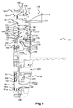
figure 1 est une vue en coupe longitudinale du dispositif complet, en position rapport court engagé, avec la machine électrique et l'extrémité de la boîte de vitesses, - la
figure 2 est une vue en coupe longitudinale du dispositif complet seul, en position neutre, - la
figure 3 est une vue en coupe longitudinale du dispositif complet seul, en position rapport long, et - la
figure 4 est une vue en coupe transversale du dispositif en représentation partielle. - Sur la
figure 1 , on a représenté en coupe longitudinale, un mode de réalisation du dispositif de traction hybride complet. L'hybridation de la boîte consiste à connecter à cette dernière une machine électrique par une liaison mécanique. Cette connexion présente deux niveaux : le premier est un réducteur de vitesses à deux rapports par l'utilisation d'un train épicycloïdal et le second est une simple transmission par chaîne. Le dispositif de traction hybride pour véhicule automobile décrit sur les figures, comporte une boîte de vitesses à arbres parallèles 200 dont un arbre primaire 202 transmet la puissance d'un moteur thermique d'entraînement à un arbre secondaire 203 relié aux roues du véhicule, et une machine électrique 300 transmettant sa puissance à l'arbre secondaire de la boîte 200. - Le mécanisme de transmission de puissance 100 est un mécanisme décrabotable 100 à deux rapports, entre la machine électrique 300 et l'arbre 203 de la boîte de vitesses, qui est relié mécaniquement avec cet arbre. Il comprend une enceinte composée d'une platine de support des mécanismes 101, et d'un carter de fermeture 102. L'ensemble du mécanisme est supporté par la platine 101, et contenu dans le carter 102, qui constitue un ensemble étanche possédant son propre lubrifiant.
- Il comporte un réducteur de vitesses, constitué par un train épicycloïdal simple 110, muni d'un planétaire 112 rapporté sur de cannelures sur un manchon support 111, qui est couplé en permanence avec la machine électrique 300, par exemple par une liaison cannelée. Le manchon 111 est supporté par un roulement à billes 114 centré dans le carter 102. Il est retenu et maintenu axialement par une plaque d'arrêt 116 qui présente une cannelure 116,a sur sa périphérie extérieure. Le manchon 111 supporte le planétaire 112 du train. Il est monté sur des cannelures, et retenu par l'anneau d'arrêt 113. Un joint dynamique d'étanchéité 118 du mécanisme de transmission 100 vers la machine électrique 300, est installé entre le manchon 111 et le carter 102. Le manchon 111 supporte également le porte-satellites 119. Sans assurer réellement son centrage, il limite son débattement axial par l'intermédiaire des butées à aiguilles 123, et lui offre un maintien axial par l'intermédiaire de la rondelle d'appui 124 contre le planétaire 112. Le porte-satellites 119 supporte trois satellites 120 guidés sur des aiguilles 121, et maintenus axialement par les rondelles de friction 122. Le dernier élément du train est la couronne 126, qui est centrée et entraînée en rotation par des excroissances régulières de la cloche du train planétaire 125. La cloche 125 supporte aussi un clabot 127 de blocage de train, qui est lié à la cloche 125 de la même manière que la couronne. La cloche et le clabot sont retenus axialement par l'anneau d'arrêt 128.
- La machine électrique 300 est connectée de manière permanente au planétaire 112 du train épicycloïdal, dont la couronne 126 est reliée mécaniquement à l'arbre secondaire 203 de la boîte. La seconde partie du mécanisme de transmission est composée principalement d'une chaîne 154, installée entre un pignon d'entrée 150, lié à la cloche 125 du train planétaire 110, et un pignon de sortie 155, porté par l'arbre secondaire 203 de la boîte de vitesses 200. La transmission mécanique entre le train épicycloïdal et l'arbre secondaire 203, est assurée par la chaîne 154, qui tourne autour des deux pignons 150, 155, dont le premier est lié à la couronne 126 et le second à l'arbre secondaire 203.
- Le pignon d'entrée 150 est guidé sur la platine 101 par le roulement à billes 151. Il est maintenu axialement par la coupelle 152 et la vis 153. Le planétaire 112 et le premier pignon, ou pignon d'entrée de chaîne 155, sont guidés radialement et maintenus axialement par cet unique roulement à bille 151. Avant le montage du mécanisme proposé sur la boîte, le pignon de sortie de chaîne 155 est pré centré par son moyeu 155,a sur le nez 101,a de la platine101. Il est guidé par une excroissance cannelée 203,a de l'arbre secondaire, et tenu axialement par des butées à aiguilles 157, ou en variante, par une rondelle de friction adaptée.
- Le pignon 155 possède en périphérie des dents d'engrènement avec la chaîne. Il assure l'étanchéité du mécanisme, du côté de sa liaison avec la boîte de vitesses 100, grâce à son obturateur 156, et à sa portée pour le joint dynamique 158, monté dans le carter 102. Ce pignon est maintenu axialement par deux butées à aiguilles 157, qui le prennent en sandwich entre la platine 101 et le carter 102. Pour fonctionner correctement, la chaîne nécessite une tension suffisante pour limiter la bruyance et l'usure.
- La machine électrique pouvant être motrice et réceptrice, la chaîne doit pouvoir travailler en « tiré » et en « poussé ». Les deux brins doivent pouvoir être tendus. Un mécanisme de tension mécanique autonome est installé à cet effet entre les deux brins. Il est constitué (voir
figure 4 ) d'un axe 180 dans la platine 101, de deux bras 181 supportant chacun un patin 183, articulé sur un axe 182. Les deux patins sont repoussés mutuellement contre les brins de la chaîne 154, par le ressort 184. Ce système est contenu dans une enceinte étanche composée d'une platine 101 et d'un carter 102. - La boîte 200 partiellement représentée sur la
figure 1 comprend un carter de mécanisme 201, un arbre primaire 202, un arbre secondaire 203. Ce dernier présente une excroissance cannelée 203,a, dépassant à l'extrémité du carter et accueillant le pignon de sortie 155 du dispositif d'hybridation. - Le mécanisme de transmission 100 est à deux rapports. Comme indiqué plus haut, le train épicycloïdal possède un porte-satellites 119, possédant en périphérie une couronne une cannelure 119,a, et une rondelle clabot 127 liée à la couronne 126 du train par l'intermédiaire de la cloche 125. La plaque d'arrêt 116 du roulement supporte en périphérie un clabot de blocage 116,a. Lorsque les cannelures 119,a du porte-satellites et le clabot de blocage 116,a sont liés, et le porte-satellites est bloqué à l'arrêt. Cette position est illustrée par la
figure 1 . Elle réalise une réduction de vitesses (ou multiplication de couple) par le train, dans le rapport du nombre des dents du planétaire 112 et de la couronne 126. Le dispositif de transmission est sur son rapport court. Lorsque les cannelures 119,a et le clabot 127 sont liés, et le porte-satellites 119 et la couronne 126 sont liés. Dans cette position, illustrée par lafigure 3 , l'ensemble du train tourne à la même vitesse. Le rapport de démultiplication est de un. C'est le rapport long du dispositif. Dans une situation intermédiaire, illustrée par lafigure 2 , le porte-satellites n'est lié ni à la couronne, 126 ni à la plaque d'arrêt 116. Il est libre en rotation, de sorte que la machine électrique est alors découplée du GMP. Le dispositif est en position neutre. En résumé, le train épicycloïdal présente un rapport court sur lequel son porte-satellites 119 est immobilisé vis-à-vis d'un carter 102 et un rapport long, où il tourne en bloc, et une position une position neutre, où le mécanisme est déconnecté de la machine électrique 300. - Un dispositif de commande est prévu pour réaliser ces changements de rapports. Il est constitué d'un baladeur 170 actionné par un moteur auxiliaire 178. Le baladeur 170 se présente sous la forme d'un manchon coulissant sur les cannelures 119,a du porte-satellites 119 entre une position de rapport court où il immobilise le porte-satellites 119 par crabotage sur les dents 116,a d'une plaque d'arrêt 116 fixée au carter 102 et une position de rapport long où il lie en rotation le porte-satellites 119 à la couronne 126, en passant par une position intermédiaire, libre par rapport à ces deux éléments, où le mécanisme de transmission 100 est déconnecté de la machine électrique 300. Entre ces deux positions, il passe par le neutre.
- Le baladeur 170 est entouré partiellement par la fourchette de commande 171, portée par un axe 172, qui est guidé dans la platine de support 101 et dans le carter 102 par des bagues 173. Le manchon coulissant 170 est actionné par la fourchette 171. Celle-ci porte un bras d'actionnement, lui-même déplacé par une tige filetée, qui est animée par le moteur électrique piloté 178.
- La fourchette 171 présente une excroissance 171,a avec un alésage fileté, qui coopère avec un axe 174 entraîné par le moteur 178. L'axe 174 est fileté dans sa partie centrale, et guidé dans la platine de support 101,e sur le carter 102. Il est arrêté axialement contre ces deux éléments par les rondelles de friction 176. L'axe 174 traverse le carter 102. Le joint 177 réalise une étanchéité. Le moteur 187 assure le déplacement du baladeur entre ses trois positions.
- La
figure 4 met en évidence le moyen de tension mécanique de la chaîne, qui est composé de deux patins 183 supportés par deux bras articulés 181 autour d'un axe commun 180, et mutuellement repoussés par un ressort pré-chargé 184. En fonctionnement, l'un des brins de la chaîne se tend, tandis que l'autre se détend. Lorsque la machine électrique passe d'un fonctionnement « en motrice » à un fonctionnement « en génératrice », le brin tendu et le brin détendu s'inversent. Grâce au système de tension proposé, le brin de chaîne détendu est toujours retendu par son patin qui prend appui sur le brin tendu par l'intermédiaire du ressort 184.
| Repères | |
| 100 | Mécanisme de transmission de puissance |
| 101 | Platine support de mécanisme de transmission de puissance électrique |
| 101,a | Pré-centrage du pignon 155 |
| 102 | Carter du mécanisme de transmission de puissance électrique |
| 110 | Train épicycloïdal |
| 111 | Manchon support de planétaire |
| 112 | Planétaire |
| 113 | Anneau d'arrêt planétaire |
| 114 | Roulement support du manchon de planétaire |
| 115 | Clip arrêt roulement |
| 116 | Plaque d'arrêt du roulement 114 |
| 116, a | Clabot de blocage du porte satellite |
| 117 | Vis de maintien de la plaque 115 |
| 118 | Joint d'étanchéité du manchon 111 |
| 119 | Porte-satellite |
| 119, a | Crabot du porte satellite |
| 120 | Satellite |
| 121 | Aiguilles sous satellite |
| 122 | Rondelle de friction satellite |
| 123 | Butées de porte satellite à aiguilles |
| 124 | Rondelle appui aiguilles |
| 125 | Cloche de train planétaire |
| 126 | Couronne |
| 127 | Clabot de blocage du train |
| 128 | Anneau d'arrêt du crabot 127 |
| 150 | Pignon d'entrée de chaîne |
| 151 | Roulement support du pignon 150 |
| 152 | Coupelle de maintien du roulement 150 |
| 153 | Vis maintien coupelle 152 |
| 154 | Chaîne |
| 155 | Pignon de sortie de chaîne |
| 155, a | Excroissance moyeu pour pré centrage |
| 156 | Obturateur sur pignon de chaîne 155 |
| 157 | Butée à aiguilles maintien axial du pignon 150 |
| 158 | Joint étanchéité |
| 170 | Baladeur de clabotage |
| 171 | Fourchette de commande clabot |
| 172 | Axe de fourchette |
| 173 | Bague de guidage fourchette |
| 174 | Axe vis de commande fourchette |
| 175 | Bague de guidage vis |
| 176 | Rondelle appui vis |
| 177 | Joint étanchéité axe vis |
| 178 | Moteur de commande clabotage |
| 180 | Axe du tendeur |
| 181 | Bras articulé |
| 182 | Axe de patin |
| 183 | patin |
| 184 | ressort |
| 200 | Boîte de vitesses |
| 201 | Carter des mécanismes |
| 202 | Arbre primaire |
| 203 | Arbre secondaire |
| 203, a | Embout cannelée de l'arbre secondaire |
| 204 | Joint étanchéité boîte |
| 300 | Machine électrique moteur - générateur. |
Claims (12)
- Dispositif de traction hybride pour véhicule automobile comportant une boîte de vitesses à arbres parallèles (200) dont un arbre primaire (202) transmet la puissance d'un moteur thermique d'entraînement à un arbre secondaire (203) relié aux roues du véhicule, une machine électrique (300) transmettant sa puissance à l'arbre secondaire de la boîte (200), et un mécanisme de transmission de puissance (100) agencé entre la machine électrique et l'arbre secondaire de la boîte de vitesses comprenant un train épicycloïdal (110) à deux rapports, relié mécaniquement avec l'arbre secondaire (203), caractérisé en ce que la machine électrique (300) est connectée de manière permanente au planétaire (112) du train épicycloïdal, dont la couronne (126) est reliée mécaniquement à l'arbre secondaire (203) de la boîte de vitesses.
- Dispositif de traction hybride selon la revendication 1, caractérisé en ce que la transmission mécanique entre le train épicycloïdal (110) et l'arbre secondaire (203) de la boîte est assurée par une chaîne (154) tournant autour de deux pignons (150, 155), dont le premier est lié à la couronne (126) du train épicycloïdal et le second à l'arbre secondaire (203).
- Dispositif de traction hybride selon la revendication 1 ou 2, caractérisé en ce que le train épicycloïdal (110) présente un rapport court sur lequel son porte-satellites (119) est immobilisé vis-à-vis d'un carter (102), et un rapport long, où il tourne en bloc.
- Dispositif de traction hybride selon la revendication 3, caractérisé en ce qu'il présente un manchon (170) coulissant sur les cannelures (119,a) du porte-satellites (119) entre une position de rapport court où il immobilise le porte-satellites (119) par crabotage sur les dents (116,a) d'une plaque d'arrêt (116) fixée au carter (102) et une position de rapport long où il lie en rotation le porte-satellites (119) à la couronne (126), en passant par une position intermédiaire, libre par rapport à ces deux éléments, où le mécanisme de transmission (100) est déconnecté de la machine électrique (300).
- Mécanisme de transmission de puissance décrabotable (100) à deux rapports, entre une machine électrique et un arbre de boîte de vitesses, caractérisé en ce qu'il est composé d'un train épicycloïdal (110) à deux rapports, relié mécaniquement avec l'arbre secondaire (203) de la boîte de vitesses, la machine électrique (300) étant connectée de manière permanente au planétaire (112) du train épicycloïdal, dont la couronne (126) est reliée mécaniquement à l'arbre secondaire (203).
- Mécanisme de transmission de puissance (100) selon la revendication 5, caractérisé en ce que la liaison mécanique entre le train épicycloïdal et l'arbre secondaire (203) est assurée par une chaîne (154) tournant autour de deux pignons (150, 155), dont le premier est lié à la couronne (126) du train épicycloïdal et le second à l'arbre secondaire (203).
- Mécanisme de transmission de puissance (100) selon la revendication 5 ou 6, caractérisé en ce qu'il présente un manchon (170) coulissant sur les cannelures (119,a) du porte-satellites (119) entre une position de rapport court où il immobilise le porte-satellites (119) par crabotage sur les dents 116,a d'une plaque d'arrêt (116) fixée au carter (102) et une position de rapport long où il lie en rotation le porte-satellites 119 à la couronne (126), en passant par une position intermédiaire, libre par rapport à ces deux éléments, où le mécanisme de transmission (100) est déconnecté de la machine électrique (300).
- Mécanisme de transmission de puissance (100) selon la revendication 7, caractérisé en ce que le manchon coulissant (170) est actionné par une fourchette (171) de commande portant un bras déplacé par une tige filetée qui est animée par un moteur électrique piloté (178).
- Mécanisme de transmission de puissance (100) selon la revendication 6, 7 ou 8, caractérisé en ce que la chaîne (154) présente une cloche (125), la cloche (125), la couronne (126), et le premier pignon (150) de la chaîne (154) étant guidés radialement et maintenus axialement par un unique roulement à billes (151).
- Mécanisme de transmission de puissance (100) selon l'une des revendications 6 à 9, caractérisé en ce que le pignon de sortie de chaîne (155) est guidé par une excroissance cannelée (203,a) de l'arbre secondaire et tenu axialement par des butées à aiguilles ( 157) ou par une rondelle de friction adaptée.
- Mécanisme de transmission de puissance (100) selon l'une des revendications 6 à 10, caractérisé en ce que la chaîne (154) possède un moyen de tension mécanique composé de deux patins (183) supporté par deux bras articulés (181) autour d'un axe commun (180) et mutuellement repoussés par un ressort pré-chargé ( 184).
- Mécanisme de transmission de puissance (100) selon l'une des revendications 6 à 11, caractérisé en ce qu'il est supporté par une platine (101) et contenu dans un carter (102) qui constitue un ensemble étanche possédant son propre lubrifiant.
Applications Claiming Priority (1)
| Application Number | Priority Date | Filing Date | Title |
|---|---|---|---|
| FR1460704A FR3028218B1 (fr) | 2014-11-06 | 2014-11-06 | Dispositif de traction hybride de vehicule automobile et mecanisme de transmission de puissance |
Publications (2)
| Publication Number | Publication Date |
|---|---|
| EP3017987A1 true EP3017987A1 (fr) | 2016-05-11 |
| EP3017987B1 EP3017987B1 (fr) | 2020-04-29 |
Family
ID=52477847
Family Applications (1)
| Application Number | Title | Priority Date | Filing Date |
|---|---|---|---|
| EP15185795.0A Active EP3017987B1 (fr) | 2014-11-06 | 2015-09-18 | Dispositif de traction hybride de véhicule automobile et mécanisme de transmission de puissance |
Country Status (2)
| Country | Link |
|---|---|
| EP (1) | EP3017987B1 (fr) |
| FR (1) | FR3028218B1 (fr) |
Cited By (1)
| Publication number | Priority date | Publication date | Assignee | Title |
|---|---|---|---|---|
| WO2018041915A1 (fr) * | 1968-11-29 | 2018-03-08 | Borgwarner Sweden Ab | Module d'entraînement hybride |
Citations (6)
| Publication number | Priority date | Publication date | Assignee | Title |
|---|---|---|---|---|
| FR2772675A1 (fr) | 1997-12-22 | 1999-06-25 | Renault | Dispositif de transmission de vehicule automobile a motorisation hybride comportant un accouplement commande du moteur electrique |
| US20110179890A1 (en) * | 2010-01-25 | 2011-07-28 | Gm Global Technology Operations, Inc. | Hybrid powertrain with single motor/generator connected to final drive assembly and method of assembly |
| WO2013007886A1 (fr) * | 2011-07-13 | 2013-01-17 | IFP Energies Nouvelles | Groupe motopropulseur pour véhicule automobile à entraînement hybride |
| DE102012016990A1 (de) * | 2012-07-02 | 2014-01-02 | Volkswagen Aktiengesellschaft | Hybridantriebsstrang für ein Kraftfahrzeug, Hybridfahrzeug und Verwendung desselben |
| WO2014032961A1 (fr) * | 2012-08-25 | 2014-03-06 | Volkswagen Aktiengesellschaft | Chaîne cinématique hybride pour véhicule automobile, véhicule hybride et son utilisation |
| DE102012024677A1 (de) * | 2012-12-18 | 2014-06-18 | Getrag Getriebe- Und Zahnradfabrik Hermann Hagenmeyer Gmbh & Cie Kg | Hybrid-Antriebsstrang und Gangstufenwechselverfahren |
Family Cites Families (1)
| Publication number | Priority date | Publication date | Assignee | Title |
|---|---|---|---|---|
| DE102012007622A1 (de) * | 2012-04-18 | 2013-10-24 | Voith Patent Gmbh | Verfahren zum Durchführen eines Schaltschritts |
-
2014
- 2014-11-06 FR FR1460704A patent/FR3028218B1/fr not_active Expired - Fee Related
-
2015
- 2015-09-18 EP EP15185795.0A patent/EP3017987B1/fr active Active
Patent Citations (6)
| Publication number | Priority date | Publication date | Assignee | Title |
|---|---|---|---|---|
| FR2772675A1 (fr) | 1997-12-22 | 1999-06-25 | Renault | Dispositif de transmission de vehicule automobile a motorisation hybride comportant un accouplement commande du moteur electrique |
| US20110179890A1 (en) * | 2010-01-25 | 2011-07-28 | Gm Global Technology Operations, Inc. | Hybrid powertrain with single motor/generator connected to final drive assembly and method of assembly |
| WO2013007886A1 (fr) * | 2011-07-13 | 2013-01-17 | IFP Energies Nouvelles | Groupe motopropulseur pour véhicule automobile à entraînement hybride |
| DE102012016990A1 (de) * | 2012-07-02 | 2014-01-02 | Volkswagen Aktiengesellschaft | Hybridantriebsstrang für ein Kraftfahrzeug, Hybridfahrzeug und Verwendung desselben |
| WO2014032961A1 (fr) * | 2012-08-25 | 2014-03-06 | Volkswagen Aktiengesellschaft | Chaîne cinématique hybride pour véhicule automobile, véhicule hybride et son utilisation |
| DE102012024677A1 (de) * | 2012-12-18 | 2014-06-18 | Getrag Getriebe- Und Zahnradfabrik Hermann Hagenmeyer Gmbh & Cie Kg | Hybrid-Antriebsstrang und Gangstufenwechselverfahren |
Cited By (3)
| Publication number | Priority date | Publication date | Assignee | Title |
|---|---|---|---|---|
| WO2018041915A1 (fr) * | 1968-11-29 | 2018-03-08 | Borgwarner Sweden Ab | Module d'entraînement hybride |
| CN109641514A (zh) * | 1968-11-29 | 2019-04-16 | 博格华纳瑞典公司 | 混合驱动模块 |
| US11091020B2 (en) | 1968-11-29 | 2021-08-17 | Borgwarner Sweden Ab | Hybrid drive module with chain drive oil lid |
Also Published As
| Publication number | Publication date |
|---|---|
| FR3028218A1 (fr) | 2016-05-13 |
| FR3028218B1 (fr) | 2018-03-09 |
| EP3017987B1 (fr) | 2020-04-29 |
Similar Documents
| Publication | Publication Date | Title |
|---|---|---|
| FR2805587A1 (fr) | Dispositif de transmission automatise a engrenages, en particulier pour vehicule automobile | |
| FR2821137A1 (fr) | Systeme de transmission de mouvement pour vehicules a propulsion hybride | |
| CA2615936C (fr) | Engrenage a protection de surcouple integree | |
| FR3021594A1 (fr) | Dispositif de transmission de vitesse pour le deplacement d'un vehicule automobile, notamment d'un vehicule motorise a deux-roues. | |
| FR2512512A1 (fr) | Limiteur de couple pour engrenage de reduction a planetaires | |
| WO2016120066A1 (fr) | Procédé de commande d'un dispositif de transmission à variation de vitesse à trains épicycloïdaux d'un groupe motopropulseur, en particulier pour véhicule hybride | |
| EP3017987B1 (fr) | Dispositif de traction hybride de véhicule automobile et mécanisme de transmission de puissance | |
| FR2959544A1 (fr) | Dispositif de synchronisation pour boite de vitesses et boite de vitesses le comportant | |
| FR3071576B1 (fr) | Dispositif de transmission de vitesse avec marche arriere pour le deplacement d'un vehicule automobile, notamment d'un vehicule motorise a au moins deux-roues | |
| FR2470704A1 (fr) | Montage du moteur et de la transmission dans un vehicule, en particulier une voiture automobile | |
| WO2015078645A1 (fr) | Groupe motopropulseur de vehicule et vehicule | |
| WO2016091655A1 (fr) | Groupe motopropulseur pour l'entraînement d'un véhicule automobile avec un dispositif de transmission à variation de vitesse à double train épicycloïdal et en particulier groupe motopropulseur pour un véhicule de type hybride | |
| WO2016087434A1 (fr) | Dispositif de transmission de vitesse pour le déplacement d'un véhicule automobile, notamment d'un véhicule motorisé à au moins deux roues, et groupe motopropulseur utilisant un tel dispositif en particulier pour un véhicule hybride | |
| EP3931464B1 (fr) | Dispositif de transmission de couple pour un vehicule automobile | |
| CA2615038C (fr) | Engrenage a protection de surcouple integree | |
| FR3127270A1 (fr) | Mécanisme de transmission et ensemble de propulsion associé | |
| EP3699008A1 (fr) | Dispositif de traction hybride de vehicule automobile et mecanisme de transmission de puissance | |
| WO2015086325A1 (fr) | Groupe motopropulseur avec un dispositif de transmission à variation de vitesse, en particulier pour véhicule hybride | |
| FR3106089A1 (fr) | Transmission automatique pour véhicule hybride thermique/électrique | |
| FR2847014A1 (fr) | Transmission infiniment variable a derivation de puissance, a variateur electrique et train compose | |
| FR2566718A1 (fr) | Dispositif de transmission entre un arbre moteur et deux arbres recepteurs, notamment pour l'entrainement d'une boite de vitesses | |
| FR2682444A1 (fr) | Dispositif de changement de vitesses automatique a convertisseur de couple et train epicyclouidal non coaxiaux. | |
| WO2018054717A1 (fr) | Groupe motopropulseur de vehicule automobile | |
| FR3077536A1 (fr) | Dispositif de transmission a deux vitesses pour vehicule electrique | |
| WO2015011414A1 (fr) | Transmission automatique et procédé de commande correspondant |
Legal Events
| Date | Code | Title | Description |
|---|---|---|---|
| PUAI | Public reference made under article 153(3) epc to a published international application that has entered the european phase |
Free format text: ORIGINAL CODE: 0009012 |
|
| AK | Designated contracting states |
Kind code of ref document: A1 Designated state(s): AL AT BE BG CH CY CZ DE DK EE ES FI FR GB GR HR HU IE IS IT LI LT LU LV MC MK MT NL NO PL PT RO RS SE SI SK SM TR |
|
| AX | Request for extension of the european patent |
Extension state: BA ME |
|
| 17P | Request for examination filed |
Effective date: 20161003 |
|
| RBV | Designated contracting states (corrected) |
Designated state(s): AL AT BE BG CH CY CZ DE DK EE ES FI FR GB GR HR HU IE IS IT LI LT LU LV MC MK MT NL NO PL PT RO RS SE SI SK SM TR |
|
| REG | Reference to a national code |
Ref country code: DE Ref legal event code: R079 Ref document number: 602015051522 Country of ref document: DE Free format text: PREVIOUS MAIN CLASS: B60K0006480000 Ipc: F16H0003540000 |
|
| STAA | Information on the status of an ep patent application or granted ep patent |
Free format text: STATUS: REQUEST FOR EXAMINATION WAS MADE |
|
| STAA | Information on the status of an ep patent application or granted ep patent |
Free format text: STATUS: EXAMINATION IS IN PROGRESS |
|
| RIC1 | Information provided on ipc code assigned before grant |
Ipc: B60K 6/48 20071001ALI20181211BHEP Ipc: B60K 6/54 20071001ALI20181211BHEP Ipc: B60K 6/365 20071001ALI20181211BHEP Ipc: F16H 3/54 20060101AFI20181211BHEP |
|
| 17Q | First examination report despatched |
Effective date: 20190103 |
|
| RIC1 | Information provided on ipc code assigned before grant |
Ipc: F16H 3/54 20060101AFI20181211BHEP Ipc: B60K 6/365 20071001ALI20181211BHEP Ipc: B60K 6/54 20071001ALI20181211BHEP Ipc: B60K 6/48 20071001ALI20181211BHEP |
|
| GRAP | Despatch of communication of intention to grant a patent |
Free format text: ORIGINAL CODE: EPIDOSNIGR1 |
|
| STAA | Information on the status of an ep patent application or granted ep patent |
Free format text: STATUS: GRANT OF PATENT IS INTENDED |
|
| INTG | Intention to grant announced |
Effective date: 20191121 |
|
| GRAS | Grant fee paid |
Free format text: ORIGINAL CODE: EPIDOSNIGR3 |
|
| GRAA | (expected) grant |
Free format text: ORIGINAL CODE: 0009210 |
|
| STAA | Information on the status of an ep patent application or granted ep patent |
Free format text: STATUS: THE PATENT HAS BEEN GRANTED |
|
| AK | Designated contracting states |
Kind code of ref document: B1 Designated state(s): AL AT BE BG CH CY CZ DE DK EE ES FI FR GB GR HR HU IE IS IT LI LT LU LV MC MK MT NL NO PL PT RO RS SE SI SK SM TR |
|
| REG | Reference to a national code |
Ref country code: GB Ref legal event code: FG4D Free format text: NOT ENGLISH |
|
| REG | Reference to a national code |
Ref country code: CH Ref legal event code: EP |
|
| REG | Reference to a national code |
Ref country code: AT Ref legal event code: REF Ref document number: 1263798 Country of ref document: AT Kind code of ref document: T Effective date: 20200515 |
|
| REG | Reference to a national code |
Ref country code: DE Ref legal event code: R096 Ref document number: 602015051522 Country of ref document: DE |
|
| REG | Reference to a national code |
Ref country code: IE Ref legal event code: FG4D Free format text: LANGUAGE OF EP DOCUMENT: FRENCH |
|
| REG | Reference to a national code |
Ref country code: NL Ref legal event code: MP Effective date: 20200429 |
|
| REG | Reference to a national code |
Ref country code: LT Ref legal event code: MG4D |
|
| PG25 | Lapsed in a contracting state [announced via postgrant information from national office to epo] |
Ref country code: NO Free format text: LAPSE BECAUSE OF FAILURE TO SUBMIT A TRANSLATION OF THE DESCRIPTION OR TO PAY THE FEE WITHIN THE PRESCRIBED TIME-LIMIT Effective date: 20200729 Ref country code: IS Free format text: LAPSE BECAUSE OF FAILURE TO SUBMIT A TRANSLATION OF THE DESCRIPTION OR TO PAY THE FEE WITHIN THE PRESCRIBED TIME-LIMIT Effective date: 20200829 Ref country code: PT Free format text: LAPSE BECAUSE OF FAILURE TO SUBMIT A TRANSLATION OF THE DESCRIPTION OR TO PAY THE FEE WITHIN THE PRESCRIBED TIME-LIMIT Effective date: 20200831 Ref country code: GR Free format text: LAPSE BECAUSE OF FAILURE TO SUBMIT A TRANSLATION OF THE DESCRIPTION OR TO PAY THE FEE WITHIN THE PRESCRIBED TIME-LIMIT Effective date: 20200730 Ref country code: FI Free format text: LAPSE BECAUSE OF FAILURE TO SUBMIT A TRANSLATION OF THE DESCRIPTION OR TO PAY THE FEE WITHIN THE PRESCRIBED TIME-LIMIT Effective date: 20200429 Ref country code: SE Free format text: LAPSE BECAUSE OF FAILURE TO SUBMIT A TRANSLATION OF THE DESCRIPTION OR TO PAY THE FEE WITHIN THE PRESCRIBED TIME-LIMIT Effective date: 20200429 Ref country code: LT Free format text: LAPSE BECAUSE OF FAILURE TO SUBMIT A TRANSLATION OF THE DESCRIPTION OR TO PAY THE FEE WITHIN THE PRESCRIBED TIME-LIMIT Effective date: 20200429 |
|
| REG | Reference to a national code |
Ref country code: AT Ref legal event code: MK05 Ref document number: 1263798 Country of ref document: AT Kind code of ref document: T Effective date: 20200429 |
|
| PG25 | Lapsed in a contracting state [announced via postgrant information from national office to epo] |
Ref country code: BG Free format text: LAPSE BECAUSE OF FAILURE TO SUBMIT A TRANSLATION OF THE DESCRIPTION OR TO PAY THE FEE WITHIN THE PRESCRIBED TIME-LIMIT Effective date: 20200729 Ref country code: RS Free format text: LAPSE BECAUSE OF FAILURE TO SUBMIT A TRANSLATION OF THE DESCRIPTION OR TO PAY THE FEE WITHIN THE PRESCRIBED TIME-LIMIT Effective date: 20200429 Ref country code: LV Free format text: LAPSE BECAUSE OF FAILURE TO SUBMIT A TRANSLATION OF THE DESCRIPTION OR TO PAY THE FEE WITHIN THE PRESCRIBED TIME-LIMIT Effective date: 20200429 Ref country code: HR Free format text: LAPSE BECAUSE OF FAILURE TO SUBMIT A TRANSLATION OF THE DESCRIPTION OR TO PAY THE FEE WITHIN THE PRESCRIBED TIME-LIMIT Effective date: 20200429 |
|
| PG25 | Lapsed in a contracting state [announced via postgrant information from national office to epo] |
Ref country code: NL Free format text: LAPSE BECAUSE OF FAILURE TO SUBMIT A TRANSLATION OF THE DESCRIPTION OR TO PAY THE FEE WITHIN THE PRESCRIBED TIME-LIMIT Effective date: 20200429 Ref country code: AL Free format text: LAPSE BECAUSE OF FAILURE TO SUBMIT A TRANSLATION OF THE DESCRIPTION OR TO PAY THE FEE WITHIN THE PRESCRIBED TIME-LIMIT Effective date: 20200429 |
|
| PG25 | Lapsed in a contracting state [announced via postgrant information from national office to epo] |
Ref country code: ES Free format text: LAPSE BECAUSE OF FAILURE TO SUBMIT A TRANSLATION OF THE DESCRIPTION OR TO PAY THE FEE WITHIN THE PRESCRIBED TIME-LIMIT Effective date: 20200429 Ref country code: AT Free format text: LAPSE BECAUSE OF FAILURE TO SUBMIT A TRANSLATION OF THE DESCRIPTION OR TO PAY THE FEE WITHIN THE PRESCRIBED TIME-LIMIT Effective date: 20200429 Ref country code: EE Free format text: LAPSE BECAUSE OF FAILURE TO SUBMIT A TRANSLATION OF THE DESCRIPTION OR TO PAY THE FEE WITHIN THE PRESCRIBED TIME-LIMIT Effective date: 20200429 Ref country code: SM Free format text: LAPSE BECAUSE OF FAILURE TO SUBMIT A TRANSLATION OF THE DESCRIPTION OR TO PAY THE FEE WITHIN THE PRESCRIBED TIME-LIMIT Effective date: 20200429 Ref country code: DK Free format text: LAPSE BECAUSE OF FAILURE TO SUBMIT A TRANSLATION OF THE DESCRIPTION OR TO PAY THE FEE WITHIN THE PRESCRIBED TIME-LIMIT Effective date: 20200429 Ref country code: IT Free format text: LAPSE BECAUSE OF FAILURE TO SUBMIT A TRANSLATION OF THE DESCRIPTION OR TO PAY THE FEE WITHIN THE PRESCRIBED TIME-LIMIT Effective date: 20200429 Ref country code: CZ Free format text: LAPSE BECAUSE OF FAILURE TO SUBMIT A TRANSLATION OF THE DESCRIPTION OR TO PAY THE FEE WITHIN THE PRESCRIBED TIME-LIMIT Effective date: 20200429 Ref country code: RO Free format text: LAPSE BECAUSE OF FAILURE TO SUBMIT A TRANSLATION OF THE DESCRIPTION OR TO PAY THE FEE WITHIN THE PRESCRIBED TIME-LIMIT Effective date: 20200429 |
|
| REG | Reference to a national code |
Ref country code: DE Ref legal event code: R097 Ref document number: 602015051522 Country of ref document: DE |
|
| PG25 | Lapsed in a contracting state [announced via postgrant information from national office to epo] |
Ref country code: PL Free format text: LAPSE BECAUSE OF FAILURE TO SUBMIT A TRANSLATION OF THE DESCRIPTION OR TO PAY THE FEE WITHIN THE PRESCRIBED TIME-LIMIT Effective date: 20200429 Ref country code: SK Free format text: LAPSE BECAUSE OF FAILURE TO SUBMIT A TRANSLATION OF THE DESCRIPTION OR TO PAY THE FEE WITHIN THE PRESCRIBED TIME-LIMIT Effective date: 20200429 |
|
| PLBE | No opposition filed within time limit |
Free format text: ORIGINAL CODE: 0009261 |
|
| STAA | Information on the status of an ep patent application or granted ep patent |
Free format text: STATUS: NO OPPOSITION FILED WITHIN TIME LIMIT |
|
| 26N | No opposition filed |
Effective date: 20210201 |
|
| PG25 | Lapsed in a contracting state [announced via postgrant information from national office to epo] |
Ref country code: MC Free format text: LAPSE BECAUSE OF FAILURE TO SUBMIT A TRANSLATION OF THE DESCRIPTION OR TO PAY THE FEE WITHIN THE PRESCRIBED TIME-LIMIT Effective date: 20200429 |
|
| REG | Reference to a national code |
Ref country code: CH Ref legal event code: PL |
|
| GBPC | Gb: european patent ceased through non-payment of renewal fee |
Effective date: 20200918 |
|
| PG25 | Lapsed in a contracting state [announced via postgrant information from national office to epo] |
Ref country code: SI Free format text: LAPSE BECAUSE OF FAILURE TO SUBMIT A TRANSLATION OF THE DESCRIPTION OR TO PAY THE FEE WITHIN THE PRESCRIBED TIME-LIMIT Effective date: 20200429 |
|
| REG | Reference to a national code |
Ref country code: BE Ref legal event code: MM Effective date: 20200930 |
|
| PG25 | Lapsed in a contracting state [announced via postgrant information from national office to epo] |
Ref country code: LU Free format text: LAPSE BECAUSE OF NON-PAYMENT OF DUE FEES Effective date: 20200918 |
|
| PG25 | Lapsed in a contracting state [announced via postgrant information from national office to epo] |
Ref country code: GB Free format text: LAPSE BECAUSE OF NON-PAYMENT OF DUE FEES Effective date: 20200918 Ref country code: LI Free format text: LAPSE BECAUSE OF NON-PAYMENT OF DUE FEES Effective date: 20200930 Ref country code: IE Free format text: LAPSE BECAUSE OF NON-PAYMENT OF DUE FEES Effective date: 20200918 Ref country code: CH Free format text: LAPSE BECAUSE OF NON-PAYMENT OF DUE FEES Effective date: 20200930 Ref country code: BE Free format text: LAPSE BECAUSE OF NON-PAYMENT OF DUE FEES Effective date: 20200930 |
|
| PG25 | Lapsed in a contracting state [announced via postgrant information from national office to epo] |
Ref country code: TR Free format text: LAPSE BECAUSE OF FAILURE TO SUBMIT A TRANSLATION OF THE DESCRIPTION OR TO PAY THE FEE WITHIN THE PRESCRIBED TIME-LIMIT Effective date: 20200429 Ref country code: MT Free format text: LAPSE BECAUSE OF FAILURE TO SUBMIT A TRANSLATION OF THE DESCRIPTION OR TO PAY THE FEE WITHIN THE PRESCRIBED TIME-LIMIT Effective date: 20200429 Ref country code: CY Free format text: LAPSE BECAUSE OF FAILURE TO SUBMIT A TRANSLATION OF THE DESCRIPTION OR TO PAY THE FEE WITHIN THE PRESCRIBED TIME-LIMIT Effective date: 20200429 |
|
| PG25 | Lapsed in a contracting state [announced via postgrant information from national office to epo] |
Ref country code: MK Free format text: LAPSE BECAUSE OF FAILURE TO SUBMIT A TRANSLATION OF THE DESCRIPTION OR TO PAY THE FEE WITHIN THE PRESCRIBED TIME-LIMIT Effective date: 20200429 |
|
| P01 | Opt-out of the competence of the unified patent court (upc) registered |
Effective date: 20230608 |
|
| REG | Reference to a national code |
Ref country code: DE Ref legal event code: R081 Ref document number: 602015051522 Country of ref document: DE Owner name: NEW H POWERTRAIN HOLDING, S.L.U., ES Free format text: FORMER OWNER: RENAULT S.A.S., BOULOGNE-BILLANCOURT, FR |
|
| PGFP | Annual fee paid to national office [announced via postgrant information from national office to epo] |
Ref country code: DE Payment date: 20250919 Year of fee payment: 11 |
|
| PGFP | Annual fee paid to national office [announced via postgrant information from national office to epo] |
Ref country code: FR Payment date: 20250922 Year of fee payment: 11 |