EP3017971A1 - Tire sensor-based vehicle control system optimization and method - Google Patents
Tire sensor-based vehicle control system optimization and method Download PDFInfo
- Publication number
- EP3017971A1 EP3017971A1 EP15192575.7A EP15192575A EP3017971A1 EP 3017971 A1 EP3017971 A1 EP 3017971A1 EP 15192575 A EP15192575 A EP 15192575A EP 3017971 A1 EP3017971 A1 EP 3017971A1
- Authority
- EP
- European Patent Office
- Prior art keywords
- tire
- vehicle
- control system
- specific
- parameters
- Prior art date
- Legal status (The legal status is an assumption and is not a legal conclusion. Google has not performed a legal analysis and makes no representation as to the accuracy of the status listed.)
- Granted
Links
- 238000000034 method Methods 0.000 title claims abstract description 26
- 238000005457 optimization Methods 0.000 title description 4
- 230000003044 adaptive effect Effects 0.000 claims abstract description 12
- 230000004044 response Effects 0.000 claims abstract description 4
- 230000003319 supportive effect Effects 0.000 claims abstract 4
- 230000001133 acceleration Effects 0.000 claims description 9
- 230000000116 mitigating effect Effects 0.000 claims description 4
- 238000010276 construction Methods 0.000 description 16
- 238000000418 atomic force spectrum Methods 0.000 description 6
- 230000000694 effects Effects 0.000 description 6
- 230000035945 sensitivity Effects 0.000 description 6
- 238000004422 calculation algorithm Methods 0.000 description 5
- 238000012417 linear regression Methods 0.000 description 4
- 238000012360 testing method Methods 0.000 description 3
- 238000013528 artificial neural network Methods 0.000 description 2
- 230000014509 gene expression Effects 0.000 description 2
- 238000005259 measurement Methods 0.000 description 2
- 238000012544 monitoring process Methods 0.000 description 2
- 238000012935 Averaging Methods 0.000 description 1
- 230000004913 activation Effects 0.000 description 1
- 238000005452 bending Methods 0.000 description 1
- 230000009286 beneficial effect Effects 0.000 description 1
- 238000004364 calculation method Methods 0.000 description 1
- 230000015556 catabolic process Effects 0.000 description 1
- 238000011217 control strategy Methods 0.000 description 1
- 238000013016 damping Methods 0.000 description 1
- 230000003247 decreasing effect Effects 0.000 description 1
- 238000006731 degradation reaction Methods 0.000 description 1
- 230000001419 dependent effect Effects 0.000 description 1
- 238000013461 design Methods 0.000 description 1
- 230000006866 deterioration Effects 0.000 description 1
- 238000002224 dissection Methods 0.000 description 1
- 230000002093 peripheral effect Effects 0.000 description 1
- 238000004088 simulation Methods 0.000 description 1
- 230000003068 static effect Effects 0.000 description 1
Images


Classifications
-
- B—PERFORMING OPERATIONS; TRANSPORTING
- B60—VEHICLES IN GENERAL
- B60T—VEHICLE BRAKE CONTROL SYSTEMS OR PARTS THEREOF; BRAKE CONTROL SYSTEMS OR PARTS THEREOF, IN GENERAL; ARRANGEMENT OF BRAKING ELEMENTS ON VEHICLES IN GENERAL; PORTABLE DEVICES FOR PREVENTING UNWANTED MOVEMENT OF VEHICLES; VEHICLE MODIFICATIONS TO FACILITATE COOLING OF BRAKES
- B60T8/00—Arrangements for adjusting wheel-braking force to meet varying vehicular or ground-surface conditions, e.g. limiting or varying distribution of braking force
- B60T8/17—Using electrical or electronic regulation means to control braking
- B60T8/176—Brake regulation specially adapted to prevent excessive wheel slip during vehicle deceleration, e.g. ABS
-
- B—PERFORMING OPERATIONS; TRANSPORTING
- B60—VEHICLES IN GENERAL
- B60C—VEHICLE TYRES; TYRE INFLATION; TYRE CHANGING; CONNECTING VALVES TO INFLATABLE ELASTIC BODIES IN GENERAL; DEVICES OR ARRANGEMENTS RELATED TO TYRES
- B60C23/00—Devices for measuring, signalling, controlling, or distributing tyre pressure or temperature, specially adapted for mounting on vehicles; Arrangement of tyre inflating devices on vehicles, e.g. of pumps or of tanks; Tyre cooling arrangements
- B60C23/02—Signalling devices actuated by tyre pressure
- B60C23/04—Signalling devices actuated by tyre pressure mounted on the wheel or tyre
-
- B—PERFORMING OPERATIONS; TRANSPORTING
- B60—VEHICLES IN GENERAL
- B60C—VEHICLE TYRES; TYRE INFLATION; TYRE CHANGING; CONNECTING VALVES TO INFLATABLE ELASTIC BODIES IN GENERAL; DEVICES OR ARRANGEMENTS RELATED TO TYRES
- B60C19/00—Tyre parts or constructions not otherwise provided for
-
- B—PERFORMING OPERATIONS; TRANSPORTING
- B60—VEHICLES IN GENERAL
- B60C—VEHICLE TYRES; TYRE INFLATION; TYRE CHANGING; CONNECTING VALVES TO INFLATABLE ELASTIC BODIES IN GENERAL; DEVICES OR ARRANGEMENTS RELATED TO TYRES
- B60C23/00—Devices for measuring, signalling, controlling, or distributing tyre pressure or temperature, specially adapted for mounting on vehicles; Arrangement of tyre inflating devices on vehicles, e.g. of pumps or of tanks; Tyre cooling arrangements
- B60C23/02—Signalling devices actuated by tyre pressure
- B60C23/04—Signalling devices actuated by tyre pressure mounted on the wheel or tyre
- B60C23/0408—Signalling devices actuated by tyre pressure mounted on the wheel or tyre transmitting the signals by non-mechanical means from the wheel or tyre to a vehicle body mounted receiver
-
- B—PERFORMING OPERATIONS; TRANSPORTING
- B60—VEHICLES IN GENERAL
- B60C—VEHICLE TYRES; TYRE INFLATION; TYRE CHANGING; CONNECTING VALVES TO INFLATABLE ELASTIC BODIES IN GENERAL; DEVICES OR ARRANGEMENTS RELATED TO TYRES
- B60C23/00—Devices for measuring, signalling, controlling, or distributing tyre pressure or temperature, specially adapted for mounting on vehicles; Arrangement of tyre inflating devices on vehicles, e.g. of pumps or of tanks; Tyre cooling arrangements
- B60C23/06—Signalling devices actuated by deformation of the tyre, e.g. tyre mounted deformation sensors or indirect determination of tyre deformation based on wheel speed, wheel-centre to ground distance or inclination of wheel axle
-
- B—PERFORMING OPERATIONS; TRANSPORTING
- B60—VEHICLES IN GENERAL
- B60T—VEHICLE BRAKE CONTROL SYSTEMS OR PARTS THEREOF; BRAKE CONTROL SYSTEMS OR PARTS THEREOF, IN GENERAL; ARRANGEMENT OF BRAKING ELEMENTS ON VEHICLES IN GENERAL; PORTABLE DEVICES FOR PREVENTING UNWANTED MOVEMENT OF VEHICLES; VEHICLE MODIFICATIONS TO FACILITATE COOLING OF BRAKES
- B60T8/00—Arrangements for adjusting wheel-braking force to meet varying vehicular or ground-surface conditions, e.g. limiting or varying distribution of braking force
- B60T8/17—Using electrical or electronic regulation means to control braking
- B60T8/176—Brake regulation specially adapted to prevent excessive wheel slip during vehicle deceleration, e.g. ABS
- B60T8/1761—Brake regulation specially adapted to prevent excessive wheel slip during vehicle deceleration, e.g. ABS responsive to wheel or brake dynamics, e.g. wheel slip, wheel acceleration or rate of change of brake fluid pressure
- B60T8/17613—Brake regulation specially adapted to prevent excessive wheel slip during vehicle deceleration, e.g. ABS responsive to wheel or brake dynamics, e.g. wheel slip, wheel acceleration or rate of change of brake fluid pressure based on analogue circuits or digital circuits comprised of discrete electronic elements
-
- B—PERFORMING OPERATIONS; TRANSPORTING
- B60—VEHICLES IN GENERAL
- B60C—VEHICLE TYRES; TYRE INFLATION; TYRE CHANGING; CONNECTING VALVES TO INFLATABLE ELASTIC BODIES IN GENERAL; DEVICES OR ARRANGEMENTS RELATED TO TYRES
- B60C19/00—Tyre parts or constructions not otherwise provided for
- B60C2019/004—Tyre sensors other than for detecting tyre pressure
Definitions
- the invention relates generally to tire monitoring systems for collecting measured tire parameter data during vehicle operation and, more particularly, to a system and methods utilizing such tire sensor-based data in vehicle control systems.
- Vehicle-mounted tires during operation undergo considerable variation in tire properties such as braking stiffness, peak grip, and force-slip curve shape. Such variations may affect the performance of certain vehicle control systems such anti-lock braking systems. It is accordingly a desired objective to mitigate the effect of tire characteristic variability on such control systems and avoid degradation in performance.
- the invention relates to a system in accordance with claim 1 and to methods in accordance with claims 7 and 8 respectively.
- a system and method of controlling a vehicle in which multiple tire-based sensors are mounted to a vehicle tire to sense certain tire-derivative information.
- An adaptive tire model processes the tire-derivative information to continuously generate in real-time revisions to multiple tire-specific performance parameters.
- a vehicle control system(s) such as an anti-lock brake system and/or a collision mitigation braking system receives and applies in real-time the revisions to the tire-specific performance parameters to optimize the performance of the vehicle control system.
- the tire-specific performance parameters that may be used to adjust the vehicle control system are selected from the group tire braking stiffness, tire optimal slip point, tire shape factor and tire peak grip.
- the tire-derivative information may include tire make and type, tire inflation pressure, tire temperature and tire tread wear state.
- adjustment of the anti-lock brake system by revisions to the tire-specific performance parameters is made as an adjustment to the acceleration and deceleration thresholds for the vehicle anti-lock brake system.
- ANN Artificial Neural Network
- ANN neural networks are non-linear statistical data modeling tools used to model complex relationships between inputs and outputs or to find patterns in data.
- Axial and “axially” means lines or directions that are parallel to the axis of rotation of the tire.
- “Circumferential” means lines or directions extending along the perimeter of the surface of the annular tread perpendicular to the axial direction.
- “Lateral” means an axial direction.
- Piezoelectric Film Sensor a device in the form of a film body that uses the piezoelectric effect actuated by a bending of the film body to measure pressure, acceleration, strain or force by converting them to an electrical charge.
- Ring and radially means directions radially toward or away from the axis of rotation of the tire.
- a normalized force [ ⁇ ] to slip ratio [ ⁇ ] is shown comparing a "normal” tire at temperature 30°C with a cold tire at temperature of 0°C.
- "normal” refers to a tire at a normal operating temperature of 30°C.
- the cold tire has a 40 to 45 percent higher braking stiffness; that is the optimal slip-ratio change point changes by approximately 50 percent.
- a tire is subjected to large variations in operating conditions such as temperature, inflation pressure and changing tread depth as the tire ages.
- the subject control system employs tire identification (ID) in order to identify tire construction (summer/winter/all-season) with tire-attached tire pressure monitoring system (TPMS) devices to deliver tire temperature and pressure data in order to predict this change in the tire-force curve.
- ID tire identification
- TPMS tire pressure monitoring system
- tire sensed information thus includes tire ID (used to ascertain tire construction type) and TPMS data (pressure and temperature) applied to predict the tire-force curve.
- the ABS can be adapted to recover the drop in efficiency through threshold optimization and thereby improve braking distance.
- the graphs of FIG. 2 show the results of a sensitivity study on achievable braking performance.
- the tire tested was a Goodyear 06-1G001PT98 E-1G0010A-6002 tire.
- the tire slip ratio curves for the normal tire showed a 4.04 m loss between actual ABS stopping distance and theoretical stopping distance, resulting in an ABS efficiency of 87 percent.
- the loss was 7.35 m, resulting in an ABS efficiency of 79 percent.
- the simulation results thus show that the variation in the tire-force curves have a significant effect on the braking performance of the vehicle equipped with an ABS with fixed thresholds.
- FIG. 3 force-slip curves of a normal tire and a cold tire are shown.
- the two tires differ in linear stiffness, peak grip, optimal slip and slip curve area with ⁇ > 85 percent of ⁇ peak .
- the change noted in the optimal slip operation point indicates a deterioration in the performance of fixed thresholding rule based ABS algorithms. From this, it may be concluded that the reason for cold tire effect on braking is that a cold tire has a much higher braking stiffness and lower damping resulting in a faster response time, higher overshoot.
- a change in the shape factor of the force-slip curve and the limited flat area denoted at numeral 10, causes a loss in the ABS efficiency.
- FIG. 4 is another force-slip curve comparison between two tires.
- Tire 1 being a Goodyear Summer Eagle F1 Asymmetric tire and Tire 2 a Goodyear All-Season Eagle tire.
- the dependency of ABS braking to tire construction will be appreciated from a comparison of the graphs of the two types of tires.
- the flat regions 12 of the curves illustrate that construction of a tire has a dramatic effect on the force slip curve.
- FIG. 5 illustrates further sensitivity study results comparing tire construction, summer vs. all-season.
- the steep drop in the summer tire curve translates into a 4.81 m loss in stopping distance, resulting in an ABS efficiency of 85 percent.
- the all-season tire on the other hand, having a more gentle drop, creates a 4.10 m loss in actual to theoretical stopping distance and results in an 88 percent efficiency. ABS dependency on tire construction is thereby validated.
- Tire-sensed information 16 is derived from devices affixed to a vehicle tire 18. Such devices include one or more inflation sensors, one or more temperature sensors, a sensor from which tire tread wear may be ascertained and a transponder programmed to provide an identification of the tire as to tire make/type. This collective set of tire-attached devices provide tire-sensed information useful in adjusting the thresholding of the vehicle ABS system through ABS controller threshold optimization logic 22 to an optimized level.
- ABS module design parameters 20 include multiple acceleration/deceleration thresholds as identified at numeral 20 in addition to tire slip.
- an optimal tire slip factor may be used, resulting in an optimization of the ABS thresholding.
- the system employs an online tire parameter identification process 24 by which tire parameters: braking stiffness, optimal slip point, shape factor and peak grip may be determined.
- the process 24 represents a linear regression model that uses features extracted from a modified brush model in order to predict the stopping distance, which may further be utilized in a collision mitigation algorithm to adapt its critical distance (warning/braking distance) definitions with changing tire operating conditions, resulting in improved performance (reduced impact speed).
- the tire-sensed information thus enhances the performances of ABS controllers by optimizing the working thresholds with changing operating conditions of the tires.
- the adaptive tire model employed in the online tire parameter identification process 24 results in an online, real time slip-curve reflecting the actual condition of the tire 18 during operation.
- a representative sample of a resultant slip-curve 26 is shown in FIG. 7 .
- Grip level [ ⁇ ] vs. slip ratio [ ⁇ ] is graphed, showing a peak slip ratio of 0.0151, a peak grip level of 1.08, and a grip level at peak slip ratio of 0.83.
- C x represents braking stiffness.
- the operating thresholds are experimentally tuned during the vehicle set-up and in order to guarantee the controller robustness, the thresholds are determined as a result of an averaging procedure, taking into account changes in adherence conditions (dry, wet, snow, ice), variations in the vertical load distribution (vehicle loaded or unloaded), etc.
- the subject system and method enhances the performances of the ABS controller by optimizing the working thresholds.
- ABS electronic control unit compares the peripheral acceleration and the estimated longitudinal slip of each individual wheel with fixed thresholds.
- Tire-related information is used by the subject system and method as follows:
- the curve of FIG. 8 identifies the regions providing braking stiffness, peak grip, shape factor and optimal slip ratio information.
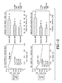
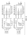
- FIGS. 9A and 9B are force-slip, slip ratio and wheel deceleration curves presented as example for a normal temperature tire and the ABS threshold tuning derivative therefrom. The conclusions on thresholding are indicated within each graph. From the graphs generated, ABS thresholds are identified and summarized in the table. Similar graphs 10A and 10B are shown as an example of tire curves for a cold tire. The results are summarized in table 30.
- a tire model suitable for use as the adaptive model (24 in FIG. 6 ) is based upon a conventional tire modeling brush model.
- the brush model is relatively simple, including two parameters to describe the shape of the force-slip curve, namely, the braking stiffness (C x ) and the maximal friction coefficient ( ⁇ peak ).
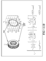
- FIG. 11B shows a schematic for tire 18 using the brush model and the expression solving for longitudinal force F x .
- FIG. 11A shows in graphic form the fit of the brush model-to-tire data.
- the brush model is relatively inaccurate at large slip ratios, i.e. it cannot characterize the shape factor since the brush model uses the simplifying assumption that static and sliding friction are equal.
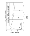
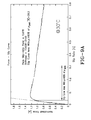
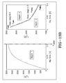
- FIG. 12A shows the importance of characterizing the shape factor (drop in the nonlinear region) for a normal temperature tire.
- the test speed is 60 mph, load of 1400 pounds and pressure: 34 psi.
- Stiffness (linear regression) 178695.
- FIG. 12B the same curve is shown for a cold tire.
- the cold tire has a much larger angle of drop after peak as compared to the normal tire.
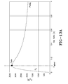
- FIG. 13A and enlarged regional representation of FIG. 13A in FIG. 13B a force slip curve is shown modified by splitting the curve into three separate regions: the region up until the optimal slip point (Region 1) and a region beyond the optimal slip point. The region beyond the optimal slip point is approximated by two line segments (e.g. region 2 and region 3).
- the regional expressions for longitudinal force are shown below:
- the drop for this modified model is captured by defining two physical terms, namely, the shape factor in the peak region ( ⁇ peak ) and the shape factor in the sliding region ( ⁇ sliding ).
- the modified brush model proposed constitutes a five parameter model with all parameters having a physical meaning.
- Model parameters: Cx, ⁇ peak , ⁇ sliding, ⁇ peak , ⁇ sliding refer respectively to braking stiffness, peak grip level, sliding grip level, angle of drop after peak and angle of drop in the sliding region.
- the model parameters accurately fit the test data even in the nonlinear (large slip) region.
- the regional dissection of the force slip curve in the modified brush model thus is capable of accurately providing the parameters identified above for the purpose of adjusting ABS thresholds.
- the subject system may be used to predict stopping distance of the vehicle in real time and, accordingly, be used to control a collision mitigation brake system (CMBS).
- CMBS collision mitigation brake system
- the same parameters determined from tire sensed information may be used to predict stopping distance through the use of a prediction model based on the tire state.
- FIGS. 15A and 15B The correlation of stopping distance to the tire longitudinal force curve features discussed previously is shown in FIGS. 15A and 15B .
- the correlation R to tire braking stiffness and peak grip 85 percent for a tire of Construction A.
- the correlation to tire braking stiffness, peak grip and shape factor (added parameter) is 96 percent.
- the inclusion of the shape factor parameter results in a significantly improved stopping distance prediction to ideal correlation.
- the linear regression model employed uses features extracted from the modified brush model to predict stopping distance as will be seen in FIG. 16 .
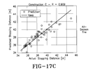
- FIGS. 17A , B, C the test results of the linear regression model for three different tire constructions are shown.
- the graphs of predicted stopping distance to actual distance show the model to perform at a high performance level.
- FIG. 18 shows a schematic for the use of the subject system and method 14 in vehicle control systems.
- the sensors and ID transponder devices affixed to the tire 18 provide dynamic tire-sensed information in real time. Such information includes tire make/type, inflation pressure, temperature and wear state.
- Wear state may be determined by affixing wear sensors to the tire tread region or estimated indirectly by analytical modeling.
- Tread depth may be estimated indirectly pursuant to a tire wear state estimation algorithm, such as that taught in US-A-2014/0366618 , hereby incorporated by reference in its entirety herein.
- the indirect tire wear state estimation algorithm is used to generate tread depth estimation indirectly; that is, without the use of tire mounted tread depth measuring sensors. As such, the difficulty of implementing and maintaining accurate tire-based sensor tread depth measurement is avoided.
- the indirect tire wear state estimation algorithm utilizes a hub acceleration signal which is accessible via the vehicle CAN Bus from vehicle based sensors.
- the hub acceleration signal is analyzed and an estimation is made as to the tread depth which, in turn, is reflective of the tire effective radius from which tread depth may be estimated.
- the tire sensed information is input into the online tire parameter identification process 24 discussed previously.
- the thresholds in the vehicle ABS 20 may be adjusted.
- the stopping distance prediction model 32 is also based on the tire state parameters identified from tire-sensed information. From stopping distance prediction, the CMBS may be adjusted in real time to provide a more accurate and robust control of vehicle safety.
- the subject invention provides a robust and tire-sensor based system and method of optimizing vehicle control systems such as ABS and CMBS.
- the system utilizes hardware in the form of multiple tire-based sensors mounted to one or all vehicle tires. From the tire based sensors, tire sensed information is obtained in real time and provides certain key tire measurements and identification data such as tire make/type, inflation pressure, temperature and wear state.
- An adaptive tire model processes the tire sensed information and generates an identification of tire parameters such as braking stiffness, optimal slip point, shape factor and peak grip. These tire parameters are then used to modify the thresholds in the vehicle ABS and/or the stopping distance used in the vehicle CMBS.
- Predictive knowledge of the ABS stopping distance for a given tire in any state is beneficial for safety systems, as prior knowledge of the tire's braking capability can be used to improve the robustness of the ABS controller and/or the CMBS system.
Landscapes
- Engineering & Computer Science (AREA)
- Mechanical Engineering (AREA)
- Transportation (AREA)
- Physics & Mathematics (AREA)
- Fluid Mechanics (AREA)
- Regulating Braking Force (AREA)
- Tires In General (AREA)
- Control Of Driving Devices And Active Controlling Of Vehicle (AREA)
Abstract
Description
- The invention relates generally to tire monitoring systems for collecting measured tire parameter data during vehicle operation and, more particularly, to a system and methods utilizing such tire sensor-based data in vehicle control systems.
- Vehicle-mounted tires during operation undergo considerable variation in tire properties such as braking stiffness, peak grip, and force-slip curve shape. Such variations may affect the performance of certain vehicle control systems such anti-lock braking systems. It is accordingly a desired objective to mitigate the effect of tire characteristic variability on such control systems and avoid degradation in performance.
- The invention relates to a system in accordance with
claim 1 and to methods in accordance withclaims 7 and 8 respectively. - Dependent claims refer to preferred embodiments of the invention.
- In a preferred daspect of the invention, a system and method of controlling a vehicle is provided in which multiple tire-based sensors are mounted to a vehicle tire to sense certain tire-derivative information. An adaptive tire model processes the tire-derivative information to continuously generate in real-time revisions to multiple tire-specific performance parameters. A vehicle control system(s), such as an anti-lock brake system and/or a collision mitigation braking system receives and applies in real-time the revisions to the tire-specific performance parameters to optimize the performance of the vehicle control system.
- In one aspect of the invention, the tire-specific performance parameters that may be used to adjust the vehicle control system are selected from the group tire braking stiffness, tire optimal slip point, tire shape factor and tire peak grip. The tire-derivative information may include tire make and type, tire inflation pressure, tire temperature and tire tread wear state.
- According to another preferred aspect, adjustment of the anti-lock brake system by revisions to the tire-specific performance parameters is made as an adjustment to the acceleration and deceleration thresholds for the vehicle anti-lock brake system.
- "ANN" or "Artificial Neural Network" is an adaptive tool for non-linear statistical data modeling that changes its structure based on external or internal information that flows through a network during a learning phase. ANN neural networks are non-linear statistical data modeling tools used to model complex relationships between inputs and outputs or to find patterns in data.
- "Axial" and "axially" means lines or directions that are parallel to the axis of rotation of the tire.
- "Circumferential" means lines or directions extending along the perimeter of the surface of the annular tread perpendicular to the axial direction.
- "Lateral" means an axial direction.
- "Piezoelectric Film Sensor" a device in the form of a film body that uses the piezoelectric effect actuated by a bending of the film body to measure pressure, acceleration, strain or force by converting them to an electrical charge.
- "Radial" and "radially" means directions radially toward or away from the axis of rotation of the tire.
- The invention will be described by way of example and with reference to the accompanying drawings in which:
-
FIG. 1 is a force-slip curve comparison graph between a normal tire and a cold tire. -
FIG. 2 are graphs showing the results of a sensitivity study on achievable braking performance between a normal tire and a cold tire. -
FIG. 3 are sensitivity study graphs showing tire construction dependency on achieving braking performance. -
FIG. 4 is another sensitivity study graph showing construction dependency on achieving braking performance. -
FIG. 5 is a sensitivity study graphs showing grip level vs. slip ratio and stopping distance comparison between a summer and an all-season tire. -
FIG. 6 is a schematic representation of the subject control system utilizing tire sensed information to optimize threshold setting within an ABS system. -
FIG. 7 is a graph showing the online tire parameter identification process. -
FIG. 8 is a graph showing experimental data, regression model fit and tire model fit in a tire force slip curve. -
FIG. 9A is a force slip curve graph illustrating tuning ABS thresholds for a normal tire. -
FIG. 9B are slip ratio and wheel deceleration curves illustrating the tuning of ABS thresholds for a normal temperature tire. -
FIG. 10A is a force slip curve graph illustrating the tuning of ABS thresholds for a cold tire. -
FIG. 10B are slip ratio and wheel deceleration curves illustrating the tuning of ABS thresholds for a cold temperature tire. -
FIG. 11A is a brush model fit graph showing tire data vs. brush model fit comparison. -
FIG. 11B is a schematic representation and mathematical representation of a tire model suitable for the adaptive model used in the subject control system and method. Also shown is the mathematical representation of the longitudinal force used in the model. -
FIG. 12A is a graph shown normalized force vs. slip ratio in a normal tire showing slip curve area with µ greater than 85 percent of peak. -
FIG. 12B is a graph similar toFIG. 12A but for a cold tire. -
FIG. 13A is a modified brush model force slip curve. -
FIG. 13B are enlargedRegions -
FIG. 14 is a force vs. slip ratio curve showing modified brush model fit. -
FIG. 15A is a graph of predicted stopping distance vs. actual stopping distance of a tire of construction A. -
FIG. 15B is a graph of predicted stopping distance vs. actual for a tire of Construction A including a "shape parameter" for improved fit. -
FIG. 16 is a force/slip ratio graph showing modified brush model fit in calculation of stopping distance. -
FIG. 17A through 17C are graphs comparing tire construction (summer vs. all-season) for constructions A, B, C, respectively. -
FIG. 18 is a system schematic representation showing use of tire sensed information in modifying ABS and CMBS vehicle control systems. - Referring to
FIG. 1 , a normalized force [µ] to slip ratio [λ] is shown comparing a "normal" tire attemperature 30°C with a cold tire at temperature of 0°C. As used herein, "normal" refers to a tire at a normal operating temperature of 30°C. As compared to the normal tire, the cold tire has a 40 to 45 percent higher braking stiffness; that is the optimal slip-ratio change point changes by approximately 50 percent. Also noted is a 10 to 15 percent lower peak grip level and a shape factor (drop in the nonlinear region) of the force slip curve changes significantly. In general, a tire is subjected to large variations in operating conditions such as temperature, inflation pressure and changing tread depth as the tire ages. The longitudinal force response of the tire changes significantly due to each of these operating conditions. Experimental data as shown herein indicates a considerable variation in tire properties such as braking stiffness, peak grip and force-slip curve shape due to change in tire temperature, wear state and tire construction (summer/winter/all-season). Variation in tire-force curves in turn have a significant effect on the braking performance (ABS efficiency/stopping distance) of the vehicle equipped with an anti-lock braking system (ABS) with fixed thresholds. Worn and cold tires can lead to a drop in ABS efficiency during braking due to a change in the optimum slip region which the ABS does not recognize. The subject control system employs tire identification (ID) in order to identify tire construction (summer/winter/all-season) with tire-attached tire pressure monitoring system (TPMS) devices to deliver tire temperature and pressure data in order to predict this change in the tire-force curve. As used herein, "tire sensed information" thus includes tire ID (used to ascertain tire construction type) and TPMS data (pressure and temperature) applied to predict the tire-force curve. Once the tire sensed information is known, the ABS can be adapted to recover the drop in efficiency through threshold optimization and thereby improve braking distance. - The graphs of
FIG. 2 show the results of a sensitivity study on achievable braking performance. Both a normal (temperature) tire and a cold tire were tested at 1400 pounds (1 pound = 0.4536 kg) loading, 34 psi (1 psi = 6895 Pa) inflation pressure and at a speed of 96.56 km/h (60 mph). The tire tested was a Goodyear 06-1G001PT98 E-1G0010A-6002 tire. The tire slip ratio curves for the normal tire showed a 4.04 m loss between actual ABS stopping distance and theoretical stopping distance, resulting in an ABS efficiency of 87 percent. For the cold tire (steeper drop in the curve), the loss was 7.35 m, resulting in an ABS efficiency of 79 percent. The simulation results thus show that the variation in the tire-force curves have a significant effect on the braking performance of the vehicle equipped with an ABS with fixed thresholds. - In
FIG. 3 , force-slip curves of a normal tire and a cold tire are shown. The two tires differ in linear stiffness, peak grip, optimal slip and slip curve area with µ> 85 percent of µpeak. The change noted in the optimal slip operation point indicates a deterioration in the performance of fixed thresholding rule based ABS algorithms. From this, it may be concluded that the reason for cold tire effect on braking is that a cold tire has a much higher braking stiffness and lower damping resulting in a faster response time, higher overshoot. A change in the shape factor of the force-slip curve and the limited flat area denoted atnumeral 10, causes a loss in the ABS efficiency. -
FIG. 4 is another force-slip curve comparison between two tires.Tire 1 being a Goodyear Summer Eagle F1 Asymmetric tire and Tire 2 a Goodyear All-Season Eagle tire. The dependency of ABS braking to tire construction will be appreciated from a comparison of the graphs of the two types of tires. Theflat regions 12 of the curves illustrate that construction of a tire has a dramatic effect on the force slip curve. By identifying the tire type from tire identification devices mounted to the tire, the subject system takes tire construction into account in adjusting the ABS thresholding in order to optimized braking performance. -
FIG. 5 illustrates further sensitivity study results comparing tire construction, summer vs. all-season. The steep drop in the summer tire curve translates into a 4.81 m loss in stopping distance, resulting in an ABS efficiency of 85 percent. The all-season tire, on the other hand, having a more gentle drop, creates a 4.10 m loss in actual to theoretical stopping distance and results in an 88 percent efficiency. ABS dependency on tire construction is thereby validated. - Referring to
FIGS. 6 and7 , the subject control system andmethod 14 is illustrated schematically. Tire-sensedinformation 16 is derived from devices affixed to avehicle tire 18. Such devices include one or more inflation sensors, one or more temperature sensors, a sensor from which tire tread wear may be ascertained and a transponder programmed to provide an identification of the tire as to tire make/type. This collective set of tire-attached devices provide tire-sensed information useful in adjusting the thresholding of the vehicle ABS system through ABS controllerthreshold optimization logic 22 to an optimized level. ABSmodule design parameters 20 include multiple acceleration/deceleration thresholds as identified at numeral 20 in addition to tire slip. By determining the actual real-time tire-slip curve for the tire based upon tire-sensed information, an optimal tire slip factor may be used, resulting in an optimization of the ABS thresholding. The system employs an online tireparameter identification process 24 by which tire parameters: braking stiffness, optimal slip point, shape factor and peak grip may be determined. Theprocess 24 represents a linear regression model that uses features extracted from a modified brush model in order to predict the stopping distance, which may further be utilized in a collision mitigation algorithm to adapt its critical distance (warning/braking distance) definitions with changing tire operating conditions, resulting in improved performance (reduced impact speed). The tire-sensed information thus enhances the performances of ABS controllers by optimizing the working thresholds with changing operating conditions of the tires. - The adaptive tire model employed in the online tire
parameter identification process 24 results in an online, real time slip-curve reflecting the actual condition of thetire 18 during operation. A representative sample of a resultant slip-curve 26 is shown inFIG. 7 . Grip level [µ] vs. slip ratio [λ] is graphed, showing a peak slip ratio of 0.0151, a peak grip level of 1.08, and a grip level at peak slip ratio of 0.83. Cx represents braking stiffness. - For current ABS systems, the operating thresholds are experimentally tuned during the vehicle set-up and in order to guarantee the controller robustness, the thresholds are determined as a result of an averaging procedure, taking into account changes in adherence conditions (dry, wet, snow, ice), variations in the vertical load distribution (vehicle loaded or unloaded), etc. The subject system and method enhances the performances of the ABS controller by optimizing the working thresholds.
- The importance of tire-sensed information is seen in the graph of
FIG. 8 , comparing experimental data, regression model fit and tire model fit in a tire force slip curve. Present ABS control strategy prevents wheels from locking up by increasing, decreasing and holding braking pressure ("pressure build up", "pressure release" and "pressure holding" phases). To determine which of these steps to execute, ABS electronic control unit (ECU) compares the peripheral acceleration and the estimated longitudinal slip of each individual wheel with fixed thresholds. Tire-related information is used by the subject system and method as follows: - (A) Peak slip ratio point used to determine the lower and upper slip and acceleration/ deceleration threshold,
- (B) Braking stiffness used to determine the ABS activation point and also tune the first cycle operation, and
- (C) Shape factor- affects the ABS efficiency (larger the drop implies the tire is less forgiving because of the limited "flat region" of the tire force curve resulting in a loss in the ABS efficiency).
- The curve of
FIG. 8 identifies the regions providing braking stiffness, peak grip, shape factor and optimal slip ratio information. -
FIGS. 9A and9B are force-slip, slip ratio and wheel deceleration curves presented as example for a normal temperature tire and the ABS threshold tuning derivative therefrom. The conclusions on thresholding are indicated within each graph. From the graphs generated, ABS thresholds are identified and summarized in the table. Similar graphs 10A and 10B are shown as an example of tire curves for a cold tire. The results are summarized in table 30. - A tire model suitable for use as the adaptive model (24 in
FIG. 6 ) is based upon a conventional tire modeling brush model. The brush model is relatively simple, including two parameters to describe the shape of the force-slip curve, namely, the braking stiffness (Cx) and the maximal friction coefficient (µpeak).FIG. 11B shows a schematic fortire 18 using the brush model and the expression solving for longitudinal force Fx.FIG. 11A shows in graphic form the fit of the brush model-to-tire data. As will be appreciated, the brush model is relatively inaccurate at large slip ratios, i.e. it cannot characterize the shape factor since the brush model uses the simplifying assumption that static and sliding friction are equal. -
FIG. 12A shows the importance of characterizing the shape factor (drop in the nonlinear region) for a normal temperature tire. The test speed is 60 mph, load of 1400 pounds and pressure: 34 psi. Stiffness (linear regression) = 178695. The slip curve area with µ > 85 percent of µpeak is shown as = 26.6. InFIG. 12B the same curve is shown for a cold tire. The value of µ > 85 percent of µpeak for a cold tire is = 5.9. The cold tire has a much larger angle of drop after peak as compared to the normal tire. - In order to overcome the limitations of the classic brush model, a modified brush model is preferred. In
FIG. 13A and enlarged regional representation ofFIG. 13A inFIG. 13B , a force slip curve is shown modified by splitting the curve into three separate regions: the region up until the optimal slip point (Region 1) and a region beyond the optimal slip point. The region beyond the optimal slip point is approximated by two line segments (e.g. region 2 and region 3). The regional expressions for longitudinal force are shown below: - Region 1:

for |λ| ≤ |λoptimal | - Region 2:

- Region 3:

for |0.4| < |λ| ≤ |1|
Where:- Fx: longitudinal force
- λ: slip ratio
- Cx: breaking stiffness
- µ peak: peak grip level
- λ optimal: slip ratio at point of peak grip
- α peak: shape factor in the peak region
- α sliding: shape factor in the sliding region
- Unlike the classical brush model which does not capture the drop/shape factor of the force slip curve, the drop for this modified model is captured by defining two physical terms, namely, the shape factor in the peak region (αpeak) and the shape factor in the sliding region (αsliding). Thus, the modified brush model proposed constitutes a five parameter model with all parameters having a physical meaning. Model parameters: Cx, µ peak, µ sliding, αpeak, αsliding refer respectively to braking stiffness, peak grip level, sliding grip level, angle of drop after peak and angle of drop in the sliding region.
- Referring to
FIG. 14 , it will be seen that the model parameters accurately fit the test data even in the nonlinear (large slip) region. The regional dissection of the force slip curve in the modified brush model thus is capable of accurately providing the parameters identified above for the purpose of adjusting ABS thresholds. - In addition to controlling thresholding of an ABS system within a vehicle, the subject system may be used to predict stopping distance of the vehicle in real time and, accordingly, be used to control a collision mitigation brake system (CMBS). The same parameters determined from tire sensed information may be used to predict stopping distance through the use of a prediction model based on the tire state. The correlation of stopping distance to the tire longitudinal force curve features discussed previously is shown in
FIGS. 15A and 15B . InFIG. 15A the correlation R to tire braking stiffness and peak grip is = 85 percent for a tire of Construction A. InFIG. 15B the correlation to tire braking stiffness, peak grip and shape factor (added parameter) is 96 percent. Thus, the inclusion of the shape factor parameter results in a significantly improved stopping distance prediction to ideal correlation. - The linear regression model employed uses features extracted from the modified brush model to predict stopping distance as will be seen in
FIG. 16 . InFIGS. 17A , B, C, the test results of the linear regression model for three different tire constructions are shown. The graphs of predicted stopping distance to actual distance show the model to perform at a high performance level. -
FIG. 18 shows a schematic for the use of the subject system andmethod 14 in vehicle control systems. The sensors and ID transponder devices affixed to thetire 18 provide dynamic tire-sensed information in real time. Such information includes tire make/type, inflation pressure, temperature and wear state. Wear state may be determined by affixing wear sensors to the tire tread region or estimated indirectly by analytical modeling. Tread depth may be estimated indirectly pursuant to a tire wear state estimation algorithm, such as that taught inUS-A-2014/0366618 , hereby incorporated by reference in its entirety herein. The indirect tire wear state estimation algorithm is used to generate tread depth estimation indirectly; that is, without the use of tire mounted tread depth measuring sensors. As such, the difficulty of implementing and maintaining accurate tire-based sensor tread depth measurement is avoided. The indirect tire wear state estimation algorithm utilizes a hub acceleration signal which is accessible via the vehicle CAN Bus from vehicle based sensors. The hub acceleration signal is analyzed and an estimation is made as to the tread depth which, in turn, is reflective of the tire effective radius from which tread depth may be estimated. - The tire sensed information is input into the online tire
parameter identification process 24 discussed previously. Upon identification of braking stiffness, optimal slip point, shape factor and peak grip, the thresholds in thevehicle ABS 20 may be adjusted. In addition, the stoppingdistance prediction model 32 is also based on the tire state parameters identified from tire-sensed information. From stopping distance prediction, the CMBS may be adjusted in real time to provide a more accurate and robust control of vehicle safety. - From the foregoing, it will be appreciated that the subject invention provides a robust and tire-sensor based system and method of optimizing vehicle control systems such as ABS and CMBS. The system utilizes hardware in the form of multiple tire-based sensors mounted to one or all vehicle tires. From the tire based sensors, tire sensed information is obtained in real time and provides certain key tire measurements and identification data such as tire make/type, inflation pressure, temperature and wear state. An adaptive tire model processes the tire sensed information and generates an identification of tire parameters such as braking stiffness, optimal slip point, shape factor and peak grip. These tire parameters are then used to modify the thresholds in the vehicle ABS and/or the stopping distance used in the vehicle CMBS. Predictive knowledge of the ABS stopping distance for a given tire in any state (temperature, pressure, wear state) is beneficial for safety systems, as prior knowledge of the tire's braking capability can be used to improve the robustness of the ABS controller and/or the CMBS system.
Claims (10)
- A vehicle control system comprising:a vehicle (14) having at least one supportive vehicle tire (18), the vehicle tire (18) having a tire cavity, a ground-engaging tread and a plurality of tire-specific parameters operably affecting at least one control system;a plurality of tire-based sensors mounted to the tire configured for operably sensing tire-specific or tire-derivative information (16);an adaptive tire model processor configured for operably receiving as inputs the tire-specific or tire-derivative information;wherein the adaptive tire model processor is configured to process the inputs through an adaptive model to substantially continuously generate revisions in real-time to the plurality of tire-specific parameters; and whereinthe at least one control system is configured to (i) operably modify at least one control system parameter in response to the revisions to the plurality of tire-specific or tire-derivative parameters; and/or to (ii) operably receive and apply in real-time the revisions to the tire-specific performance parameters in the control of the vehicle.
- The vehicle control system of claim 1, wherein the tire-specific or tire-derivative parameters comprise at least one parameter from the group: tire braking stiffness, tire optimal slip point, tire shape factor and tire peak grip.
- The vehicle control system of claim 1 or 2, wherein the tire-specific or tire-derivative information comprises information from the group: tire make and type, tire inflation pressure, tire temperature and tire tread wear state.
- The vehicle control system of claim 1, 2 or 3, wherein the at least one control system parameter is selected from the group: acceleration and deceleration thresholds for a vehicle anti-lock brake system and vehicle stopping distance.
- The vehicle control system of at least one of the previous claims, wherein the at least one control system comprises a vehicle anti-lock brake system being configured to receive and apply in real-time the revisions to the tire-specific or tire-derivative performance parameters to adjust a plurality of thresholding parameters.
- The vehicle control system of at least one of the previous claims, wherein the at least control system is a vehicle control system.
- A method of controlling a vehicle having at least one supportive vehicle tire using a vehicle control system in accordance with at least one of the previous claims.
- A method of controlling a vehicle (14) having at least one supportive vehicle tire (18), the vehicle tire (18) having a tire cavity and a ground-engaging tread and the tire having a plurality of tire-specific performance parameters from the group: tire braking stiffness, tire optimal slip point, tire shape factor and tire peak grip, the method comprising:mounting a plurality of tire-based sensors to the tire operably sensing tire-derivative information;processing the tire-derivative information to adaptively generate in real-time revisions to the plurality of tire-specific performance parameters;utilizing in real-time the revisions to the plurality of tire-specific performance parameters by at least one vehicle control system to control at least one vehicle performance parameter.
- The method of claim 8, wherein the tire-derivative information is selected from the group: tire make and type, tire inflation pressure, tire temperature and tire tread wear state.
- The method of claim 8 or 9, wherein the at least one vehicle performance parameter is selected from the group: acceleration and deceleration thresholds for a vehicle anti-lock brake system, stopping distance for a vehicle collision mitigation braking system.
Applications Claiming Priority (1)
| Application Number | Priority Date | Filing Date | Title |
|---|---|---|---|
| US14/537,177 US9963132B2 (en) | 2014-11-10 | 2014-11-10 | Tire sensor-based vehicle control system optimization and method |
Publications (2)
| Publication Number | Publication Date |
|---|---|
| EP3017971A1 true EP3017971A1 (en) | 2016-05-11 |
| EP3017971B1 EP3017971B1 (en) | 2018-09-19 |
Family
ID=54365152
Family Applications (1)
| Application Number | Title | Priority Date | Filing Date |
|---|---|---|---|
| EP15192575.7A Active EP3017971B1 (en) | 2014-11-10 | 2015-11-02 | Tire sensor-based vehicle control system optimization and method |
Country Status (2)
| Country | Link |
|---|---|
| US (1) | US9963132B2 (en) |
| EP (1) | EP3017971B1 (en) |
Cited By (2)
| Publication number | Priority date | Publication date | Assignee | Title |
|---|---|---|---|---|
| CN109910528A (en) * | 2017-12-12 | 2019-06-21 | 杨永全 | A kind of device monitoring large-sized truck wheel fault |
| CN113561714A (en) * | 2021-09-24 | 2021-10-29 | 深圳市信润富联数字科技有限公司 | Tire load monitoring method, device, equipment and storage medium |
Families Citing this family (9)
| Publication number | Priority date | Publication date | Assignee | Title |
|---|---|---|---|---|
| US9821611B2 (en) * | 2015-10-21 | 2017-11-21 | The Goodyear Tire & Rubber Company | Indirect tire wear state estimation system |
| ES2783374T3 (en) * | 2015-12-18 | 2020-09-17 | Nira Dynamics Ab | Tire stiffness estimate and road friction estimate |
| KR102485399B1 (en) * | 2017-09-27 | 2023-01-05 | 현대자동차주식회사 | Vehicle, and control method for the same |
| US10832567B2 (en) | 2018-10-19 | 2020-11-10 | Toyota Motor North America, Inc. | Systems and methods for generating composite real-time traffic images based on triggering events using data from vehicle borne sensors |
| US10987977B2 (en) | 2018-10-26 | 2021-04-27 | Toyota Motor North America, Inc. | Systems and methods for measuring tire wear using embedded image sensors |
| EP4261050A3 (en) | 2019-04-01 | 2024-01-03 | Bridgestone Americas Tire Operations, LLC | System and method for vehicle tire performance modeling and feedback |
| US11584342B2 (en) | 2019-10-28 | 2023-02-21 | Volkswagen Ag | Real-time performance handling virtual tire sensor |
| US11999348B2 (en) * | 2020-01-27 | 2024-06-04 | Tusimple, Inc. | Adaptive brake mode selection |
| CN114398806B (en) * | 2022-03-25 | 2022-07-19 | 北京蓝天航空科技股份有限公司 | Modeling method and device of generalized simulation model of flight simulator |
Citations (4)
| Publication number | Priority date | Publication date | Assignee | Title |
|---|---|---|---|---|
| EP2679411A2 (en) * | 2012-06-27 | 2014-01-01 | The Goodyear Tire & Rubber Company | Load estimation system and method for a vehicle tire |
| EP2777999A1 (en) * | 2013-03-12 | 2014-09-17 | The Goodyear Tire & Rubber Company | Dynamic tire slip angle estimation system and method |
| EP2777956A2 (en) * | 2013-03-12 | 2014-09-17 | The Goodyear Tire & Rubber Company | Tire suspension fusion system for estimation of tire deflection and tire load and method of estimating a tire load |
| US20140366618A1 (en) | 2013-06-14 | 2014-12-18 | Kanwar Bharat Singh | Tire wear state estimation system and method |
Family Cites Families (22)
| Publication number | Priority date | Publication date | Assignee | Title |
|---|---|---|---|---|
| US3525553A (en) * | 1968-09-30 | 1970-08-25 | Bendix Corp | Adaptive braking system responsive to tire-road surface conditions |
| US3640588A (en) * | 1970-03-03 | 1972-02-08 | Bendix Corp | Means for delaying effective control of vehicle braking by an adaptive braking system until certain wheel velocity and deceleration conditions have been satisfied |
| JPH0761340A (en) * | 1993-08-25 | 1995-03-07 | Nippon Denshi Kogyo Kk | Control point detecting method in abs device |
| DE19716586C1 (en) | 1997-04-21 | 1998-08-06 | Continental Ag | Tyre wear measuring method for moving vehicle |
| KR100383985B1 (en) * | 2000-12-26 | 2003-05-14 | 현대자동차주식회사 | Abs control system based on weared tires |
| WO2003031990A1 (en) | 2001-10-05 | 2003-04-17 | Continental Teves Ag & Co. Ohg | Device for combined detection of axle acceleration and wheel rotational speed, and method for determining pressure |
| WO2003053747A1 (en) | 2001-12-21 | 2003-07-03 | Kabushiki Kaisha Bridgestone | Method and apparatus for estimating road surface state and tire running state, abs and vehicle control using the same |
| DE10218781A1 (en) * | 2002-04-26 | 2003-11-13 | Tuev Automotive Gmbh | Pneumatic tire mountable on a rim, sensor network, revolution measuring unit and vehicle monitoring system |
| CN1860358B (en) | 2003-10-24 | 2010-04-28 | 倍耐力轮胎公司 | Method and system for determining a cornering angle of a tyre during the running of a vehicle |
| FR2866853B1 (en) * | 2004-02-27 | 2006-05-26 | Michelin Soc Tech | METHOD AND DEVICE FOR CONTROLLING SLIDING |
| JP4680532B2 (en) | 2004-06-02 | 2011-05-11 | 株式会社ブリヂストン | Method and apparatus for estimating dynamic state of tire |
| JP4787827B2 (en) * | 2004-06-30 | 2011-10-05 | ソシエテ ド テクノロジー ミシュラン | A system that estimates the maximum grip coefficient by measuring the stress of the tire tread. |
| CN100560390C (en) | 2004-09-29 | 2009-11-18 | 倍耐力轮胎股份公司 | In the vehicle operating process, determine the method and system of the angle of revolution of tire |
| JP5121445B2 (en) | 2005-03-24 | 2013-01-16 | 株式会社ブリヂストン | Estimation method of tire slip angle |
| JP5072463B2 (en) | 2007-07-11 | 2012-11-14 | 株式会社ブリヂストン | Tire wear detection method and tire wear detection device |
| DE102008056664A1 (en) | 2007-12-10 | 2009-06-18 | Continental Teves Ag & Co. Ohg | Method for indirect tire pressure monitoring and tire pressure monitoring system |
| US8483976B2 (en) | 2008-06-25 | 2013-07-09 | Kabushiki Kaisha Bridgestone | Method for estimating tire wear and apparatus for estimating tire wear |
| IT1393072B1 (en) | 2008-10-24 | 2012-04-11 | Pirelli | METHOD AND SYSTEM FOR REPORTING A CONDITION OF AQUAPLANO OF A TIRE ASSEMBLED ON A VEHICLE |
| DE112009005342B4 (en) | 2009-11-04 | 2019-06-27 | Nira Dynamics Ab | Classification of the road surface |
| DE102010050634A1 (en) | 2010-11-05 | 2012-05-10 | Wabco Gmbh | A control system for a vehicle control system and method for determining tire conditions of vehicle tires |
| FR2978736B1 (en) * | 2011-08-01 | 2013-09-27 | Airbus Operations Sas | DEVICE AND METHOD FOR DETERMINING A TRACK STATE, AIRCRAFT COMPRISING SUCH A DEVICE AND A PILOTAGE ASSISTANCE SYSTEM UTILIZING THE TRACK STATE |
| WO2013114388A1 (en) * | 2011-12-23 | 2013-08-08 | Muthukumar Prasad | Smart active tyre pressure optimising system |
-
2014
- 2014-11-10 US US14/537,177 patent/US9963132B2/en active Active
-
2015
- 2015-11-02 EP EP15192575.7A patent/EP3017971B1/en active Active
Patent Citations (4)
| Publication number | Priority date | Publication date | Assignee | Title |
|---|---|---|---|---|
| EP2679411A2 (en) * | 2012-06-27 | 2014-01-01 | The Goodyear Tire & Rubber Company | Load estimation system and method for a vehicle tire |
| EP2777999A1 (en) * | 2013-03-12 | 2014-09-17 | The Goodyear Tire & Rubber Company | Dynamic tire slip angle estimation system and method |
| EP2777956A2 (en) * | 2013-03-12 | 2014-09-17 | The Goodyear Tire & Rubber Company | Tire suspension fusion system for estimation of tire deflection and tire load and method of estimating a tire load |
| US20140366618A1 (en) | 2013-06-14 | 2014-12-18 | Kanwar Bharat Singh | Tire wear state estimation system and method |
Cited By (3)
| Publication number | Priority date | Publication date | Assignee | Title |
|---|---|---|---|---|
| CN109910528A (en) * | 2017-12-12 | 2019-06-21 | 杨永全 | A kind of device monitoring large-sized truck wheel fault |
| CN113561714A (en) * | 2021-09-24 | 2021-10-29 | 深圳市信润富联数字科技有限公司 | Tire load monitoring method, device, equipment and storage medium |
| CN113561714B (en) * | 2021-09-24 | 2022-01-07 | 深圳市信润富联数字科技有限公司 | Tire load monitoring method, device, equipment and storage medium |
Also Published As
| Publication number | Publication date |
|---|---|
| EP3017971B1 (en) | 2018-09-19 |
| US20160129894A1 (en) | 2016-05-12 |
| US9963132B2 (en) | 2018-05-08 |
Similar Documents
| Publication | Publication Date | Title |
|---|---|---|
| EP3017971B1 (en) | Tire sensor-based vehicle control system optimization and method | |
| EP3028910B1 (en) | Slip ratio point optimization system and method for vehicle control | |
| EP3421267B1 (en) | Tire wear state estimation system and method | |
| EP3023761B1 (en) | Tire cornering stiffness estimation system and method | |
| EP2837510B1 (en) | Torsional mode tire wear state estimation system and method | |
| EP2813378B1 (en) | Tire wear state estimation system and method | |
| EP2927065B1 (en) | Road surface friction and surface type estimation system and method | |
| EP2927066B1 (en) | Model-based longitudinal stiffness estimation system and method | |
| EP3318422B1 (en) | Indirect tire wear state prediction system and method | |
| US9120356B2 (en) | Load estimation system and method for a vehicle tire | |
| CN103660811B (en) | Tire sidewall load estimation system and method | |
| EP2865572A1 (en) | Road friction estimation system and method | |
| EP3028880B1 (en) | Tire lift-off propensity predictive system and method | |
| Singh et al. | Enhancement of collision mitigation braking system performance through real-time estimation of tire-road friction coefficient by means of smart tires | |
| US9963146B2 (en) | Tire lift-off propensity predictive system and method | |
| EP3159189B1 (en) | Indirect tire wear state estimation system and method of tire state estimation through wheel speed signal feature extraction | |
| JP2021092431A (en) | Vehicle mass estimation device | |
| Tanelli et al. | Friction-curve peak detection by wheel-deceleration measurements | |
| Singh et al. | Development of a smart tire system and its use in improving the performance of a collision mitigation braking system | |
| Singh | Developing enabling technologies for intelligent tires | |
| JP5464580B2 (en) | Tire resonance frequency decompression sensitivity estimation apparatus and method, and tire resonance frequency decompression sensitivity estimation program |
Legal Events
| Date | Code | Title | Description |
|---|---|---|---|
| PUAI | Public reference made under article 153(3) epc to a published international application that has entered the european phase |
Free format text: ORIGINAL CODE: 0009012 |
|
| AK | Designated contracting states |
Kind code of ref document: A1 Designated state(s): AL AT BE BG CH CY CZ DE DK EE ES FI FR GB GR HR HU IE IS IT LI LT LU LV MC MK MT NL NO PL PT RO RS SE SI SK SM TR |
|
| AX | Request for extension of the european patent |
Extension state: BA ME |
|
| 17P | Request for examination filed |
Effective date: 20161111 |
|
| RBV | Designated contracting states (corrected) |
Designated state(s): AL AT BE BG CH CY CZ DE DK EE ES FI FR GB GR HR HU IE IS IT LI LT LU LV MC MK MT NL NO PL PT RO RS SE SI SK SM TR |
|
| 17Q | First examination report despatched |
Effective date: 20170727 |
|
| GRAP | Despatch of communication of intention to grant a patent |
Free format text: ORIGINAL CODE: EPIDOSNIGR1 |
|
| INTG | Intention to grant announced |
Effective date: 20180410 |
|
| GRAS | Grant fee paid |
Free format text: ORIGINAL CODE: EPIDOSNIGR3 |
|
| GRAA | (expected) grant |
Free format text: ORIGINAL CODE: 0009210 |
|
| AK | Designated contracting states |
Kind code of ref document: B1 Designated state(s): AL AT BE BG CH CY CZ DE DK EE ES FI FR GB GR HR HU IE IS IT LI LT LU LV MC MK MT NL NO PL PT RO RS SE SI SK SM TR |
|
| REG | Reference to a national code |
Ref country code: GB Ref legal event code: FG4D |
|
| REG | Reference to a national code |
Ref country code: CH Ref legal event code: EP |
|
| REG | Reference to a national code |
Ref country code: FR Ref legal event code: PLFP Year of fee payment: 4 |
|
| REG | Reference to a national code |
Ref country code: AT Ref legal event code: REF Ref document number: 1042822 Country of ref document: AT Kind code of ref document: T Effective date: 20181015 |
|
| REG | Reference to a national code |
Ref country code: IE Ref legal event code: FG4D |
|
| REG | Reference to a national code |
Ref country code: DE Ref legal event code: R096 Ref document number: 602015016553 Country of ref document: DE |
|
| REG | Reference to a national code |
Ref country code: NL Ref legal event code: MP Effective date: 20180919 |
|
| PG25 | Lapsed in a contracting state [announced via postgrant information from national office to epo] |
Ref country code: BG Free format text: LAPSE BECAUSE OF FAILURE TO SUBMIT A TRANSLATION OF THE DESCRIPTION OR TO PAY THE FEE WITHIN THE PRESCRIBED TIME-LIMIT Effective date: 20181219 Ref country code: LT Free format text: LAPSE BECAUSE OF FAILURE TO SUBMIT A TRANSLATION OF THE DESCRIPTION OR TO PAY THE FEE WITHIN THE PRESCRIBED TIME-LIMIT Effective date: 20180919 Ref country code: GR Free format text: LAPSE BECAUSE OF FAILURE TO SUBMIT A TRANSLATION OF THE DESCRIPTION OR TO PAY THE FEE WITHIN THE PRESCRIBED TIME-LIMIT Effective date: 20181220 Ref country code: SE Free format text: LAPSE BECAUSE OF FAILURE TO SUBMIT A TRANSLATION OF THE DESCRIPTION OR TO PAY THE FEE WITHIN THE PRESCRIBED TIME-LIMIT Effective date: 20180919 Ref country code: NO Free format text: LAPSE BECAUSE OF FAILURE TO SUBMIT A TRANSLATION OF THE DESCRIPTION OR TO PAY THE FEE WITHIN THE PRESCRIBED TIME-LIMIT Effective date: 20181219 Ref country code: RS Free format text: LAPSE BECAUSE OF FAILURE TO SUBMIT A TRANSLATION OF THE DESCRIPTION OR TO PAY THE FEE WITHIN THE PRESCRIBED TIME-LIMIT Effective date: 20180919 Ref country code: FI Free format text: LAPSE BECAUSE OF FAILURE TO SUBMIT A TRANSLATION OF THE DESCRIPTION OR TO PAY THE FEE WITHIN THE PRESCRIBED TIME-LIMIT Effective date: 20180919 |
|
| REG | Reference to a national code |
Ref country code: LT Ref legal event code: MG4D |
|
| PG25 | Lapsed in a contracting state [announced via postgrant information from national office to epo] |
Ref country code: HR Free format text: LAPSE BECAUSE OF FAILURE TO SUBMIT A TRANSLATION OF THE DESCRIPTION OR TO PAY THE FEE WITHIN THE PRESCRIBED TIME-LIMIT Effective date: 20180919 Ref country code: AL Free format text: LAPSE BECAUSE OF FAILURE TO SUBMIT A TRANSLATION OF THE DESCRIPTION OR TO PAY THE FEE WITHIN THE PRESCRIBED TIME-LIMIT Effective date: 20180919 Ref country code: LV Free format text: LAPSE BECAUSE OF FAILURE TO SUBMIT A TRANSLATION OF THE DESCRIPTION OR TO PAY THE FEE WITHIN THE PRESCRIBED TIME-LIMIT Effective date: 20180919 |
|
| REG | Reference to a national code |
Ref country code: AT Ref legal event code: MK05 Ref document number: 1042822 Country of ref document: AT Kind code of ref document: T Effective date: 20180919 |
|
| PG25 | Lapsed in a contracting state [announced via postgrant information from national office to epo] |
Ref country code: CZ Free format text: LAPSE BECAUSE OF FAILURE TO SUBMIT A TRANSLATION OF THE DESCRIPTION OR TO PAY THE FEE WITHIN THE PRESCRIBED TIME-LIMIT Effective date: 20180919 Ref country code: RO Free format text: LAPSE BECAUSE OF FAILURE TO SUBMIT A TRANSLATION OF THE DESCRIPTION OR TO PAY THE FEE WITHIN THE PRESCRIBED TIME-LIMIT Effective date: 20180919 Ref country code: IT Free format text: LAPSE BECAUSE OF FAILURE TO SUBMIT A TRANSLATION OF THE DESCRIPTION OR TO PAY THE FEE WITHIN THE PRESCRIBED TIME-LIMIT Effective date: 20180919 Ref country code: PL Free format text: LAPSE BECAUSE OF FAILURE TO SUBMIT A TRANSLATION OF THE DESCRIPTION OR TO PAY THE FEE WITHIN THE PRESCRIBED TIME-LIMIT Effective date: 20180919 Ref country code: NL Free format text: LAPSE BECAUSE OF FAILURE TO SUBMIT A TRANSLATION OF THE DESCRIPTION OR TO PAY THE FEE WITHIN THE PRESCRIBED TIME-LIMIT Effective date: 20180919 Ref country code: EE Free format text: LAPSE BECAUSE OF FAILURE TO SUBMIT A TRANSLATION OF THE DESCRIPTION OR TO PAY THE FEE WITHIN THE PRESCRIBED TIME-LIMIT Effective date: 20180919 Ref country code: AT Free format text: LAPSE BECAUSE OF FAILURE TO SUBMIT A TRANSLATION OF THE DESCRIPTION OR TO PAY THE FEE WITHIN THE PRESCRIBED TIME-LIMIT Effective date: 20180919 Ref country code: ES Free format text: LAPSE BECAUSE OF FAILURE TO SUBMIT A TRANSLATION OF THE DESCRIPTION OR TO PAY THE FEE WITHIN THE PRESCRIBED TIME-LIMIT Effective date: 20180919 Ref country code: IS Free format text: LAPSE BECAUSE OF FAILURE TO SUBMIT A TRANSLATION OF THE DESCRIPTION OR TO PAY THE FEE WITHIN THE PRESCRIBED TIME-LIMIT Effective date: 20190119 |
|
| PG25 | Lapsed in a contracting state [announced via postgrant information from national office to epo] |
Ref country code: PT Free format text: LAPSE BECAUSE OF FAILURE TO SUBMIT A TRANSLATION OF THE DESCRIPTION OR TO PAY THE FEE WITHIN THE PRESCRIBED TIME-LIMIT Effective date: 20190119 Ref country code: SM Free format text: LAPSE BECAUSE OF FAILURE TO SUBMIT A TRANSLATION OF THE DESCRIPTION OR TO PAY THE FEE WITHIN THE PRESCRIBED TIME-LIMIT Effective date: 20180919 Ref country code: SK Free format text: LAPSE BECAUSE OF FAILURE TO SUBMIT A TRANSLATION OF THE DESCRIPTION OR TO PAY THE FEE WITHIN THE PRESCRIBED TIME-LIMIT Effective date: 20180919 |
|
| REG | Reference to a national code |
Ref country code: DE Ref legal event code: R097 Ref document number: 602015016553 Country of ref document: DE |
|
| REG | Reference to a national code |
Ref country code: CH Ref legal event code: PL |
|
| PLBE | No opposition filed within time limit |
Free format text: ORIGINAL CODE: 0009261 |
|
| STAA | Information on the status of an ep patent application or granted ep patent |
Free format text: STATUS: NO OPPOSITION FILED WITHIN TIME LIMIT |
|
| PG25 | Lapsed in a contracting state [announced via postgrant information from national office to epo] |
Ref country code: MC Free format text: LAPSE BECAUSE OF FAILURE TO SUBMIT A TRANSLATION OF THE DESCRIPTION OR TO PAY THE FEE WITHIN THE PRESCRIBED TIME-LIMIT Effective date: 20180919 Ref country code: LU Free format text: LAPSE BECAUSE OF NON-PAYMENT OF DUE FEES Effective date: 20181102 Ref country code: DK Free format text: LAPSE BECAUSE OF FAILURE TO SUBMIT A TRANSLATION OF THE DESCRIPTION OR TO PAY THE FEE WITHIN THE PRESCRIBED TIME-LIMIT Effective date: 20180919 |
|
| REG | Reference to a national code |
Ref country code: BE Ref legal event code: MM Effective date: 20181130 |
|
| REG | Reference to a national code |
Ref country code: IE Ref legal event code: MM4A |
|
| 26N | No opposition filed |
Effective date: 20190620 |
|
| PG25 | Lapsed in a contracting state [announced via postgrant information from national office to epo] |
Ref country code: CH Free format text: LAPSE BECAUSE OF NON-PAYMENT OF DUE FEES Effective date: 20181130 Ref country code: LI Free format text: LAPSE BECAUSE OF NON-PAYMENT OF DUE FEES Effective date: 20181130 |
|
| PG25 | Lapsed in a contracting state [announced via postgrant information from national office to epo] |
Ref country code: IE Free format text: LAPSE BECAUSE OF NON-PAYMENT OF DUE FEES Effective date: 20181102 Ref country code: SI Free format text: LAPSE BECAUSE OF FAILURE TO SUBMIT A TRANSLATION OF THE DESCRIPTION OR TO PAY THE FEE WITHIN THE PRESCRIBED TIME-LIMIT Effective date: 20180919 |
|
| PG25 | Lapsed in a contracting state [announced via postgrant information from national office to epo] |
Ref country code: BE Free format text: LAPSE BECAUSE OF NON-PAYMENT OF DUE FEES Effective date: 20181130 |
|
| PG25 | Lapsed in a contracting state [announced via postgrant information from national office to epo] |
Ref country code: MT Free format text: LAPSE BECAUSE OF NON-PAYMENT OF DUE FEES Effective date: 20181102 |
|
| PG25 | Lapsed in a contracting state [announced via postgrant information from national office to epo] |
Ref country code: TR Free format text: LAPSE BECAUSE OF FAILURE TO SUBMIT A TRANSLATION OF THE DESCRIPTION OR TO PAY THE FEE WITHIN THE PRESCRIBED TIME-LIMIT Effective date: 20180919 |
|
| PG25 | Lapsed in a contracting state [announced via postgrant information from national office to epo] |
Ref country code: HU Free format text: LAPSE BECAUSE OF FAILURE TO SUBMIT A TRANSLATION OF THE DESCRIPTION OR TO PAY THE FEE WITHIN THE PRESCRIBED TIME-LIMIT; INVALID AB INITIO Effective date: 20151102 Ref country code: CY Free format text: LAPSE BECAUSE OF FAILURE TO SUBMIT A TRANSLATION OF THE DESCRIPTION OR TO PAY THE FEE WITHIN THE PRESCRIBED TIME-LIMIT Effective date: 20180919 Ref country code: MK Free format text: LAPSE BECAUSE OF NON-PAYMENT OF DUE FEES Effective date: 20180919 |
|
| PGFP | Annual fee paid to national office [announced via postgrant information from national office to epo] |
Ref country code: GB Payment date: 20210922 Year of fee payment: 7 |
|
| GBPC | Gb: european patent ceased through non-payment of renewal fee |
Effective date: 20221102 |
|
| PG25 | Lapsed in a contracting state [announced via postgrant information from national office to epo] |
Ref country code: GB Free format text: LAPSE BECAUSE OF NON-PAYMENT OF DUE FEES Effective date: 20221102 |
|
| PGFP | Annual fee paid to national office [announced via postgrant information from national office to epo] |
Ref country code: FR Payment date: 20230911 Year of fee payment: 9 |
|
| PGFP | Annual fee paid to national office [announced via postgrant information from national office to epo] |
Ref country code: DE Payment date: 20230906 Year of fee payment: 9 |