EP3028880B1 - Tire lift-off propensity predictive system and method - Google Patents
Tire lift-off propensity predictive system and method Download PDFInfo
- Publication number
- EP3028880B1 EP3028880B1 EP15196859.1A EP15196859A EP3028880B1 EP 3028880 B1 EP3028880 B1 EP 3028880B1 EP 15196859 A EP15196859 A EP 15196859A EP 3028880 B1 EP3028880 B1 EP 3028880B1
- Authority
- EP
- European Patent Office
- Prior art keywords
- tire
- vehicle
- lift
- propensity
- specific
- Prior art date
- Legal status (The legal status is an assumption and is not a legal conclusion. Google has not performed a legal analysis and makes no representation as to the accuracy of the status listed.)
- Active
Links
- 238000000034 method Methods 0.000 title claims description 18
- 230000002596 correlated effect Effects 0.000 claims description 3
- 238000004519 manufacturing process Methods 0.000 claims 1
- 238000010276 construction Methods 0.000 description 6
- 230000001133 acceleration Effects 0.000 description 5
- 238000005259 measurement Methods 0.000 description 3
- 230000009467 reduction Effects 0.000 description 3
- 230000003044 adaptive effect Effects 0.000 description 2
- 239000000853 adhesive Substances 0.000 description 2
- 230000001070 adhesive effect Effects 0.000 description 2
- 238000013528 artificial neural network Methods 0.000 description 2
- 238000010586 diagram Methods 0.000 description 2
- 230000006870 function Effects 0.000 description 2
- 238000012544 monitoring process Methods 0.000 description 2
- 238000012545 processing Methods 0.000 description 2
- 238000005452 bending Methods 0.000 description 1
- 230000005540 biological transmission Effects 0.000 description 1
- 230000008859 change Effects 0.000 description 1
- 230000008878 coupling Effects 0.000 description 1
- 238000010168 coupling process Methods 0.000 description 1
- 238000005859 coupling reaction Methods 0.000 description 1
- 230000001419 dependent effect Effects 0.000 description 1
- 230000000694 effects Effects 0.000 description 1
- 239000007788 liquid Substances 0.000 description 1
- 239000000463 material Substances 0.000 description 1
- 230000000246 remedial effect Effects 0.000 description 1
- 230000004044 response Effects 0.000 description 1
- 238000012360 testing method Methods 0.000 description 1
Images

Classifications
-
- B—PERFORMING OPERATIONS; TRANSPORTING
- B60—VEHICLES IN GENERAL
- B60C—VEHICLE TYRES; TYRE INFLATION; TYRE CHANGING; CONNECTING VALVES TO INFLATABLE ELASTIC BODIES IN GENERAL; DEVICES OR ARRANGEMENTS RELATED TO TYRES
- B60C23/00—Devices for measuring, signalling, controlling, or distributing tyre pressure or temperature, specially adapted for mounting on vehicles; Arrangement of tyre inflating devices on vehicles, e.g. of pumps or of tanks; Tyre cooling arrangements
- B60C23/02—Signalling devices actuated by tyre pressure
- B60C23/04—Signalling devices actuated by tyre pressure mounted on the wheel or tyre
-
- G—PHYSICS
- G01—MEASURING; TESTING
- G01M—TESTING STATIC OR DYNAMIC BALANCE OF MACHINES OR STRUCTURES; TESTING OF STRUCTURES OR APPARATUS, NOT OTHERWISE PROVIDED FOR
- G01M17/00—Testing of vehicles
- G01M17/007—Wheeled or endless-tracked vehicles
- G01M17/02—Tyres
-
- B—PERFORMING OPERATIONS; TRANSPORTING
- B60—VEHICLES IN GENERAL
- B60C—VEHICLE TYRES; TYRE INFLATION; TYRE CHANGING; CONNECTING VALVES TO INFLATABLE ELASTIC BODIES IN GENERAL; DEVICES OR ARRANGEMENTS RELATED TO TYRES
- B60C11/00—Tyre tread bands; Tread patterns; Anti-skid inserts
- B60C11/24—Wear-indicating arrangements
- B60C11/243—Tread wear sensors, e.g. electronic sensors
-
- B—PERFORMING OPERATIONS; TRANSPORTING
- B60—VEHICLES IN GENERAL
- B60C—VEHICLE TYRES; TYRE INFLATION; TYRE CHANGING; CONNECTING VALVES TO INFLATABLE ELASTIC BODIES IN GENERAL; DEVICES OR ARRANGEMENTS RELATED TO TYRES
- B60C19/00—Tyre parts or constructions not otherwise provided for
-
- B—PERFORMING OPERATIONS; TRANSPORTING
- B60—VEHICLES IN GENERAL
- B60C—VEHICLE TYRES; TYRE INFLATION; TYRE CHANGING; CONNECTING VALVES TO INFLATABLE ELASTIC BODIES IN GENERAL; DEVICES OR ARRANGEMENTS RELATED TO TYRES
- B60C23/00—Devices for measuring, signalling, controlling, or distributing tyre pressure or temperature, specially adapted for mounting on vehicles; Arrangement of tyre inflating devices on vehicles, e.g. of pumps or of tanks; Tyre cooling arrangements
- B60C23/02—Signalling devices actuated by tyre pressure
- B60C23/04—Signalling devices actuated by tyre pressure mounted on the wheel or tyre
- B60C23/0486—Signalling devices actuated by tyre pressure mounted on the wheel or tyre comprising additional sensors in the wheel or tyre mounted monitoring device, e.g. movement sensors, microphones or earth magnetic field sensors
- B60C23/0488—Movement sensor, e.g. for sensing angular speed, acceleration or centripetal force
-
- B—PERFORMING OPERATIONS; TRANSPORTING
- B60—VEHICLES IN GENERAL
- B60C—VEHICLE TYRES; TYRE INFLATION; TYRE CHANGING; CONNECTING VALVES TO INFLATABLE ELASTIC BODIES IN GENERAL; DEVICES OR ARRANGEMENTS RELATED TO TYRES
- B60C23/00—Devices for measuring, signalling, controlling, or distributing tyre pressure or temperature, specially adapted for mounting on vehicles; Arrangement of tyre inflating devices on vehicles, e.g. of pumps or of tanks; Tyre cooling arrangements
- B60C23/06—Signalling devices actuated by deformation of the tyre, e.g. tyre mounted deformation sensors or indirect determination of tyre deformation based on wheel speed, wheel-centre to ground distance or inclination of wheel axle
- B60C23/061—Signalling devices actuated by deformation of the tyre, e.g. tyre mounted deformation sensors or indirect determination of tyre deformation based on wheel speed, wheel-centre to ground distance or inclination of wheel axle by monitoring wheel speed
-
- B—PERFORMING OPERATIONS; TRANSPORTING
- B60—VEHICLES IN GENERAL
- B60W—CONJOINT CONTROL OF VEHICLE SUB-UNITS OF DIFFERENT TYPE OR DIFFERENT FUNCTION; CONTROL SYSTEMS SPECIALLY ADAPTED FOR HYBRID VEHICLES; ROAD VEHICLE DRIVE CONTROL SYSTEMS FOR PURPOSES NOT RELATED TO THE CONTROL OF A PARTICULAR SUB-UNIT
- B60W30/00—Purposes of road vehicle drive control systems not related to the control of a particular sub-unit, e.g. of systems using conjoint control of vehicle sub-units, or advanced driver assistance systems for ensuring comfort, stability and safety or drive control systems for propelling or retarding the vehicle
- B60W30/02—Control of vehicle driving stability
- B60W30/04—Control of vehicle driving stability related to roll-over prevention
-
- B—PERFORMING OPERATIONS; TRANSPORTING
- B60—VEHICLES IN GENERAL
- B60W—CONJOINT CONTROL OF VEHICLE SUB-UNITS OF DIFFERENT TYPE OR DIFFERENT FUNCTION; CONTROL SYSTEMS SPECIALLY ADAPTED FOR HYBRID VEHICLES; ROAD VEHICLE DRIVE CONTROL SYSTEMS FOR PURPOSES NOT RELATED TO THE CONTROL OF A PARTICULAR SUB-UNIT
- B60W50/00—Details of control systems for road vehicle drive control not related to the control of a particular sub-unit, e.g. process diagnostic or vehicle driver interfaces
- B60W50/08—Interaction between the driver and the control system
- B60W50/14—Means for informing the driver, warning the driver or prompting a driver intervention
-
- B—PERFORMING OPERATIONS; TRANSPORTING
- B60—VEHICLES IN GENERAL
- B60C—VEHICLE TYRES; TYRE INFLATION; TYRE CHANGING; CONNECTING VALVES TO INFLATABLE ELASTIC BODIES IN GENERAL; DEVICES OR ARRANGEMENTS RELATED TO TYRES
- B60C19/00—Tyre parts or constructions not otherwise provided for
- B60C2019/004—Tyre sensors other than for detecting tyre pressure
-
- B—PERFORMING OPERATIONS; TRANSPORTING
- B60—VEHICLES IN GENERAL
- B60W—CONJOINT CONTROL OF VEHICLE SUB-UNITS OF DIFFERENT TYPE OR DIFFERENT FUNCTION; CONTROL SYSTEMS SPECIALLY ADAPTED FOR HYBRID VEHICLES; ROAD VEHICLE DRIVE CONTROL SYSTEMS FOR PURPOSES NOT RELATED TO THE CONTROL OF A PARTICULAR SUB-UNIT
- B60W2520/00—Input parameters relating to overall vehicle dynamics
- B60W2520/10—Longitudinal speed
Definitions
- the invention relates generally to tire monitoring systems for collecting measured tire parameter data during vehicle operation and, more particularly, to systems utilizing such tire sensor-based data in vehicle control systems.
- a vehicle tire may encounter a propensity to lift-off from a road surface.
- Lift-off may be caused by the tire hydroplaning during operation of the vehicle.
- Hydroplaning can occur when the contact patch created by a vehicle tire and a road surface is reduced in area due to the presence of moisture.
- a reduction in travel speed of the vehicle is generally recommended.
- DE 10 2010 007008 A1 , DE 10 2007 010780 A1 , DE 10 2006 043505 A1 and DE 10 2006 033951 A1 each describe a lift-off propensity predictive system and method wherein the estimating means/steps of the system and method are in response to tire specific parameters such as tire pressure and vehicle speed.
- the invention relates to a system in accordance with claim 1 and to a method in accordance with claim 8.
- a system and method for predicting tire lift-off propensity includes a vehicle tire-affixed tire-identification device for providing a tire-specific identification, multiple tire-affixed sensors mounted to the tire measuring tire-specific parameters and generating tire-specific parameter information, one or more vehicle-affixed sensor(s) mounted to the vehicle to measure vehicle speed and a lift-off propensity estimator generating a lift-off propensity for the vehicle tire a database containing experimentally-derived, tire-ID specific, lift-off propensities correlated to measured tire-specific parameter information and measured vehicle speeds.
- the tire-specific parameter information is one or more parameters from the group: a load estimation for the vehicle tire, air pressure within a cavity of the vehicle tire and a wear estimation for a tread region of the vehicle tire.
- the lift-off propensity predictive system calculates the load estimation based upon a vehicle-based hub accelerometer signal.
- the lift-off propensity predictive system in another preferred aspect of the invention continuously updates the lift-off propensity of the vehicle tire during movement of the vehicle and uses the updated lift-off propensity in one or more control system(s) of the vehicle such as vehicle speed control.
- ANN Artificial Neural Network
- ANN neural networks are non-linear statistical data modeling tools used to model complex relationships between inputs and outputs or to find patterns in data.
- Axial and “axially” means lines or directions that are parallel to the axis of rotation of the tire.
- “Circumferential” means lines or directions extending along the perimeter of the surface of the annular tread perpendicular to the axial direction.
- Dugoff Model is an empirical tire model providing analytical relations for the longitudinal and lateral forces as functions of the slip angle and slip ratio. It accounts for the coupling between the side and longitudinal forces.
- “Lateral” means an axial direction.
- Piezoelectric Film Sensor a device in the form of a film body that uses the piezoelectric effect actuated by a bending of the film body to measure pressure, acceleration, strain or force by converting them to an electrical charge.
- Ring and radially means directions radially toward or away from the axis of rotation of the tire.
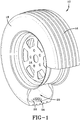
- the tire 12 is one of several tires supporting a vehicle such as, but not limited to, a passenger automobile.
- the tire 12 is of conventional construction and is mounted to a wheel 14.
- the tire 12 has a tread region 16, sidewalls 18, a pressurized air cavity 20 defined by an inner liner 22.
- a sensor module, prefereably referred herein as tire pressure monitoring sensor (TPMS) module or “device”, 24 is mounted to the tire inner liner by suitable means such as adhesive.
- the TPMS sensor module 24 includes a pressure sensor for measuring the air pressure within cavity 20, temperature of the tire (if desired) and a tire identification transponder programmed to provide a tire-specific identification.
- the module 24 is further equipped with telemetric transmission capability by which the pressure, temperature and identification information can be sent wirelessly to a remote receiver (not shown) for processing.
- the module sensors are commercially available and packaged and may be affixed to the inner liner through the use of commercially available adhesive.
- the tire 12 makes a road-engaging contact patch as the tire rotates along a road surface.
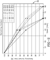
- the "contact patch" area is a function of tire inflation pressure, tire loading, vehicle speed, tire construction and the wear state of the tire.
- the greater the inflation pressure the less contact area is created. The faster a vehicle, and hence the tire, travels, the less contact area is established by the tire against the road surface.
- the contact area of the tire is inversely proportional to the lift-off tendency of the tire. That is, the greater the contact area of the tire is against the road surface, the lower the lift-off tendency of the tire from the road surface. "Lift-off tendency" is most commonly experienced and exacerbated when a material or liquid (hydroplaning) is present between the tire and the road surface resulting in a reduction of contact area between the tire the road surface. From the test result graphs of FIG. 2 , it will be appreciated that the inflation pressure and tire wear state dependencies are useful for predicting tire lift-off conditions. The loading conditions will also affect the curves of FIG. 2 since the contact patch area changes with tire load. Tire ID Information reveals the particular tire-specific construction of the tire.
- tire-specific identification makes the curves and algorithms of FIG. 2 tire-specific. "Remaining contact area" curves will change dramatically for a stiff tire vs. a less stiff tire.
- tire-specific remaining contact area curves may be generated from tire-specific measurement of tire inflation pressure, load and vehicle speed.
- FIG. 3 an Implementation Flow Diagram of the subject system and method for estimating lift-off propensity is shown.
- a vehicle 10 is supported by multiple tires 12 configured and described above in reference to FIG. 1 .
- vehicle-based sensors such as vehicle-mounted accelerometers
- vehicle-based information is conveyed to a tire lift-off propensity estimator 42 via the vehicle CAN bus signals 28.
- Vehicle-based information includes vehicle speed 31 and hub acceleration 30.
- the CAN signal hub acceleration 30 is input into an indirect wear estimation method 40 that estimates the wear state of the tires.
- Tread depth or wear state may be determined directly from tire tread-mounted sensors or from an adaptive indirect tread wear such as the wear estimation method found in US-A-2014/0366618 , hereby incorporated by reference in its entirety herein.
- the wear estimation method of the co-pending application does so "indirectly", that is, without the use of tire mounted tread depth measuring sensors. As such, the difficulty of implementing and maintaining accurate tire-based sensor tread depth measurement is avoided.
- the indirect tire wear state estimation algorithm utilizes the hub acceleration signal 30 which is accessible via the vehicle CAN bus 28 from vehicle based sensors. The hub acceleration signal is analyzed and an estimation is made as to tread depth or wear.
- the tread depth used may be the percentage tread wear left or a quantitative value of tread wear depth left on the tire.
- tire ID 38, tire cavity inflation pressure 36, and tire load measurement 32 are derived and transmitted for processing to the tire lift-off propensity estimator 42.
- the load 32 is estimated from a load estimation method 34 incorporating a dynamic tire load estimator configured as presented in US-A-2014/0278040 , hereby incorporated herein in its entirety.
- the tire-based inputs of tire ID, pressure and load constitute tire-based information inputs into the tire lift-off propensity prediction estimator or algorithm 42.
- the estimator 42 includes a tire-specific database experimentally derived and based upon a tire ID. From the tire ID, the type of tire construction is known. The tire ID obtained from the TPMS module 24 allows the estimator to identify the tire and recognize the specific type of construction.
- the reference database utilizes the pressure 36, load estimation 32, vehicle speed 31 and indirect wear estimation 40 to determine the contact patch for the tire. From the contact patch area tire lift-off propensity is concluded by the estimator 42. Should the tire lift-off propensity exceed a preset threshold limit, a warning 44 is generated to the driver of the vehicle and/or the vehicle controller.
- the driver may take remedial action by reducing the vehicle speed
- the controller can redistribute the force to a tire with a larger contact patch area (higher road holding capacity) and thereby mitigate the propensity for tire lift-off.
- the controller can manage the distribution of force between tires and thereby reduce the potential for lift-off.
- a vehicle tire-affixed tire-identification device within the module 24 provides a tire-specific identification.
- Multiple tire-affixed sensors within the module 24 are mounted to the tire to measure and provide certain tire-specific parameters (pressure, load, wear state).
- Tire-specific parameter information (wear state, pressure, load) are inputs with vehicle-based sensor derived vehicle speed into the estimator 42.
- the tire lift-off propensity estimator 42 fits the inputs into a database that is based upon tire ID recognition.
- the estimator 42 generates a lift-off propensity for the vehicle tire based on the recognized tire ID. Lift-off propensities are thereby concluded from a correlation of the specific tire-based parameter information and measured vehicle speeds with the recognized Tire ID.
- the tire-specific parameter information combines a load estimation for the vehicle tire, air pressure within a cavity of the vehicle tire and a wear estimation for a tread region of the vehicle tire as inputs into the estimator 42.
- the lift-off propensity predictive system continuously updates the lift-off propensities of the vehicle tires during movement of the vehicle and uses the updated lift-off propensities in one or more control system(s) of the vehicle such as driver initiated vehicle speed control and/or vehicle controller-driven force distribution between vehicle tires.
Description
- The invention relates generally to tire monitoring systems for collecting measured tire parameter data during vehicle operation and, more particularly, to systems utilizing such tire sensor-based data in vehicle control systems.
- Under certain conditions, a vehicle tire may encounter a propensity to lift-off from a road surface. Lift-off may be caused by the tire hydroplaning during operation of the vehicle. Hydroplaning can occur when the contact patch created by a vehicle tire and a road surface is reduced in area due to the presence of moisture. In order to reduce hydroplaning, a reduction in travel speed of the vehicle is generally recommended. There is a need for a durable and robust system and method for advising a vehicle operator when conditions for tire lift-off exist so that a reduction in vehicle speed may be effected.
-
DE 10 2010 007008 A1 ,DE 10 2007 010780 A1 ,DE 10 2006 043505 A1 andDE 10 2006 033951 A1 , according to the preamble of device claim 1, each describe a lift-off propensity predictive system and method wherein the estimating means/steps of the system and method are in response to tire specific parameters such as tire pressure and vehicle speed. - The invention relates to a system in accordance with claim 1 and to a method in accordance with claim 8.
- Dependent claims refer to preferred embodiments of the invention.
- In a preferred aspect of the invention, a system and method for predicting tire lift-off propensity includes a vehicle tire-affixed tire-identification device for providing a tire-specific identification, multiple tire-affixed sensors mounted to the tire measuring tire-specific parameters and generating tire-specific parameter information, one or more vehicle-affixed sensor(s) mounted to the vehicle to measure vehicle speed and a lift-off propensity estimator generating a lift-off propensity for the vehicle tire a database containing experimentally-derived, tire-ID specific, lift-off propensities correlated to measured tire-specific parameter information and measured vehicle speeds.
- In another preferred aspect of the invention, the tire-specific parameter information is one or more parameters from the group: a load estimation for the vehicle tire, air pressure within a cavity of the vehicle tire and a wear estimation for a tread region of the vehicle tire.
- The lift-off propensity predictive system, in a further preferred aspect of the invention, calculates the load estimation based upon a vehicle-based hub accelerometer signal.
- The lift-off propensity predictive system in another preferred aspect of the invention continuously updates the lift-off propensity of the vehicle tire during movement of the vehicle and uses the updated lift-off propensity in one or more control system(s) of the vehicle such as vehicle speed control.
- "ANN" or "Artificial Neural Network" is an adaptive tool for non-linear statistical data modeling that changes its structure based on external or internal information that flows through a network during a learning phase. ANN neural networks are non-linear statistical data modeling tools used to model complex relationships between inputs and outputs or to find patterns in data.
- "Axial" and "axially" means lines or directions that are parallel to the axis of rotation of the tire.
- "Circumferential" means lines or directions extending along the perimeter of the surface of the annular tread perpendicular to the axial direction.
- "Dugoff Model" is an empirical tire model providing analytical relations for the longitudinal and lateral forces as functions of the slip angle and slip ratio. It accounts for the coupling between the side and longitudinal forces.
- "Lateral" means an axial direction.
- "Piezoelectric Film Sensor" a device in the form of a film body that uses the piezoelectric effect actuated by a bending of the film body to measure pressure, acceleration, strain or force by converting them to an electrical charge.
- "Radial" and "radially" means directions radially toward or away from the axis of rotation of the tire.
- The invention will be described by way of example and with reference to the accompanying drawings in which:
-
FIG. 1 is perspective view of a vehicle tire partially sectioned to show attachment of a TPMS sensor module. -
FIG. 2 is a graph of tire remaining contact (percent) vs. speed (mph) for a tire at varying tire pressures and varying wear states. -
FIG. 3 is an implementation flow diagram of the subject system for predicting tire lift-off propensity. - Referring to
FIG. 1 , a vehicleexemplary tire 12 is shown. Thetire 12 is one of several tires supporting a vehicle such as, but not limited to, a passenger automobile. Thetire 12 is of conventional construction and is mounted to awheel 14. Thetire 12 has atread region 16,sidewalls 18, a pressurizedair cavity 20 defined by aninner liner 22. A sensor module, prefereably referred herein as tire pressure monitoring sensor (TPMS) module or "device", 24 is mounted to the tire inner liner by suitable means such as adhesive. TheTPMS sensor module 24 includes a pressure sensor for measuring the air pressure withincavity 20, temperature of the tire (if desired) and a tire identification transponder programmed to provide a tire-specific identification. Themodule 24 is further equipped with telemetric transmission capability by which the pressure, temperature and identification information can be sent wirelessly to a remote receiver (not shown) for processing. The module sensors are commercially available and packaged and may be affixed to the inner liner through the use of commercially available adhesive. - With reference to
FIG. 2 , agraph 26 of remaining contact area (percent) vs. speed of the vehicle (mph) is shown (1 mph = 1.604 km). Thetire 12 makes a road-engaging contact patch as the tire rotates along a road surface. The "contact patch" area is a function of tire inflation pressure, tire loading, vehicle speed, tire construction and the wear state of the tire. The graphs inFIG. 2 demonstrates that variation in tire inflation pressures (33, 37, 41 psi (1 psi = 6895 Pa)) and the wear state (worn vs. new) of the tire tread has a direct influence on the contact area of the tire as it contacts a road surface at speeds ranging from 0 to 80 mph. In general, the greater the inflation pressure, the less contact area is created. The faster a vehicle, and hence the tire, travels, the less contact area is established by the tire against the road surface. - The contact area of the tire is inversely proportional to the lift-off tendency of the tire. That is, the greater the contact area of the tire is against the road surface, the lower the lift-off tendency of the tire from the road surface. "Lift-off tendency" is most commonly experienced and exacerbated when a material or liquid (hydroplaning) is present between the tire and the road surface resulting in a reduction of contact area between the tire the road surface. From the test result graphs of
FIG. 2 , it will be appreciated that the inflation pressure and tire wear state dependencies are useful for predicting tire lift-off conditions. The loading conditions will also affect the curves ofFIG. 2 since the contact patch area changes with tire load. Tire ID Information reveals the particular tire-specific construction of the tire. The tire-specific identification, in turn, makes the curves and algorithms ofFIG. 2 tire-specific. "Remaining contact area" curves will change dramatically for a stiff tire vs. a less stiff tire. By identifying the tire and its construction parameters, tire-specific remaining contact area curves may be generated from tire-specific measurement of tire inflation pressure, load and vehicle speed. - In
FIG. 3 , an Implementation Flow Diagram of the subject system and method for estimating lift-off propensity is shown. Avehicle 10 is supported bymultiple tires 12 configured and described above in reference toFIG. 1 . From vehicle-based sensors such as vehicle-mounted accelerometers, vehicle-based information is conveyed to a tire lift-offpropensity estimator 42 via the vehicleCAN bus signals 28. Vehicle-based information includesvehicle speed 31 andhub acceleration 30. The CANsignal hub acceleration 30 is input into an indirectwear estimation method 40 that estimates the wear state of the tires. - Tread depth or wear state may be determined directly from tire tread-mounted sensors or from an adaptive indirect tread wear such as the wear estimation method found in
US-A-2014/0366618 , hereby incorporated by reference in its entirety herein. The wear estimation method of the co-pending application does so "indirectly", that is, without the use of tire mounted tread depth measuring sensors. As such, the difficulty of implementing and maintaining accurate tire-based sensor tread depth measurement is avoided. The indirect tire wear state estimation algorithm utilizes thehub acceleration signal 30 which is accessible via thevehicle CAN bus 28 from vehicle based sensors. The hub acceleration signal is analyzed and an estimation is made as to tread depth or wear. The tread depth used may be the percentage tread wear left or a quantitative value of tread wear depth left on the tire. - From tire-based sensors packaged within the
TPMS module 24,tire ID 38, tirecavity inflation pressure 36, andtire load measurement 32 are derived and transmitted for processing to the tire lift-offpropensity estimator 42. Theload 32 is estimated from aload estimation method 34 incorporating a dynamic tire load estimator configured as presented inUS-A-2014/0278040 , hereby incorporated herein in its entirety. The tire-based inputs of tire ID, pressure and load constitute tire-based information inputs into the tire lift-off propensity prediction estimator oralgorithm 42. - The
estimator 42 includes a tire-specific database experimentally derived and based upon a tire ID. From the tire ID, the type of tire construction is known. The tire ID obtained from theTPMS module 24 allows the estimator to identify the tire and recognize the specific type of construction. The reference database utilizes thepressure 36,load estimation 32,vehicle speed 31 andindirect wear estimation 40 to determine the contact patch for the tire. From the contact patch area tire lift-off propensity is concluded by theestimator 42. Should the tire lift-off propensity exceed a preset threshold limit, awarning 44 is generated to the driver of the vehicle and/or the vehicle controller. The driver, being warned of a high lift-off propensity, may take remedial action by reducing the vehicle speed The controller can redistribute the force to a tire with a larger contact patch area (higher road holding capacity) and thereby mitigate the propensity for tire lift-off. By calculating lift-off propensity for each tire, the controller can manage the distribution of force between tires and thereby reduce the potential for lift-off. - From the foregoing, it will be appreciated that the subject system and method achieves a tire lift-off propensity prediction which is both accurate and tire-specific. A vehicle tire-affixed tire-identification device within the
module 24 provides a tire-specific identification. Multiple tire-affixed sensors within themodule 24 are mounted to the tire to measure and provide certain tire-specific parameters (pressure, load, wear state). Tire-specific parameter information (wear state, pressure, load) are inputs with vehicle-based sensor derived vehicle speed into theestimator 42. The tire lift-offpropensity estimator 42 fits the inputs into a database that is based upon tire ID recognition. Theestimator 42 generates a lift-off propensity for the vehicle tire based on the recognized tire ID. Lift-off propensities are thereby concluded from a correlation of the specific tire-based parameter information and measured vehicle speeds with the recognized Tire ID. - The tire-specific parameter information combines a load estimation for the vehicle tire, air pressure within a cavity of the vehicle tire and a wear estimation for a tread region of the vehicle tire as inputs into the
estimator 42. The lift-off propensity predictive system continuously updates the lift-off propensities of the vehicle tires during movement of the vehicle and uses the updated lift-off propensities in one or more control system(s) of the vehicle such as driver initiated vehicle speed control and/or vehicle controller-driven force distribution between vehicle tires.
Claims (13)
- A lift-off propensity predictive system comprising:a vehicle (10) supported by at least one vehicle tire (12) mounted to a hub, the vehicle tire having a tire cavity (20) and a ground-engaging tread (16), and the tire (12) having a plurality of tire-specific measureable parameters;a tire-affixed tire-identification device (24) for providing a tire-specific identification;a plurality of tire-affixed sensors mounted to the tire (12) for operably measuring the tire-specific parameters and generating tire-specific parameter information;at least one vehicle-affixed sensor mounted to the vehicle for operably measuring vehicle speed (31);characterized in that the system comprises a lift-off propensity estimator (42) for operably generating a lift-off propensity for the one vehicle tire (12) from a database containing experimentally-derived, tire-ID specific, lift-off propensities correlated to measured tire-specific parameter information and measured vehicle speed.
- The system according to claim 1, wherein the tire-specific parameter information is selected from the group:a load estimation for the one vehicle tire (12);air pressure within a cavity (20) of the one vehicle tire (12); anda wear estimation for a tread region of the one vehicle tire.
- The system according to claim 2, wherein the load estimation is configured for operably calculating a load estimation based upon a vehicle-based hub accelerometer signal.
- The system of claim 1, 2 or 3, wherein the system is configured to substantially continuously update the lift-off propensity during an movement of the vehicle (10) and, optionally, wherein the system is configured to operably utilize the updated lift-off propensity in at least one control system of the vehicle (10).
- The system of claim 4, wherein the at least one control system of the vehicle comprises vehicle speed control.
- The system according to at least one of the previous claims, wherein the system is configured to utilize a load estimation input for operably calculating a load estimation based upon a vehicle-based hub accelerometer signal.
- The system according to at least one of the previous claims, wherein the system is configured for continuously updating the estimated lift-off propensity during travel of the vehicle.
- A method of making a lift-off propensity estimation, the method comprising:mounting at least one vehicle tire (12) to a vehicle (10), the vehicle tire (12) having a tire cavity (20) and a ground-engaging tread (16), and the tire (12) having a plurality of tire-specific measureable parameters;affixing to the one vehicle tire (12) a tire identification device providing a tire-specific identification;affixing at least one vehicle-affixed sensor to the vehicle operably measuring vehicle speed (31);mounting a plurality of tire-affixed sensors to the tire operably measuring the tire-specific parameters to generate tire-specific parameter information;inputting the tire-specific parameter information and the tire-specific identification and the vehicle speed into a lift-off propensity estimator (42);generating a lift-off propensity estimation from the lift-off propensity estimator (42) using a database containing experimentally-derived, tire-ID specific, lift-off propensities correlated to measured tire-specific parameter information and measured vehicle speeds.
- The method according to claim 8, further comprising including within the tire-specific parameter information a load estimation for the one vehicle tire, air pressure within a cavity (20) of the one vehicle tire (12) and a wear estimation for a tread region of the one vehicle tire (12).
- The method according to claim 8 or 9, further comprising utilizing a vehicle-based accelerometer signal to generate the load estimation for the one vehicle tire.
- The method according to claim 8, 9 or 10, further comprising substantially continuously updating the lift-off estimation during an operation of the vehicle to adjust for changes in the tire-specific information.
- The method according to at least one of the previous claims, further comprising using the updated lift-off estimation in at least one control system of the vehicle.
- The method according to claim 12, wherein the at least one control system comprises a vehicle speed control system.
Applications Claiming Priority (1)
| Application Number | Priority Date | Filing Date | Title |
|---|---|---|---|
| US14/558,783 US20160161373A1 (en) | 2014-12-03 | 2014-12-03 | Tire lift-off propensity predictive system and method |
Publications (2)
| Publication Number | Publication Date |
|---|---|
| EP3028880A1 EP3028880A1 (en) | 2016-06-08 |
| EP3028880B1 true EP3028880B1 (en) | 2018-01-31 |
Family
ID=54707672
Family Applications (1)
| Application Number | Title | Priority Date | Filing Date |
|---|---|---|---|
| EP15196859.1A Active EP3028880B1 (en) | 2014-12-03 | 2015-11-27 | Tire lift-off propensity predictive system and method |
Country Status (2)
| Country | Link |
|---|---|
| US (1) | US20160161373A1 (en) |
| EP (1) | EP3028880B1 (en) |
Families Citing this family (6)
| Publication number | Priority date | Publication date | Assignee | Title |
|---|---|---|---|---|
| US9821611B2 (en) * | 2015-10-21 | 2017-11-21 | The Goodyear Tire & Rubber Company | Indirect tire wear state estimation system |
| CN107600074B (en) * | 2017-07-14 | 2019-11-22 | 北汽福田汽车股份有限公司 | Vehicle speed measurement method and device |
| IT201800005600A1 (en) * | 2018-05-22 | 2019-11-22 | SYSTEM AND METHOD FOR MANAGING DATA RELEVANT TO A WHEEL SERVICE | |
| US11131076B2 (en) * | 2018-09-05 | 2021-09-28 | Deere & Company | Controlling a work machine based on in-rubber tire/track sensor |
| CN111332077B (en) * | 2019-08-20 | 2021-11-30 | 厦门乐创智联科技有限公司 | Tire monitoring and managing system and using method thereof |
| US20220314965A1 (en) * | 2021-03-31 | 2022-10-06 | Honda Motor Co., Ltd. | Systems and methods for stabilizing a vehicle on two wheels |
Family Cites Families (8)
| Publication number | Priority date | Publication date | Assignee | Title |
|---|---|---|---|---|
| US9443358B2 (en) * | 1995-06-07 | 2016-09-13 | Automotive Vehicular Sciences LLC | Vehicle software upgrade techniques |
| DE102007010780B4 (en) * | 2006-03-02 | 2016-01-28 | Continental Teves Ag & Co. Ohg | Tire module with piezoelectric transducer |
| DE102006043505A1 (en) * | 2006-05-22 | 2007-11-29 | Continental Teves Ag & Co. Ohg | Tire module and method for detecting wheel and / or tire condition sizes |
| DE102006033951A1 (en) * | 2006-07-22 | 2007-10-25 | Audi Ag | Device for determining wheel load of tire of motor vehicle has pressure sensor by which at least tire inflation pressure can be determined regardless of tire rotation speed |
| DE102010007008B4 (en) * | 2010-02-05 | 2017-08-10 | Huf Hülsbeck & Fürst Gmbh & Co. Kg | Method for monitoring the load of vehicle tires |
| DE102012217901B3 (en) * | 2012-10-01 | 2014-05-28 | Continental Automotive Gmbh | Method, controller and system for determining a tread depth of a tread of a tire |
| US9222854B2 (en) | 2013-03-12 | 2015-12-29 | The Goodyear Tire & Rubber Company | Vehicle dynamic load estimation system and method |
| US9050864B2 (en) | 2013-06-14 | 2015-06-09 | The Goodyear Tire & Rubber Company | Tire wear state estimation system and method |
-
2014
- 2014-12-03 US US14/558,783 patent/US20160161373A1/en not_active Abandoned
-
2015
- 2015-11-27 EP EP15196859.1A patent/EP3028880B1/en active Active
Non-Patent Citations (1)
| Title |
|---|
| None * |
Also Published As
| Publication number | Publication date |
|---|---|
| US20160161373A1 (en) | 2016-06-09 |
| EP3028880A1 (en) | 2016-06-08 |
Similar Documents
| Publication | Publication Date | Title |
|---|---|---|
| EP3028880B1 (en) | Tire lift-off propensity predictive system and method | |
| EP3028910B1 (en) | Slip ratio point optimization system and method for vehicle control | |
| EP3020578B1 (en) | Tire wear compensated load estimation system and method | |
| EP3378679B1 (en) | Model based tire wear estimation system and method | |
| EP3023761B1 (en) | Tire cornering stiffness estimation system and method | |
| EP3421267B1 (en) | Tire wear state estimation system and method | |
| US9963146B2 (en) | Tire lift-off propensity predictive system and method | |
| US9995654B2 (en) | Tire and vehicle sensor-based vehicle state estimation system and method | |
| US9874496B2 (en) | Tire suspension fusion system for estimation of tire deflection and tire load | |
| EP3017971B1 (en) | Tire sensor-based vehicle control system optimization and method | |
| EP3318422B1 (en) | Indirect tire wear state prediction system and method | |
| EP3785943B1 (en) | Tire wear state estimation system and method employing footprint length | |
| EP2927074B1 (en) | Tire based system and method for adapting the calculation of temperature-sensitive tire characteristics | |
| US10048170B2 (en) | Vehicle loading condition detection system and method | |
| CN111433054B (en) | Method and system for monitoring parameters related to a tyre during the running of a vehicle | |
| EP3838628B1 (en) | Method of estimating tire conditions | |
| CN111615479B (en) | Tire system | |
| EP3785944B1 (en) | Tire wear state estimation system and method employing footprint shape factor | |
| US11644386B2 (en) | Tire wear state estimation system and method | |
| EP4140838A1 (en) | Road condition monitoring system and method | |
| CN115723765A (en) | Road condition monitoring system |
Legal Events
| Date | Code | Title | Description |
|---|---|---|---|
| PUAI | Public reference made under article 153(3) epc to a published international application that has entered the european phase |
Free format text: ORIGINAL CODE: 0009012 |
|
| AK | Designated contracting states |
Kind code of ref document: A1 Designated state(s): AL AT BE BG CH CY CZ DE DK EE ES FI FR GB GR HR HU IE IS IT LI LT LU LV MC MK MT NL NO PL PT RO RS SE SI SK SM TR |
|
| AX | Request for extension of the european patent |
Extension state: BA ME |
|
| 17P | Request for examination filed |
Effective date: 20161208 |
|
| RBV | Designated contracting states (corrected) |
Designated state(s): AL AT BE BG CH CY CZ DE DK EE ES FI FR GB GR HR HU IE IS IT LI LT LU LV MC MK MT NL NO PL PT RO RS SE SI SK SM TR |
|
| GRAP | Despatch of communication of intention to grant a patent |
Free format text: ORIGINAL CODE: EPIDOSNIGR1 |
|
| RIC1 | Information provided on ipc code assigned before grant |
Ipc: B60W 30/04 20060101ALI20170724BHEP Ipc: B60C 23/04 20060101AFI20170724BHEP Ipc: B60C 23/06 20060101ALI20170724BHEP |
|
| INTG | Intention to grant announced |
Effective date: 20170817 |
|
| GRAS | Grant fee paid |
Free format text: ORIGINAL CODE: EPIDOSNIGR3 |
|
| GRAA | (expected) grant |
Free format text: ORIGINAL CODE: 0009210 |
|
| AK | Designated contracting states |
Kind code of ref document: B1 Designated state(s): AL AT BE BG CH CY CZ DE DK EE ES FI FR GB GR HR HU IE IS IT LI LT LU LV MC MK MT NL NO PL PT RO RS SE SI SK SM TR |
|
| REG | Reference to a national code |
Ref country code: GB Ref legal event code: FG4D Ref country code: CH Ref legal event code: EP |
|
| REG | Reference to a national code |
Ref country code: AT Ref legal event code: REF Ref document number: 967007 Country of ref document: AT Kind code of ref document: T Effective date: 20180215 |
|
| REG | Reference to a national code |
Ref country code: IE Ref legal event code: FG4D |
|
| REG | Reference to a national code |
Ref country code: DE Ref legal event code: R096 Ref document number: 602015007749 Country of ref document: DE |
|
| REG | Reference to a national code |
Ref country code: NL Ref legal event code: MP Effective date: 20180131 |
|
| REG | Reference to a national code |
Ref country code: LT Ref legal event code: MG4D |
|
| REG | Reference to a national code |
Ref country code: AT Ref legal event code: MK05 Ref document number: 967007 Country of ref document: AT Kind code of ref document: T Effective date: 20180131 |
|
| PG25 | Lapsed in a contracting state [announced via postgrant information from national office to epo] |
Ref country code: NO Free format text: LAPSE BECAUSE OF FAILURE TO SUBMIT A TRANSLATION OF THE DESCRIPTION OR TO PAY THE FEE WITHIN THE PRESCRIBED TIME-LIMIT Effective date: 20180430 Ref country code: FI Free format text: LAPSE BECAUSE OF FAILURE TO SUBMIT A TRANSLATION OF THE DESCRIPTION OR TO PAY THE FEE WITHIN THE PRESCRIBED TIME-LIMIT Effective date: 20180131 Ref country code: NL Free format text: LAPSE BECAUSE OF FAILURE TO SUBMIT A TRANSLATION OF THE DESCRIPTION OR TO PAY THE FEE WITHIN THE PRESCRIBED TIME-LIMIT Effective date: 20180131 Ref country code: HR Free format text: LAPSE BECAUSE OF FAILURE TO SUBMIT A TRANSLATION OF THE DESCRIPTION OR TO PAY THE FEE WITHIN THE PRESCRIBED TIME-LIMIT Effective date: 20180131 Ref country code: ES Free format text: LAPSE BECAUSE OF FAILURE TO SUBMIT A TRANSLATION OF THE DESCRIPTION OR TO PAY THE FEE WITHIN THE PRESCRIBED TIME-LIMIT Effective date: 20180131 Ref country code: LT Free format text: LAPSE BECAUSE OF FAILURE TO SUBMIT A TRANSLATION OF THE DESCRIPTION OR TO PAY THE FEE WITHIN THE PRESCRIBED TIME-LIMIT Effective date: 20180131 |
|
| PG25 | Lapsed in a contracting state [announced via postgrant information from national office to epo] |
Ref country code: IS Free format text: LAPSE BECAUSE OF FAILURE TO SUBMIT A TRANSLATION OF THE DESCRIPTION OR TO PAY THE FEE WITHIN THE PRESCRIBED TIME-LIMIT Effective date: 20180531 Ref country code: BG Free format text: LAPSE BECAUSE OF FAILURE TO SUBMIT A TRANSLATION OF THE DESCRIPTION OR TO PAY THE FEE WITHIN THE PRESCRIBED TIME-LIMIT Effective date: 20180430 Ref country code: RS Free format text: LAPSE BECAUSE OF FAILURE TO SUBMIT A TRANSLATION OF THE DESCRIPTION OR TO PAY THE FEE WITHIN THE PRESCRIBED TIME-LIMIT Effective date: 20180131 Ref country code: LV Free format text: LAPSE BECAUSE OF FAILURE TO SUBMIT A TRANSLATION OF THE DESCRIPTION OR TO PAY THE FEE WITHIN THE PRESCRIBED TIME-LIMIT Effective date: 20180131 Ref country code: SE Free format text: LAPSE BECAUSE OF FAILURE TO SUBMIT A TRANSLATION OF THE DESCRIPTION OR TO PAY THE FEE WITHIN THE PRESCRIBED TIME-LIMIT Effective date: 20180131 Ref country code: AT Free format text: LAPSE BECAUSE OF FAILURE TO SUBMIT A TRANSLATION OF THE DESCRIPTION OR TO PAY THE FEE WITHIN THE PRESCRIBED TIME-LIMIT Effective date: 20180131 Ref country code: PL Free format text: LAPSE BECAUSE OF FAILURE TO SUBMIT A TRANSLATION OF THE DESCRIPTION OR TO PAY THE FEE WITHIN THE PRESCRIBED TIME-LIMIT Effective date: 20180131 Ref country code: GR Free format text: LAPSE BECAUSE OF FAILURE TO SUBMIT A TRANSLATION OF THE DESCRIPTION OR TO PAY THE FEE WITHIN THE PRESCRIBED TIME-LIMIT Effective date: 20180501 |
|
| REG | Reference to a national code |
Ref country code: FR Ref legal event code: PLFP Year of fee payment: 4 |
|
| PG25 | Lapsed in a contracting state [announced via postgrant information from national office to epo] |
Ref country code: IT Free format text: LAPSE BECAUSE OF FAILURE TO SUBMIT A TRANSLATION OF THE DESCRIPTION OR TO PAY THE FEE WITHIN THE PRESCRIBED TIME-LIMIT Effective date: 20180131 Ref country code: RO Free format text: LAPSE BECAUSE OF FAILURE TO SUBMIT A TRANSLATION OF THE DESCRIPTION OR TO PAY THE FEE WITHIN THE PRESCRIBED TIME-LIMIT Effective date: 20180131 Ref country code: EE Free format text: LAPSE BECAUSE OF FAILURE TO SUBMIT A TRANSLATION OF THE DESCRIPTION OR TO PAY THE FEE WITHIN THE PRESCRIBED TIME-LIMIT Effective date: 20180131 Ref country code: AL Free format text: LAPSE BECAUSE OF FAILURE TO SUBMIT A TRANSLATION OF THE DESCRIPTION OR TO PAY THE FEE WITHIN THE PRESCRIBED TIME-LIMIT Effective date: 20180131 |
|
| REG | Reference to a national code |
Ref country code: DE Ref legal event code: R097 Ref document number: 602015007749 Country of ref document: DE |
|
| PG25 | Lapsed in a contracting state [announced via postgrant information from national office to epo] |
Ref country code: SK Free format text: LAPSE BECAUSE OF FAILURE TO SUBMIT A TRANSLATION OF THE DESCRIPTION OR TO PAY THE FEE WITHIN THE PRESCRIBED TIME-LIMIT Effective date: 20180131 Ref country code: SM Free format text: LAPSE BECAUSE OF FAILURE TO SUBMIT A TRANSLATION OF THE DESCRIPTION OR TO PAY THE FEE WITHIN THE PRESCRIBED TIME-LIMIT Effective date: 20180131 Ref country code: DK Free format text: LAPSE BECAUSE OF FAILURE TO SUBMIT A TRANSLATION OF THE DESCRIPTION OR TO PAY THE FEE WITHIN THE PRESCRIBED TIME-LIMIT Effective date: 20180131 Ref country code: CZ Free format text: LAPSE BECAUSE OF FAILURE TO SUBMIT A TRANSLATION OF THE DESCRIPTION OR TO PAY THE FEE WITHIN THE PRESCRIBED TIME-LIMIT Effective date: 20180131 |
|
| PLBE | No opposition filed within time limit |
Free format text: ORIGINAL CODE: 0009261 |
|
| STAA | Information on the status of an ep patent application or granted ep patent |
Free format text: STATUS: NO OPPOSITION FILED WITHIN TIME LIMIT |
|
| 26N | No opposition filed |
Effective date: 20181102 |
|
| PG25 | Lapsed in a contracting state [announced via postgrant information from national office to epo] |
Ref country code: SI Free format text: LAPSE BECAUSE OF FAILURE TO SUBMIT A TRANSLATION OF THE DESCRIPTION OR TO PAY THE FEE WITHIN THE PRESCRIBED TIME-LIMIT Effective date: 20180131 |
|
| REG | Reference to a national code |
Ref country code: CH Ref legal event code: PL |
|
| PG25 | Lapsed in a contracting state [announced via postgrant information from national office to epo] |
Ref country code: MC Free format text: LAPSE BECAUSE OF FAILURE TO SUBMIT A TRANSLATION OF THE DESCRIPTION OR TO PAY THE FEE WITHIN THE PRESCRIBED TIME-LIMIT Effective date: 20180131 Ref country code: LU Free format text: LAPSE BECAUSE OF NON-PAYMENT OF DUE FEES Effective date: 20181127 |
|
| REG | Reference to a national code |
Ref country code: BE Ref legal event code: MM Effective date: 20181130 |
|
| REG | Reference to a national code |
Ref country code: IE Ref legal event code: MM4A |
|
| PG25 | Lapsed in a contracting state [announced via postgrant information from national office to epo] |
Ref country code: CH Free format text: LAPSE BECAUSE OF NON-PAYMENT OF DUE FEES Effective date: 20181130 Ref country code: LI Free format text: LAPSE BECAUSE OF NON-PAYMENT OF DUE FEES Effective date: 20181130 |
|
| PG25 | Lapsed in a contracting state [announced via postgrant information from national office to epo] |
Ref country code: IE Free format text: LAPSE BECAUSE OF NON-PAYMENT OF DUE FEES Effective date: 20181127 |
|
| PG25 | Lapsed in a contracting state [announced via postgrant information from national office to epo] |
Ref country code: BE Free format text: LAPSE BECAUSE OF NON-PAYMENT OF DUE FEES Effective date: 20181130 |
|
| PG25 | Lapsed in a contracting state [announced via postgrant information from national office to epo] |
Ref country code: MT Free format text: LAPSE BECAUSE OF NON-PAYMENT OF DUE FEES Effective date: 20181127 |
|
| PG25 | Lapsed in a contracting state [announced via postgrant information from national office to epo] |
Ref country code: TR Free format text: LAPSE BECAUSE OF FAILURE TO SUBMIT A TRANSLATION OF THE DESCRIPTION OR TO PAY THE FEE WITHIN THE PRESCRIBED TIME-LIMIT Effective date: 20180131 |
|
| PG25 | Lapsed in a contracting state [announced via postgrant information from national office to epo] |
Ref country code: PT Free format text: LAPSE BECAUSE OF FAILURE TO SUBMIT A TRANSLATION OF THE DESCRIPTION OR TO PAY THE FEE WITHIN THE PRESCRIBED TIME-LIMIT Effective date: 20180131 |
|
| PG25 | Lapsed in a contracting state [announced via postgrant information from national office to epo] |
Ref country code: MK Free format text: LAPSE BECAUSE OF NON-PAYMENT OF DUE FEES Effective date: 20180131 Ref country code: HU Free format text: LAPSE BECAUSE OF FAILURE TO SUBMIT A TRANSLATION OF THE DESCRIPTION OR TO PAY THE FEE WITHIN THE PRESCRIBED TIME-LIMIT; INVALID AB INITIO Effective date: 20151127 Ref country code: CY Free format text: LAPSE BECAUSE OF FAILURE TO SUBMIT A TRANSLATION OF THE DESCRIPTION OR TO PAY THE FEE WITHIN THE PRESCRIBED TIME-LIMIT Effective date: 20180131 |
|
| PGFP | Annual fee paid to national office [announced via postgrant information from national office to epo] |
Ref country code: GB Payment date: 20211007 Year of fee payment: 7 |
|
| GBPC | Gb: european patent ceased through non-payment of renewal fee |
Effective date: 20221127 |
|
| PG25 | Lapsed in a contracting state [announced via postgrant information from national office to epo] |
Ref country code: GB Free format text: LAPSE BECAUSE OF NON-PAYMENT OF DUE FEES Effective date: 20221127 |
|
| PGFP | Annual fee paid to national office [announced via postgrant information from national office to epo] |
Ref country code: FR Payment date: 20230929 Year of fee payment: 9 |
|
| PGFP | Annual fee paid to national office [announced via postgrant information from national office to epo] |
Ref country code: DE Payment date: 20230929 Year of fee payment: 9 |