EP3017843A1 - Réseau d'électrodes transmodiolaires et procédé de fabrication - Google Patents
Réseau d'électrodes transmodiolaires et procédé de fabrication Download PDFInfo
- Publication number
- EP3017843A1 EP3017843A1 EP15176260.6A EP15176260A EP3017843A1 EP 3017843 A1 EP3017843 A1 EP 3017843A1 EP 15176260 A EP15176260 A EP 15176260A EP 3017843 A1 EP3017843 A1 EP 3017843A1
- Authority
- EP
- European Patent Office
- Prior art keywords
- electrode array
- substrate
- conductive metal
- electrodes
- electrode
- Prior art date
- Legal status (The legal status is an assumption and is not a legal conclusion. Google has not performed a legal analysis and makes no representation as to the accuracy of the status listed.)
- Granted
Links
- 238000004519 manufacturing process Methods 0.000 title claims description 8
- 229910052751 metal Inorganic materials 0.000 claims abstract description 50
- 239000002184 metal Substances 0.000 claims abstract description 50
- 239000000758 substrate Substances 0.000 claims abstract description 48
- 239000007943 implant Substances 0.000 claims abstract description 31
- 239000012774 insulation material Substances 0.000 claims abstract description 16
- 239000002356 single layer Substances 0.000 claims abstract description 7
- 241000122159 Modiolus Species 0.000 claims description 35
- 210000003477 cochlea Anatomy 0.000 claims description 32
- 238000000034 method Methods 0.000 claims description 29
- 239000010410 layer Substances 0.000 claims description 16
- MCMNRKCIXSYSNV-UHFFFAOYSA-N Zirconium dioxide Chemical compound O=[Zr]=O MCMNRKCIXSYSNV-UHFFFAOYSA-N 0.000 claims description 12
- BASFCYQUMIYNBI-UHFFFAOYSA-N platinum Chemical compound [Pt] BASFCYQUMIYNBI-UHFFFAOYSA-N 0.000 claims description 9
- 238000000608 laser ablation Methods 0.000 claims description 8
- 210000000860 cochlear nerve Anatomy 0.000 claims description 7
- PNEYBMLMFCGWSK-UHFFFAOYSA-N aluminium oxide Inorganic materials [O-2].[O-2].[O-2].[Al+3].[Al+3] PNEYBMLMFCGWSK-UHFFFAOYSA-N 0.000 claims description 6
- 239000000835 fiber Substances 0.000 claims description 4
- 239000003973 paint Substances 0.000 claims description 4
- 229910052697 platinum Inorganic materials 0.000 claims description 4
- 239000004696 Poly ether ether ketone Substances 0.000 claims description 3
- PCHJSUWPFVWCPO-UHFFFAOYSA-N gold Chemical compound [Au] PCHJSUWPFVWCPO-UHFFFAOYSA-N 0.000 claims description 3
- 229910052737 gold Inorganic materials 0.000 claims description 3
- 239000010931 gold Substances 0.000 claims description 3
- 229920003229 poly(methyl methacrylate) Polymers 0.000 claims description 3
- 229920002530 polyetherether ketone Polymers 0.000 claims description 3
- 238000004544 sputter deposition Methods 0.000 claims description 3
- RTAQQCXQSZGOHL-UHFFFAOYSA-N Titanium Chemical compound [Ti] RTAQQCXQSZGOHL-UHFFFAOYSA-N 0.000 claims description 2
- 238000003848 UV Light-Curing Methods 0.000 claims description 2
- 239000002131 composite material Substances 0.000 claims description 2
- 238000010438 heat treatment Methods 0.000 claims description 2
- 229910052741 iridium Inorganic materials 0.000 claims description 2
- GKOZUEZYRPOHIO-UHFFFAOYSA-N iridium atom Chemical compound [Ir] GKOZUEZYRPOHIO-UHFFFAOYSA-N 0.000 claims description 2
- 239000000203 mixture Substances 0.000 claims description 2
- 239000004926 polymethyl methacrylate Substances 0.000 claims description 2
- 239000011347 resin Substances 0.000 claims description 2
- 229920005989 resin Polymers 0.000 claims description 2
- 229910052719 titanium Inorganic materials 0.000 claims description 2
- 239000010936 titanium Substances 0.000 claims description 2
- AKMXMQQXGXKHAN-UHFFFAOYSA-N titanium;hydrate Chemical group O.[Ti] AKMXMQQXGXKHAN-UHFFFAOYSA-N 0.000 claims description 2
- JUPQTSLXMOCDHR-UHFFFAOYSA-N benzene-1,4-diol;bis(4-fluorophenyl)methanone Chemical compound OC1=CC=C(O)C=C1.C1=CC(F)=CC=C1C(=O)C1=CC=C(F)C=C1 JUPQTSLXMOCDHR-UHFFFAOYSA-N 0.000 claims 1
- 230000000638 stimulation Effects 0.000 description 19
- 238000009413 insulation Methods 0.000 description 10
- 238000003780 insertion Methods 0.000 description 9
- 230000037431 insertion Effects 0.000 description 9
- 210000001079 scala tympani Anatomy 0.000 description 8
- 238000003491 array Methods 0.000 description 7
- 238000002513 implantation Methods 0.000 description 7
- 210000001323 spiral ganglion Anatomy 0.000 description 6
- 230000004936 stimulating effect Effects 0.000 description 6
- 238000005553 drilling Methods 0.000 description 5
- 229920001296 polysiloxane Polymers 0.000 description 5
- 108091006146 Channels Proteins 0.000 description 4
- 210000000959 ear middle Anatomy 0.000 description 4
- 239000000463 material Substances 0.000 description 4
- 210000000988 bone and bone Anatomy 0.000 description 3
- 230000000694 effects Effects 0.000 description 3
- 239000007788 liquid Substances 0.000 description 3
- HWLDNSXPUQTBOD-UHFFFAOYSA-N platinum-iridium alloy Chemical compound [Ir].[Pt] HWLDNSXPUQTBOD-UHFFFAOYSA-N 0.000 description 3
- 210000001050 stape Anatomy 0.000 description 3
- 241000878128 Malleus Species 0.000 description 2
- 238000002679 ablation Methods 0.000 description 2
- 239000000956 alloy Substances 0.000 description 2
- 229910045601 alloy Inorganic materials 0.000 description 2
- 210000004027 cell Anatomy 0.000 description 2
- 210000000613 ear canal Anatomy 0.000 description 2
- 210000000883 ear external Anatomy 0.000 description 2
- 230000003993 interaction Effects 0.000 description 2
- 230000007774 longterm Effects 0.000 description 2
- 210000002331 malleus Anatomy 0.000 description 2
- 230000037361 pathway Effects 0.000 description 2
- 210000004049 perilymph Anatomy 0.000 description 2
- 230000008569 process Effects 0.000 description 2
- 210000001605 scala vestibuli Anatomy 0.000 description 2
- 229910052710 silicon Inorganic materials 0.000 description 2
- 239000010703 silicon Substances 0.000 description 2
- 210000003454 tympanic membrane Anatomy 0.000 description 2
- 238000013459 approach Methods 0.000 description 1
- 230000008468 bone growth Effects 0.000 description 1
- 239000004568 cement Substances 0.000 description 1
- 239000011248 coating agent Substances 0.000 description 1
- 238000000576 coating method Methods 0.000 description 1
- 230000007797 corrosion Effects 0.000 description 1
- 238000005260 corrosion Methods 0.000 description 1
- 230000007423 decrease Effects 0.000 description 1
- 238000000151 deposition Methods 0.000 description 1
- 230000008021 deposition Effects 0.000 description 1
- 238000013461 design Methods 0.000 description 1
- 238000009792 diffusion process Methods 0.000 description 1
- 210000003027 ear inner Anatomy 0.000 description 1
- 230000005284 excitation Effects 0.000 description 1
- 230000006870 function Effects 0.000 description 1
- 210000001785 incus Anatomy 0.000 description 1
- 230000001939 inductive effect Effects 0.000 description 1
- 238000001465 metallisation Methods 0.000 description 1
- 150000002739 metals Chemical class 0.000 description 1
- 238000012986 modification Methods 0.000 description 1
- 230000004048 modification Effects 0.000 description 1
- 210000004126 nerve fiber Anatomy 0.000 description 1
- 230000001537 neural effect Effects 0.000 description 1
- 229910000510 noble metal Inorganic materials 0.000 description 1
- 210000002985 organ of corti Anatomy 0.000 description 1
- 230000008447 perception Effects 0.000 description 1
- 239000004033 plastic Substances 0.000 description 1
- 229920003023 plastic Polymers 0.000 description 1
- 229920000435 poly(dimethylsiloxane) Polymers 0.000 description 1
- 239000000843 powder Substances 0.000 description 1
- ZLIBICFPKPWGIZ-UHFFFAOYSA-N pyrimethanil Chemical compound CC1=CC(C)=NC(NC=2C=CC=CC=2)=N1 ZLIBICFPKPWGIZ-UHFFFAOYSA-N 0.000 description 1
- 229920000260 silastic Polymers 0.000 description 1
- 229920002379 silicone rubber Polymers 0.000 description 1
- 239000004945 silicone rubber Substances 0.000 description 1
- 210000002205 spiral ligament of cochlea Anatomy 0.000 description 1
- 238000004381 surface treatment Methods 0.000 description 1
- 238000001356 surgical procedure Methods 0.000 description 1
- 210000003582 temporal bone Anatomy 0.000 description 1
- 230000007704 transition Effects 0.000 description 1
Images


Classifications
-
- A—HUMAN NECESSITIES
- A61—MEDICAL OR VETERINARY SCIENCE; HYGIENE
- A61N—ELECTROTHERAPY; MAGNETOTHERAPY; RADIATION THERAPY; ULTRASOUND THERAPY
- A61N1/00—Electrotherapy; Circuits therefor
- A61N1/02—Details
- A61N1/04—Electrodes
- A61N1/05—Electrodes for implantation or insertion into the body, e.g. heart electrode
- A61N1/0526—Head electrodes
- A61N1/0541—Cochlear electrodes
-
- A—HUMAN NECESSITIES
- A61—MEDICAL OR VETERINARY SCIENCE; HYGIENE
- A61N—ELECTROTHERAPY; MAGNETOTHERAPY; RADIATION THERAPY; ULTRASOUND THERAPY
- A61N1/00—Electrotherapy; Circuits therefor
- A61N1/18—Applying electric currents by contact electrodes
- A61N1/32—Applying electric currents by contact electrodes alternating or intermittent currents
- A61N1/36—Applying electric currents by contact electrodes alternating or intermittent currents for stimulation
- A61N1/36036—Applying electric currents by contact electrodes alternating or intermittent currents for stimulation of the outer, middle or inner ear
- A61N1/36038—Cochlear stimulation
Definitions
- the present disclosure relates to a method of manufacturing an electrode array (transmodiolar electrode array) with a high number and density of electrodes for use in a transmodiolar implant-type hearing aid.
- the disclosure further relates to a transmodiolar implant comprising the electrode array and a method of implanting the electrode array in the cochlea.
- the disclosure also relates to a cochlear implant where a transmodiolar electrode array is a return electrode when used with an intracochlear stimulation electrode array.
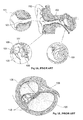
- the human ear may be described in three parts as illustrated in Figure 1A .
- the first part is the external ear 101 which includes pinna 102 for receiving and concentrating sound pressure waves to the ear canal 103.
- the second part is the middle ear 104 which receives the sound pressure waves from ear canal 103.
- the waves pass through eardrum 105 and are transformed into mechanical vibrations that are transmitted to the ossicular chain.
- the vibrations pass through malleus 106, then incus 107 and finally stapes 108.
- the third part of the human ear is known as the inner ear or cochlea 109.
- a cross-section of the cochlea 109 is shown in Figure 1B .
- the vibrations of the ossicular chain are transmitted from the stapes 108 to the perilymph liquid of the scala vestibuli 136 through the oval-shaped windows of the cochlea 109. Once in the cochlea 109, the vibrations in the liquid initiate the organ of Corti 110 to generate stimulus in the acoustic nerve 138.
- a cochlear implant 142 comprises two main parts being an external device 111 (also referred to as a speech processor) and an implantable device 113.
- Speech processor 111 is composed of a transmitting coil 112, a microphone, electronics, and a battery (not shown).
- the implantable device 113 includes a housing 114, an electronic and separate receiving coil 115, and a generally flexible lead 116 to connect the housing 114 to an electrode array 117.
- the flexible lead 116 passes through the middle ear 118 to reach the cochlea 119.
- an electrode array 121 is composed of an electrode carrier 122 made of a flexible material such as silicone in order to facilitate insertion of the array 121 into the scala tympani 120 of the cochlea 119.
- the scala tympani 120 has a helical shape 123 and the flexible material of carrier 122 allows for a folding effect.
- the electrode carrier 122 contains connection wires (not shown) that are connected to stimulation electrodes 124 made of platinum, platinum-iridium or other material having a biocompatible surface treatment.
- Figure 1E illustrates an example of an electrode array 144 composed of cylindrical electrodes 125 made of platinum-iridium. Each electrode 125 is separated from each other by a small silicone ring 126. The diameter of each silicone ring 126 regularly decreases towards proximal end 127 in order to form a progressively finer or tapered surface. Additional rings 128 are disposed on the basal diameter of the electrode array 144 to assist insertion of the array 144 into the cochlea.
- the electrode array of existing cochlear implants has an average of one electrode per each one millimeter along the array.
- a problem with existing cochlear implant systems is the realization of spatially high-resolution electrical stimulation to restore sound perception close to normal hearing.
- the stimulating current usually diffuses and stimulates a large number of spiral ganglia with low specificity if the electrode array is located far from the target cells. It is thus important to locate the electrode array close to the spiral ganglia in the cochlea (the target of the electrical stimulation).
- the electrode array of a cochlear implant is generally inserted into the scala tympani because it has the largest cross-sectional area and is an easy surgical operation site. Stimulating currents flowing from the electrode site stimulate the spiral ganglion cells located in the direction of the cochlea modiolus. Therefore, it is desirable to locate the electrode array of a cochlear implant system close to the modiolus to reduce the distance between the electrode and the spiral ganglia and increase the spatial specificity of the electrical stimulation.
- modiolus-hugging electrodes are developed, these electrode use a carrier which is held straight by an internal stylet before and during the insertion process in the scala tympani. After the partial insertion of the electrode and stylet, the electrode is pushed to its full insertion depth while holding the stylet at the same position. The electrode returns to its original spiral shape while being pushed toward the modiolus. Accordingly, the insertion depth of the stylet is critical in modiolus-hugging electrode array surgery.
- Another aspect about electrical stimulation of the auditory system includes completion of a circuit loop whereby one electrode along the intracochlear electrode array serves as the active electrode and a second serves as a return electrode.
- Monopolar stimulation mode is the most commonly used strategy where the second extracochlear return electrode is located on the case of the receiver-stimulator unit.
- Bipolar stimulation mode uses a neighboring electrode within the implanted intracochlear electrode array as the return.
- Various variations such as bipolar + 1 or bipolar + 2 are also possible.
- Other modes may include tripolar stimulation mode where current is delivered to one intracochlear electrode and its two neighboring electrodes serve as return electrodes. With different stimulation modes, one can achieve some advantages or face challenges such as in the area of power consumption and specificity of stimulation.
- the disclosure relates to transmodiolar electrode array that is suitable for transmodiolar implantation.
- the electrode array is placed into the modiolus rather than into the scala tympani, which is a conventional location for a cochlear implant electrode array.
- the modiolus is a conical shaped central axis in the cochlea. It consists of spongy bone and the cochlea turns around it.
- the spiral ganglion is situated inside the modiolus.
- the principle according to an embodiment is to stimulate directly the inner auditory nerve at the departure of the cochlea. In order to achieve this, a transmodiolar electrode is required, the transmodiolar electrode being placed into the modiolus.
- the transmodiolar electrode array is adapted to be positioned within a modiolus of a user, to receive electrical pulses from the stimulator and using the electrodes, to directly stimulate auditory nerve fibre of the user.
- the implantation may be achieved by a procedure that involves an external ear canal-type approach.
- a method of implanting an electrode array in the cochlea of a subject includes providing a transmodiolar electrode array or a transmodiolar implant including the transmodiolar array, drilling through a bony sulcus of the cochlea to access the modiolus, and inserting the electrode array into the modiolus.
- the above method may be achieved by prior to the drilling, at least partially removing the tympanic membrane in order to access the middle ear, giving access to the bony sulcus near malleus and stapes. Thereafter, creating a pathway into the modiolus by the drilling through the bony sulcus into the apex. After the placement of the lead including the transmodiolar electrode along the drilled canal pathway for accessing the modiolus, the canal is covered with bone powder and cement.
- the stimulator may be latched onto the temporal bone as in existing cochlear implantations.
- the transmodiolar electrode array is less than approximately 8 mm such as less than 7 mm such as less than 6 mm and has a width/ diameter of less than approximately 0.6 mm, such as 0.5 mm, or 0.4 mm.
- a 6 mm length of transmodiolar electrode array about 1 mm passes through the bone of the cochlea and the remaining length of about 5 mm is the active area containing the electrode array.
- the electrode arrays used in traditional cochlear implant systems are unsuitable for transmodiolar implantation due to the type, shape, and / or geometry of the electrode array in the cochlear implant system.
- the electrode arrays conventionally used for cochlear implant with an insertion into the cochlea are flexible enough to allow for folding effect, a property that is generally not desirable for transmodioloar electrode.
- one of the criteria for conventional intracochlear electrode array is to have stiffness that is low enough to facilitate folding and this requirement may become even more critical for atraumatic electrode array.
- silicone is used as a carrier in such introcochlear electrode arrays, having Young's modulus around 0.01 GPa.
- conventional electrode array in a cochlear implant lacks a sufficient number of electrodes in a small length available for transmodiolar implantation because each conventional electrode is made of a relatively large platinum core that cannot be manufactured in a smaller size with existing methods.
- An embodiment disclosed herein relates to a method of manufacturing an electrode array for a transmodiolar implant.
- the method includes providing a substrate and applying a conductive metal to a plurality of discrete portions on the substrate.
- a layer of insulation material is then applied over the conductive metal and the substrate.
- a plurality of portions of the insulation material is selectively removed in order to expose the conductive metal thereby forming a plurality of electrodes.
- the electrode array comprises a Young's modulus of at least 100 GPa.
- the applied layer of insulation material includes a single layer from which the plurality of portions are selectively removed.
- the step of applying a conductive metal to a plurality of discrete portions on the substrate includes applying a layer of conductive metal to the substrate; followed by selectively removing a plurality of portions of the conductive metal from the applied layer to expose the substrate.
- the plurality of portions of the conductive metal are selectively removed by laser ablation.
- the step of applying a conductive metal to a plurality of discrete portions on the substrate includes applying a cover having a plurality of apertures to the substrate; applying a conductive metal to the cover; and removing the cover to expose the conductive metal and the substrate.
- Utilizing a cover allows the person skilled in the art to avoid having to selectively remove a plurality of portions of the conductive metal from the applied layer for example, by laser ablation as described immediately above.
- the cover comprises a UV curing resin.
- the substrate is not electrically conductive, i.e. electrically non-conductive.
- the substrate is selected from the group consisting of alumina, zirconia, zirconia alumina composite, PEEK (polyether ether ketone), PI, and PMMA (Poly(methyl methacrylate)).
- the alumina may be a high purity alumina.
- Other long term implantable plastics may also be utilized as the substrate.
- the conductive metal is selected from the group consisting of titanium, gold, platinum, iridium and mixtures thereof.
- the conductive metal may be an alloy of two or more metals.
- the conductive metal is applied by serigraphy.
- the conductive metal is applied by deeping of a conductive paint prior to heating in a furnace.
- the conductive paint is a titanium hydrate solution.
- the conductive metal is applied by sputtering. This allows for very good control of the thickness of the conductive metal on the substrate.
- the plurality of portions of the insulation material are selectively removed by laser ablation.
- an electrode array for a transmodiolar implant includes a substrate, a conductive metal located at a plurality of discrete portions on the substrate; and a single layer of insulation material over the conductive metal and the substrate.
- the single layer of the insulation material includes a plurality of apertures that expose the conductive metal.
- the exposed conductive metal forms a plurality of electrodes.
- the electrode array of the aspects described above further includes a reference electrode located at one end of the electrode array; and a connection member in contact with the reference electrode for connecting the electrode array to a lead from a cochlear stimulator.
- the electrode array further comprises connection wires in the connection member.
- the electrode array is stiff. This facilitates insertion into the modiolus of a subject/ CI user.
- the electrode array may be substantially straight when inserted.
- the stiffness and/ or straightness is critical because the transmodiolar array needs to be adapted to be inserted in the modiolus.
- the stiffness of the transmodiolar electrode array expressed in Young's modulus, is significantly higher than the Young's Modulus of silicon, which is used for producing intracochlear electrode array.
- the Young's modulus of the transmodiolar electrode array is at least 350 times than that of the silicon such as 500 times, or 750 times or 1000 times.
- the Young's modulus for the transmodiolar electrode array is typically at least 100 GPa, such as at least 125 GPa, such as at least 150 GPa such as at least 175 GPa or at least 200GPa.
- An example of such electrode array would include zirconia substrate based transmodiolar electrode array having Young's modulus of 210 GPa.
- the stiffness of the transmodiolar electrode array varies along the length of the electrode array such that the stiffness at the distal end section is lower than that that at the other end.
- At least two electrodes of the electrode array are of substantially same size and shape. Additionally or alternatively, at least two electrodes of the electrode array are substantially different in size and shape.
- At least two electrodes of the electrode array are spaced evenly apart from each other. Additionally or alternatively, at least two electrodes of the electrode array are spaced unevenly apart from each other.
- the electrodes are spaced apart along length of the electrode array. In an embodiment, the electrodes are spaced apart along width or circumference of the electrode array.
- the electrodes are spaced apart along length of the transmodiolar electrode array such that a pair of neighboring electrodes are at different distances from a distal end of the electrode array and spaced apart around circumference of the transmodiolar electrode array.
- the distal end is defined as the tip of the electrode array.
- the transmodiolar electrode array comprising circumferentially spaced apart electrodes allows for creating enough spacing between neighboring electrodes, thereby controlling channel interaction. Also, combining the spaced apart electrodes along the length and circumference of the transmodiolar electrode array allows for accomodating more electrodes for a predefined length of the electrode array in comparison to conventional intracochlear electrode array.
- the electrodes are spaced apart along length of the transmodiolar electrode array and spaced apart around circumference of the transmodiolar electrode array such that the electrodes form a specific pattern such as at least one helical pattern around the circumference of the transmodiolar electrode array.
- a specific pattern such as at least one helical pattern around the circumference of the transmodiolar electrode array.
- the pattern may include a circular pattern.
- the electrodes include exposed metal tracks along length of the array.
- the electrode array is formed on a flat surface, convex surface, or concave surface of the substrate.
- the number of electrodes in the electrode array may vary.
- the number may include at least 16 electrodes, such as at least 18 electrodes and preferably at least 20 electrodes such as 22 electrodes or more.
- Another aspect disclosed herein relates to an electrode array for a transmodiolar implant manufactured by the method according to any one of the aspects or embodiments described above.
- the transmodiolar electrode array is used as a return/ reference electrode in combination with an intracochlear electrode array that is adapted to be positioned within the cochlea.
- electrodes of the intracochlear electrode array are adapted to produce the stimulation that produces auditory percept.
- the electrical circuit comprises i) a signal generator of the stimulator providing the electrical stimulation pulse, ii) an active electrode of the intracochlear stimulation electrode array, and iii) transmodiolar electrode array as a return electrode.
- a method of positioning a cochlear implant in a user includes implanting a receiver-stimulator within a user adjacent the ear of a user, positioning an intracochlear electrode array within a cochlea of the user, and positioning the transmodiolar electrode array within the modiolus of the user, the transmodiolar electrode array being adapted to be used as a return electrode.
- Positioning of the receiver-stimulator and intracochlear electrode array within the cochlea is performed in accordance with the known techniques.
- the transmodiolar electrody array is adapted to be used as a return electrode.
- the transmodiolar electrode array may include either transmodiolar electrode features that are described in this disclosure or a single electrode positioned within the modiolus. For same sized return electrode, the latter is preferred as it provides a larger return electrode surface area.
- Positioning of the transmodiolar return electrode may be achieved by drilling through a bony sulcus of the cochlea to access the modiolus; and inserting the transmodiolar electrode array into the modiolus.
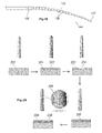
- Figure 2A illustrates a method of manufacturing an electrode array according to an embodiment of the disclosure.
- a layer of conductive metal 202 is deposited onto a substrate 201 by for example, serigraphy.
- a portion of the conductive metal is then selectively removed from the layer of conductive metal 202 such as by an ablation technique to expose the substrate 201 and create conductive areas 203 separated by an insulation zone 204.
- the conductive area 203 acts as an electrical track or electrode.
- a mask or cover having a plurality of apertures or slits or tracks is first applied to the substrate.
- a conductive metal is applied to the cover by for example, sputtering, and the cover is removed to expose the conductive areas 203 and the insulation zone 204.
- This alternative embodiment allows for avoiding use of the ablation technique to selectively remove a portion of conductive metal from the layer of conductive metal 202.
- Figure 2A illustrates two conductive areas 203 and one insulation zone 204
- the method creates many conductive areas 203 and insulation zones 204 on the substrate 201.
- Deposition of a thin insulation layer 205 then completely covers the substrate 201, conductive areas 203, and insulation zone(s) 204.
- a plurality of portions of the insulation material 205 are then selectively removed by laser ablation to form windows 206 which expose the conductive areas 203 containing the conductive metal thereby forming the electrode array.
- a substrate made of high resistance zirconia is used as a substrate 201 and electrical tracks and surface electrodes 202 were realized by metallization of gold and platinum. Thereafter, laser ablation is performed is performed and a layer of insulation material 205 such as parylen coating is applied. Surface electrodes 206 are revealed by locally removing the insulation material 205 using laser ablation.
- Electrode array 240 has a flat surface with several different sizes and shapes of surface contact electrodes 246.
- the substrate 242 and insulation layer 244 are also shown in electrode array 240.
- the flat surface may take any suitable shape such as a square, rectangle or oval.
- Electrode array 250 is formed on a substrate having a cylindrical shape with an insulation layer 254 and multiple electrodes 256 of substantially uniform size and shape that are spaced evenly apart from each other.
- the electrodes 266 are formed on a substrate with a concave surface. Insulation layer 264 is also illustrated in electrode array 260.
- Other shapes and surfaces may also be used for example, a conical shape or a convex surface.
- the different electrode patterns in Figure 2B show that the method of manufacturing an electrode array may be tailored as desired in order to obtain multiple contact areas and any number of desired styles or shapes of electrical tracks / electrodes.
- the electrodes are spaced apart along length of the transmodiolar electrode array such that a pair of neighboring electrodes are at different distances from a distal end of the electrode array and spaced apart around circumference of the transmodiolar electrode array.
- the distal end (see 252, Fig. 2D ) is defined as the tip of the electrode array.
- This is illustrated Figure 2B , in a first implementation electrodes 256 and in a second implementation electrode 266 and also in Fig. 2A as 206.
- the electrodes are spaced apart along length of the transmodiolar electrode array and spaced apart around circumference of the transmodiolar electrode array such that the electrodes form a specific pattern such as at least one helical pattern ( Fig. 2B , 256, 266) around the circumference of the transmodiolar electrode array.
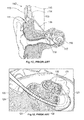
- FIG. 2C illustrates a transmodiolar implant 223 composed of an electrode array 220 connected to a cochlear stimulator 221 through a flexible lead 222.
- the electrode array 220 is coated with silicone to ensure a smooth surface.
- Electrode array 220 may be manufactured by the method according to the present disclosure as described above.
- FIG. 2D illustrates an electrode array implanted in the cochlea of a subject.
- the connection member 231 is located at the transition between the middle ear 235 and the cochlea 236.
- Connection member 231 functions to connect the active area 232 of the electrode array with lead 233 from the stimulator (not shown) using connection wires 234 located in the connection member 231.
- the connection member 231 must be able to resist handling by a surgeon using a micro forceps or other specific surgical tool as well as withstand bone growth subsequent to implantation.
- the active area 232 of the electrode array is inserted into the modiolus of the cochlea after opening by the surgeon. Active area 232 is composed of a high number of stimulating electrodes and / or recording electrodes 237.
- the active electrodes are made of a stable, biocompatible platinum-iridium material that is used in implantable medical devices.
- suitable electrodes 237 in active area 232 are electrodes forming part of the electrode arrays 240, 250, or 260 as described above and as illustrated in Figure 2B .
- the active area 232 also includes a reference electrode 238 in the shape of a ring placed at one end of the active area 232.
Landscapes
- Health & Medical Sciences (AREA)
- Animal Behavior & Ethology (AREA)
- Life Sciences & Earth Sciences (AREA)
- Veterinary Medicine (AREA)
- Engineering & Computer Science (AREA)
- Biomedical Technology (AREA)
- Nuclear Medicine, Radiotherapy & Molecular Imaging (AREA)
- Radiology & Medical Imaging (AREA)
- Public Health (AREA)
- Otolaryngology (AREA)
- General Health & Medical Sciences (AREA)
- Cardiology (AREA)
- Heart & Thoracic Surgery (AREA)
- Prostheses (AREA)
- Electrotherapy Devices (AREA)
Priority Applications (7)
| Application Number | Priority Date | Filing Date | Title |
|---|---|---|---|
| EP15176260.6A EP3017843B1 (fr) | 2014-11-07 | 2015-07-10 | Réseau d'électrodes transmodiolaires et procédé de fabrication |
| DK18152021.4T DK3348304T3 (da) | 2014-11-07 | 2015-07-10 | Transmodiolær elektrodekonfiguration og en fremstillingsmetode |
| EP18152021.4A EP3348304B1 (fr) | 2014-11-07 | 2015-07-10 | Réseau d'électrodes transmodiolaires et procédé de fabrication |
| US14/934,916 US9974945B2 (en) | 2014-11-07 | 2015-11-06 | Transmodiolar electrode array and a manufacturing method |
| AU2015252156A AU2015252156B2 (en) | 2014-11-07 | 2015-11-06 | Transmodiolar Electrode Array and a Manufacturing Method |
| CN201510758398.XA CN105581857B (zh) | 2014-11-07 | 2015-11-09 | 跨蜗轴电极阵列及制造方法 |
| US15/906,517 US10722702B2 (en) | 2014-11-07 | 2018-02-27 | Transmodiolar electrode array and a manufacturing method |
Applications Claiming Priority (2)
| Application Number | Priority Date | Filing Date | Title |
|---|---|---|---|
| EP14192294.8A EP3017842A1 (fr) | 2014-11-07 | 2014-11-07 | Réseau d'électrodes pour un implant transmodiolaire et procédé de fabrication |
| EP15176260.6A EP3017843B1 (fr) | 2014-11-07 | 2015-07-10 | Réseau d'électrodes transmodiolaires et procédé de fabrication |
Related Child Applications (2)
| Application Number | Title | Priority Date | Filing Date |
|---|---|---|---|
| EP18152021.4A Division EP3348304B1 (fr) | 2014-11-07 | 2015-07-10 | Réseau d'électrodes transmodiolaires et procédé de fabrication |
| EP18152021.4A Division-Into EP3348304B1 (fr) | 2014-11-07 | 2015-07-10 | Réseau d'électrodes transmodiolaires et procédé de fabrication |
Publications (2)
| Publication Number | Publication Date |
|---|---|
| EP3017843A1 true EP3017843A1 (fr) | 2016-05-11 |
| EP3017843B1 EP3017843B1 (fr) | 2018-05-23 |
Family
ID=51868087
Family Applications (3)
| Application Number | Title | Priority Date | Filing Date |
|---|---|---|---|
| EP14192294.8A Withdrawn EP3017842A1 (fr) | 2014-11-07 | 2014-11-07 | Réseau d'électrodes pour un implant transmodiolaire et procédé de fabrication |
| EP18152021.4A Active EP3348304B1 (fr) | 2014-11-07 | 2015-07-10 | Réseau d'électrodes transmodiolaires et procédé de fabrication |
| EP15176260.6A Active EP3017843B1 (fr) | 2014-11-07 | 2015-07-10 | Réseau d'électrodes transmodiolaires et procédé de fabrication |
Family Applications Before (2)
| Application Number | Title | Priority Date | Filing Date |
|---|---|---|---|
| EP14192294.8A Withdrawn EP3017842A1 (fr) | 2014-11-07 | 2014-11-07 | Réseau d'électrodes pour un implant transmodiolaire et procédé de fabrication |
| EP18152021.4A Active EP3348304B1 (fr) | 2014-11-07 | 2015-07-10 | Réseau d'électrodes transmodiolaires et procédé de fabrication |
Country Status (5)
| Country | Link |
|---|---|
| US (2) | US9974945B2 (fr) |
| EP (3) | EP3017842A1 (fr) |
| CN (1) | CN105581857B (fr) |
| AU (1) | AU2015252156B2 (fr) |
| DK (2) | DK3017843T3 (fr) |
Cited By (1)
| Publication number | Priority date | Publication date | Assignee | Title |
|---|---|---|---|---|
| EP3441111A1 (fr) | 2017-08-11 | 2019-02-13 | Oticon Medical A/S | Dispositif médical implantable comprenant une liaison transcutanée sans fil |
Families Citing this family (2)
| Publication number | Priority date | Publication date | Assignee | Title |
|---|---|---|---|---|
| US11738193B2 (en) * | 2016-10-28 | 2023-08-29 | Cochlear Limited | Barriers for electrodes |
| DE102020205417A1 (de) | 2020-04-29 | 2021-11-04 | Carl Von Ossietzky Universität Oldenburg | Hörprothese, insbesondere Cochlea-Implantat |
Citations (2)
| Publication number | Priority date | Publication date | Assignee | Title |
|---|---|---|---|---|
| US20120035615A1 (en) * | 2009-05-22 | 2012-02-09 | Advanced Bionics, Llc | Composite Stylet |
| US8145322B1 (en) * | 2007-07-19 | 2012-03-27 | Second Sight Medical Products, Inc. | Flexible circuit electrode array device and a method for backside processing of a flexible circuit electrode device |
Family Cites Families (14)
| Publication number | Priority date | Publication date | Assignee | Title |
|---|---|---|---|---|
| WO2004014479A2 (fr) * | 2002-08-09 | 2004-02-19 | Second Sight Medical Products, Inc | Circuit electrique isole implantable |
| US7194314B1 (en) * | 2003-08-15 | 2007-03-20 | Northwestern University | Cochlear implant including a modiolar return electrode |
| US20090143840A1 (en) * | 2006-02-06 | 2009-06-04 | Middlebrooks John C | Auditory prosthesis utilizing intra-neural stimulation of the auditory nerve |
| US7914842B1 (en) * | 2006-02-10 | 2011-03-29 | Second Sight Medical Products, Inc | Method of manufacturing a flexible circuit electrode array |
| US9011509B2 (en) * | 2007-11-30 | 2015-04-21 | Lockheed Martin Corporation | Individually optimized performance of optically stimulating cochlear implants |
| CN101366666A (zh) * | 2008-09-12 | 2009-02-18 | 上海力声特医学科技有限公司 | 一种人工耳蜗预弯电极极阵联 |
| AU2009311506A1 (en) | 2008-10-15 | 2010-05-14 | Med-El Elektromedizinische Geraete Gmbh | Implant electrode and accessories for use in robotic surgery |
| CN101413918B (zh) * | 2008-10-23 | 2012-01-04 | 上海交通大学 | 大长径比电极阵列及其制造方法 |
| ES2967456T3 (es) * | 2009-02-26 | 2024-04-30 | Abbott Diabetes Care Inc | Procedimiento de calibración de un sensor de analitos |
| US20100318167A1 (en) * | 2009-04-17 | 2010-12-16 | Otologics, Llc | Neurostimulation electrode array and method of manufacture |
| CN103889376B (zh) * | 2011-09-13 | 2017-12-08 | 听力Ip私人有限公司 | 生物相容性电极部件及其制造方法 |
| CN102512151A (zh) * | 2011-12-09 | 2012-06-27 | 中国科学院半导体研究所 | 制作立体神经微电极的方法 |
| CN103705229A (zh) * | 2012-09-29 | 2014-04-09 | 中国科学院声学研究所 | 一种用于测量耳蜗内ecap信号的方法及系统 |
| CN103932822B (zh) * | 2014-04-28 | 2017-01-11 | 中国科学院声学研究所 | 电极阵列的制作方法 |
-
2014
- 2014-11-07 EP EP14192294.8A patent/EP3017842A1/fr not_active Withdrawn
-
2015
- 2015-07-10 DK DK15176260.6T patent/DK3017843T3/en active
- 2015-07-10 DK DK18152021.4T patent/DK3348304T3/da active
- 2015-07-10 EP EP18152021.4A patent/EP3348304B1/fr active Active
- 2015-07-10 EP EP15176260.6A patent/EP3017843B1/fr active Active
- 2015-11-06 AU AU2015252156A patent/AU2015252156B2/en active Active
- 2015-11-06 US US14/934,916 patent/US9974945B2/en active Active
- 2015-11-09 CN CN201510758398.XA patent/CN105581857B/zh active Active
-
2018
- 2018-02-27 US US15/906,517 patent/US10722702B2/en active Active
Patent Citations (2)
| Publication number | Priority date | Publication date | Assignee | Title |
|---|---|---|---|---|
| US8145322B1 (en) * | 2007-07-19 | 2012-03-27 | Second Sight Medical Products, Inc. | Flexible circuit electrode array device and a method for backside processing of a flexible circuit electrode device |
| US20120035615A1 (en) * | 2009-05-22 | 2012-02-09 | Advanced Bionics, Llc | Composite Stylet |
Cited By (1)
| Publication number | Priority date | Publication date | Assignee | Title |
|---|---|---|---|---|
| EP3441111A1 (fr) | 2017-08-11 | 2019-02-13 | Oticon Medical A/S | Dispositif médical implantable comprenant une liaison transcutanée sans fil |
Also Published As
| Publication number | Publication date |
|---|---|
| EP3348304A1 (fr) | 2018-07-18 |
| EP3017842A1 (fr) | 2016-05-11 |
| CN105581857A (zh) | 2016-05-18 |
| AU2015252156B2 (en) | 2020-02-13 |
| US20180185635A1 (en) | 2018-07-05 |
| CN105581857B (zh) | 2020-03-17 |
| EP3348304B1 (fr) | 2020-07-01 |
| DK3348304T3 (da) | 2020-08-31 |
| EP3017843B1 (fr) | 2018-05-23 |
| US20160129240A1 (en) | 2016-05-12 |
| US10722702B2 (en) | 2020-07-28 |
| AU2015252156A1 (en) | 2016-05-26 |
| US9974945B2 (en) | 2018-05-22 |
| DK3017843T3 (en) | 2018-08-13 |
Similar Documents
| Publication | Publication Date | Title |
|---|---|---|
| US8452411B2 (en) | Electrode assembly for a stimulating medical device | |
| EP2588184B1 (fr) | Electrode d'implant auditif et procédé de fabrication | |
| US9056196B2 (en) | Cochlear electrode array | |
| US10016589B2 (en) | Mid-scalar electrode array | |
| US20080154339A1 (en) | Electrically Nonconductive Occludent For Tissue Openings | |
| US20090306745A1 (en) | Electrode assembly for delivering longitudinal and radial stimulation | |
| EP3057651B1 (fr) | Électrode pour malformation cochléaire de cavité commune | |
| EP2240240B1 (fr) | Conditionnement d'un canal de stimulation | |
| US20160158533A1 (en) | Tissue Penetrating Electrode | |
| EP2349464B1 (fr) | Électrode à doubles branches pour un implant cochléaire pour pénétrer dans le tissu nerveux dans le modiolus | |
| US20120245534A1 (en) | Drug Delivery Electrode with Temporary Fill Tube | |
| US10722702B2 (en) | Transmodiolar electrode array and a manufacturing method | |
| WO2008031144A1 (fr) | Réseau d'électrodes implantable | |
| WO2016012909A1 (fr) | Stimulation d'implant cochléaire | |
| CN116847903A (zh) | 具有受控孔隙度的医疗植入物电极 |
Legal Events
| Date | Code | Title | Description |
|---|---|---|---|
| PUAI | Public reference made under article 153(3) epc to a published international application that has entered the european phase |
Free format text: ORIGINAL CODE: 0009012 |
|
| AK | Designated contracting states |
Kind code of ref document: A1 Designated state(s): AL AT BE BG CH CY CZ DE DK EE ES FI FR GB GR HR HU IE IS IT LI LT LU LV MC MK MT NL NO PL PT RO RS SE SI SK SM TR |
|
| AX | Request for extension of the european patent |
Extension state: BA ME |
|
| 17P | Request for examination filed |
Effective date: 20161111 |
|
| RBV | Designated contracting states (corrected) |
Designated state(s): AL AT BE BG CH CY CZ DE DK EE ES FI FR GB GR HR HU IE IS IT LI LT LU LV MC MK MT NL NO PL PT RO RS SE SI SK SM TR |
|
| R17P | Request for examination filed (corrected) |
Effective date: 20161111 |
|
| RIC1 | Information provided on ipc code assigned before grant |
Ipc: A61N 1/05 20060101AFI20161223BHEP |
|
| GRAP | Despatch of communication of intention to grant a patent |
Free format text: ORIGINAL CODE: EPIDOSNIGR1 |
|
| INTG | Intention to grant announced |
Effective date: 20170320 |
|
| GRAJ | Information related to disapproval of communication of intention to grant by the applicant or resumption of examination proceedings by the epo deleted |
Free format text: ORIGINAL CODE: EPIDOSDIGR1 |
|
| GRAP | Despatch of communication of intention to grant a patent |
Free format text: ORIGINAL CODE: EPIDOSNIGR1 |
|
| INTC | Intention to grant announced (deleted) | ||
| GRAJ | Information related to disapproval of communication of intention to grant by the applicant or resumption of examination proceedings by the epo deleted |
Free format text: ORIGINAL CODE: EPIDOSDIGR1 |
|
| INTG | Intention to grant announced |
Effective date: 20170814 |
|
| INTG | Intention to grant announced |
Effective date: 20170823 |
|
| GRAP | Despatch of communication of intention to grant a patent |
Free format text: ORIGINAL CODE: EPIDOSNIGR1 |
|
| GRAJ | Information related to disapproval of communication of intention to grant by the applicant or resumption of examination proceedings by the epo deleted |
Free format text: ORIGINAL CODE: EPIDOSDIGR1 |
|
| INTG | Intention to grant announced |
Effective date: 20170908 |
|
| INTG | Intention to grant announced |
Effective date: 20170915 |
|
| INTG | Intention to grant announced |
Effective date: 20170922 |
|
| INTC | Intention to grant announced (deleted) | ||
| GRAP | Despatch of communication of intention to grant a patent |
Free format text: ORIGINAL CODE: EPIDOSNIGR1 |
|
| INTG | Intention to grant announced |
Effective date: 20171220 |
|
| GRAS | Grant fee paid |
Free format text: ORIGINAL CODE: EPIDOSNIGR3 |
|
| GRAA | (expected) grant |
Free format text: ORIGINAL CODE: 0009210 |
|
| AK | Designated contracting states |
Kind code of ref document: B1 Designated state(s): AL AT BE BG CH CY CZ DE DK EE ES FI FR GB GR HR HU IE IS IT LI LT LU LV MC MK MT NL NO PL PT RO RS SE SI SK SM TR |
|
| REG | Reference to a national code |
Ref country code: GB Ref legal event code: FG4D |
|
| REG | Reference to a national code |
Ref country code: CH Ref legal event code: EP |
|
| REG | Reference to a national code |
Ref country code: IE Ref legal event code: FG4D |
|
| REG | Reference to a national code |
Ref country code: DE Ref legal event code: R096 Ref document number: 602015011357 Country of ref document: DE |
|
| REG | Reference to a national code |
Ref country code: AT Ref legal event code: REF Ref document number: 1001034 Country of ref document: AT Kind code of ref document: T Effective date: 20180615 |
|
| REG | Reference to a national code |
Ref country code: FR Ref legal event code: PLFP Year of fee payment: 4 |
|
| REG | Reference to a national code |
Ref country code: DK Ref legal event code: T3 Effective date: 20180806 |
|
| REG | Reference to a national code |
Ref country code: SE Ref legal event code: TRGR |
|
| REG | Reference to a national code |
Ref country code: NL Ref legal event code: MP Effective date: 20180523 |
|
| REG | Reference to a national code |
Ref country code: LT Ref legal event code: MG4D |
|
| PG25 | Lapsed in a contracting state [announced via postgrant information from national office to epo] |
Ref country code: ES Free format text: LAPSE BECAUSE OF FAILURE TO SUBMIT A TRANSLATION OF THE DESCRIPTION OR TO PAY THE FEE WITHIN THE PRESCRIBED TIME-LIMIT Effective date: 20180523 Ref country code: LT Free format text: LAPSE BECAUSE OF FAILURE TO SUBMIT A TRANSLATION OF THE DESCRIPTION OR TO PAY THE FEE WITHIN THE PRESCRIBED TIME-LIMIT Effective date: 20180523 Ref country code: NO Free format text: LAPSE BECAUSE OF FAILURE TO SUBMIT A TRANSLATION OF THE DESCRIPTION OR TO PAY THE FEE WITHIN THE PRESCRIBED TIME-LIMIT Effective date: 20180823 Ref country code: BG Free format text: LAPSE BECAUSE OF FAILURE TO SUBMIT A TRANSLATION OF THE DESCRIPTION OR TO PAY THE FEE WITHIN THE PRESCRIBED TIME-LIMIT Effective date: 20180823 Ref country code: FI Free format text: LAPSE BECAUSE OF FAILURE TO SUBMIT A TRANSLATION OF THE DESCRIPTION OR TO PAY THE FEE WITHIN THE PRESCRIBED TIME-LIMIT Effective date: 20180523 |
|
| PG25 | Lapsed in a contracting state [announced via postgrant information from national office to epo] |
Ref country code: NL Free format text: LAPSE BECAUSE OF FAILURE TO SUBMIT A TRANSLATION OF THE DESCRIPTION OR TO PAY THE FEE WITHIN THE PRESCRIBED TIME-LIMIT Effective date: 20180523 Ref country code: LV Free format text: LAPSE BECAUSE OF FAILURE TO SUBMIT A TRANSLATION OF THE DESCRIPTION OR TO PAY THE FEE WITHIN THE PRESCRIBED TIME-LIMIT Effective date: 20180523 Ref country code: RS Free format text: LAPSE BECAUSE OF FAILURE TO SUBMIT A TRANSLATION OF THE DESCRIPTION OR TO PAY THE FEE WITHIN THE PRESCRIBED TIME-LIMIT Effective date: 20180523 Ref country code: HR Free format text: LAPSE BECAUSE OF FAILURE TO SUBMIT A TRANSLATION OF THE DESCRIPTION OR TO PAY THE FEE WITHIN THE PRESCRIBED TIME-LIMIT Effective date: 20180523 Ref country code: GR Free format text: LAPSE BECAUSE OF FAILURE TO SUBMIT A TRANSLATION OF THE DESCRIPTION OR TO PAY THE FEE WITHIN THE PRESCRIBED TIME-LIMIT Effective date: 20180824 |
|
| PG25 | Lapsed in a contracting state [announced via postgrant information from national office to epo] |
Ref country code: SK Free format text: LAPSE BECAUSE OF FAILURE TO SUBMIT A TRANSLATION OF THE DESCRIPTION OR TO PAY THE FEE WITHIN THE PRESCRIBED TIME-LIMIT Effective date: 20180523 Ref country code: EE Free format text: LAPSE BECAUSE OF FAILURE TO SUBMIT A TRANSLATION OF THE DESCRIPTION OR TO PAY THE FEE WITHIN THE PRESCRIBED TIME-LIMIT Effective date: 20180523 Ref country code: PL Free format text: LAPSE BECAUSE OF FAILURE TO SUBMIT A TRANSLATION OF THE DESCRIPTION OR TO PAY THE FEE WITHIN THE PRESCRIBED TIME-LIMIT Effective date: 20180523 Ref country code: RO Free format text: LAPSE BECAUSE OF FAILURE TO SUBMIT A TRANSLATION OF THE DESCRIPTION OR TO PAY THE FEE WITHIN THE PRESCRIBED TIME-LIMIT Effective date: 20180523 Ref country code: CZ Free format text: LAPSE BECAUSE OF FAILURE TO SUBMIT A TRANSLATION OF THE DESCRIPTION OR TO PAY THE FEE WITHIN THE PRESCRIBED TIME-LIMIT Effective date: 20180523 |
|
| REG | Reference to a national code |
Ref country code: DE Ref legal event code: R097 Ref document number: 602015011357 Country of ref document: DE |
|
| PG25 | Lapsed in a contracting state [announced via postgrant information from national office to epo] |
Ref country code: SM Free format text: LAPSE BECAUSE OF FAILURE TO SUBMIT A TRANSLATION OF THE DESCRIPTION OR TO PAY THE FEE WITHIN THE PRESCRIBED TIME-LIMIT Effective date: 20180523 Ref country code: IT Free format text: LAPSE BECAUSE OF FAILURE TO SUBMIT A TRANSLATION OF THE DESCRIPTION OR TO PAY THE FEE WITHIN THE PRESCRIBED TIME-LIMIT Effective date: 20180523 |
|
| PG25 | Lapsed in a contracting state [announced via postgrant information from national office to epo] |
Ref country code: LU Free format text: LAPSE BECAUSE OF NON-PAYMENT OF DUE FEES Effective date: 20180710 Ref country code: MC Free format text: LAPSE BECAUSE OF FAILURE TO SUBMIT A TRANSLATION OF THE DESCRIPTION OR TO PAY THE FEE WITHIN THE PRESCRIBED TIME-LIMIT Effective date: 20180523 |
|
| PLBE | No opposition filed within time limit |
Free format text: ORIGINAL CODE: 0009261 |
|
| STAA | Information on the status of an ep patent application or granted ep patent |
Free format text: STATUS: NO OPPOSITION FILED WITHIN TIME LIMIT |
|
| REG | Reference to a national code |
Ref country code: BE Ref legal event code: MM Effective date: 20180731 |
|
| REG | Reference to a national code |
Ref country code: IE Ref legal event code: MM4A |
|
| PG25 | Lapsed in a contracting state [announced via postgrant information from national office to epo] |
Ref country code: IE Free format text: LAPSE BECAUSE OF NON-PAYMENT OF DUE FEES Effective date: 20180710 |
|
| 26N | No opposition filed |
Effective date: 20190226 |
|
| PG25 | Lapsed in a contracting state [announced via postgrant information from national office to epo] |
Ref country code: SI Free format text: LAPSE BECAUSE OF FAILURE TO SUBMIT A TRANSLATION OF THE DESCRIPTION OR TO PAY THE FEE WITHIN THE PRESCRIBED TIME-LIMIT Effective date: 20180523 Ref country code: BE Free format text: LAPSE BECAUSE OF NON-PAYMENT OF DUE FEES Effective date: 20180731 |
|
| PG25 | Lapsed in a contracting state [announced via postgrant information from national office to epo] |
Ref country code: AL Free format text: LAPSE BECAUSE OF FAILURE TO SUBMIT A TRANSLATION OF THE DESCRIPTION OR TO PAY THE FEE WITHIN THE PRESCRIBED TIME-LIMIT Effective date: 20180523 |
|
| PG25 | Lapsed in a contracting state [announced via postgrant information from national office to epo] |
Ref country code: MT Free format text: LAPSE BECAUSE OF NON-PAYMENT OF DUE FEES Effective date: 20180710 |
|
| PG25 | Lapsed in a contracting state [announced via postgrant information from national office to epo] |
Ref country code: TR Free format text: LAPSE BECAUSE OF FAILURE TO SUBMIT A TRANSLATION OF THE DESCRIPTION OR TO PAY THE FEE WITHIN THE PRESCRIBED TIME-LIMIT Effective date: 20180523 |
|
| PG25 | Lapsed in a contracting state [announced via postgrant information from national office to epo] |
Ref country code: PT Free format text: LAPSE BECAUSE OF FAILURE TO SUBMIT A TRANSLATION OF THE DESCRIPTION OR TO PAY THE FEE WITHIN THE PRESCRIBED TIME-LIMIT Effective date: 20180523 |
|
| PG25 | Lapsed in a contracting state [announced via postgrant information from national office to epo] |
Ref country code: CY Free format text: LAPSE BECAUSE OF FAILURE TO SUBMIT A TRANSLATION OF THE DESCRIPTION OR TO PAY THE FEE WITHIN THE PRESCRIBED TIME-LIMIT Effective date: 20180523 Ref country code: HU Free format text: LAPSE BECAUSE OF FAILURE TO SUBMIT A TRANSLATION OF THE DESCRIPTION OR TO PAY THE FEE WITHIN THE PRESCRIBED TIME-LIMIT; INVALID AB INITIO Effective date: 20150710 Ref country code: MK Free format text: LAPSE BECAUSE OF NON-PAYMENT OF DUE FEES Effective date: 20180523 |
|
| PG25 | Lapsed in a contracting state [announced via postgrant information from national office to epo] |
Ref country code: IS Free format text: LAPSE BECAUSE OF FAILURE TO SUBMIT A TRANSLATION OF THE DESCRIPTION OR TO PAY THE FEE WITHIN THE PRESCRIBED TIME-LIMIT Effective date: 20180923 |
|
| REG | Reference to a national code |
Ref country code: AT Ref legal event code: UEP Ref document number: 1001034 Country of ref document: AT Kind code of ref document: T Effective date: 20180523 |
|
| PGFP | Annual fee paid to national office [announced via postgrant information from national office to epo] |
Ref country code: GB Payment date: 20230703 Year of fee payment: 9 Ref country code: CH Payment date: 20230801 Year of fee payment: 9 Ref country code: AT Payment date: 20230704 Year of fee payment: 9 |
|
| PGFP | Annual fee paid to national office [announced via postgrant information from national office to epo] |
Ref country code: SE Payment date: 20230703 Year of fee payment: 9 Ref country code: FR Payment date: 20230703 Year of fee payment: 9 Ref country code: DK Payment date: 20230703 Year of fee payment: 9 Ref country code: DE Payment date: 20230704 Year of fee payment: 9 |