EP3017492B1 - Method for shutting down a system comprising a fuel cell stack and system comprising a fuel cell stack - Google Patents
Method for shutting down a system comprising a fuel cell stack and system comprising a fuel cell stack Download PDFInfo
- Publication number
- EP3017492B1 EP3017492B1 EP14735544.0A EP14735544A EP3017492B1 EP 3017492 B1 EP3017492 B1 EP 3017492B1 EP 14735544 A EP14735544 A EP 14735544A EP 3017492 B1 EP3017492 B1 EP 3017492B1
- Authority
- EP
- European Patent Office
- Prior art keywords
- fuel
- cell stack
- hydrogen
- gas
- fuel cell
- Prior art date
- Legal status (The legal status is an assumption and is not a legal conclusion. Google has not performed a legal analysis and makes no representation as to the accuracy of the status listed.)
- Active
Links
Images

Classifications
-
- H—ELECTRICITY
- H01—ELECTRIC ELEMENTS
- H01M—PROCESSES OR MEANS, e.g. BATTERIES, FOR THE DIRECT CONVERSION OF CHEMICAL ENERGY INTO ELECTRICAL ENERGY
- H01M8/00—Fuel cells; Manufacture thereof
- H01M8/04—Auxiliary arrangements, e.g. for control of pressure or for circulation of fluids
- H01M8/04223—Auxiliary arrangements, e.g. for control of pressure or for circulation of fluids during start-up or shut-down; Depolarisation or activation, e.g. purging; Means for short-circuiting defective fuel cells
- H01M8/04231—Purging of the reactants
-
- H—ELECTRICITY
- H01—ELECTRIC ELEMENTS
- H01M—PROCESSES OR MEANS, e.g. BATTERIES, FOR THE DIRECT CONVERSION OF CHEMICAL ENERGY INTO ELECTRICAL ENERGY
- H01M8/00—Fuel cells; Manufacture thereof
- H01M8/04—Auxiliary arrangements, e.g. for control of pressure or for circulation of fluids
- H01M8/04298—Processes for controlling fuel cells or fuel cell systems
- H01M8/043—Processes for controlling fuel cells or fuel cell systems applied during specific periods
- H01M8/04303—Processes for controlling fuel cells or fuel cell systems applied during specific periods applied during shut-down
-
- H—ELECTRICITY
- H01—ELECTRIC ELEMENTS
- H01M—PROCESSES OR MEANS, e.g. BATTERIES, FOR THE DIRECT CONVERSION OF CHEMICAL ENERGY INTO ELECTRICAL ENERGY
- H01M8/00—Fuel cells; Manufacture thereof
- H01M8/04—Auxiliary arrangements, e.g. for control of pressure or for circulation of fluids
- H01M8/04298—Processes for controlling fuel cells or fuel cell systems
- H01M8/04694—Processes for controlling fuel cells or fuel cell systems characterised by variables to be controlled
- H01M8/04746—Pressure; Flow
- H01M8/04753—Pressure; Flow of fuel cell reactants
-
- H—ELECTRICITY
- H01—ELECTRIC ELEMENTS
- H01M—PROCESSES OR MEANS, e.g. BATTERIES, FOR THE DIRECT CONVERSION OF CHEMICAL ENERGY INTO ELECTRICAL ENERGY
- H01M8/00—Fuel cells; Manufacture thereof
- H01M8/10—Fuel cells with solid electrolytes
- H01M2008/1095—Fuel cells with polymeric electrolytes
-
- H—ELECTRICITY
- H01—ELECTRIC ELEMENTS
- H01M—PROCESSES OR MEANS, e.g. BATTERIES, FOR THE DIRECT CONVERSION OF CHEMICAL ENERGY INTO ELECTRICAL ENERGY
- H01M8/00—Fuel cells; Manufacture thereof
- H01M8/04—Auxiliary arrangements, e.g. for control of pressure or for circulation of fluids
- H01M8/04298—Processes for controlling fuel cells or fuel cell systems
- H01M8/04694—Processes for controlling fuel cells or fuel cell systems characterised by variables to be controlled
- H01M8/04858—Electric variables
- H01M8/04925—Power, energy, capacity or load
- H01M8/04947—Power, energy, capacity or load of auxiliary devices, e.g. batteries, capacitors
-
- Y—GENERAL TAGGING OF NEW TECHNOLOGICAL DEVELOPMENTS; GENERAL TAGGING OF CROSS-SECTIONAL TECHNOLOGIES SPANNING OVER SEVERAL SECTIONS OF THE IPC; TECHNICAL SUBJECTS COVERED BY FORMER USPC CROSS-REFERENCE ART COLLECTIONS [XRACs] AND DIGESTS
- Y02—TECHNOLOGIES OR APPLICATIONS FOR MITIGATION OR ADAPTATION AGAINST CLIMATE CHANGE
- Y02E—REDUCTION OF GREENHOUSE GAS [GHG] EMISSIONS, RELATED TO ENERGY GENERATION, TRANSMISSION OR DISTRIBUTION
- Y02E60/00—Enabling technologies; Technologies with a potential or indirect contribution to GHG emissions mitigation
- Y02E60/30—Hydrogen technology
- Y02E60/50—Fuel cells
Definitions
- the present invention relates to fuel cells, in particular but not exclusively to electrolyte-type fuel cells in the form of a polymer membrane (ie of the PEFC type for Polymer Electrolyte Fuel Cell or PEMFC for Proton Exchange Fuel Cell Membrane).
- a polymer membrane ie of the PEFC type for Polymer Electrolyte Fuel Cell or PEMFC for Proton Exchange Fuel Cell Membrane.
- a fuel cell generally comprises the series combination of unitary elements, which each consist essentially of an anode and a cathode separated by a polymer membrane allowing the passage of ions from the anode to the cathode .
- the anode supplied with fuel for example hydrogen
- the cathode fed with oxidant for example pure oxygen or contained in air
- oxidant for example pure oxygen or contained in air
- the purpose of the present invention is to propose a method for maintaining the performance of a fuel cell without disrupting its operation and without creating additional degradation.
- the hydrogen present at the anode makes it possible to guarantee a maintenance of the electrochemical potential at 0V. Consequently, when the hydrogen disappears, an increase in this electrochemical potential follows. However, if the electrochemical potential exceeds a certain predetermined threshold, the chemical species absorbed by a catalyst of the fuel cell during secondary reactions occurring during operation of the battery are released. This desorption leads to cleaning, allowing the catalyst to find a larger active surface. As a result, the catalyst performance increases, thereby increasing the performance of the fuel cell.
- the battery is off when the residual voltage between the anode and the cathode becomes very low, for example less than or equal to 0.06 volts.
- the final step to remove hydrogen can be done either at each stop of the battery, or less often.
- the step of eliminating the hydrogen comprises a mechanical suction step.
- This aspiration is, for example, performed by a vacuum pump.
- operation of the vacuum pump for a period of two minutes can extract 90% of the hydrogen still present at the anode after extinction.
- the step of removing the hydrogen comprises a blowing step, consisting in injecting the cathode with nitrogen at overpressure, intended to replace the hydrogen.
- the step of removing the hydrogen is carried out by consuming the hydrogen by means of a resistance installed at the terminals of the fuel cell.
- the step of eliminating the hydrogen comprises an electrochemical pumping step, using an electrochemical membrane installed outside the stack.
- an electrochemical membrane operates on the same principle as the cells forming the stack of the fuel cell, and thus makes it possible to consume hydrogen by electrochemical reactions similar to those which take place during the operation of the cell.
- this means of removing hydrogen employing an electrochemical membrane may be used alone or in combination with the other hydrogen deflection means mentioned above.
- the resistance installed at the terminals of the fuel cell is used to consume residual hydrogen residues after application of another of the aforementioned means.
- a three-way valve is used to alternate a stage where the cell is evacuated and a stage where the gases still present in the stack are mixed to ensure that each vacuum step actually makes it possible to eliminate hydrogen in all the cells.
- the invention also relates to a method for starting an electrolyte membrane fuel cell comprising an initial step of aspirating oxidant gas present at the anode before injecting the fuel gas.
- oxidant gas has replaced the hydrogen in the entire stack, including at the level of the anode. Therefore, before injecting the hydrogen to start a cycle of operation, it is necessary to remove the oxidizing gas to prevent it cohabit with hydrogen on the same electrode, which would result in the creation of plane voltages, harmful to the durability of the battery.
- this starting method can be implemented independently of the present invention.
- the means capable of causing a disappearance of hydrogen comprise a vacuum pump installed in the fuel gas supply circuit.
- the means capable of causing a disappearance of the hydrogen comprise a resistance installed in parallel with the fuel cell.
- a fuel cell 1b of the electrolyte type is shown in the form of a polymer membrane (ie of the PEFC type for Polymer Electrolyte Fuel Cell or PEMFC for Proton Exchange Membrane Fuel Cell).
- the fuel cell 1b is supplied by two gases, namely the fuel (the hydrogen stored or manufactured on board the vehicle) and the oxidizer (air or pure oxygen) which feed the electrodes of the electrochemical cells.
- An electric charge 14 is connected to the fuel cell 1b by an electrical line 10.
- figure 1 represents elements of the cathode circuit useful for understanding the invention, although the object of the present application relates essentially to the anode circuit of a fuel cell.
- the installation comprises a fuel supply circuit 11 fuel gas anode side.
- a tank 11T of pure hydrogen H 2 is connected to the inlet of the anode circuit of the fuel cell 1b by means of a supply pipe which passes through a shut-off valve 110 and then by a control valve.
- pressure 117 then by an ejector 113, then by a supply channel 11A fuel gas leading to the anodes.
- a pressure sensor (not shown) is installed on the supply channel 11A just prior to entry into the fuel cell 1b.
- the hydrogen supply circuit 11 (the fuel) also comprises a recycling circuit 11R of hydrogen not consumed by the fuel cell, connected to the output of the anode circuit of the fuel cell 1b.
- a water separator 114 is installed on the recycling circuit 11R.
- the ejector 113 and a recirculation pump 115 ensure the recycling of the unconsumed hydrogen and the mixture with fresh hydrogen from the tank.
- an additional accumulation chamber of fuel gas 116 disposed on the piping of the fuel gas supply circuit 11, between the shutoff valve 110 and a pressure regulating valve 117.
- the additional accumulation chamber is, in this preferred embodiment, placed where the pressure is highest in the supply circuit, so as to reduce the volume, or the same volume, so as to store a larger amount of hydrogen.
- the additional accumulation chamber of fuel gas 116 could be disposed at any point of the fuel gas supply circuit, that is to say at any point between the shutoff valve 110 and the fuel cell 1b, even on the recycling circuit 11R, or on the circuit between the water separator 114 and the ejector 113. However it is interesting to place it at a point in the circuit where the pressure is higher so to reduce the volume.
- the position upstream of the pressure regulating valve makes possible a controlled discharge of said accumulation chamber.
- a suction pump 119 and a shut-off valve 118 installed on a pipe terminating in the atmosphere and connected to the recirculation loop 11R of the fuel gas, preferably under the water separator 114.
- the connection to this precise location, shown at figure 1 by controlling the shutoff valve 118 to provide the triple function of water evacuation, purging, and aspiration of hydrogen.
- this detail of embodiment is not limiting.
- the line comprising the shutoff valve 118 could be connected to any location downstream of the pressure regulating valve 117.
- the suction pump 119 and the shutoff valve 118 are capable of being controlled so as to suck the hydrogen after the battery has been extinguished, in order to cause it to disappear completely.
- the load 14 corresponds to the resistance previously mentioned.
- the other means provided by the present invention, such as the electrochemical membrane are not shown in this figure.
- the installation also comprises a supply circuit 12b in combustion gas on the cathodes side.
- This circuit comprises an air compressor 125b serving in normal use to supply the atmospheric air fuel cell 126 by means of a supply pipe which passes through a shut-off valve 128, then via a supply channel 12A. oxidizing gas leading to the cathodes.
- an oxygen tank would be located instead of the air inlet 126.
- the air supply circuit 12, containing oxygen also comprises a recycling circuit 12R oxygen not consumed by the fuel cell, connected to the output of the cathode circuit of the fuel cell 1b.
- the recycling circuit 12Rb is directly connected to the supply channel 12A by a branch branch 123b downstream of the air compressor 125b.
- a pressure regulating valve 122 makes it possible to continuously exhaust the depleted air towards the atmosphere. The degree of opening of this pressure regulating valve 122 is controlled to maintain the pressure at the desired value in the cathode circuit.
- the recycling circuit In normal operation of the fuel cell, the recycling circuit is not used, the pump 125 is stopped, and no gas flows in the recycling circuit 12Rb which becomes virtually nonexistent. The entire gas not consumed by the cathode circuit is directed to the atmosphere through the pressure regulating valve 122b. In the case where the pump 125 does not naturally provide the anti-return function when it is stopped, a non-return valve must be provided on the recycling circuit 12Rb so as to guarantee the passage of the whole of the pump. air supplied by the compressor to the cathode circuit of the fuel cell 1b.
- the shut-off valve 128 makes it possible to isolate the cathode circuit from atmospheric air when the battery is at a standstill.
- This shutoff valve 128 can indifferently be placed upstream or downstream of the compressor.
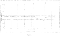
- the figure 2 shows the performance of a 16-cell fuel cell embodying the invention. Each point of the curve is recorded as soon as the temperature and current have reached their nominal value (70 ° C - 100A), and represents the average voltage cells after each start of the stack. In the exemplary implementation, the stack is subjected to repeated stopping and starting cycles of about 1 hour.
- the x-axis shows the cumulative operating hours of the fuel cell
- the y-axis shows the average cell voltage. From the time to, corresponding to the beginning of the curve, to the time t1 represented by a first vertical line, the step of removing the hydrogen is performed after each extinction of the stack. It can be seen that the performance of the cell does not decrease, since the average voltage of the cells remains almost constant during the repeated cycling of the fuel cell.
- the present invention effectively maintains the performance of the fuel cell without degrading it.
Description
La présente invention se rapporte aux piles à combustibles, en particulier mais non exclusivement aux piles à combustible du type à électrolyte sous la forme d'une membrane polymère (c'est à dire de type PEFC pour Polymer Electrolyte Fuel Cell ou PEMFC pour Proton Exchange Membrane Fuel Cell).The present invention relates to fuel cells, in particular but not exclusively to electrolyte-type fuel cells in the form of a polymer membrane (ie of the PEFC type for Polymer Electrolyte Fuel Cell or PEMFC for Proton Exchange Fuel Cell Membrane).
On sait que les piles à combustibles permettent la production directe d'énergie électrique par une réaction électrochimique d'oxydoréduction à partir d'un gaz carburant et d'un gaz comburant, sans passer par une conversion en énergie mécanique. Cette technologie semble prometteuse notamment pour des applications automobiles. Une pile à combustible comporte en général l'association en série d'éléments unitaires qui, chacun, sont constitués essentiellement d'une anode et d'une cathode séparées par une membrane polymère permettant le passage d'ions de l'anode à la cathode.It is known that fuel cells allow the direct production of electrical energy by an electrochemical oxidation-reduction reaction from a fuel gas and an oxidizing gas, without passing through a conversion to mechanical energy. This technology seems promising especially for automotive applications. A fuel cell generally comprises the series combination of unitary elements, which each consist essentially of an anode and a cathode separated by a polymer membrane allowing the passage of ions from the anode to the cathode .
Ainsi, l'anode alimentée en carburant, par exemple de l'hydrogène, est le siège d'une demi-réaction d'oxydation. Dans le même temps, la cathode alimentée en comburant, par exemple de l'oxygène pur ou contenu dans de l'air, est le siège d'une demi-réaction de réduction. Afin que ces deux demi-réactions soient possibles, il est nécessaire de charger l'anode et la cathode en catalyseur, à savoir un composé capable d'augmenter la vitesse de réaction, sans toutefois être lui-même consommé. Parmi les différents catalyseurs employés, on a constaté que les meilleures performances étaient obtenues en utilisant du platine, seul ou en alliage.Thus, the anode supplied with fuel, for example hydrogen, is the seat of an oxidation half-reaction. At the same time, the cathode fed with oxidant, for example pure oxygen or contained in air, is the seat of a half-reduction reaction. In order for these two half reactions to be possible, it is necessary to charge the anode and the cathode as a catalyst, namely a compound capable of increasing the reaction rate, without itself being consumed. Among the various catalysts employed, it has been found that the best performances were obtained using platinum, alone or in alloy.
Afin d'éviter toute dégradation de la pile à combustible et notamment des catalyseurs lors des nombreux arrêts / redémarrage subis au cours de la vie d'une pile, il est nécessaire de prévoir des procédures d'arrêt spécifiques, telle que celle décrite dans la demande de brevet
Toutefois, on a constaté une baisse des performances de la pile à combustible après quelques cycles arrêts / redémarrage. Par conséquent, l'objectif de la présente invention est de proposer un procédé permettant de maintenir les performances d'une pile à combustible sans en perturber le fonctionnement et sans créer de dégradation annexes.However, there has been a decline in performance of the fuel cell after a few cycles stops / restart. Therefore, the purpose of the present invention is to propose a method for maintaining the performance of a fuel cell without disrupting its operation and without creating additional degradation.
L'invention propose ainsi un procédé d'arrêt d'une pile à combustible à membrane électrolyte polymère selon la revendication 1, la pile à combustible étant installée dans un système comprenant un circuit d'alimentation en gaz carburant reliant un réservoir de gaz carburant à l'anode de la pile à combustible, et un circuit d'alimentation en gaz comburant reliant un réservoir de gaz comburant, ou l'air atmosphérique, le gaz carburant étant de l'hydrogène, et le procédé comprenant les étapes suivantes :
- (i) coupure de l'alimentation en gaz carburant et en gaz comburant,
- (ii) maintien d'un prélèvement de courant tant que le gaz comburant n'est pas consommé ;
- (iii) injection de gaz enrichi en azote dans le système d'alimentation en gaz comburant et le procédé étant caractérisé en ce que, à l'issue de la procédure d'arrêt, on fait disparaître totalement l'hydrogène encore présent à l'anode de la pile à combustible, effectuée après extinction complète de la pile à combustible, cette étape comprenant une étape de pompage électrochimique mettant en oeuvre une membrane électrochimique installée en dehors de l'empilement.
- (i) shutting off the supply of fuel gas and oxidizing gas,
- (ii) maintaining a current draw until the oxidizing gas is consumed;
- (iii) injecting nitrogen-enriched gas into the combustion gas supply system and the method being characterized in that, after the shutdown procedure, the hydrogen still present in the gas is completely removed; anode of the fuel cell, performed after complete extinction of the fuel cell, this step comprising an electrochemical pumping step using an electrochemical membrane installed outside the stack.
L'hydrogène présent à l'anode permet de garantir un maintien du potentiel électrochimique à 0V. Par conséquent, lorsque l'hydrogène disparaît, s'en suit une augmentation de ce potentiel électrochimique. Or, si le potentiel électrochimique dépasse un certain seuil prédéterminé, les espèces chimiques absorbées par un catalyseur de la pile à combustible lors de réactions secondaires se produisant au cours du fonctionnement de la pile sont relâchées. Cette désorption conduit à un nettoyage, permettant au catalyseur de retrouver une surface active plus importante. Par conséquent, les performances du catalyseur augmentent, permettant ainsi d'augmenter les performances de la pile à combustible.The hydrogen present at the anode makes it possible to guarantee a maintenance of the electrochemical potential at 0V. Consequently, when the hydrogen disappears, an increase in this electrochemical potential follows. However, if the electrochemical potential exceeds a certain predetermined threshold, the chemical species absorbed by a catalyst of the fuel cell during secondary reactions occurring during operation of the battery are released. This desorption leads to cleaning, allowing the catalyst to find a larger active surface. As a result, the catalyst performance increases, thereby increasing the performance of the fuel cell.
On précise ici que cette disparition d'hydrogène ne doit s'effectuer qu'après extinction complète de la pile à combustible. En effet, une absence partielle ou totale d'hydrogène pendant la procédure d'arrêt conduirait aux réactions suivantes :
- Corrosion à l'anode du carbone qui supporte le catalyseur,
- Dissolution du platine à la cathode,
- Diminution irréversible de l'activité catalytique, et
- Inversion du potentiel entre l'anode et la cathode dans le cas d'une pile à combustible composée de plusieurs cellules.
- Corrosion at the anode of the carbon which supports the catalyst,
- Dissolution of platinum at the cathode,
- Irreversible decrease in catalytic activity, and
- Inverting the potential between the anode and the cathode in the case of a fuel cell composed of several cells.
De telles réactions seraient contre-productives, puisqu'elles diminueraient les performances de la pile à combustible, et annuleraient ainsi tout le bénéfice du procédé selon la présente invention. On considère que la pile est éteinte dès lors que la tension résiduelle entre l'anode et la cathode devient très faible, par exemple inférieure ou égale à 0.06 volts. L'ultime étape de faire disparaître l'hydrogène peut être effectuée soit à chaque arrêt de la pile, soit moins souvent.Such reactions would be counterproductive, since they would decrease the performance of the fuel cell, and thus negate the full benefit of the process according to the present invention. It is considered that the battery is off when the residual voltage between the anode and the cathode becomes very low, for example less than or equal to 0.06 volts. The final step to remove hydrogen can be done either at each stop of the battery, or less often.
Dans une réalisation avantageuse de l'invention, l'étape de faire disparaître l'hydrogène comprend une étape d'aspiration mécanique. Cette aspiration est, par exemple, effectuée par une pompe à vide. Par exemple, dans une configuration telle que décrite ultérieurement à l'aide des figures, un fonctionnement de la pompe à vide pendant une durée de deux minutes permet d'extraire 90% de l'hydrogène encore présent à l'anode après extinction.In an advantageous embodiment of the invention, the step of eliminating the hydrogen comprises a mechanical suction step. This aspiration is, for example, performed by a vacuum pump. For example, in a configuration as described later using the figures, operation of the vacuum pump for a period of two minutes can extract 90% of the hydrogen still present at the anode after extinction.
Dans une réalisation avantageuse de l'invention, l'étape de faire disparaître l'hydrogène comprend une étape de soufflage, consistant à injecter à la cathode de l'azote en surpression, destiné à remplacer l'hydrogène.In an advantageous embodiment of the invention, the step of removing the hydrogen comprises a blowing step, consisting in injecting the cathode with nitrogen at overpressure, intended to replace the hydrogen.
Dans une réalisation avantageuse de l'invention, l'étape de faire disparaître l'hydrogène est effectuée en consommant l'hydrogène au moyen d'une résistance installée aux bornes de la pile à combustible.In an advantageous embodiment of the invention, the step of removing the hydrogen is carried out by consuming the hydrogen by means of a resistance installed at the terminals of the fuel cell.
Selon l'invention, l'étape de faire disparaître l'hydrogène comprend une étape de pompage électrochimique, mettant en oeuvre une membrane électrochimique installée en dehors de l'empilement. Une telle membrane électrochimique fonctionne sur le même principe que les cellules formant l'empilement de la pile à combustible, et permet ainsi de consommer l'hydrogène par des réactions électrochimiques similaires à celles qui se déroulent lors du fonctionnement de la pile.According to the invention, the step of eliminating the hydrogen comprises an electrochemical pumping step, using an electrochemical membrane installed outside the stack. Such an electrochemical membrane operates on the same principle as the cells forming the stack of the fuel cell, and thus makes it possible to consume hydrogen by electrochemical reactions similar to those which take place during the operation of the cell.
Il est à noter que ce moyen de faire disparaître l'hydrogène employant une membrane électrochimique peut être utilisé seul ou en combinaison avec les autres moyens de disparation de l'hydrogène mentionnés auparavant. Ainsi, dans une réalisation avantageuse, la résistance installée aux bornes de la pile à combustible est utilisée pour consommer les résidus d'hydrogène restant après application d'un autre des moyens précités.It should be noted that this means of removing hydrogen employing an electrochemical membrane may be used alone or in combination with the other hydrogen deflection means mentioned above. Thus, in an advantageous embodiment, the resistance installed at the terminals of the fuel cell is used to consume residual hydrogen residues after application of another of the aforementioned means.
On a constaté que l'utilisation de la pompe à vide, par exemple, conduisait à une pénurie d'hydrogène locale dans certaines cellules, tout en laissant de l'hydrogène présent dans d'autres. Pour remédier à cela, dans une réalisation avantageuse, on utilise une vanne trois voies pour alterner une étape où l'on fait le vide dans la pile et une étape où l'on mélange les gaz encore présents dans la pile, pour s'assurer que chaque étape de vide permet effectivement de faire disparaître l'hydrogène dans l'ensemble des cellules.It has been found that the use of the vacuum pump, for example, leads to a shortage of local hydrogen in some cells, while leaving present hydrogen in other. To remedy this, in an advantageous embodiment, a three-way valve is used to alternate a stage where the cell is evacuated and a stage where the gases still present in the stack are mixed to ensure that each vacuum step actually makes it possible to eliminate hydrogen in all the cells.
Après disparition de l'hydrogène, on constate que l'air ambiant pénètre dans la pile, par perméation naturelle. Cette entrée progressive d'air permet de maintenir l'excursion de potentiel conduisant au regain de performance précédemment mentionné. Il est à noter que dans le cas d'une pile totalement étanche, il faudrait prévoir de forcer la perméation afin de garantir l'entrée d'un minimum d'air dans la pile.After the disappearance of hydrogen, it is found that the ambient air enters the cell, by natural permeation. This gradual entry of air makes it possible to maintain the potential excursion leading to the aforementioned performance boost. It should be noted that in the case of a completely sealed cell, it would be necessary to force the permeation to ensure the entry of a minimum of air into the cell.
Par ailleurs, l'invention concerne également un procédé de démarrage d'une pile à combustible à membrane électrolyte comportant une étape initiale d'aspiration de gaz comburant présent à l'anode avant d'injecter le gaz carburant. En effet, lorsqu'une pile est arrêtée par le biais d'un procédé d'arrêt conforme à la présente invention, du gaz comburant a remplacé l'hydrogène dans l'ensemble de la pile, y compris au niveau de l'anode. Par conséquent, avant d'injecter l'hydrogène pour démarrer un cycle de fonctionnement, il est nécessaire de faire disparaître le gaz comburant afin d'éviter qu'il ne cohabite avec l'hydrogène sur une même électrode, ce qui aurait pour conséquence la création de tensions de plan, néfastes à la durabilité de la pile. Il est à noter que ce procédé de démarrage peut être mis en oeuvre indépendamment de la présente invention.Furthermore, the invention also relates to a method for starting an electrolyte membrane fuel cell comprising an initial step of aspirating oxidant gas present at the anode before injecting the fuel gas. Indeed, when a battery is stopped by means of a stopping process according to the present invention, oxidant gas has replaced the hydrogen in the entire stack, including at the level of the anode. Therefore, before injecting the hydrogen to start a cycle of operation, it is necessary to remove the oxidizing gas to prevent it cohabit with hydrogen on the same electrode, which would result in the creation of plane voltages, harmful to the durability of the battery. It should be noted that this starting method can be implemented independently of the present invention.
L'invention concerne également un système à pile à combustible comprenant un empilement de cellules électrochimiques formant pile à combustible à membrane polymère échangeuse d'ions et un circuit gaz selon la revendication 6, ledit circuit comprenant :
- un circuit d'alimentation en gaz carburant reliant un réservoir de gaz carburant à l'anode de la pile à combustible,
- un circuit d'alimentation en gaz comburant reliant un réservoir de gaz comburant, ou l'air atmosphérique, à la cathode de la pile à combustible,
- a fuel gas supply circuit connecting a fuel gas tank to the anode of the fuel cell,
- a combustion gas supply circuit connecting an oxidizing gas tank, or atmospheric air, to the cathode of the fuel cell,
Dans une réalisation avantageuse, les moyens aptes à provoquer une disparition de l'hydrogène comprennent une pompe à vide installée dans le circuit d'alimentation en gaz carburant.In an advantageous embodiment, the means capable of causing a disappearance of hydrogen comprise a vacuum pump installed in the fuel gas supply circuit.
Dans une réalisation avantageuse, les moyens aptes à provoquer une disparition de l'hydrogène comprennent une résistance installée en parallèle de la pile à combustible.In an advantageous embodiment, the means capable of causing a disappearance of the hydrogen comprise a resistance installed in parallel with the fuel cell.
La suite de la description permet de bien faire comprendre tous les aspects de l'invention au moyen des dessins joints dans lesquels :
- la
figure 1 est un schéma d'une pile à combustible selon l'invention, alimentée en hydrogène et air ; - la
figure 2 montre les performances au cours du temps d'une pile à combustible mettant en oeuvre l'invention.
- the
figure 1 is a diagram of a fuel cell according to the invention, fed with hydrogen and air; - the
figure 2 shows the performance over time of a fuel cell embodying the invention.
A la
L'installation comporte un circuit d'alimentation 11 en gaz carburant coté anode. On voit un réservoir 11T d'hydrogène pur H2 relié à l'entrée du circuit anodique de la pile à combustible 1b au moyen d'une canalisation d'alimentation qui passe par une vanne de coupure 110, puis par une vanne de régulation de pression 117, puis par un éjecteur 113, puis par un canal d'alimentation 11A en gaz carburant aboutissant aux anodes. Une sonde de pression (non représentée) est installée sur le canal d'alimentation 11A juste avant l'entrée dans la pile à combustible 1b. Le circuit d'alimentation 11 en hydrogène (le carburant) comprend également un circuit de recyclage 11R de l'hydrogène non consommé par la pile à combustible, branché à la sortie du circuit anodique de la pile à combustible 1b. Un séparateur d'eau 114 est installé sur le circuit de recyclage 11R. L'éjecteur 113 ainsi qu'une pompe de recirculation 115 assurent le recyclage de l'hydrogène non consommé et le mélange à l'hydrogène frais en provenance du réservoir.The installation comprises a
On voit aussi une chambre d'accumulation additionnelle de gaz carburant 116 disposée sur la tuyauterie du circuit d'alimentation 11 en gaz carburant, entre la vanne de coupure 110 et une vanne de régulation de pression 117. La chambre d'accumulation additionnelle est, dans ce mode préféré de réalisation, placée là où la pression est la plus élevée dans le circuit d'alimentation, de façon à en amoindrir le volume, ou à volume identique, de façon à stoker une plus grande quantité d'hydrogène. Notons que la chambre d'accumulation additionnelle de gaz carburant 116 pourrait être disposée à n'importe quel endroit du circuit d'alimentation en gaz carburant, c'est-à-dire à n'importe quel endroit entre la vanne de coupure 110 et la pile à combustible 1b, même sur le circuit de recyclage 11R, ou sur le circuit entre le séparateur d'eau 114 et l'éjecteur 113. Cependant il est intéressant de la placer à un endroit du circuit où la pression est plus élevée afin d'en réduire le volume. D'autre part, la position en amont de la vanne de régulation de pression rend possible une décharge contrôlée de ladite chambre d'accumulation.There is also an additional accumulation chamber of
On voit également une pompe d'aspiration 119 et une vanne de coupure 118 installées sur une canalisation aboutissant à l'atmosphère et branchée sur la boucle de recyclage 11R du gaz carburant, de préférence sous le séparateur d'eau 114. Le branchement à cet endroit précis, montré à la
La pompe d'aspiration 119 ainsi que la vanne de coupure 118 sont aptes à être commandées de manière à aspirer l'hydrogène après extinction de la pile, afin de provoquer sa disparition totale. De la même façon, la charge 14 correspond à la résistance précédemment évoquée. Les autres moyens prévus par la présente invention, tels que la membrane électrochimique ne sont pas représentés sur cette figure.The
L'installation comporte également un circuit d'alimentation 12b en gaz comburant coté cathodes. Ce circuit comporte un compresseur d'air 125b servant en usage normal à alimenter la pile à combustible en air atmosphérique 126 au moyen d'une canalisation d'alimentation qui passe par une vanne de coupure 128, puis par un canal d'alimentation 12A en gaz comburant aboutissant aux cathodes. Il est à noter que la présente invention trouve aussi son application dans le cas d'une pile à combustible alimentée en oxygène pur. Dans ce cas, un réservoir d'oxygène serait situé en lieu et place de l'entrée d'air 126.The installation also comprises a
En outre, le circuit d'alimentation 12 en air, contenant l'oxygène, comprend également un circuit de recyclage 12R de l'oxygène non consommé par la pile à combustible, branché à la sortie du circuit cathodique de la pile à combustible 1b. Le circuit de recyclage 12Rb est directement branché au canal d'alimentation 12A par un branchement 123b en dérivation en aval du compresseur d'air 125b. Une vanne régulatrice de pression 122 permet, en fonctionnement normal, de faire échapper en continu l'air appauvri vers l'atmosphère. Le degré d'ouverture de cette vanne régulatrice de pression 122 est contrôlé pour maintenir la pression à la valeur souhaitée dans le circuit cathodique.In addition, the
En fonctionnement normal de la pile à combustible, le circuit de recyclage n'est pas utilisé, la pompe 125 est à l'arrêt, et aucun gaz ne circule dans le circuit de recyclage 12Rb qui devient virtuellement inexistant. La totalité du gaz non consommé par le circuit cathodique est dirigé vers l'atmosphère à travers la vanne régulatrice de pression 122b. Dans le cas où la pompe 125 n'assure pas naturellement la fonction d'anti-retour lorsqu'elle est arrêtée, il faut prévoir un clapet anti-retour sur le circuit de recyclage 12Rb de façon à garantir le passage de la totalité de l'air fourni par le compresseur vers le circuit cathodique de la pile à combustible 1b.In normal operation of the fuel cell, the recycling circuit is not used, the
La vanne de coupure 128 permet d'isoler le circuit cathodique de l'air atmosphérique lorsque la pile est à l'arrêt. Cette vanne de coupure 128 peut indifféremment être placée en amont ou en aval du compresseur.The shut-off
La
L'axe des abscisses montre le nombre d'heures de fonctionnement cumulé par la pile à combustible, et l'axe des ordonnées montre la tension moyenne des cellules. Du temps to, correspondant au début de la courbe, au temps t1 représenté par un premier trait vertical, l'étape de faire disparaitre l'hydrogène est effectuée après chaque extinction de le pile. On constate alors que les performances de la pile ne diminuent pas, puisque la tension moyenne des cellules reste quasiment constante au cours du cyclage répété de la pile à combustible.The x-axis shows the cumulative operating hours of the fuel cell, and the y-axis shows the average cell voltage. From the time to, corresponding to the beginning of the curve, to the time t1 represented by a first vertical line, the step of removing the hydrogen is performed after each extinction of the stack. It can be seen that the performance of the cell does not decrease, since the average voltage of the cells remains almost constant during the repeated cycling of the fuel cell.
En revanche, à partir du temps t1, cette étape de faire disparaître l'hydrogène n'est plus effectuée. La pile à combustible est donc stockée avec de l'hydrogène à l'anode et de l'azote à la cathode. On constate alors que les performances de la pile déclinent rapidement, puisque la tension moyenne aux bornes des cellules passe de 0,75 à 0,74V.However, from time t1, this step of removing hydrogen is no longer performed. The fuel cell is thus stored with hydrogen at the anode and nitrogen at the cathode. We then note that the performance of the battery decline rapidly, since the average voltage across the cells goes from 0.75 to 0.74V.
A partir du temps t2, marqué par le second trait vertical, on effectue de nouveau l'étape consistant à faire disparaître l'hydrogène. On constate un regain rapide et durable des performances.From time t2, marked by the second vertical line, the step of removing hydrogen is again carried out. There is a rapid and lasting improvement in performance.
Par conséquent, la présente invention permet effectivement de maintenir les performances de la pile à combustible, sans la dégrader.Therefore, the present invention effectively maintains the performance of the fuel cell without degrading it.
Claims (8)
- Method for stopping a polymer electrolyte membrane fuel-cell stack, the fuel-cell stack comprising a stack of cells and being installed in a system comprising a fuel-gas supply circuit connecting a fuel-gas tank to the anode of the fuel-cell stack, and an oxidant-gas supply circuit connected to an oxidant-gas tank, or to atmospheric air, the method comprising a procedure for shutting down the fuel-cell stack comprising the following steps:• (i) cutting off the supply of fuel gas and oxidant gas;• (ii) continuing to draw current until the oxidant gas is sufficiently consumed; and• (iii) injecting gas enriched with nitrogen into the oxidant-gas supply system,the method being characterized in that it furthermore comprises the step of completely eliminating the hydrogen still present at the anode of the stack, this step being performed after a complete shut-off of the fuel cell stack, and this step comprising an electrochemical pumping step, implementing an electrochemical membrane installed outside of the stack.
- Method according to Claim 1, in which the step of completely eliminating the hydrogen also comprises a mechanical suction step.
- Method according to Claim 1 or 2, in which the step of eliminating the hydrogen also comprises a blowing step, consisting in injecting, at the cathode, a positive pressure of nitrogen, intended to replace the hydrogen.
- Method according to one of the preceding claims, in which the step of eliminating the hydrogen is also carried out by consuming the hydrogen by means of a resistance installed across the terminals of the fuel-cell stack.
- Method for starting up a polymer electrolyte membrane fuel-cell stack having undergone a stopping procedure according to one of Claims 1 to 5, the starting-up method including an initial step of suction of oxidant gas present at the anode before injecting the fuel gas.
- System containing a fuel-cell stack, said system comprising a gas circuit and a stack of electrochemical cells forming a fuel-cell stack comprising a polymer ion exchange membrane, said circuit comprising:- a fuel-gas supply circuit (11) connecting a fuel-gas tank to the anode of the fuel-cell stack; and- an oxidant-gas supply circuit (12b) connecting an oxidant-gas tank, or atmospheric air, to the cathode of the fuel-cell stack;characterized in that the system furthermore comprises means able to completely eliminate the hydrogen present at the anode of the fuel-cell stack and in which these means comprise a polymer membrane installed outside of the stack.
- System according to Claim 6, in which the means able to completely eliminate the hydrogen comprise a vacuum pump installed in the fuel-gas supply circuit.
- System according to Claim 6 or 7, in which the means able to completely eliminate the hydrogen comprise a resistance installed in parallel with the fuel-cell stack.
Applications Claiming Priority (2)
| Application Number | Priority Date | Filing Date | Title |
|---|---|---|---|
| FR1356560A FR3008235A1 (en) | 2013-07-04 | 2013-07-04 | METHOD FOR STOPPING A FUEL CELL SYSTEM, AND FUEL CELL SYSTEM |
| PCT/EP2014/063795 WO2015000824A1 (en) | 2013-07-04 | 2014-06-30 | Method for shutting down a system comprising a fuel cell stack and system comprising a fuel cell stack |
Publications (2)
| Publication Number | Publication Date |
|---|---|
| EP3017492A1 EP3017492A1 (en) | 2016-05-11 |
| EP3017492B1 true EP3017492B1 (en) | 2017-11-29 |
Family
ID=49713148
Family Applications (1)
| Application Number | Title | Priority Date | Filing Date |
|---|---|---|---|
| EP14735544.0A Active EP3017492B1 (en) | 2013-07-04 | 2014-06-30 | Method for shutting down a system comprising a fuel cell stack and system comprising a fuel cell stack |
Country Status (6)
| Country | Link |
|---|---|
| US (1) | US9985304B2 (en) |
| EP (1) | EP3017492B1 (en) |
| JP (1) | JP6453869B6 (en) |
| CN (1) | CN105378993B (en) |
| FR (1) | FR3008235A1 (en) |
| WO (1) | WO2015000824A1 (en) |
Families Citing this family (8)
| Publication number | Priority date | Publication date | Assignee | Title |
|---|---|---|---|---|
| CN109802205A (en) * | 2018-11-29 | 2019-05-24 | 熵零技术逻辑工程院集团股份有限公司 | A kind of electrochemical appliance |
| CN111900438A (en) * | 2019-05-06 | 2020-11-06 | 上海轩玳科技有限公司 | Fuel cell system and method for solving low-temperature starting capability of fuel cell system |
| CN117581404A (en) * | 2021-06-25 | 2024-02-20 | 康明斯有限公司 | Fuel cell system and method for sizing and operating an ejector through a bypass valve |
| CN113745585A (en) * | 2021-09-01 | 2021-12-03 | 无锡威孚高科技集团股份有限公司 | Activation method of fuel cell stack and application thereof |
| CN114094146A (en) * | 2021-11-10 | 2022-02-25 | 中汽创智科技有限公司 | Method for testing hydrogen permeation current of fuel cell proton exchange membrane |
| CN114335614B (en) * | 2021-12-28 | 2023-11-24 | 上海捷氢科技股份有限公司 | Fuel cell storage device and fuel cell shutdown storage method |
| WO2023155982A1 (en) * | 2022-02-16 | 2023-08-24 | Volvo Truck Corporation | A fuel cell system |
| DE102022204532A1 (en) | 2022-05-09 | 2023-11-09 | Robert Bosch Gesellschaft mit beschränkter Haftung | Method for operating a fuel cell system, control device |
Family Cites Families (16)
| Publication number | Priority date | Publication date | Assignee | Title |
|---|---|---|---|---|
| JP2003109630A (en) | 2001-09-27 | 2003-04-11 | Equos Research Co Ltd | Fuel cell system |
| JP4904661B2 (en) * | 2002-11-21 | 2012-03-28 | 株式会社デンソー | Fuel cell system |
| JP4633354B2 (en) * | 2003-12-19 | 2011-02-16 | 本田技研工業株式会社 | How to stop the fuel cell |
| JP2006019123A (en) | 2004-07-01 | 2006-01-19 | Nissan Motor Co Ltd | Fuel cell system |
| JP2007059120A (en) * | 2005-08-23 | 2007-03-08 | Nissan Motor Co Ltd | Fuel battery system |
| US20070087233A1 (en) | 2005-10-12 | 2007-04-19 | Janusz Blaszczyk | System and method of controlling fuel cell shutdown |
| JP2007123013A (en) | 2005-10-27 | 2007-05-17 | Nissan Motor Co Ltd | Fuel cell system |
| JP5098191B2 (en) * | 2006-03-14 | 2012-12-12 | 株式会社エクォス・リサーチ | Fuel cell system |
| JP2007273276A (en) * | 2006-03-31 | 2007-10-18 | Mitsubishi Heavy Ind Ltd | Fuel cell power generation system and its operation method |
| US8445145B2 (en) * | 2006-09-22 | 2013-05-21 | GM Global Technology Operations LLC | Stack shutdown purge method |
| US7771888B2 (en) * | 2007-01-19 | 2010-08-10 | Gm Global Technology Operations, Inc. | Anode air purge valve design |
| US8057942B2 (en) * | 2007-10-18 | 2011-11-15 | GM Global Technology Operations LLC | Assisted stack anode purge at start-up of fuel cell system |
| KR100969064B1 (en) * | 2008-04-21 | 2010-07-09 | 현대자동차주식회사 | Fuel cell system provided with air inlet valve for preventing deterioration of fuel cell and method for preventing deterioration of fuel cell using air inlet valve |
| JP2011054288A (en) * | 2009-08-31 | 2011-03-17 | Mitsubishi Heavy Ind Ltd | Polymer electrolyte fuel cell power generation system |
| FR2952232B1 (en) * | 2009-10-30 | 2011-12-16 | Michelin Soc Tech | FUEL CELL AND PROCEDURE FOR STOPPING A FUEL CELL. |
| US9093679B2 (en) * | 2010-09-24 | 2015-07-28 | Honda Motor Co., Ltd. | Method of shutting down fuel cell system |
-
2013
- 2013-07-04 FR FR1356560A patent/FR3008235A1/en active Pending
-
2014
- 2014-06-30 JP JP2016522555A patent/JP6453869B6/en active Active
- 2014-06-30 CN CN201480037858.3A patent/CN105378993B/en active Active
- 2014-06-30 US US14/902,499 patent/US9985304B2/en active Active
- 2014-06-30 EP EP14735544.0A patent/EP3017492B1/en active Active
- 2014-06-30 WO PCT/EP2014/063795 patent/WO2015000824A1/en active Application Filing
Also Published As
| Publication number | Publication date |
|---|---|
| JP6453869B2 (en) | 2019-01-16 |
| FR3008235A1 (en) | 2015-01-09 |
| WO2015000824A1 (en) | 2015-01-08 |
| US20170179507A1 (en) | 2017-06-22 |
| CN105378993A (en) | 2016-03-02 |
| CN105378993B (en) | 2018-06-12 |
| JP6453869B6 (en) | 2019-02-20 |
| EP3017492A1 (en) | 2016-05-11 |
| US9985304B2 (en) | 2018-05-29 |
| JP2016526766A (en) | 2016-09-05 |
Similar Documents
| Publication | Publication Date | Title |
|---|---|---|
| EP3017492B1 (en) | Method for shutting down a system comprising a fuel cell stack and system comprising a fuel cell stack | |
| EP2017916B1 (en) | Shutdown of a fuel cell supplied with pure oxygen | |
| EP1782495B1 (en) | Stopping a fuel cell supplied with pure oxygen | |
| FR2952232A1 (en) | FUEL CELL AND PROCEDURE FOR STOPPING A FUEL CELL. | |
| EP2494643B1 (en) | Method for detecting the sealed state of a fuel cell | |
| EP2494644B1 (en) | Method for detecting the permeability state of the ion exchanger polymer membrane of a fuel cell | |
| EP2671277A1 (en) | Recirculating loop for a fuel cell | |
| WO2014191384A1 (en) | Method for maintaining the performance of a fuel cell system, and fuel cell gas circuit | |
| WO2014090595A1 (en) | Procedure for detecting the state of permeability of the ion exchange polymer membrane of a fuel cell | |
| EP3224889B1 (en) | Fuel cell system | |
| EP3005454B1 (en) | Fuel cell system | |
| FR3068992B1 (en) | REVERSIBLE ELECTROCHEMICAL SYSTEM COMPRISING TWO PEM DEVICES IN ELECTRODE CONFIGURATION OF OXIDATION AND REDUCTION | |
| EP3560015A1 (en) | System comprising a fuel-cell stack, and associated control method | |
| FR2941093A1 (en) | Electrical energy producing system for transport vehicle i.e. motor vehicle, has fuel gas supply circuit whose inner volume is larger than inner volume of combustive gas supply circuit | |
| EP3224890B1 (en) | Control process for a fuel cell and fuel cell system | |
| FR3131663A1 (en) | Electrochemical system comprising an electrochemical reactor, a thermal regulation device and an inerting device | |
| FR3103061A1 (en) | fuel cell electrochemical system suitable for vacuum operation | |
| FR3068993A1 (en) | ELECTROCHEMICAL SYSTEM AND METHOD FOR ELECTROLYSIS OF WATER | |
| FR2941094A1 (en) | Electricity supplying system for motor vehicle, has supply circuit comprising set of elements that are arranged between valve and network of fluid distribution channels, and fuel gas supply circuit provided with additional storage chamber |
Legal Events
| Date | Code | Title | Description |
|---|---|---|---|
| PUAI | Public reference made under article 153(3) epc to a published international application that has entered the european phase |
Free format text: ORIGINAL CODE: 0009012 |
|
| 17P | Request for examination filed |
Effective date: 20160204 |
|
| AK | Designated contracting states |
Kind code of ref document: A1 Designated state(s): AL AT BE BG CH CY CZ DE DK EE ES FI FR GB GR HR HU IE IS IT LI LT LU LV MC MK MT NL NO PL PT RO RS SE SI SK SM TR |
|
| AX | Request for extension of the european patent |
Extension state: BA ME |
|
| DAX | Request for extension of the european patent (deleted) | ||
| 17Q | First examination report despatched |
Effective date: 20161215 |
|
| RAP1 | Party data changed (applicant data changed or rights of an application transferred) |
Owner name: COMPAGNIE GENERALE DES ETABLISSEMENTS MICHELIN |
|
| RAP1 | Party data changed (applicant data changed or rights of an application transferred) |
Owner name: COMPAGNIE GENERALE DES ETABLISSEMENTS MICHELIN |
|
| REG | Reference to a national code |
Ref country code: DE Ref legal event code: R079 Ref document number: 602014017902 Country of ref document: DE Free format text: PREVIOUS MAIN CLASS: H01M0008040000 Ipc: H01M0008043030 |
|
| RIC1 | Information provided on ipc code assigned before grant |
Ipc: H01M 8/04746 20160101ALN20170630BHEP Ipc: H01M 8/1018 20160101ALN20170630BHEP Ipc: H01M 8/04303 20160101AFI20170630BHEP Ipc: H01M 8/04223 20160101ALI20170630BHEP Ipc: H01M 8/04858 20160101ALI20170630BHEP |
|
| GRAP | Despatch of communication of intention to grant a patent |
Free format text: ORIGINAL CODE: EPIDOSNIGR1 |
|
| RIC1 | Information provided on ipc code assigned before grant |
Ipc: H01M 8/04303 20160101AFI20170803BHEP Ipc: H01M 8/04858 20160101ALI20170803BHEP Ipc: H01M 8/04223 20160101ALI20170803BHEP Ipc: H01M 8/04746 20160101ALN20170803BHEP Ipc: H01M 8/1018 20160101ALN20170803BHEP |
|
| INTG | Intention to grant announced |
Effective date: 20170814 |
|
| GRAS | Grant fee paid |
Free format text: ORIGINAL CODE: EPIDOSNIGR3 |
|
| GRAA | (expected) grant |
Free format text: ORIGINAL CODE: 0009210 |
|
| AK | Designated contracting states |
Kind code of ref document: B1 Designated state(s): AL AT BE BG CH CY CZ DE DK EE ES FI FR GB GR HR HU IE IS IT LI LT LU LV MC MK MT NL NO PL PT RO RS SE SI SK SM TR |
|
| REG | Reference to a national code |
Ref country code: CH Ref legal event code: EP |
|
| REG | Reference to a national code |
Ref country code: AT Ref legal event code: REF Ref document number: 951185 Country of ref document: AT Kind code of ref document: T Effective date: 20171215 |
|
| REG | Reference to a national code |
Ref country code: IE Ref legal event code: FG4D Free format text: LANGUAGE OF EP DOCUMENT: FRENCH |
|
| REG | Reference to a national code |
Ref country code: DE Ref legal event code: R096 Ref document number: 602014017902 Country of ref document: DE |
|
| REG | Reference to a national code |
Ref country code: NL Ref legal event code: MP Effective date: 20171129 |
|
| REG | Reference to a national code |
Ref country code: LT Ref legal event code: MG4D |
|
| REG | Reference to a national code |
Ref country code: AT Ref legal event code: MK05 Ref document number: 951185 Country of ref document: AT Kind code of ref document: T Effective date: 20171129 |
|
| PG25 | Lapsed in a contracting state [announced via postgrant information from national office to epo] |
Ref country code: LT Free format text: LAPSE BECAUSE OF FAILURE TO SUBMIT A TRANSLATION OF THE DESCRIPTION OR TO PAY THE FEE WITHIN THE PRESCRIBED TIME-LIMIT Effective date: 20171129 Ref country code: ES Free format text: LAPSE BECAUSE OF FAILURE TO SUBMIT A TRANSLATION OF THE DESCRIPTION OR TO PAY THE FEE WITHIN THE PRESCRIBED TIME-LIMIT Effective date: 20171129 Ref country code: NO Free format text: LAPSE BECAUSE OF FAILURE TO SUBMIT A TRANSLATION OF THE DESCRIPTION OR TO PAY THE FEE WITHIN THE PRESCRIBED TIME-LIMIT Effective date: 20180228 Ref country code: SE Free format text: LAPSE BECAUSE OF FAILURE TO SUBMIT A TRANSLATION OF THE DESCRIPTION OR TO PAY THE FEE WITHIN THE PRESCRIBED TIME-LIMIT Effective date: 20171129 Ref country code: FI Free format text: LAPSE BECAUSE OF FAILURE TO SUBMIT A TRANSLATION OF THE DESCRIPTION OR TO PAY THE FEE WITHIN THE PRESCRIBED TIME-LIMIT Effective date: 20171129 |
|
| PG25 | Lapsed in a contracting state [announced via postgrant information from national office to epo] |
Ref country code: AT Free format text: LAPSE BECAUSE OF FAILURE TO SUBMIT A TRANSLATION OF THE DESCRIPTION OR TO PAY THE FEE WITHIN THE PRESCRIBED TIME-LIMIT Effective date: 20171129 Ref country code: LV Free format text: LAPSE BECAUSE OF FAILURE TO SUBMIT A TRANSLATION OF THE DESCRIPTION OR TO PAY THE FEE WITHIN THE PRESCRIBED TIME-LIMIT Effective date: 20171129 Ref country code: BG Free format text: LAPSE BECAUSE OF FAILURE TO SUBMIT A TRANSLATION OF THE DESCRIPTION OR TO PAY THE FEE WITHIN THE PRESCRIBED TIME-LIMIT Effective date: 20180228 Ref country code: HR Free format text: LAPSE BECAUSE OF FAILURE TO SUBMIT A TRANSLATION OF THE DESCRIPTION OR TO PAY THE FEE WITHIN THE PRESCRIBED TIME-LIMIT Effective date: 20171129 Ref country code: RS Free format text: LAPSE BECAUSE OF FAILURE TO SUBMIT A TRANSLATION OF THE DESCRIPTION OR TO PAY THE FEE WITHIN THE PRESCRIBED TIME-LIMIT Effective date: 20171129 Ref country code: GR Free format text: LAPSE BECAUSE OF FAILURE TO SUBMIT A TRANSLATION OF THE DESCRIPTION OR TO PAY THE FEE WITHIN THE PRESCRIBED TIME-LIMIT Effective date: 20180301 |
|
| REG | Reference to a national code |
Ref country code: FR Ref legal event code: PLFP Year of fee payment: 5 |
|
| PG25 | Lapsed in a contracting state [announced via postgrant information from national office to epo] |
Ref country code: NL Free format text: LAPSE BECAUSE OF FAILURE TO SUBMIT A TRANSLATION OF THE DESCRIPTION OR TO PAY THE FEE WITHIN THE PRESCRIBED TIME-LIMIT Effective date: 20171129 |
|
| PG25 | Lapsed in a contracting state [announced via postgrant information from national office to epo] |
Ref country code: EE Free format text: LAPSE BECAUSE OF FAILURE TO SUBMIT A TRANSLATION OF THE DESCRIPTION OR TO PAY THE FEE WITHIN THE PRESCRIBED TIME-LIMIT Effective date: 20171129 Ref country code: DK Free format text: LAPSE BECAUSE OF FAILURE TO SUBMIT A TRANSLATION OF THE DESCRIPTION OR TO PAY THE FEE WITHIN THE PRESCRIBED TIME-LIMIT Effective date: 20171129 Ref country code: SK Free format text: LAPSE BECAUSE OF FAILURE TO SUBMIT A TRANSLATION OF THE DESCRIPTION OR TO PAY THE FEE WITHIN THE PRESCRIBED TIME-LIMIT Effective date: 20171129 Ref country code: CZ Free format text: LAPSE BECAUSE OF FAILURE TO SUBMIT A TRANSLATION OF THE DESCRIPTION OR TO PAY THE FEE WITHIN THE PRESCRIBED TIME-LIMIT Effective date: 20171129 Ref country code: CY Free format text: LAPSE BECAUSE OF FAILURE TO SUBMIT A TRANSLATION OF THE DESCRIPTION OR TO PAY THE FEE WITHIN THE PRESCRIBED TIME-LIMIT Effective date: 20171129 |
|
| REG | Reference to a national code |
Ref country code: DE Ref legal event code: R097 Ref document number: 602014017902 Country of ref document: DE |
|
| PG25 | Lapsed in a contracting state [announced via postgrant information from national office to epo] |
Ref country code: PL Free format text: LAPSE BECAUSE OF FAILURE TO SUBMIT A TRANSLATION OF THE DESCRIPTION OR TO PAY THE FEE WITHIN THE PRESCRIBED TIME-LIMIT Effective date: 20171129 Ref country code: SM Free format text: LAPSE BECAUSE OF FAILURE TO SUBMIT A TRANSLATION OF THE DESCRIPTION OR TO PAY THE FEE WITHIN THE PRESCRIBED TIME-LIMIT Effective date: 20171129 Ref country code: RO Free format text: LAPSE BECAUSE OF FAILURE TO SUBMIT A TRANSLATION OF THE DESCRIPTION OR TO PAY THE FEE WITHIN THE PRESCRIBED TIME-LIMIT Effective date: 20171129 |
|
| PG25 | Lapsed in a contracting state [announced via postgrant information from national office to epo] |
Ref country code: MT Free format text: LAPSE BECAUSE OF FAILURE TO SUBMIT A TRANSLATION OF THE DESCRIPTION OR TO PAY THE FEE WITHIN THE PRESCRIBED TIME-LIMIT Effective date: 20171129 |
|
| PLBE | No opposition filed within time limit |
Free format text: ORIGINAL CODE: 0009261 |
|
| STAA | Information on the status of an ep patent application or granted ep patent |
Free format text: STATUS: NO OPPOSITION FILED WITHIN TIME LIMIT |
|
| RAP2 | Party data changed (patent owner data changed or rights of a patent transferred) |
Owner name: COMPAGNIE GENERALE DES ETABLISSEMENTS MICHELIN |
|
| 26N | No opposition filed |
Effective date: 20180830 |
|
| PG25 | Lapsed in a contracting state [announced via postgrant information from national office to epo] |
Ref country code: SI Free format text: LAPSE BECAUSE OF FAILURE TO SUBMIT A TRANSLATION OF THE DESCRIPTION OR TO PAY THE FEE WITHIN THE PRESCRIBED TIME-LIMIT Effective date: 20171129 |
|
| REG | Reference to a national code |
Ref country code: CH Ref legal event code: PL |
|
| GBPC | Gb: european patent ceased through non-payment of renewal fee |
Effective date: 20180630 |
|
| REG | Reference to a national code |
Ref country code: BE Ref legal event code: MM Effective date: 20180630 |
|
| PG25 | Lapsed in a contracting state [announced via postgrant information from national office to epo] |
Ref country code: MC Free format text: LAPSE BECAUSE OF FAILURE TO SUBMIT A TRANSLATION OF THE DESCRIPTION OR TO PAY THE FEE WITHIN THE PRESCRIBED TIME-LIMIT Effective date: 20171129 Ref country code: LU Free format text: LAPSE BECAUSE OF NON-PAYMENT OF DUE FEES Effective date: 20180630 |
|
| REG | Reference to a national code |
Ref country code: IE Ref legal event code: MM4A |
|
| PG25 | Lapsed in a contracting state [announced via postgrant information from national office to epo] |
Ref country code: GB Free format text: LAPSE BECAUSE OF NON-PAYMENT OF DUE FEES Effective date: 20180630 Ref country code: IE Free format text: LAPSE BECAUSE OF NON-PAYMENT OF DUE FEES Effective date: 20180630 Ref country code: CH Free format text: LAPSE BECAUSE OF NON-PAYMENT OF DUE FEES Effective date: 20180630 Ref country code: LI Free format text: LAPSE BECAUSE OF NON-PAYMENT OF DUE FEES Effective date: 20180630 |
|
| PG25 | Lapsed in a contracting state [announced via postgrant information from national office to epo] |
Ref country code: BE Free format text: LAPSE BECAUSE OF NON-PAYMENT OF DUE FEES Effective date: 20180630 |
|
| PG25 | Lapsed in a contracting state [announced via postgrant information from national office to epo] |
Ref country code: TR Free format text: LAPSE BECAUSE OF FAILURE TO SUBMIT A TRANSLATION OF THE DESCRIPTION OR TO PAY THE FEE WITHIN THE PRESCRIBED TIME-LIMIT Effective date: 20171129 |
|
| PG25 | Lapsed in a contracting state [announced via postgrant information from national office to epo] |
Ref country code: PT Free format text: LAPSE BECAUSE OF FAILURE TO SUBMIT A TRANSLATION OF THE DESCRIPTION OR TO PAY THE FEE WITHIN THE PRESCRIBED TIME-LIMIT Effective date: 20171129 |
|
| PG25 | Lapsed in a contracting state [announced via postgrant information from national office to epo] |
Ref country code: HU Free format text: LAPSE BECAUSE OF FAILURE TO SUBMIT A TRANSLATION OF THE DESCRIPTION OR TO PAY THE FEE WITHIN THE PRESCRIBED TIME-LIMIT; INVALID AB INITIO Effective date: 20140630 Ref country code: MK Free format text: LAPSE BECAUSE OF NON-PAYMENT OF DUE FEES Effective date: 20171129 |
|
| PG25 | Lapsed in a contracting state [announced via postgrant information from national office to epo] |
Ref country code: AL Free format text: LAPSE BECAUSE OF FAILURE TO SUBMIT A TRANSLATION OF THE DESCRIPTION OR TO PAY THE FEE WITHIN THE PRESCRIBED TIME-LIMIT Effective date: 20171129 Ref country code: IS Free format text: LAPSE BECAUSE OF FAILURE TO SUBMIT A TRANSLATION OF THE DESCRIPTION OR TO PAY THE FEE WITHIN THE PRESCRIBED TIME-LIMIT Effective date: 20180329 |
|
| P01 | Opt-out of the competence of the unified patent court (upc) registered |
Effective date: 20230524 |
|
| PGFP | Annual fee paid to national office [announced via postgrant information from national office to epo] |
Ref country code: IT Payment date: 20230608 Year of fee payment: 10 Ref country code: FR Payment date: 20230509 Year of fee payment: 10 Ref country code: DE Payment date: 20230613 Year of fee payment: 10 |