EP3017426B1 - Trailer parameter identification system - Google Patents
Trailer parameter identification system Download PDFInfo
- Publication number
- EP3017426B1 EP3017426B1 EP14735956.6A EP14735956A EP3017426B1 EP 3017426 B1 EP3017426 B1 EP 3017426B1 EP 14735956 A EP14735956 A EP 14735956A EP 3017426 B1 EP3017426 B1 EP 3017426B1
- Authority
- EP
- European Patent Office
- Prior art keywords
- trailer
- vehicle
- data
- processor
- geometrical parameter
- Prior art date
- Legal status (The legal status is an assumption and is not a legal conclusion. Google has not performed a legal analysis and makes no representation as to the accuracy of the status listed.)
- Active
Links
- 238000000034 method Methods 0.000 claims description 35
- 238000012545 processing Methods 0.000 claims description 10
- 238000004590 computer program Methods 0.000 claims description 7
- 238000004422 calculation algorithm Methods 0.000 description 6
- 238000004891 communication Methods 0.000 description 4
- 230000008878 coupling Effects 0.000 description 3
- 238000010168 coupling process Methods 0.000 description 3
- 238000005859 coupling reaction Methods 0.000 description 3
- 238000004458 analytical method Methods 0.000 description 2
- 239000003550 marker Substances 0.000 description 2
- 238000005259 measurement Methods 0.000 description 2
- 239000000523 sample Substances 0.000 description 2
- 238000013459 approach Methods 0.000 description 1
- 238000004364 calculation method Methods 0.000 description 1
- 238000003384 imaging method Methods 0.000 description 1
- 230000003287 optical effect Effects 0.000 description 1
- 238000012546 transfer Methods 0.000 description 1
- 230000001960 triggered effect Effects 0.000 description 1
- 230000000007 visual effect Effects 0.000 description 1
Images


Classifications
-
- G—PHYSICS
- G01—MEASURING; TESTING
- G01B—MEASURING LENGTH, THICKNESS OR SIMILAR LINEAR DIMENSIONS; MEASURING ANGLES; MEASURING AREAS; MEASURING IRREGULARITIES OF SURFACES OR CONTOURS
- G01B21/00—Measuring arrangements or details thereof, where the measuring technique is not covered by the other groups of this subclass, unspecified or not relevant
- G01B21/02—Measuring arrangements or details thereof, where the measuring technique is not covered by the other groups of this subclass, unspecified or not relevant for measuring length, width, or thickness
- G01B21/08—Measuring arrangements or details thereof, where the measuring technique is not covered by the other groups of this subclass, unspecified or not relevant for measuring length, width, or thickness for measuring thickness
-
- G—PHYSICS
- G06—COMPUTING; CALCULATING OR COUNTING
- G06T—IMAGE DATA PROCESSING OR GENERATION, IN GENERAL
- G06T7/00—Image analysis
- G06T7/60—Analysis of geometric attributes
-
- B—PERFORMING OPERATIONS; TRANSPORTING
- B60—VEHICLES IN GENERAL
- B60Q—ARRANGEMENT OF SIGNALLING OR LIGHTING DEVICES, THE MOUNTING OR SUPPORTING THEREOF OR CIRCUITS THEREFOR, FOR VEHICLES IN GENERAL
- B60Q9/00—Arrangement or adaptation of signal devices not provided for in one of main groups B60Q1/00 - B60Q7/00, e.g. haptic signalling
-
- B—PERFORMING OPERATIONS; TRANSPORTING
- B62—LAND VEHICLES FOR TRAVELLING OTHERWISE THAN ON RAILS
- B62D—MOTOR VEHICLES; TRAILERS
- B62D15/00—Steering not otherwise provided for
- B62D15/02—Steering position indicators ; Steering position determination; Steering aids
- B62D15/027—Parking aids, e.g. instruction means
- B62D15/0285—Parking performed automatically
-
- G—PHYSICS
- G01—MEASURING; TESTING
- G01B—MEASURING LENGTH, THICKNESS OR SIMILAR LINEAR DIMENSIONS; MEASURING ANGLES; MEASURING AREAS; MEASURING IRREGULARITIES OF SURFACES OR CONTOURS
- G01B21/00—Measuring arrangements or details thereof, where the measuring technique is not covered by the other groups of this subclass, unspecified or not relevant
- G01B21/20—Measuring arrangements or details thereof, where the measuring technique is not covered by the other groups of this subclass, unspecified or not relevant for measuring contours or curvatures, e.g. determining profile
-
- G—PHYSICS
- G01—MEASURING; TESTING
- G01S—RADIO DIRECTION-FINDING; RADIO NAVIGATION; DETERMINING DISTANCE OR VELOCITY BY USE OF RADIO WAVES; LOCATING OR PRESENCE-DETECTING BY USE OF THE REFLECTION OR RERADIATION OF RADIO WAVES; ANALOGOUS ARRANGEMENTS USING OTHER WAVES
- G01S19/00—Satellite radio beacon positioning systems; Determining position, velocity or attitude using signals transmitted by such systems
- G01S19/38—Determining a navigation solution using signals transmitted by a satellite radio beacon positioning system
- G01S19/39—Determining a navigation solution using signals transmitted by a satellite radio beacon positioning system the satellite radio beacon positioning system transmitting time-stamped messages, e.g. GPS [Global Positioning System], GLONASS [Global Orbiting Navigation Satellite System] or GALILEO
- G01S19/42—Determining position
-
- G—PHYSICS
- G06—COMPUTING; CALCULATING OR COUNTING
- G06T—IMAGE DATA PROCESSING OR GENERATION, IN GENERAL
- G06T7/00—Image analysis
- G06T7/0002—Inspection of images, e.g. flaw detection
-
- G—PHYSICS
- G06—COMPUTING; CALCULATING OR COUNTING
- G06T—IMAGE DATA PROCESSING OR GENERATION, IN GENERAL
- G06T7/00—Image analysis
- G06T7/70—Determining position or orientation of objects or cameras
-
- G—PHYSICS
- G06—COMPUTING; CALCULATING OR COUNTING
- G06T—IMAGE DATA PROCESSING OR GENERATION, IN GENERAL
- G06T2207/00—Indexing scheme for image analysis or image enhancement
- G06T2207/10—Image acquisition modality
- G06T2207/10016—Video; Image sequence
-
- G—PHYSICS
- G06—COMPUTING; CALCULATING OR COUNTING
- G06T—IMAGE DATA PROCESSING OR GENERATION, IN GENERAL
- G06T2207/00—Indexing scheme for image analysis or image enhancement
- G06T2207/30—Subject of image; Context of image processing
- G06T2207/30248—Vehicle exterior or interior
- G06T2207/30252—Vehicle exterior; Vicinity of vehicle
Definitions
- the present disclosure relates to a trailer parameter identification system for identifying at least one geometrical parameter relating to a trailer.
- the present disclosure also relates to a vehicle; to a method; and to a computer program product.
- the parking sensors detect the presence of an obstacle during a parking manoeuvre and the park aid system informs the driver accordingly.
- EPAS electronic power assisted steering system
- GB 2447672 It is known from GB 2447672 to provide an on-board computing unit to acquire image data from three video cameras fitted respectively to the rear of the vehicle and one on each door mirror to track the position of a trailer-mounted marker to determine the position of the trailer relative to the vehicle.
- the computing unit can also predict a target trailer route to assist the driver with a trailer reversing or parking manoeuvre.
- WO 2013/086249 It is known from WO 2013/086249 to provide a vehicle vision system having a plurality of cameras with respective fields of view exterior of a vehicle.
- the vehicle system is configured to generate a 360° view around the vehicle.
- Cameras may be mounted on a trailer which may optionally be incorporated into the 360° view generated by the vision system.
- US2011/0013201A1 discloses a device for measuring a parking space as a vehicle drives past the parking space, the device including a depth-measuring line scan camera movable together with the vehicle for acquiring individual images of the environment surrounding the vehicle transverse to a longitudinal direction of the vehicle and an arrangement for acquiring the movement of the vehicle.
- the individual images of the environment surrounding the vehicle contain depth information that is resolvable in a vertical direction.
- a target trailer route may depend on certain trailer geometrical parameters, such as trailer length, hitch length, axle number and trailer wheelbase.
- the driver manually enters in the on-board computing unit the values of any required trailer geometrical parameters, or he can manually select them from a look-up table.
- the look-up table in certain instances, contains a list of different types of trailers and the driver is required to manually identify the trailer type from the list. The information entered by the driver could be inaccurate, or incorrect, and this could result into the calculation of an inaccurate, incorrect or at least not ideal target trailer route.
- the present invention was conceived in order to address this problem.
- aspects of the present invention relate to a trailer parameter identification system for identifying at least one geometrical parameter relating to a trailer; to a vehicle; to a method; and to a computer program product as claimed in the appended claims.
- a system for identifying at least one geometrical parameter of a trailer having a tow coupler and one or more wheel axle comprising:
- the identification of the at least one geometrical parameter relating to the trailer may thus be performed by the processor on the basis of the data relating to the trailer acquired by the at least one sensor.
- the value generated as part of the method is representative of a geometrical parameter relating to the trailer.
- the value may be: a number indicating distance measured in units of length; or a number indicating an area, a volume, or an angle. This list is not exhaustive and the value may take other forms and be related to other geometrical parameters.
- the value could be a number indicating the number of wheels on the trailer, or a set of numbers indicating the trailer's shape or profile.
- the at least one geometrical parameter can comprise one or more of the following: a tow bar position; a length of the trailer, such as a maximum length of the trailer; a rear overhang of the trailer; a width of the trailer, such as a maximum width of the trailer; a height of the trailer, such as a maximum height of the trailer; a height of a trailer undercarriage or chassis; a trailer type or shape; the trailer attitude; and the number of wheels.
- the at least one geometrical parameter can comprise the number of axles of the trailer. If the trailer has more than one axle, the wheelbase of the trailer is the distance between the outermost axles.
- the processor is configured to generate a descriptive result related to the trailer.
- Said descriptive result can be associated with a shape of the trailer, or with a type, class or category of the trailer.
- Said descriptive result can be a string of alphanumeric characters.
- the at least one sensor functions as a data acquisition means.
- the at least one sensor may comprise at least one scanning device.
- the at least one sensor may comprise a sensing means arranged to scan a surface external to the vehicle.
- the at least one sensor can comprise an imaging sensor, such as a camera; a radar system such as a side scanning radar; a lidar system; a vehicle parking sensor; an ultrasonic transceiver; or a laser scanner. This list, however, is not exhaustive.
- a combination of different types of sensors can be utilised, for example the at least one sensor can comprise at least one camera and one or more ultrasonic transceivers.
- the sensors can be configured to acquire data from one or both sides of the vehicle. For example, a sensor can be side facing.
- the trailer parameter identification system is adapted to be installed on-board a vehicle.
- Said vehicle can, for example, be a car, a van, an SUV, a truck or a bus.
- a vehicle comprising a trailer parameter identification system as described herein.
- Said vehicle can be a trailer towing vehicle.
- the vehicle can further comprise a GPS system, and the GPS system can be configured to cooperate with the trailer parameter identification system in order to associate at least one GPS coordinate to the trailer.
- said GPS coordinate can be a GPS coordinate of the trailer parking location. Said GPS coordinate can be stored and used later to retrieve the parking location of the trailer, if necessary.
- said GPS coordinate can be a GPS coordinate associated with the location of the vehicle, which location would be an approximation of the trailer location when the vehicle is next to, or close to, the trailer.
- the trailer parameter identification system can be in the form of a trailer parameter identification apparatus.
- the trailer parameter identification apparatus can comprise one or more computational devices, such as said processor.
- a method of identifying at least one geometrical parameter of a trailer having a tow coupler and one or more wheel axle comprising:
- the at least one sensor and/or the processor is incorporated into a vehicle.
- the method can thus further comprise moving the vehicle alongside the trailer.
- the method can comprise driving the vehicle past the trailer.
- the distance travelled by the vehicle can be measured, for example by wheel rotation sensors, thereby enabling the processor to generate said geometrical parameter relating to the trailer.
- a computer program product for configuring or reconfiguring a vehicle system having at least one sensor and a processor
- the computer program product comprising a computer readable storage medium including computer readable program code, wherein the computer readable program code, when executed on the vehicle system, configures or reconfigures the vehicle system for performing a method as described herein.
- the at least one sensor may be configured to automatically commence the acquisition process, for example when a predetermined portion of the trailer is located within a spatial data acquisition domain defined by the at least one sensor, or the data acquisition process may be manually triggered by a user.
- the at least one sensor may be configured to acquire a reference data set when the trailer is outside the spatial data acquisition domain.
- the trailer parameter identification system may thus be configured to be able to identify that the trailer is not located in the spatial data acquisition domain over which the sensor operates.
- the reference data may be used as the basis of a calibration procedure to train the trailer parameter identification system to automatically detect the trailer, or any given portion thereof, when the trailer is located within the spatial data acquisition domain and commence the data acquisition process.
- the sensor may be configured to scan over a direction or over an area.
- the at least one sensor may be mounted on a rotatable shaft actuated by an electric motor.
- the trailer parameter identification system may comprise two or more sensors, and said two or more sensors may be configured to cooperate.
- said two or more sensors may be configured to simultaneously acquire the data relating to the trailer.
- the two or more sensors can be the same or different from each other.
- the method(s) described herein can each be computer-implemented, for example on a computational apparatus comprising one or more microprocessors.
- a computer program product comprising a computer readable storage medium including computer readable program code, where the computer readable program code when executed on a computer causes the computer to perform the method(s) described herein.
- processors used herein are to be understood as covering both single processors and multiple processors. For example, the processing steps described herein could be performed by a single processor; or could be performed by separate processors.
- FIG 1 schematically shows a vehicle 3 and a trailer 5 connected thereto (the vehicle 3 and the trailer 5, when coupled, are said to form a ⁇ rig').
- the vehicle 3 comprises forward steerable wheels W1, W2 and rear non-steerable wheels W3, W4.
- the trailer has a single axle 7 arranged between non-steerable trailer wheels TW1 and TW2.
- the vehicle 3 is equipped with a trailer parameter identification system 1 for identifying geometrical parameters relating to the trailer 5.
- the vehicle 3 is also equipped with a vehicle control system (not shown).
- the geometrical parameters identified by the trailer parameter identification system 1 are passed to the vehicle control system to assist the vehicle control system with reversing the vehicle 3 and the trailer 5 into a parking space.
- the vehicle control system comprises a trailer guidance module (not shown) which can output a maximum hitch angle signal to indicate the maximum permissible hitch angle ⁇ MAX for the current steering angle ⁇ .
- the wheelbase of the vehicle d, the tow bar offset of the vehicle h and the steering angle ⁇ are parameters defined for the vehicle 3.
- the hitch length L is instead a parameter defined for the trailer 5. Therefore, the vehicle control system requires the driver to input manually a value for the hitch length L. If the driver does not have the required information to hand, the driver may have to take a manual measurement of the hitch length L, e.g.
- the vehicle control system will be able to generate a steering angle control signal and output it to an electronic power assisted steering module (not shown) to control the angle of a steering wheel 47 to provide a required steering angle ⁇ for the front wheels W1, W2.
- the electronic power assisted module automatically adjusts the angular orientation of the steering wheel 47 to provide the appropriate steering angle ⁇ at the front wheels W1, W2 to control the vehicle 3 and the trailer 5 to match the actual trailer travel direction T ACT with a target trailer travel direction (not shown).
- the vehicle control system may likewise require inputting of further geometrical parameters relating to the trailer in order to optimise the automatic rig parking manoeuvres, e.g. the trailer length TL and the trailer number of axles.
- the trailer parameter identification system 1 described herein comprises: a plurality of sensors in the form of left and right side cameras 10, 11, mounted on respective left and right side mirrors 13, 15 of the vehicle 3; a rear camera 9, mounted on a rear end of the vehicle 3; and left and right radar systems 7B, 7A, mounted on respective left and right sides of the vehicle 3.
- the cameras 9, 10, 11 and the radars 7A, 7B are in communication with a central processing unit 33 via appropriate data transfer channels (not shown).
- the central processing unit 33 comprises two processors 33A, 33B configured to process the data acquired by the sensors 7A, 7B, 9, 10, 11.
- the vehicle cameras 9, 10, 11 are optical cameras arranged to face to the rear of the vehicle 3.
- the cameras 9, 10, 11 define respective spatial data acquisition domains in the form of respective fields of view V1, V2, V3 as illustrated by dashed triangles.
- the radar systems 7A, 7B also define respective spatial data acquisition domains (not shown) whose range will depend on the energy emitted by radar emitters (not shown) which are part of the systems 7A, 7B.
- each of the sensors can be used by the vehicle system for additional and/or alternative purposes, for example the radar systems 7A, 7B can additionally be used as parking sensors, i.e. for detecting the presence of an obstruction in the rear three quarters position of the vehicle 3, and the cameras 9, 10, 11 can additionally be used to provide visual feedback to the driver during an unassisted parking manoeuvre.
- a tow hitch 17 is mounted to the vehicle 3 for coupling to a trailer tow coupler 19 mounted to the trailer 5.
- the tow hitch 17 is an upwardly projecting tow ball in the present embodiment.
- the trailer tow coupler 19 is mounted to a trailer hitch frame 21 disposed at the front of the trailer 5.
- the hitch frame 21 is an A-frame having a front apex 23 to which the trailer coupler is mounted.
- the central processing unit 33 comprises a camera processor 33A configured to process the image data acquired from the cameras 9, 10, 11.
- the vehicle cameras 9, 10, 11 each output image data to the camera processor 33A for analysis.
- the camera processor 33A analyses the image data from the vehicle cameras 9, 10, 11 to detect and identify the trailer 5 as shown in Figure 4 .
- the central processing unit 33 comprises a radar processor 33B configured to process the radar data acquired by the radar systems 7A, 7B.
- the captured image and radar data are processed to generate different sets of post-processed data.
- the image data are processed to retrieve the trailer length TL and the axle number
- the radar data are processed to retrieve the axle number and the trailer hitch length L.
- the image and radar data are used in combination to determine the trailer type.
- the captured image and radar data are used to achieve independent estimates of the axle number, one obtained from the data acquired by the cameras and one obtained from the data acquired by the radar systems.
- identification algorithms, methods or techniques can be used to detect the trailer 5, or any part or portion thereof, when the trailer 5 enters the field of views V1, V2, V3 of any of the cameras 9, 10, 11 or other spatial data acquisition domains pertaining to any other sensors mounted on the vehicle 3.
- the identification algorithm could specify that a predetermined marker mounted on the trailer 5, e.g. a yellow circle, be identified by the trailer parameter identification system 1.
- Another possible identification technique is based on sound pulses generated by an ultrasonic probe: when energy is reflected back by the trailer, the probe will have detected the presence of the trailer.
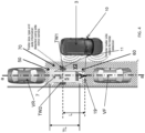
- Figure 4 shows the trailer 5 parked between two vehicles VF, VR.
- the vehicle 3 is equipped with a trailer parameter identification system 1 and is shown in Figure 4 while performing a trailer identification manoeuvre to identify three geometrical parameters relating to the trailer 5: the trailer hitch length L, the number of axles of the trailer 5, and the trailer maximum length TL.
- a rear end portion 50 of the trailer 5 enters the field of view of the camera 11 mounted on the right hand mirror 15 of the vehicle 3.
- the camera 11 therefore acquires an image, and the image is sent to the camera processor 33A via a data communication channel (not shown).
- the camera processor 33A is configured to identify the rear end portion 50 of the trailer 5 and to generate at least one value related to the position of the rear end portion 50 of the trailer 5.
- said value is a reference coordinate of the rear end portion 50 of the trailer 5 along axis a-a shown in Figure 4 .
- the axis a-a corresponds to a longitudinal axis of the trailer 5.
- a wheel portion 70 of the trailer 5 enters the field of view V3 of the camera 11.
- the camera 11 acquires an image, and the image is sent to the camera processor 33A via the data communication channel.
- the camera processor 33A is configured to identify said wheel portion 70 and to generate an axle count related to the presence in the trailer 5 of said first axle 7.
- a similar procedure is repeated for detecting further trailer axles, if present. In the described embodiment, a single axle is detected and counted.
- the trailer parameter identification system could alternatively be configured to identify a tyre portion of the trailer.
- the camera processor 33A is configured to identify the front end portion 60 of the trailer 5 and to generate a second value related to the position of the front end 60 of the trailer 5.
- said value represents the coordinate of said front end 60 of the trailer 5 along axis a-a of Figure 4 relative to the reference coordinate assigned by the camera processor 33A to the rear end portion 50 of the trailer 5.
- the camera processor 33A is thus also configured to calculate the maximum length TL of the trailer 5 as the difference between the two measured values. In the described embodiment, the trailer length is calculated as about 3 metres.
- the tow coupler 19 of the trailer 5 enters the data acquisition domain of the right hand radar system 7A.
- the radar system 7A acquires data and the data are sent to the radar processor 33B via a communication channel (not shown).
- the radar processor 33B is configured to identify the position of the tow coupler 19 and of the wheel axle 7. The identification is based on reflected electromagnetic energy.
- the radar processor 33B can thus calculate the hitch length L of the trailer 5. In the described embodiment, the hitch length L of the trailer 5 corresponds to about 2 metres.
- the geometrical parameters of the trailer 5 can be determined with reference to the distance travelled by the vehicle 3 as it travels past the trailer 5.
- the distance travelled by the vehicle 3 between the identified trailer features can be determined by appropriate vehicle measurements, for example the number of rotations (full or partial) of the vehicle wheels W1-W4.
- the distance travelled by the vehicle 3 could be determined based on coordinates derived from an on-board global positioning system (GPS).
- GPS global positioning system
- the processors 33A and 33B are further configured to optionally cooperate to identify the trailer type.
- the results obtained by processing the data acquired by the cameras 9, 10, 11 and by the radar systems 7A, 7B are used in the trailer type identification process.
- the trailer parameter identification system 1 has identified the following attribute relating to the trailer 5: the trailer 5 is a trailer for transporting motorcycles. This identification was possible on the basis that the trailer parameter identification system 1 identified a single axle 7, a trailer length TL of about 3 metres, and a hitch length of 2 metres.
- a similar procedure would be carried out if the trailer was located on the left hand side of the vehicle, by using the left hand camera 10 and radar system 7B instead of using the right hand camera 9 and radar system 7A.
- the rear view camera 9 can be used to detect and assess a trailer located at the back of the vehicle 3.
- An alternate embodiment of the system 1 utilises a combination of a side view camera and one or more side ultrasonic sensors disposed on each side of the vehicle 3.
- the side ultrasonic sensors can identify the location of the back of the trailer 5.
- the system 1 can be configured to implement a shape recognition algorithm to identify a trailer wheel TW1, TW2 in an image data set derived from the side view camera.
- the system 1 can also determine the maximum height of the trailer 5 based on said image data set. If no further trailer wheels TW1, TW2 are identified using the side camera, the system 1 can use the side ultrasonic sensor(s) to detect the front of the trailer body.
- the side camera can then be used to identify the tow coupling 19.
- the system could be configured to reverse the procedure to allow the trailer features to be identified as the vehicle 3 travels from the front to the rear of the trailer 5.
- the system 1 could, for example, utilise said shape recognition algorithm automatically to identify the front and rear of the trailer 5, for example by detecting the presence/absence of the tow coupling 19 or the hitch frame 21.
- the driver of the vehicle 3 could indicate the direction in which they are travelling in relation to the trailer 5.
- This embodiment could be developed to measure the posture (attitude) of the trailer and/or the ride height of the trailer, for example to determine loading of the trailer to identify any possible imbalance and tyre pressure issues.
- the implementation of a suitable shape recognition algorithm would allow the side view camera to be used without the side ultrasonic sensors.
Description
- The present disclosure relates to a trailer parameter identification system for identifying at least one geometrical parameter relating to a trailer. The present disclosure also relates to a vehicle; to a method; and to a computer program product.
- It is known to provide a vehicle with parking sensors associated with a park aid system. The parking sensors detect the presence of an obstacle during a parking manoeuvre and the park aid system informs the driver accordingly.
- It is known to provide a vehicle with an electronic power assisted steering system (EPAS). The EPAS uses image data acquired from a video camera and/or obstacle proximity data acquired by parking sensors to calculate a parking trajectory and then generates a set of steering control signals to automatically control the vehicle during a parking manoeuvre.
- It is known from
GB 2447672 - It is known from
WO 2013/086249 to provide a vehicle vision system having a plurality of cameras with respective fields of view exterior of a vehicle. The vehicle system is configured to generate a 360° view around the vehicle. Cameras may be mounted on a trailer which may optionally be incorporated into the 360° view generated by the vision system. -
US2011/0013201A1 discloses a device for measuring a parking space as a vehicle drives past the parking space, the device including a depth-measuring line scan camera movable together with the vehicle for acquiring individual images of the environment surrounding the vehicle transverse to a longitudinal direction of the vehicle and an arrangement for acquiring the movement of the vehicle. The individual images of the environment surrounding the vehicle contain depth information that is resolvable in a vertical direction. - A target trailer route may depend on certain trailer geometrical parameters, such as trailer length, hitch length, axle number and trailer wheelbase. Typically, the driver manually enters in the on-board computing unit the values of any required trailer geometrical parameters, or he can manually select them from a look-up table. The look-up table, in certain instances, contains a list of different types of trailers and the driver is required to manually identify the trailer type from the list. The information entered by the driver could be inaccurate, or incorrect, and this could result into the calculation of an inaccurate, incorrect or at least not ideal target trailer route. The present invention was conceived in order to address this problem.
- It is an object of the present invention to reduce, or eliminate, the risk that an inaccurate, incorrect or at least not ideal target trailer route be calculated on the basis of inaccurate or erroneous information entered by the driver on a vehicle computing system configured to calculate a target trailer route.
- Aspects of the present invention relate to a trailer parameter identification system for identifying at least one geometrical parameter relating to a trailer; to a vehicle; to a method; and to a computer program product as claimed in the appended claims.
- According to an aspect of the present invention, there is provided a system for identifying at least one geometrical parameter of a trailer having a tow coupler and one or more wheel axle, the system comprising:
- a processor, and
- at least one sensor for acquiring data relating to the trailer and arranged to send said data to the processor, the at least one sensor being incorporated into a vehicle,
- wherein the processor is configured to process said data to identify the at least one geometrical parameter of the trailer with reference to a distance travelled by the vehicle as it travels past the trailer;
- the processor being configured to process said data to identify the position of the tow coupler and the one or more wheel axle to generate a value representative of at least one geometrical parameter of the trailer, the at least one geometrical parameter comprising a hitch length of the trailer.
- The identification of the at least one geometrical parameter relating to the trailer may thus be performed by the processor on the basis of the data relating to the trailer acquired by the at least one sensor.
- The value generated as part of the method is representative of a geometrical parameter relating to the trailer. For example, the value may be: a number indicating distance measured in units of length; or a number indicating an area, a volume, or an angle. This list is not exhaustive and the value may take other forms and be related to other geometrical parameters. For example, the value could be a number indicating the number of wheels on the trailer, or a set of numbers indicating the trailer's shape or profile.
- The at least one geometrical parameter can comprise one or more of the following: a tow bar position; a length of the trailer, such as a maximum length of the trailer; a rear overhang of the trailer; a width of the trailer, such as a maximum width of the trailer; a height of the trailer, such as a maximum height of the trailer; a height of a trailer undercarriage or chassis; a trailer type or shape; the trailer attitude; and the number of wheels.
- The at least one geometrical parameter can comprise the number of axles of the trailer. If the trailer has more than one axle, the wheelbase of the trailer is the distance between the outermost axles.
- In some embodiments, the processor is configured to generate a descriptive result related to the trailer. Said descriptive result can be associated with a shape of the trailer, or with a type, class or category of the trailer. Said descriptive result can be a string of alphanumeric characters.
- The at least one sensor functions as a data acquisition means. The at least one sensor may comprise at least one scanning device. The at least one sensor may comprise a sensing means arranged to scan a surface external to the vehicle. The at least one sensor can comprise an imaging sensor, such as a camera; a radar system such as a side scanning radar; a lidar system; a vehicle parking sensor; an ultrasonic transceiver; or a laser scanner. This list, however, is not exhaustive. A combination of different types of sensors can be utilised, for example the at least one sensor can comprise at least one camera and one or more ultrasonic transceivers. The sensors can be configured to acquire data from one or both sides of the vehicle. For example, a sensor can be side facing.
- In some embodiments, the trailer parameter identification system is adapted to be installed on-board a vehicle. Said vehicle can, for example, be a car, a van, an SUV, a truck or a bus. According to another aspect of the present invention there is provided a vehicle comprising a trailer parameter identification system as described herein. Said vehicle can be a trailer towing vehicle.
- The vehicle can further comprise a GPS system, and the GPS system can be configured to cooperate with the trailer parameter identification system in order to associate at least one GPS coordinate to the trailer. If the trailer is parked at a trailer parking location, said GPS coordinate can be a GPS coordinate of the trailer parking location. Said GPS coordinate can be stored and used later to retrieve the parking location of the trailer, if necessary. Alternatively, said GPS coordinate can be a GPS coordinate associated with the location of the vehicle, which location would be an approximation of the trailer location when the vehicle is next to, or close to, the trailer.
- The trailer parameter identification system can be in the form of a trailer parameter identification apparatus. The trailer parameter identification apparatus can comprise one or more computational devices, such as said processor.
- According to a further aspect of the present invention there is provided a method of identifying at least one geometrical parameter of a trailer having a tow coupler and one or more wheel axle, the method comprising:
- acquiring data relating to the trailer from at least one sensor and arranging to send said data to a processor, the at least one sensor being incorporated into a vehicle; and
- processing said data to identify the at least one geometrical parameter of the trailer with reference to a distance travelled by the vehicle as it travels past the trailer;
- wherein processing said data comprises identifying the position of the tow coupler and the one or more wheel axle to generate a value representative of at least one geometrical parameter of the trailer, the at least one geometrical parameter comprising a hitch length of the trailer.
- The at least one sensor and/or the processor is incorporated into a vehicle. The method can thus further comprise moving the vehicle alongside the trailer. The method can comprise driving the vehicle past the trailer. The distance travelled by the vehicle can be measured, for example by wheel rotation sensors, thereby enabling the processor to generate said geometrical parameter relating to the trailer.
- According to a further aspect of the present invention there is provided a computer program product for configuring or reconfiguring a vehicle system having at least one sensor and a processor, the computer program product comprising a computer readable storage medium including computer readable program code, wherein the computer readable program code, when executed on the vehicle system, configures or reconfigures the vehicle system for performing a method as described herein.
- The at least one sensor may be configured to automatically commence the acquisition process, for example when a predetermined portion of the trailer is located within a spatial data acquisition domain defined by the at least one sensor, or the data acquisition process may be manually triggered by a user.
- The at least one sensor may be configured to acquire a reference data set when the trailer is outside the spatial data acquisition domain. The trailer parameter identification system may thus be configured to be able to identify that the trailer is not located in the spatial data acquisition domain over which the sensor operates. The reference data may be used as the basis of a calibration procedure to train the trailer parameter identification system to automatically detect the trailer, or any given portion thereof, when the trailer is located within the spatial data acquisition domain and commence the data acquisition process.
- The sensor may be configured to scan over a direction or over an area. For example the at least one sensor may be mounted on a rotatable shaft actuated by an electric motor.
- The trailer parameter identification system may comprise two or more sensors, and said two or more sensors may be configured to cooperate. For example, said two or more sensors may be configured to simultaneously acquire the data relating to the trailer. The two or more sensors can be the same or different from each other.
- The method(s) described herein can each be computer-implemented, for example on a computational apparatus comprising one or more microprocessors. According to a yet further aspect of the present invention there is provided a computer program product comprising a computer readable storage medium including computer readable program code, where the computer readable program code when executed on a computer causes the computer to perform the method(s) described herein.
- The term processor used herein is to be understood as covering both single processors and multiple processors. For example, the processing steps described herein could be performed by a single processor; or could be performed by separate processors.
- An embodiment of the present invention will now be described, by way of example only, with reference to the accompanying figures, in which:
-
Figure 1 illustrates schematically a vehicle and a trailer with some associated dimensions, parameters and nomenclature; -
Figure 2 is a plan view of a trailer coupled to a vehicle incorporating a trailer parameter identification system in accordance with an embodiment of the present invention; -
Figure 3 shows schematically the vehicle and the trailer parameter identification system ofFigure 2 ; and -
Figure 4 is a plan view of the vehicle incorporating the trailer parameter identification system ofFigure 2 while performing a trailer parameter identification operation. -
Figure 1 schematically shows avehicle 3 and a trailer 5 connected thereto (thevehicle 3 and the trailer 5, when coupled, are said to form a `rig'). Thevehicle 3 comprises forward steerable wheels W1, W2 and rear non-steerable wheels W3, W4. The trailer has asingle axle 7 arranged between non-steerable trailer wheels TW1 and TW2. - The
vehicle 3 is equipped with a trailer parameter identification system 1 for identifying geometrical parameters relating to the trailer 5. Thevehicle 3 is also equipped with a vehicle control system (not shown). In the described embodiment, the geometrical parameters identified by the trailer parameter identification system 1 are passed to the vehicle control system to assist the vehicle control system with reversing thevehicle 3 and the trailer 5 into a parking space. - This paragraph explains in more detail the requirement of providing the vehicle control system with information relating to certain geometrical parameters relating to the trailer 5. As shown in
Figure 1 , it is possible to define a hitch angle Φ between thevehicle 3 and the trailer 5 according to the following set of equations:


- R is the turning radius of the `rig' (i.e. of the
vehicle 3 and trailer 5); - θ is the steering angle of the
vehicle 3; - d is the wheelbase of the
vehicle 3; - h is the tow bar offset of the
vehicle 3; and - L is the hitch length of the trailer 5;
- The vehicle control system, comprises a trailer guidance module (not shown) which can output a maximum hitch angle signal to indicate the maximum permissible hitch angle ΦMAX for the current steering angle θ. The wheelbase of the vehicle d, the tow bar offset of the vehicle h and the steering angle θ are parameters defined for the
vehicle 3. The hitch length L is instead a parameter defined for the trailer 5. Therefore, the vehicle control system requires the driver to input manually a value for the hitch length L. If the driver does not have the required information to hand, the driver may have to take a manual measurement of the hitch length L, e.g. by using a tape measure, and then enter it in an on-board computer unit provided in thevehicle 3 so that the driver can pass the required information to the vehicle control system as part of a manual trailer setup operation. On the basis of the information provided by the driver, the vehicle control system will be able to generate a steering angle control signal and output it to an electronic power assisted steering module (not shown) to control the angle of asteering wheel 47 to provide a required steering angle θ for the front wheels W1, W2. The electronic power assisted module automatically adjusts the angular orientation of thesteering wheel 47 to provide the appropriate steering angle θ at the front wheels W1, W2 to control thevehicle 3 and the trailer 5 to match the actual trailer travel direction TACT with a target trailer travel direction (not shown). The vehicle control system may likewise require inputting of further geometrical parameters relating to the trailer in order to optimise the automatic rig parking manoeuvres, e.g. the trailer length TL and the trailer number of axles. - The trailer parameter identification system 1 described herein comprises: a plurality of sensors in the form of left and
right side cameras vehicle 3; arear camera 9, mounted on a rear end of thevehicle 3; and left andright radar systems vehicle 3. Thecameras radars central processing unit 33 via appropriate data transfer channels (not shown). Thecentral processing unit 33 comprises twoprocessors sensors - The
vehicle cameras vehicle 3. Thecameras radar systems systems - It should be noted that in the present embodiment each of the sensors (the
cameras radar systems radar systems vehicle 3, and thecameras - A
tow hitch 17 is mounted to thevehicle 3 for coupling to atrailer tow coupler 19 mounted to the trailer 5. Thetow hitch 17 is an upwardly projecting tow ball in the present embodiment. Thetrailer tow coupler 19 is mounted to atrailer hitch frame 21 disposed at the front of the trailer 5. Thehitch frame 21 is an A-frame having a front apex 23 to which the trailer coupler is mounted. - The
central processing unit 33 comprises acamera processor 33A configured to process the image data acquired from thecameras vehicle cameras camera processor 33A for analysis. In use, thecamera processor 33A analyses the image data from thevehicle cameras Figure 4 . Similarly, thecentral processing unit 33 comprises aradar processor 33B configured to process the radar data acquired by theradar systems - The captured image and radar data are processed to generate different sets of post-processed data. In the described embodiment, the image data are processed to retrieve the trailer length TL and the axle number, and the radar data are processed to retrieve the axle number and the trailer hitch length L. The image and radar data are used in combination to determine the trailer type. The captured image and radar data are used to achieve independent estimates of the axle number, one obtained from the data acquired by the cameras and one obtained from the data acquired by the radar systems.
- It will be apparent to the skilled person that various identification algorithms, methods or techniques can be used to detect the trailer 5, or any part or portion thereof, when the trailer 5 enters the field of views V1, V2, V3 of any of the
cameras vehicle 3. For example, the identification algorithm could specify that a predetermined marker mounted on the trailer 5, e.g. a yellow circle, be identified by the trailer parameter identification system 1. Another possible identification technique is based on sound pulses generated by an ultrasonic probe: when energy is reflected back by the trailer, the probe will have detected the presence of the trailer. - Further, once the trailer or any part thereof has been detected, it will be apparent to the skilled person that various algorithms, methods or techniques can be used to process the acquired data to generate values relating to a geometrical parameter of the trailer.
- With reference to
Figure 4 , an example of a trailer identification operation carried out using a trailer parameter identification system 1 of the type described above will now be described in detail:
Figure 4 shows the trailer 5 parked between two vehicles VF, VR. Thevehicle 3 is equipped with a trailer parameter identification system 1 and is shown inFigure 4 while performing a trailer identification manoeuvre to identify three geometrical parameters relating to the trailer 5: the trailer hitch length L, the number of axles of the trailer 5, and the trailer maximum length TL. - As the
vehicle 3 approaches the parking bay at which the trailer 5 is parked, arear end portion 50 of the trailer 5 enters the field of view of thecamera 11 mounted on theright hand mirror 15 of thevehicle 3. Thecamera 11 therefore acquires an image, and the image is sent to thecamera processor 33A via a data communication channel (not shown). Thecamera processor 33A is configured to identify therear end portion 50 of the trailer 5 and to generate at least one value related to the position of therear end portion 50 of the trailer 5. In the described embodiment, said value is a reference coordinate of therear end portion 50 of the trailer 5 along axis a-a shown inFigure 4 . The axis a-a corresponds to a longitudinal axis of the trailer 5. - As the
vehicle 3 moves forwards along a trajectory parallel to the axis a-a ofFigure 4 , at a certain time awheel portion 70 of the trailer 5 (i.e. a portion of the trailer associated with the presence in the trailer 5 of a first axle 7) enters the field of view V3 of thecamera 11. Thecamera 11 acquires an image, and the image is sent to thecamera processor 33A via the data communication channel. Thecamera processor 33A is configured to identify saidwheel portion 70 and to generate an axle count related to the presence in the trailer 5 of saidfirst axle 7. A similar procedure is repeated for detecting further trailer axles, if present. In the described embodiment, a single axle is detected and counted. The trailer parameter identification system could alternatively be configured to identify a tyre portion of the trailer. - As the
vehicle 3 moves forwards, afront end portion 60 of the trailer 5 enters the field of view of thecamera 11. Thecamera processor 33A is configured to identify thefront end portion 60 of the trailer 5 and to generate a second value related to the position of thefront end 60 of the trailer 5. In the described embodiment, said value represents the coordinate of saidfront end 60 of the trailer 5 along axis a-a ofFigure 4 relative to the reference coordinate assigned by thecamera processor 33A to therear end portion 50 of the trailer 5. Thecamera processor 33A is thus also configured to calculate the maximum length TL of the trailer 5 as the difference between the two measured values. In the described embodiment, the trailer length is calculated as about 3 metres. - As the
vehicle 3 moves forwards, at a certain time thetow coupler 19 of the trailer 5 enters the data acquisition domain of the righthand radar system 7A. Theradar system 7A acquires data and the data are sent to theradar processor 33B via a communication channel (not shown). Theradar processor 33B is configured to identify the position of thetow coupler 19 and of thewheel axle 7. The identification is based on reflected electromagnetic energy. Theradar processor 33B can thus calculate the hitch length L of the trailer 5. In the described embodiment, the hitch length L of the trailer 5 corresponds to about 2 metres. - The geometrical parameters of the trailer 5 can be determined with reference to the distance travelled by the
vehicle 3 as it travels past the trailer 5. The distance travelled by thevehicle 3 between the identified trailer features can be determined by appropriate vehicle measurements, for example the number of rotations (full or partial) of the vehicle wheels W1-W4. Alternatively, or in addition, the distance travelled by thevehicle 3 could be determined based on coordinates derived from an on-board global positioning system (GPS). - The
processors cameras radar systems single axle 7, a trailer length TL of about 3 metres, and a hitch length of 2 metres. - A similar procedure would be carried out if the trailer was located on the left hand side of the vehicle, by using the
left hand camera 10 andradar system 7B instead of using theright hand camera 9 andradar system 7A. Similarly, therear view camera 9 can be used to detect and assess a trailer located at the back of thevehicle 3. - An alternate embodiment of the system 1 utilises a combination of a side view camera and one or more side ultrasonic sensors disposed on each side of the
vehicle 3. When activated, the side ultrasonic sensors can identify the location of the back of the trailer 5. The system 1 can be configured to implement a shape recognition algorithm to identify a trailer wheel TW1, TW2 in an image data set derived from the side view camera. The system 1 can also determine the maximum height of the trailer 5 based on said image data set. If no further trailer wheels TW1, TW2 are identified using the side camera, the system 1 can use the side ultrasonic sensor(s) to detect the front of the trailer body. The side camera can then be used to identify thetow coupling 19. The system could be configured to reverse the procedure to allow the trailer features to be identified as thevehicle 3 travels from the front to the rear of the trailer 5. The system 1 could, for example, utilise said shape recognition algorithm automatically to identify the front and rear of the trailer 5, for example by detecting the presence/absence of thetow coupling 19 or thehitch frame 21. Alternatively, the driver of thevehicle 3 could indicate the direction in which they are travelling in relation to the trailer 5. This embodiment could be developed to measure the posture (attitude) of the trailer and/or the ride height of the trailer, for example to determine loading of the trailer to identify any possible imbalance and tyre pressure issues. The implementation of a suitable shape recognition algorithm would allow the side view camera to be used without the side ultrasonic sensors. - It will be apparent to the skilled person that many variations of the invention are possible, within the scope of the appended claims.
Claims (13)
- A system (1) for identifying at least one geometrical parameter of a trailer (5) having a tow coupler (19) and one or more wheel axle (7), the system comprising:a processor (33), andat least one sensor for acquiring data relating to the trailer (5) and arranged to send said data to the processor (33), the at least one sensor being incorporated into a vehicle (3),wherein the processor (33) is configured to process said data to identify the at least one geometrical parameter of the trailer (5) with reference to a distance travelled by the vehicle (3) as it travels past the trailer (5);the processor (33) being configured to process said data to identify the position of the tow coupler (19) and the one or more wheel axle (7) to generate a value representative of at least one geometrical parameter of the trailer (5), the at least one geometrical parameter comprising a hitch length (L) of the trailer (5).
- A system according to claim 1, wherein said at least one geometrical parameter comprises one or more of the following:a tow bar position;a maximum length of the trailer (TL);a rear overhang of the trailer;trailer shape; andnumber of wheels.
- A system according to claim 1 or claim 2, wherein said at least one geometrical parameter comprises the number of axles of the trailer (5).
- A system according to any one of claims 1, 2 or 3, wherein said at least one geometrical parameter comprises a height of the trailer (5).
- A system according to any one of the previous claims, wherein the processor (33) is configured to process said data to generate a descriptive result related to the trailer (5).
- A system according to claim 5, wherein said descriptive result is associated with a shape of the trailer (5).
- A system according to claim 5, wherein said descriptive result is associated with a type, class or category of the trailer (5).
- A system according to any one of the previous claims, wherein the at least one sensor is: a camera; a radar; a vehicle parking sensor; an ultrasonic transceiver; or a laser scanner.
- A system according to one of the previous claims, wherein said trailer parameter identification system (1) is adapted to be installed on-board a vehicle (3).
- A vehicle (3) comprising a system according to claim 9.
- A vehicle according to claim 10, comprising a GPS system configured to cooperate with the system in order to associate at least one GPS coordinate to the trailer (5).
- A method of identifying at least one geometrical parameter of a trailer (5) having a tow coupler (19) and one or more wheel axle (7), the method comprising:acquiring data relating to the trailer (5) from at least one sensor and arranging to send said data to a processor (33), the at least one sensor being incorporated into a vehicle (3); andprocessing said data to identify the at least one geometrical parameter of the trailer (5) with reference to a distance travelled by the vehicle (3) as it travels past the trailer (5);wherein processing said data comprises identifying the position of the tow coupler (19) and the one or more wheel axle (7) to generate a value representative of at least one geometrical parameter of the trailer, the at least one geometrical parameter comprising a hitch length (L) of the trailer (5).
- A computer program product for configuring or reconfiguring a vehicle system having a at least one sensor and a processor, the computer program product comprising a computer readable storage medium including computer readable program code, wherein the computer readable program code, when executed on the vehicle system, configures or reconfigures the vehicle system for performing a method according to claim 12.
Applications Claiming Priority (2)
| Application Number | Priority Date | Filing Date | Title |
|---|---|---|---|
| GBGB1312038.1A GB201312038D0 (en) | 2013-07-04 | 2013-07-04 | Trailer parameter identification system |
| PCT/EP2014/064268 WO2015001065A1 (en) | 2013-07-04 | 2014-07-03 | Trailer parameter identification system |
Publications (2)
| Publication Number | Publication Date |
|---|---|
| EP3017426A1 EP3017426A1 (en) | 2016-05-11 |
| EP3017426B1 true EP3017426B1 (en) | 2023-09-13 |
Family
ID=49033346
Family Applications (1)
| Application Number | Title | Priority Date | Filing Date |
|---|---|---|---|
| EP14735956.6A Active EP3017426B1 (en) | 2013-07-04 | 2014-07-03 | Trailer parameter identification system |
Country Status (4)
| Country | Link |
|---|---|
| US (1) | US10119812B2 (en) |
| EP (1) | EP3017426B1 (en) |
| GB (2) | GB201312038D0 (en) |
| WO (1) | WO2015001065A1 (en) |
Families Citing this family (114)
| Publication number | Priority date | Publication date | Assignee | Title |
|---|---|---|---|---|
| GB2447672B (en) | 2007-03-21 | 2011-12-14 | Ford Global Tech Llc | Vehicle manoeuvring aids |
| US10196088B2 (en) | 2011-04-19 | 2019-02-05 | Ford Global Technologies, Llc | Target monitoring system and method |
| US9683848B2 (en) | 2011-04-19 | 2017-06-20 | Ford Global Technologies, Llc | System for determining hitch angle |
| US9513103B2 (en) | 2011-04-19 | 2016-12-06 | Ford Global Technologies, Llc | Hitch angle sensor assembly |
| US9555832B2 (en) | 2011-04-19 | 2017-01-31 | Ford Global Technologies, Llc | Display system utilizing vehicle and trailer dynamics |
| US9723274B2 (en) | 2011-04-19 | 2017-08-01 | Ford Global Technologies, Llc | System and method for adjusting an image capture setting |
| US9854209B2 (en) | 2011-04-19 | 2017-12-26 | Ford Global Technologies, Llc | Display system utilizing vehicle and trailer dynamics |
| US9434414B2 (en) | 2011-04-19 | 2016-09-06 | Ford Global Technologies, Llc | System and method for determining a hitch angle offset |
| US9926008B2 (en) | 2011-04-19 | 2018-03-27 | Ford Global Technologies, Llc | Trailer backup assist system with waypoint selection |
| GB201312038D0 (en) * | 2013-07-04 | 2013-08-21 | Jaguar Land Rover Ltd | Trailer parameter identification system |
| GB2515800B (en) | 2013-07-04 | 2017-06-07 | Jaguar Land Rover Ltd | Vehicle control system |
| GB2552282B (en) | 2013-07-04 | 2021-03-31 | Jaguar Land Rover Ltd | Vehicle control system |
| US9963004B2 (en) | 2014-07-28 | 2018-05-08 | Ford Global Technologies, Llc | Trailer sway warning system and method |
| US9517668B2 (en) | 2014-07-28 | 2016-12-13 | Ford Global Technologies, Llc | Hitch angle warning system and method |
| US9533683B2 (en) | 2014-12-05 | 2017-01-03 | Ford Global Technologies, Llc | Sensor failure mitigation system and mode management |
| US9607242B2 (en) | 2015-01-16 | 2017-03-28 | Ford Global Technologies, Llc | Target monitoring system with lens cleaning device |
| US9522699B2 (en) | 2015-02-05 | 2016-12-20 | Ford Global Technologies, Llc | Trailer backup assist system with adaptive steering angle limits |
| US9616923B2 (en) | 2015-03-03 | 2017-04-11 | Ford Global Technologies, Llc | Topographical integration for trailer backup assist system |
| US9910151B2 (en) | 2015-03-19 | 2018-03-06 | Delphi Technologies, Inc. | Radar object detection system |
| US9804022B2 (en) | 2015-03-24 | 2017-10-31 | Ford Global Technologies, Llc | System and method for hitch angle detection |
| US9821845B2 (en) | 2015-06-11 | 2017-11-21 | Ford Global Technologies, Llc | Trailer length estimation method using trailer yaw rate signal |
| US10611407B2 (en) | 2015-10-19 | 2020-04-07 | Ford Global Technologies, Llc | Speed control for motor vehicles |
| US10384607B2 (en) | 2015-10-19 | 2019-08-20 | Ford Global Technologies, Llc | Trailer backup assist system with hitch angle offset estimation |
| US9836060B2 (en) | 2015-10-28 | 2017-12-05 | Ford Global Technologies, Llc | Trailer backup assist system with target management |
| US10017115B2 (en) | 2015-11-11 | 2018-07-10 | Ford Global Technologies, Llc | Trailer monitoring system and method |
| US9895945B2 (en) | 2015-12-08 | 2018-02-20 | Ford Global Technologies, Llc | Trailer backup assist system with hitch assist |
| US9610975B1 (en) * | 2015-12-17 | 2017-04-04 | Ford Global Technologies, Llc | Hitch angle detection for trailer backup assist system |
| US9827818B2 (en) | 2015-12-17 | 2017-11-28 | Ford Global Technologies, Llc | Multi-stage solution for trailer hitch angle initialization |
| US9798953B2 (en) | 2015-12-17 | 2017-10-24 | Ford Global Technologies, Llc | Template matching solution for locating trailer hitch point |
| US10011228B2 (en) | 2015-12-17 | 2018-07-03 | Ford Global Technologies, Llc | Hitch angle detection for trailer backup assist system using multiple imaging devices |
| US10127459B2 (en) | 2015-12-17 | 2018-11-13 | Ford Global Technologies, Llc | Trailer type identification system |
| US9796228B2 (en) * | 2015-12-17 | 2017-10-24 | Ford Global Technologies, Llc | Hitch angle detection for trailer backup assist system |
| US9934572B2 (en) | 2015-12-17 | 2018-04-03 | Ford Global Technologies, Llc | Drawbar scan solution for locating trailer hitch point |
| US10155478B2 (en) | 2015-12-17 | 2018-12-18 | Ford Global Technologies, Llc | Centerline method for trailer hitch angle detection |
| US10005492B2 (en) | 2016-02-18 | 2018-06-26 | Ford Global Technologies, Llc | Trailer length and hitch angle bias estimation |
| EP3244233B1 (en) * | 2016-05-10 | 2022-02-23 | Continental Automotive GmbH | Apparatus and method for automated parking |
| US10106193B2 (en) | 2016-07-01 | 2018-10-23 | Ford Global Technologies, Llc | Enhanced yaw rate trailer angle detection initialization |
| US10393862B2 (en) | 2016-07-07 | 2019-08-27 | Aptiv Technologies Limited | Trailer estimation with elevation enhanced sensing |
| US10308243B2 (en) | 2016-07-26 | 2019-06-04 | Ford Global Technologies, Llc | Vehicle remote park assist with occupant detection |
| DE102016114060A1 (en) | 2016-07-29 | 2018-02-01 | Connaught Electronics Ltd. | A method of determining a geometric parameter of a trailer of a trailer with a motor vehicle and the trailer, detection system, driver assistance system and motor vehicle |
| US10481255B2 (en) | 2016-08-09 | 2019-11-19 | Aptiv Technologies Limited | Trailer dimension estimation with two dimensional radar and camera |
| US10046800B2 (en) * | 2016-08-10 | 2018-08-14 | Ford Global Technologies, Llc | Trailer wheel targetless trailer angle detection |
| US10207643B2 (en) * | 2016-09-06 | 2019-02-19 | Aptiv Technologies Limited | Camera based trailer detection and tracking |
| US10222804B2 (en) | 2016-10-21 | 2019-03-05 | Ford Global Technologies, Llc | Inertial reference for TBA speed limiting |
| US10369988B2 (en) | 2017-01-13 | 2019-08-06 | Ford Global Technologies, Llc | Autonomous parking of vehicles inperpendicular parking spots |
| US10049573B1 (en) * | 2017-04-21 | 2018-08-14 | Ford Global Technologies, Llc | Active park assist detection of semi-trailer overhang |
| US10407014B2 (en) | 2017-05-10 | 2019-09-10 | Ford Global Technologies, Llc | Vehicle underride impact detection systems and methods |
| US10683034B2 (en) | 2017-06-06 | 2020-06-16 | Ford Global Technologies, Llc | Vehicle remote parking systems and methods |
| US10585430B2 (en) | 2017-06-16 | 2020-03-10 | Ford Global Technologies, Llc | Remote park-assist authentication for vehicles |
| US10775781B2 (en) | 2017-06-16 | 2020-09-15 | Ford Global Technologies, Llc | Interface verification for vehicle remote park-assist |
| US10234868B2 (en) | 2017-06-16 | 2019-03-19 | Ford Global Technologies, Llc | Mobile device initiation of vehicle remote-parking |
| US10710585B2 (en) | 2017-09-01 | 2020-07-14 | Ford Global Technologies, Llc | Trailer backup assist system with predictive hitch angle functionality |
| US11215451B2 (en) * | 2017-09-20 | 2022-01-04 | Continental Automotive Systems, Inc. | Trailer length detection system |
| US10580304B2 (en) | 2017-10-02 | 2020-03-03 | Ford Global Technologies, Llc | Accelerometer-based external sound monitoring for voice controlled autonomous parking |
| US10281921B2 (en) | 2017-10-02 | 2019-05-07 | Ford Global Technologies, Llc | Autonomous parking of vehicles in perpendicular parking spots |
| US10657823B2 (en) * | 2017-10-26 | 2020-05-19 | Bendix Commercial Vehicle Systems Llc | System and method for determining when an object detected by a collision avoidance sensor on one member of an articulated vehicle comprises another member of the vehicle |
| GB201718176D0 (en) * | 2017-11-02 | 2017-12-20 | Jaguar Land Rover Ltd | Display method and apparatus |
| US10627811B2 (en) | 2017-11-07 | 2020-04-21 | Ford Global Technologies, Llc | Audio alerts for remote park-assist tethering |
| US10336320B2 (en) | 2017-11-22 | 2019-07-02 | Ford Global Technologies, Llc | Monitoring of communication for vehicle remote park-assist |
| US10578676B2 (en) | 2017-11-28 | 2020-03-03 | Ford Global Technologies, Llc | Vehicle monitoring of mobile device state-of-charge |
| US10955540B2 (en) | 2017-12-01 | 2021-03-23 | Aptiv Technologies Limited | Detection system |
| US10600234B2 (en) | 2017-12-18 | 2020-03-24 | Ford Global Technologies, Llc | Inter-vehicle cooperation for vehicle self imaging |
| US10417911B2 (en) | 2017-12-18 | 2019-09-17 | Ford Global Technologies, Llc | Inter-vehicle cooperation for physical exterior damage detection |
| US10583830B2 (en) | 2018-01-02 | 2020-03-10 | Ford Global Technologies, Llc | Mobile device tethering for a remote parking assist system of a vehicle |
| US11148661B2 (en) | 2018-01-02 | 2021-10-19 | Ford Global Technologies, Llc | Mobile device tethering for a remote parking assist system of a vehicle |
| US10814864B2 (en) | 2018-01-02 | 2020-10-27 | Ford Global Technologies, Llc | Mobile device tethering for a remote parking assist system of a vehicle |
| US10737690B2 (en) | 2018-01-02 | 2020-08-11 | Ford Global Technologies, Llc | Mobile device tethering for a remote parking assist system of a vehicle |
| US10585431B2 (en) | 2018-01-02 | 2020-03-10 | Ford Global Technologies, Llc | Mobile device tethering for a remote parking assist system of a vehicle |
| US10688918B2 (en) | 2018-01-02 | 2020-06-23 | Ford Global Technologies, Llc | Mobile device tethering for a remote parking assist system of a vehicle |
| US10974717B2 (en) | 2018-01-02 | 2021-04-13 | Ford Global Technologies, I.LC | Mobile device tethering for a remote parking assist system of a vehicle |
| US10684773B2 (en) | 2018-01-03 | 2020-06-16 | Ford Global Technologies, Llc | Mobile device interface for trailer backup-assist |
| US10747218B2 (en) | 2018-01-12 | 2020-08-18 | Ford Global Technologies, Llc | Mobile device tethering for remote parking assist |
| US10745005B2 (en) | 2018-01-24 | 2020-08-18 | Ford Global Technologies, Llc | Inter-vehicle cooperation for vehicle self height estimation |
| US10917748B2 (en) | 2018-01-25 | 2021-02-09 | Ford Global Technologies, Llc | Mobile device tethering for vehicle systems based on variable time-of-flight and dead reckoning |
| US10684627B2 (en) | 2018-02-06 | 2020-06-16 | Ford Global Technologies, Llc | Accelerometer-based external sound monitoring for position aware autonomous parking |
| US11188070B2 (en) | 2018-02-19 | 2021-11-30 | Ford Global Technologies, Llc | Mitigating key fob unavailability for remote parking assist systems |
| US10507868B2 (en) | 2018-02-22 | 2019-12-17 | Ford Global Technologies, Llc | Tire pressure monitoring for vehicle park-assist |
| US10732622B2 (en) | 2018-04-05 | 2020-08-04 | Ford Global Technologies, Llc | Advanced user interaction features for remote park assist |
| US10793144B2 (en) | 2018-04-09 | 2020-10-06 | Ford Global Technologies, Llc | Vehicle remote park-assist communication counters |
| US10493981B2 (en) | 2018-04-09 | 2019-12-03 | Ford Global Technologies, Llc | Input signal management for vehicle park-assist |
| US10759417B2 (en) | 2018-04-09 | 2020-09-01 | Ford Global Technologies, Llc | Input signal management for vehicle park-assist |
| US10683004B2 (en) | 2018-04-09 | 2020-06-16 | Ford Global Technologies, Llc | Input signal management for vehicle park-assist |
| US10628690B2 (en) * | 2018-05-09 | 2020-04-21 | Ford Global Technologies, Llc | Systems and methods for automated detection of trailer properties |
| US10232673B1 (en) * | 2018-06-01 | 2019-03-19 | Ford Global Technologies, Llc | Tire pressure monitoring with vehicle park-assist |
| DE102018120966A1 (en) * | 2018-08-28 | 2020-03-05 | Connaught Electronics Ltd. | Method for recognizing a part of a trailer and trailer detection system for a towing vehicle |
| US10384605B1 (en) | 2018-09-04 | 2019-08-20 | Ford Global Technologies, Llc | Methods and apparatus to facilitate pedestrian detection during remote-controlled maneuvers |
| US10845478B2 (en) * | 2018-09-07 | 2020-11-24 | GM Global Technology Operations LLC | Micro-doppler apparatus and method for trailer detection and tracking |
| US10717432B2 (en) | 2018-09-13 | 2020-07-21 | Ford Global Technologies, Llc | Park-assist based on vehicle door open positions |
| US10821972B2 (en) | 2018-09-13 | 2020-11-03 | Ford Global Technologies, Llc | Vehicle remote parking assist systems and methods |
| US10967851B2 (en) | 2018-09-24 | 2021-04-06 | Ford Global Technologies, Llc | Vehicle system and method for setting variable virtual boundary |
| US10529233B1 (en) | 2018-09-24 | 2020-01-07 | Ford Global Technologies Llc | Vehicle and method for detecting a parking space via a drone |
| US10908603B2 (en) | 2018-10-08 | 2021-02-02 | Ford Global Technologies, Llc | Methods and apparatus to facilitate remote-controlled maneuvers |
| US10838054B2 (en) | 2018-10-08 | 2020-11-17 | Aptiv Technologies Limited | Detection system and method |
| US10628687B1 (en) | 2018-10-12 | 2020-04-21 | Ford Global Technologies, Llc | Parking spot identification for vehicle park-assist |
| US11097723B2 (en) | 2018-10-17 | 2021-08-24 | Ford Global Technologies, Llc | User interfaces for vehicle remote park assist |
| US11137754B2 (en) | 2018-10-24 | 2021-10-05 | Ford Global Technologies, Llc | Intermittent delay mitigation for remote vehicle operation |
| US11077795B2 (en) | 2018-11-26 | 2021-08-03 | Ford Global Technologies, Llc | Trailer angle detection using end-to-end learning |
| US11092668B2 (en) | 2019-02-07 | 2021-08-17 | Aptiv Technologies Limited | Trailer detection system and method |
| US11789442B2 (en) | 2019-02-07 | 2023-10-17 | Ford Global Technologies, Llc | Anomalous input detection |
| US11351917B2 (en) | 2019-02-13 | 2022-06-07 | Ford Global Technologies, Llc | Vehicle-rendering generation for vehicle display based on short-range communication |
| US20200269852A1 (en) * | 2019-02-26 | 2020-08-27 | Robert Bosch Gmbh | Trailer characteristic estimation with vehicle sensors |
| US10829046B2 (en) | 2019-03-06 | 2020-11-10 | Ford Global Technologies, Llc | Trailer angle detection using end-to-end learning |
| US11195344B2 (en) | 2019-03-15 | 2021-12-07 | Ford Global Technologies, Llc | High phone BLE or CPU burden detection and notification |
| US11169517B2 (en) | 2019-04-01 | 2021-11-09 | Ford Global Technologies, Llc | Initiation of vehicle remote park-assist with key fob |
| US11275368B2 (en) | 2019-04-01 | 2022-03-15 | Ford Global Technologies, Llc | Key fobs for vehicle remote park-assist |
| KR102609872B1 (en) * | 2019-04-29 | 2023-12-06 | 엘에스엠트론 주식회사 | Apparatus for providing operation width indication of agricultural working machine |
| DE102019220526A1 (en) * | 2019-12-23 | 2021-06-24 | Robert Bosch Gesellschaft mit beschränkter Haftung | Method and device for determining at least one articulation angle of a vehicle combination |
| US11231716B2 (en) * | 2020-01-28 | 2022-01-25 | GM Global Technology Operations LLC | Method and apparatus for determining trailer dimensions in a motor vehicle |
| US11408995B2 (en) | 2020-02-24 | 2022-08-09 | Aptiv Technologies Limited | Lateral-bin monitoring for radar target detection |
| US20220072999A1 (en) * | 2020-09-09 | 2022-03-10 | GM Global Technology Operations LLC | Method and apparatus for side mirror auto adjust for trailering in a motor vehicle |
| CN112904363B (en) * | 2021-01-19 | 2023-04-25 | 北京九曜智能科技有限公司 | Method for automatically supporting hook of butt-joint trailer of automatic driving vehicle |
| EP4163133A1 (en) * | 2021-10-08 | 2023-04-12 | Bayerische Motoren Werke Aktiengesellschaft | Method for supporting during a coupling process with a trailer, computing device and assistance system for a vehicle |
| US11912348B2 (en) | 2021-10-11 | 2024-02-27 | Ford Global Technologies, Llc | Vehicle and method of profiling a trailer and determining vehicle driving range |
| DE102022200975A1 (en) * | 2022-01-31 | 2023-08-03 | Robert Bosch Gesellschaft mit beschränkter Haftung | Method and control device for determining a clutch position of a clutch of a vehicle combination |
Citations (1)
| Publication number | Priority date | Publication date | Assignee | Title |
|---|---|---|---|---|
| US20110013201A1 (en) * | 2008-01-16 | 2011-01-20 | Michael Scherl | Device and method for measuring a parking space |
Family Cites Families (59)
| Publication number | Priority date | Publication date | Assignee | Title |
|---|---|---|---|---|
| US5247442A (en) | 1991-09-25 | 1993-09-21 | Brigham Young University | Vehicular steering system for reverse paths |
| US6292094B1 (en) | 2001-01-16 | 2001-09-18 | General Motors Corporation | Vehicle-trailer backing-up control system with vehicle rear wheel steering |
| JP4754088B2 (en) | 2001-05-01 | 2011-08-24 | 本田技研工業株式会社 | Front and rear wheel steering car |
| JP2004058829A (en) | 2002-07-29 | 2004-02-26 | Aisin Seiki Co Ltd | Steering device of vehicle towing trailer |
| US6806809B2 (en) * | 2003-01-03 | 2004-10-19 | General Motors Corporation | Trailer tongue length estimation using a hitch angle sensor |
| GB0302841D0 (en) | 2003-02-07 | 2003-03-12 | Ford Global Tech Inc | Vehicle steering aids |
| DE10322828B4 (en) * | 2003-05-19 | 2007-12-20 | Daimlerchrysler Ag | Control system for a vehicle |
| DE10322829A1 (en) | 2003-05-19 | 2004-12-09 | Daimlerchrysler Ag | Control system for a vehicle |
| US6854557B1 (en) * | 2003-08-21 | 2005-02-15 | General Motors Corporation | Anti-jackknife control for vehicle-trailer backing up using rear-wheel steer control |
| DE10339075A1 (en) | 2003-08-26 | 2005-03-24 | Daimlerchrysler Ag | motor vehicle |
| US6999856B2 (en) * | 2003-08-28 | 2006-02-14 | General Motors Corporation | Trailer tongue length estimation using a trailer yaw rate sensor |
| JP3945467B2 (en) * | 2003-10-02 | 2007-07-18 | 日産自動車株式会社 | Vehicle retraction support apparatus and method |
| US7239958B2 (en) | 2003-12-18 | 2007-07-03 | General Motors Corporation | Apparatus and method for discerning a driver's intent and for aiding the driver |
| DE102004009187A1 (en) | 2004-02-25 | 2005-09-15 | Daimlerchrysler Ag | Control system for a team |
| US20050209762A1 (en) * | 2004-03-18 | 2005-09-22 | Ford Global Technologies, Llc | Method and apparatus for controlling a vehicle using an object detection system and brake-steer |
| US20050270148A1 (en) * | 2004-06-07 | 2005-12-08 | Calvin Modawell | Trailer tire monitoring system and method |
| JP4461920B2 (en) * | 2004-06-23 | 2010-05-12 | 株式会社デンソー | Parking assistance device |
| US7373224B2 (en) * | 2004-07-22 | 2008-05-13 | Safetywatch Technologies, Inc. | Brake monitoring system for heavy vehicles |
| US8036792B2 (en) | 2005-06-24 | 2011-10-11 | Renault Trucks | Method for determining a set steering angle of steered wheels of a vehicle |
| US8798860B2 (en) | 2005-06-24 | 2014-08-05 | Renault Trucks | Drive assisting method for reversal path with drawn vehicle |
| JP4432929B2 (en) | 2006-04-25 | 2010-03-17 | トヨタ自動車株式会社 | Parking assistance device and parking assistance method |
| DE102006035021B4 (en) | 2006-07-28 | 2010-04-29 | Universität Koblenz-Landau | Driver assistance device, imaging system, method and computer program device |
| US7773773B2 (en) | 2006-10-18 | 2010-08-10 | Ut-Battelle, Llc | Method and system for determining a volume of an object from two-dimensional images |
| GB2447672B (en) * | 2007-03-21 | 2011-12-14 | Ford Global Tech Llc | Vehicle manoeuvring aids |
| DE102007032720A1 (en) | 2007-07-13 | 2009-01-15 | Daimler Ag | Driver assisting method for use during shunting or parking of vehicle e.g. vehicle with trailer, involves implementing simulation for determining optimal trajectory or motion sequence of vehicle and displaying trajectory or sequence |
| US8010252B2 (en) * | 2007-10-05 | 2011-08-30 | Ford Global Technologies | Trailer oscillation detection and compensation method for a vehicle and trailer combination |
| FR2926908A1 (en) | 2008-01-30 | 2009-07-31 | Renault Sas | Motor vehicle i.e. car, driving assisting method, involves allocating quality score to each of pixels in each of corrected images, and selecting pixel having high quality in order to elaborate top view of environment of motor vehicle |
| US7777615B2 (en) * | 2008-03-20 | 2010-08-17 | Toyota Motor Engineering & Manufacturing North America, Inc. | System for assisting the attachment of a trailer to a vehicle |
| US20090271078A1 (en) * | 2008-04-29 | 2009-10-29 | Mike Dickinson | System and method for identifying a trailer being towed by a vehicle |
| US8191915B2 (en) * | 2008-10-17 | 2012-06-05 | GM Global Technology Operations LLC | Vehicle docking assistance system |
| US8068019B2 (en) * | 2008-12-23 | 2011-11-29 | Ford Global Technologies | Trailer identification system |
| DE102009002334B4 (en) * | 2009-04-09 | 2012-09-27 | Jost-Werke Gmbh | Control system with a displacement device for a fifth wheel arranged on a towing vehicle |
| FR2965785B1 (en) | 2010-10-08 | 2013-05-17 | Jtekt Europe Sas | REVERSE ASSISTANCE SYSTEM FOR A TRACKING VEHICLE WITH DIRECT WHEELS WHICH IS REACHED BY A TRACTER VEHICLE |
| WO2012103193A1 (en) | 2011-01-26 | 2012-08-02 | Magna Electronics Inc. | Rear vision system with trailer angle detection |
| US9708000B2 (en) * | 2011-04-19 | 2017-07-18 | Ford Global Technologies, Llc | Trajectory planner for a trailer backup assist system |
| US8909426B2 (en) | 2011-04-19 | 2014-12-09 | Ford Global Technologies | Trailer path curvature control for trailer backup assist |
| US9335163B2 (en) * | 2011-04-19 | 2016-05-10 | Ford Global Technologies, Llc | Trailer length estimation in hitch angle applications |
| US8930140B2 (en) | 2011-04-19 | 2015-01-06 | Ford Global Technologies, Llc | Trailer target placement assist system and method |
| US9102272B2 (en) * | 2011-04-19 | 2015-08-11 | Ford Global Technologies, Llc | Trailer target monitoring system and method |
| US9335162B2 (en) * | 2011-04-19 | 2016-05-10 | Ford Global Technologies, Llc | Trailer length estimation in hitch angle applications |
| US9164955B2 (en) | 2013-02-04 | 2015-10-20 | Ford Global Technologies | Trailer active back-up assist with object avoidance |
| US9290203B2 (en) * | 2011-04-19 | 2016-03-22 | Ford Global Technologies, Llc | Trailer length estimation in hitch angle applications |
| US9926008B2 (en) | 2011-04-19 | 2018-03-27 | Ford Global Technologies, Llc | Trailer backup assist system with waypoint selection |
| US20130006472A1 (en) | 2011-06-30 | 2013-01-03 | Continental Automotive System, Inc. | Electronic path entering for autonomous or semi-autonomous trailer backing |
| ES2659214T3 (en) * | 2011-09-13 | 2018-03-14 | Osi Optoelectronics | Enhanced laser rangefinder sensor |
| WO2013086249A2 (en) * | 2011-12-09 | 2013-06-13 | Magna Electronics, Inc. | Vehicle vision system with customized display |
| DE102011120814B4 (en) | 2011-12-10 | 2015-04-09 | Volkswagen Aktiengesellschaft | Method and device for determining an angle between a towing vehicle and a trailer coupled thereto |
| US9633566B2 (en) | 2011-12-20 | 2017-04-25 | Continental Automotive Systems, Inc. | Trailer backing path prediction using GPS and camera images |
| US8831831B2 (en) | 2011-12-20 | 2014-09-09 | Continental Automotive Systems, Inc. | Trailer backing aid using GPS mapping and camera image display |
| DE102012004440A1 (en) | 2012-03-03 | 2013-09-05 | Wabco Gmbh | Method and device for controlling the maneuvering of a vehicle combination |
| US9227474B2 (en) | 2012-06-29 | 2016-01-05 | Deere & Company | Method and system for estimating a trailer position of a trailer associated with a vehicle |
| DE102012015435A1 (en) * | 2012-08-03 | 2014-02-06 | Volkswagen Aktiengesellschaft | Method and device for maneuvering a trailer |
| US9042603B2 (en) * | 2013-02-25 | 2015-05-26 | Ford Global Technologies, Llc | Method and apparatus for estimating the distance from trailer axle to tongue |
| GB2513393B (en) | 2013-04-26 | 2016-02-03 | Jaguar Land Rover Ltd | Vehicle hitch assistance system |
| GB2552282B (en) | 2013-07-04 | 2021-03-31 | Jaguar Land Rover Ltd | Vehicle control system |
| GB2515800B (en) | 2013-07-04 | 2017-06-07 | Jaguar Land Rover Ltd | Vehicle control system |
| GB201312038D0 (en) * | 2013-07-04 | 2013-08-21 | Jaguar Land Rover Ltd | Trailer parameter identification system |
| US9440627B2 (en) * | 2014-05-28 | 2016-09-13 | Toyota Motor Engineering & Manufacturing North America, Inc. | Systems and methods for calculating trailer brake control parameters |
| US10023229B2 (en) | 2015-07-30 | 2018-07-17 | Ford Global Technologies, Llc | Multi-mode trailer backup assist interface knob |
-
2013
- 2013-07-04 GB GBGB1312038.1A patent/GB201312038D0/en not_active Ceased
-
2014
- 2014-07-03 GB GB1411930.9A patent/GB2517835B/en active Active
- 2014-07-03 EP EP14735956.6A patent/EP3017426B1/en active Active
- 2014-07-03 US US14/900,778 patent/US10119812B2/en active Active
- 2014-07-03 WO PCT/EP2014/064268 patent/WO2015001065A1/en active Application Filing
Patent Citations (1)
| Publication number | Priority date | Publication date | Assignee | Title |
|---|---|---|---|---|
| US20110013201A1 (en) * | 2008-01-16 | 2011-01-20 | Michael Scherl | Device and method for measuring a parking space |
Also Published As
| Publication number | Publication date |
|---|---|
| WO2015001065A1 (en) | 2015-01-08 |
| EP3017426A1 (en) | 2016-05-11 |
| US20160153778A1 (en) | 2016-06-02 |
| GB201411930D0 (en) | 2014-08-20 |
| GB2517835B (en) | 2018-03-14 |
| GB2517835A (en) | 2015-03-04 |
| US10119812B2 (en) | 2018-11-06 |
| GB201312038D0 (en) | 2013-08-21 |
Similar Documents
| Publication | Publication Date | Title |
|---|---|---|
| EP3017426B1 (en) | Trailer parameter identification system | |
| US10942269B2 (en) | Method for monitoring a surrounding area of a vehicle-trailer combination, monitoring device, driver assistance system and vehicle-trailer combination | |
| EP3016835B1 (en) | Vehicle control system | |
| US11400977B2 (en) | Vehicle guidance system | |
| US10875574B2 (en) | Method for operating a trailer maneuvering assistance system of a transportation vehicle and trailer maneuvering assistance system for a transportation vehicle | |
| US10035457B2 (en) | Vehicle hitch assistance system | |
| CN101332836B (en) | Trailer articulation angle system and process | |
| US20160152263A1 (en) | Vehicle Control System | |
| US20140309887A1 (en) | Trailer angle detection target plausibility | |
| US20210031795A1 (en) | Correcting a position of a vehicle with slam | |
| CN112771591B (en) | Method for evaluating the influence of an object in the environment of a vehicle on the driving maneuver of the vehicle | |
| US10744943B1 (en) | System and method for trailer alignment | |
| JP7379457B2 (en) | System and method for calibrating motion estimation algorithms using vehicle cameras | |
| CN111936375B (en) | Method and controller for determining the orientation of a trailer | |
| CN113439194A (en) | Estimating trailer characteristics using vehicle sensors | |
| US11866033B2 (en) | Method for estimating an effective length of a first vehicle segment of a vehicle combination | |
| US11952037B2 (en) | Method and apparatus in a motor vehicle for reversing multiple trailers | |
| CN218949346U (en) | Unmanned tractor | |
| CN117227838A (en) | Method and device for vehicle turning early warning and electronic equipment |
Legal Events
| Date | Code | Title | Description |
|---|---|---|---|
| PUAI | Public reference made under article 153(3) epc to a published international application that has entered the european phase |
Free format text: ORIGINAL CODE: 0009012 |
|
| 17P | Request for examination filed |
Effective date: 20160204 |
|
| AK | Designated contracting states |
Kind code of ref document: A1 Designated state(s): AL AT BE BG CH CY CZ DE DK EE ES FI FR GB GR HR HU IE IS IT LI LT LU LV MC MK MT NL NO PL PT RO RS SE SI SK SM TR |
|
| AX | Request for extension of the european patent |
Extension state: BA ME |
|
| DAX | Request for extension of the european patent (deleted) | ||
| STAA | Information on the status of an ep patent application or granted ep patent |
Free format text: STATUS: EXAMINATION IS IN PROGRESS |
|
| 17Q | First examination report despatched |
Effective date: 20161028 |
|
| STAA | Information on the status of an ep patent application or granted ep patent |
Free format text: STATUS: EXAMINATION IS IN PROGRESS |
|
| STAA | Information on the status of an ep patent application or granted ep patent |
Free format text: STATUS: EXAMINATION IS IN PROGRESS |
|
| GRAP | Despatch of communication of intention to grant a patent |
Free format text: ORIGINAL CODE: EPIDOSNIGR1 |
|
| STAA | Information on the status of an ep patent application or granted ep patent |
Free format text: STATUS: GRANT OF PATENT IS INTENDED |
|
| INTG | Intention to grant announced |
Effective date: 20230405 |
|
| P01 | Opt-out of the competence of the unified patent court (upc) registered |
Effective date: 20230528 |
|
| GRAS | Grant fee paid |
Free format text: ORIGINAL CODE: EPIDOSNIGR3 |
|
| GRAA | (expected) grant |
Free format text: ORIGINAL CODE: 0009210 |
|
| STAA | Information on the status of an ep patent application or granted ep patent |
Free format text: STATUS: THE PATENT HAS BEEN GRANTED |
|
| AK | Designated contracting states |
Kind code of ref document: B1 Designated state(s): AL AT BE BG CH CY CZ DE DK EE ES FI FR GB GR HR HU IE IS IT LI LT LU LV MC MK MT NL NO PL PT RO RS SE SI SK SM TR |
|
| REG | Reference to a national code |
Ref country code: GB Ref legal event code: FG4D |
|
| REG | Reference to a national code |
Ref country code: CH Ref legal event code: EP |
|
| REG | Reference to a national code |
Ref country code: DE Ref legal event code: R096 Ref document number: 602014088289 Country of ref document: DE |
|
| REG | Reference to a national code |
Ref country code: IE Ref legal event code: FG4D |
|
| REG | Reference to a national code |
Ref country code: LT Ref legal event code: MG9D |
|
| REG | Reference to a national code |
Ref country code: NL Ref legal event code: MP Effective date: 20230913 |
|
| PG25 | Lapsed in a contracting state [announced via postgrant information from national office to epo] |
Ref country code: GR Free format text: LAPSE BECAUSE OF FAILURE TO SUBMIT A TRANSLATION OF THE DESCRIPTION OR TO PAY THE FEE WITHIN THE PRESCRIBED TIME-LIMIT Effective date: 20231214 |
|
| PG25 | Lapsed in a contracting state [announced via postgrant information from national office to epo] |
Ref country code: SE Free format text: LAPSE BECAUSE OF FAILURE TO SUBMIT A TRANSLATION OF THE DESCRIPTION OR TO PAY THE FEE WITHIN THE PRESCRIBED TIME-LIMIT Effective date: 20230913 Ref country code: RS Free format text: LAPSE BECAUSE OF FAILURE TO SUBMIT A TRANSLATION OF THE DESCRIPTION OR TO PAY THE FEE WITHIN THE PRESCRIBED TIME-LIMIT Effective date: 20230913 Ref country code: NO Free format text: LAPSE BECAUSE OF FAILURE TO SUBMIT A TRANSLATION OF THE DESCRIPTION OR TO PAY THE FEE WITHIN THE PRESCRIBED TIME-LIMIT Effective date: 20231213 Ref country code: LV Free format text: LAPSE BECAUSE OF FAILURE TO SUBMIT A TRANSLATION OF THE DESCRIPTION OR TO PAY THE FEE WITHIN THE PRESCRIBED TIME-LIMIT Effective date: 20230913 Ref country code: LT Free format text: LAPSE BECAUSE OF FAILURE TO SUBMIT A TRANSLATION OF THE DESCRIPTION OR TO PAY THE FEE WITHIN THE PRESCRIBED TIME-LIMIT Effective date: 20230913 Ref country code: HR Free format text: LAPSE BECAUSE OF FAILURE TO SUBMIT A TRANSLATION OF THE DESCRIPTION OR TO PAY THE FEE WITHIN THE PRESCRIBED TIME-LIMIT Effective date: 20230913 Ref country code: GR Free format text: LAPSE BECAUSE OF FAILURE TO SUBMIT A TRANSLATION OF THE DESCRIPTION OR TO PAY THE FEE WITHIN THE PRESCRIBED TIME-LIMIT Effective date: 20231214 Ref country code: FI Free format text: LAPSE BECAUSE OF FAILURE TO SUBMIT A TRANSLATION OF THE DESCRIPTION OR TO PAY THE FEE WITHIN THE PRESCRIBED TIME-LIMIT Effective date: 20230913 |
|
| REG | Reference to a national code |
Ref country code: AT Ref legal event code: MK05 Ref document number: 1612057 Country of ref document: AT Kind code of ref document: T Effective date: 20230913 |
|
| PG25 | Lapsed in a contracting state [announced via postgrant information from national office to epo] |
Ref country code: NL Free format text: LAPSE BECAUSE OF FAILURE TO SUBMIT A TRANSLATION OF THE DESCRIPTION OR TO PAY THE FEE WITHIN THE PRESCRIBED TIME-LIMIT Effective date: 20230913 |
|
| PG25 | Lapsed in a contracting state [announced via postgrant information from national office to epo] |
Ref country code: IS Free format text: LAPSE BECAUSE OF FAILURE TO SUBMIT A TRANSLATION OF THE DESCRIPTION OR TO PAY THE FEE WITHIN THE PRESCRIBED TIME-LIMIT Effective date: 20240113 |
|
| PG25 | Lapsed in a contracting state [announced via postgrant information from national office to epo] |
Ref country code: AT Free format text: LAPSE BECAUSE OF FAILURE TO SUBMIT A TRANSLATION OF THE DESCRIPTION OR TO PAY THE FEE WITHIN THE PRESCRIBED TIME-LIMIT Effective date: 20230913 |