EP3017253B1 - Ceramic heat shield for a gas turbine combustion chamber, combustion chamber for a gas turbine and method - Google Patents
Ceramic heat shield for a gas turbine combustion chamber, combustion chamber for a gas turbine and method Download PDFInfo
- Publication number
- EP3017253B1 EP3017253B1 EP14771226.9A EP14771226A EP3017253B1 EP 3017253 B1 EP3017253 B1 EP 3017253B1 EP 14771226 A EP14771226 A EP 14771226A EP 3017253 B1 EP3017253 B1 EP 3017253B1
- Authority
- EP
- European Patent Office
- Prior art keywords
- heat shield
- combustion chamber
- row
- width
- increasing height
- Prior art date
- Legal status (The legal status is an assumption and is not a legal conclusion. Google has not performed a legal analysis and makes no representation as to the accuracy of the status listed.)
- Active
Links
Images
Classifications
-
- F—MECHANICAL ENGINEERING; LIGHTING; HEATING; WEAPONS; BLASTING
- F23—COMBUSTION APPARATUS; COMBUSTION PROCESSES
- F23R—GENERATING COMBUSTION PRODUCTS OF HIGH PRESSURE OR HIGH VELOCITY, e.g. GAS-TURBINE COMBUSTION CHAMBERS
- F23R3/00—Continuous combustion chambers using liquid or gaseous fuel
- F23R3/002—Wall structures
-
- F—MECHANICAL ENGINEERING; LIGHTING; HEATING; WEAPONS; BLASTING
- F02—COMBUSTION ENGINES; HOT-GAS OR COMBUSTION-PRODUCT ENGINE PLANTS
- F02C—GAS-TURBINE PLANTS; AIR INTAKES FOR JET-PROPULSION PLANTS; CONTROLLING FUEL SUPPLY IN AIR-BREATHING JET-PROPULSION PLANTS
- F02C7/00—Features, components parts, details or accessories, not provided for in, or of interest apart form groups F02C1/00 - F02C6/00; Air intakes for jet-propulsion plants
- F02C7/20—Mounting or supporting of plant; Accommodating heat expansion or creep
-
- F—MECHANICAL ENGINEERING; LIGHTING; HEATING; WEAPONS; BLASTING
- F02—COMBUSTION ENGINES; HOT-GAS OR COMBUSTION-PRODUCT ENGINE PLANTS
- F02C—GAS-TURBINE PLANTS; AIR INTAKES FOR JET-PROPULSION PLANTS; CONTROLLING FUEL SUPPLY IN AIR-BREATHING JET-PROPULSION PLANTS
- F02C7/00—Features, components parts, details or accessories, not provided for in, or of interest apart form groups F02C1/00 - F02C6/00; Air intakes for jet-propulsion plants
- F02C7/24—Heat or noise insulation
-
- F—MECHANICAL ENGINEERING; LIGHTING; HEATING; WEAPONS; BLASTING
- F23—COMBUSTION APPARATUS; COMBUSTION PROCESSES
- F23R—GENERATING COMBUSTION PRODUCTS OF HIGH PRESSURE OR HIGH VELOCITY, e.g. GAS-TURBINE COMBUSTION CHAMBERS
- F23R3/00—Continuous combustion chambers using liquid or gaseous fuel
- F23R3/007—Continuous combustion chambers using liquid or gaseous fuel constructed mainly of ceramic components
-
- F—MECHANICAL ENGINEERING; LIGHTING; HEATING; WEAPONS; BLASTING
- F23—COMBUSTION APPARATUS; COMBUSTION PROCESSES
- F23R—GENERATING COMBUSTION PRODUCTS OF HIGH PRESSURE OR HIGH VELOCITY, e.g. GAS-TURBINE COMBUSTION CHAMBERS
- F23R3/00—Continuous combustion chambers using liquid or gaseous fuel
- F23R3/42—Continuous combustion chambers using liquid or gaseous fuel characterised by the arrangement or form of the flame tubes or combustion chambers
- F23R3/60—Support structures; Attaching or mounting means
-
- F—MECHANICAL ENGINEERING; LIGHTING; HEATING; WEAPONS; BLASTING
- F05—INDEXING SCHEMES RELATING TO ENGINES OR PUMPS IN VARIOUS SUBCLASSES OF CLASSES F01-F04
- F05D—INDEXING SCHEME FOR ASPECTS RELATING TO NON-POSITIVE-DISPLACEMENT MACHINES OR ENGINES, GAS-TURBINES OR JET-PROPULSION PLANTS
- F05D2240/00—Components
- F05D2240/10—Stators
- F05D2240/15—Heat shield
-
- F—MECHANICAL ENGINEERING; LIGHTING; HEATING; WEAPONS; BLASTING
- F05—INDEXING SCHEMES RELATING TO ENGINES OR PUMPS IN VARIOUS SUBCLASSES OF CLASSES F01-F04
- F05D—INDEXING SCHEME FOR ASPECTS RELATING TO NON-POSITIVE-DISPLACEMENT MACHINES OR ENGINES, GAS-TURBINES OR JET-PROPULSION PLANTS
- F05D2300/00—Materials; Properties thereof
- F05D2300/60—Properties or characteristics given to material by treatment or manufacturing
- F05D2300/603—Composites; e.g. fibre-reinforced
- F05D2300/6033—Ceramic matrix composites [CMC]
Definitions
- the invention relates to a heat shield for a combustion chamber of a gas turbine, a combustion chamber with such a heat shield, and a method for lining a combustion chamber for a gas turbine.
- the heat shields comprise a support structure and heat shield elements which are fastened to the support structure and which cover the support structure and the combustion chamber wall from hot gases.
- the material of the heat shield elements offer ceramic materials. Ceramic materials have high temperature resistance, corrosion resistance and low thermal conductivity compared to metallic materials. But there are also known metallic heat shield elements, which are equipped with a heat protection layer. Due to material-typical thermal expansion properties and the temperature differences typically occurring during operation (ambient temperature at standstill, maximum temperature at full load), a temperature-dependent expansion of the heat shield elements must be ensured so that no component-destructive thermal stresses occur due to expansion. This can be achieved by lining the wall to be protected from hot gas attack with a plurality of individual heat shield elements which are limited in their size. Between the support structure and the individual heat shield elements, an expansion gap must be provided, which must never be completely closed for safety reasons, even in the operating state. It must be ensured that the hot gas does not over-heated the load-bearing wall structure over the expansion gap.
- the exposed surfaces of the support structure (the expansion gap) as well as protruding edges of the support structure are not optimally protected from the thermal load of the combustion chamber. This leads to thermal overloading of the support structure at these points, which must be repaired consuming. To make matters worse, that can not optimally adjust the required for the thermal expansion column due to the toleranced combustion chamber components. Due to the rough tolerance field of the components, excessively large expansion gaps occur in the gas turbine combustion chamber. This allows the hot gas to penetrate the expansion gaps and damage the metallic components. The damaged components must either be replaced or there is a grinding out of the damaged areas on the support structure with subsequent build-up welding and reworking of the affected areas into consideration. It is also possible to coat the thermally stressed sites with a ceramic protective layer or to apply a high temperature resistant alloy to thermally highly stressed components.
- the invention has for its object to provide a heat shield, a combustion chamber, and a method for lining a combustion chamber with a heat shield, with which damage to components of a combustion chamber can be avoided by hot gas injection particularly effective.
- a heat shield element to be used in the heat shield according to the invention advantageously alters the flow of a hot gas flowing in the direction across the hot side of the heat shield element, thereby counteracting hot gas introduction into the expansion gap which adjoins the heat shield element in the direction of rise.
- the rising portion of the heat shield element can shield the adjacent structures from heat radiation.
- the rise of the rising portion in the rising direction substantially extends to at least one peripheral side or to a projection extending the hot side over the cold face base.
- the rising area acts as a spoiler.
- the height of the heat shield element for example, increase only from the middle of the heat shield element.
- the altitude may or may not increase steadily.
- the rise may, for example, extend linearly up to the peripheral side or, for example, proceed continuously from a substantially linear rise to a substantially horizontal course of a projection extending the hot side over the base area of the cold side.
- the rise may also continue in the region of the projection, so that the rise extends to the peripheral side, which is adjacent to the front side of the projection on the hot side. If the rising direction is perpendicular to a peripheral surface is the height of the peripheral side in the direction of increase greater than the height of the peripheral side in the opposite direction It can be advantageously provided that the rising portion extends at least over the entire base surface of the cold side.
- the entire heat shield element is formed substantially spoiler-shaped.
- the height of the heat shield element in the rising region in the rising direction steadily, in particular linear increase.
- the rising direction has substantially perpendicular to a peripheral side of the heat shield element.
- the heat shield element on the peripheral side facing the direction of rise comprises a projection extending essentially over the width of the peripheral side, with an upper side encompassed by the hot side and an opposite lower side.
- the hot gas can additionally be prevented from penetrating into an expansion gap or damaging adjacent structures.
- Projecting edges of the combustion chamber support structure can be protected by means of the projection.
- the protrusion may have a constant height or, as a continuation of the ramp to the peripheral side, may have an ascending height of the upper side.
- a further advantageous embodiment of the invention can provide that the end face is higher than an area of the support structure adjacent to the end face and / or as heat shield elements adjoining the end face on its side facing the end face.
- At least one heat shield element according to claim 5 is formed, wherein the projection of the heat shield element projects beyond a respective adjacent region of the support structure and / or over an area of an adjacent heat shield element.
- the final ceramic row limits the area covered by the ceramic heat shield elements on one side of the covered area.
- the combustion chamber comprises a heat shield according to one of claims 1 to 7.
- the invention of a combustion chamber whose combustion chamber wall at its upstream end comprises a circumferential component, in which at least one annular groove is introduced, wherein in the groove a Combustor head end is fixed inwardly delimiting flame bottom and the heat shield with a circumferential end row adjacent to the groove to one side limiting web leaving a strain column, the rising direction of the heat shield elements of the terminal row facing the web and the web facing end side of the terminal row is higher as the adjacent area of the jetty.
- the bar is also called F-ring in silo separation chambers.
- the spoiler shape of the heat shield elements positively influences the recirculation zone of the hot gas. As a result, the penetration of the hot gas into the expansion gaps between the terminal row of the F-ring is difficult and prevents possible damage to the support structure. In addition, the spoiler shape shields the F-ring from heat radiation.
- the heat shield elements of the terminal row according to claim 5 are formed, wherein the projection projects beyond the region of the web, which extends between flame bottom and end row.
- Another object of the invention is to provide a method of lining a combustion chamber with a heat shield, wherein heat shield elements are mounted in rows leaving strain gaps between the heat shield elements on a support structure of the heat shield disposed on the combustion chamber wall of the combustion chamber. With the method damage to components of the combustion chamber can be avoided by hot gas injection particularly effective.
- the expansion gaps between the rows are adapted to a desired expansion gap width. Then, a remaining width of the gap left for the row to be arranged last is determined, and from this width, taking into account the desired expansion gap width, a desired width of the heat shield elements of the last row to be arranged is determined.
- the heat shield elements of the last row to be arranged are made according to the desired width of the heat shield elements and arranged in the gap.
- the method makes it possible to minimize the expansion gaps to a setpoint width.
- a heat shield element with excess length can be shortened to a corresponding length.
- the method according to the invention makes it possible to compensate for the length tolerances of the individual combustion chamber components. Thereby, the required expansion gaps between the rows in the combustion chamber can be reduced to a minimum, whereby the size of the exposed support structure is effectively reduced and thus shielded from the hot gas.
- the width of the gap left for the last row to be arranged is determined by provisionally lining the gap with heat shield elements of measured width and determining the width of at least one expansion column adjacent to the provisionally arranged row during operation of the combustion chamber.
- the heat shield elements can be arranged by means of the method according to claim 11 on the support structure to minimize the expansion gaps.
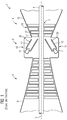
- FIG. 1 shows a schematic sectional view of a gas turbine 1 according to the prior art.
- the gas turbine 1 has inside a rotatably mounted about a rotation axis 2 rotor 3 with a shaft 4, which is also referred to as a turbine runner.
- the combustion chambers 10 each comprise a burner assembly 11 and a housing 12, which for protection against hot gases with a heat shield 20 is lined.
- the combustion chamber 10 may be, for example, an annular combustion chamber or a tube combustion chamber or a silo combustion chamber.
- the combustion system 9 communicates with an annular hot gas duct, for example.
- turbine stages connected in series form the turbine 14.
- Each turbine stage is formed of blade rings. Viewed in the flow direction of a working medium follows in the hot runner formed by a number 17 vanes row formed from blades 18 row.
- the guide vanes 17 are fastened to an inner housing of a stator 19, whereas the moving blades 18 of a row are attached to the rotor 3, for example by means of a turbine disk.
- Coupled to the rotor 3 is, for example, a generator (not shown).
- air is sucked in and compressed by the compressor 8 through the intake housing 6.
- the compressed air provided at the turbine-side end of the compressor 8 is led to the combustion system 9 where it is mixed with a fuel in the area of the burner assembly 11.
- the mixture is then burned by means of the burner assembly 11 to form a working gas stream in the combustion system 9.
- the working gas stream flows along the hot gas channel past the guide vanes 17 and the rotor blades 18.
- the working gas stream relaxes in a pulse-transmitting manner, so that the rotor blades 18 drive the rotor 3 and this drives the generator (not shown) coupled to it.
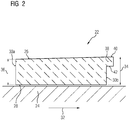
- FIG. 2 schematically shows a heat shield element 22 for use in a heat shield according to the invention, in a longitudinal section.
- the heat shield element 22 can be fastened to a support structure 24 encompassed by a heat shield.
- the heat shield element 22 has a hot side 26 which can be acted upon with hot gas and a cold side 28 which lies opposite the hot side.
- the heat shield element 22 can be fixed to the support structure 24 with the cold side 28 facing the support structure 24.
- the heat shield element 22 also comprises four peripheral sides, two of which can be seen from the opposite circumferential sides 30a, 30b in the view.
- the peripheral sides connect the cold side with the hot side.
- the heat shield element 22 has a spoiler shape and, except for a projection 38 which extends the hot side beyond the base surface of the cold side 28, is formed as a rising region, so that the height of the heat shield element increases in a direction of rise 32 over the entire length of the cold side 28.
- the heat shield element 22 is thus formed substantially spoiler-shaped.
- the height 34 of the heat shield element is greater than the height 36 of the heat shield element in the area of the at least one peripheral side 30a in the opposite direction in the region of the at least one peripheral side 30b, to which the direction of rise 32 points.
- the rising direction 32 is perpendicular to the peripheral side 30b.
- the rising portion thus extends in the rising direction 32 to the projection 38, wherein the rising portion is limited in the opposite direction from the peripheral side 30a.
- the peripheral side 30b to which the rising direction 32 points, comprises a projection 38 extending over the width of the peripheral side 30b.
- the projection 38 has a top side 40 encompassed by the hot side and an opposite bottom side 42.
- the heat shield element 22 is preferably made of a ceramic material. The height of the heat shield element increases over the entire width (the width is perpendicular to the plane) of the heat shield element in the rising direction 32 substantially over the entire length of the cold side steadily and linearly, wherein in the transition to the top of the projection, the increase steadily in the horizontal course of the top of the projection merges.
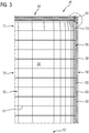
- FIG. 3 shows a highly simplified schematic section of a combustion chamber 46 according to the invention in longitudinal section.
- the combustion chamber 46 includes a combustion chamber wall 48, which defines a hot gas path 50 flowing through the combustion chamber and at its downstream end has a combustion chamber outlet 52 (not shown) which can be arranged at a turbine inlet of the gas turbine.
- the combustor At its upstream end, the combustor includes a combustor head end 54, with the combustor head end 54 including a burner assembly (not shown).
- the combustion chamber 46 is lined with a heat shield 56 for protection against hot gases.
- the heat shield 56 comprises a support structure 58 and a number of heat shield elements 60, 73, which are fastened to the support structure 58 substantially blanket, leaving expansion gaps 61.
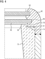
- the combustion chamber wall 48 comprises at its upstream end a circumferential component 62, said region of the combustion chamber in the FIG. 4 is shown enlarged.
- two annular grooves 64, 66 are introduced into the circumferential component 62.
- the combustion chamber head end 54 inwardly limiting flame bottom 68 is attached.
- the heat shield adjoins with a peripheral, ceramic finishing row 71 to the web 64 which delimits the groove 64 to one side, leaving an expansion gap 61.
- the heat shield elements of the terminal row 71 are formed according to the invention, wherein the direction of increase of the spoiler-shaped heat shield elements on the web 70 and the web 70 facing end face 74 of the terminal row 71 is higher than the adjacent region of the web 70th
- the web-facing peripheral side of the heat shield elements 73 has a projection 38, wherein the projection 38 projects beyond the region of the web 70, which runs between the flame bottom 68 and the end row 71.
- the heat shield elements of the heat shield 56 can be laid by means of the method according to claim 11.
Landscapes
- Engineering & Computer Science (AREA)
- Chemical & Material Sciences (AREA)
- Combustion & Propulsion (AREA)
- Mechanical Engineering (AREA)
- General Engineering & Computer Science (AREA)
- Ceramic Engineering (AREA)
- Turbine Rotor Nozzle Sealing (AREA)
Description
Die Erfindung betrifft ein Hitzeschild für eine Brennkammer einer Gasturbine, eine Brennkammer mit einem derartigen Hitzeschild, und ein Verfahren zum Auskleiden einer Brennkammer für eine Gasturbine.The invention relates to a heat shield for a combustion chamber of a gas turbine, a combustion chamber with such a heat shield, and a method for lining a combustion chamber for a gas turbine.
Die Wände von Hochtemperaturgasreaktoren, wie z.B. von unter Druck betriebenen Gasturbinen-Brennkammern, müssen mit geeigneten Abschirmungen ihrer tragenden Struktur gegen Heißgasangriff geschützt werden.The walls of high temperature gas reactors, e.g. pressurized gas turbine combustors must be protected against hot gas attack by suitable shielding of their supporting structure.
Die Hitzeschilde umfassen eine Tragstruktur und an der Tragstruktur befestigte, flächendeckend angeordnete Hitzeschildelemente, die die Tragstruktur und die Brennkammerwand vor Heißgasen schützen. Für das Material der Hitzeschildelemente bieten sich keramische Materialen an. Keramische Materialen weisen im Vergleich zu metallischen Werkstoffen eine hohe Temperaturbeständigkeit, Korrosionsbeständigkeit und niedrige Wärmeleitfähigkeit auf. Es sind aber auch metallische Hitzeschildelemente bekannt, welche mit einer Wärmeschutzschicht ausgerüstet sind. Wegen materialtypischer Wärmedehnungseigenschaften und der im Rahmen des Betriebes typischerweise auftretenden Temperaturunterschiede (Umgebungstemperatur bei Stillstand, maximale Temperatur bei Volllast) muss eine temperaturabhängige Ausdehnung der Hitzeschildelemente gewährleistet sein, damit keine bauteilzerstörenden thermischen Spannungen durch Dehnungsbehinderung auftreten. Dies kann erreicht werden, indem die vor Heißgasangriff zu schützende Wand durch eine Vielzahl von in ihrer Größe begrenzten einzelnen Hitzeschildelementen ausgekleidet wird. Zwischen der Tragstruktur und den einzelnen Hitzeschildelementen muss ein Dehnspalt vorgesehen werden, der aus Sicherheitsgründen auch im Betriebszustand nie völlig geschlossen sein darf. Dabei muss sichergestellt werden, dass das Heißgas nicht über den Dehnspalt die tragende Wandstruktur übermäßig erwärmt.The heat shields comprise a support structure and heat shield elements which are fastened to the support structure and which cover the support structure and the combustion chamber wall from hot gases. For the material of the heat shield elements offer ceramic materials. Ceramic materials have high temperature resistance, corrosion resistance and low thermal conductivity compared to metallic materials. But there are also known metallic heat shield elements, which are equipped with a heat protection layer. Due to material-typical thermal expansion properties and the temperature differences typically occurring during operation (ambient temperature at standstill, maximum temperature at full load), a temperature-dependent expansion of the heat shield elements must be ensured so that no component-destructive thermal stresses occur due to expansion. This can be achieved by lining the wall to be protected from hot gas attack with a plurality of individual heat shield elements which are limited in their size. Between the support structure and the individual heat shield elements, an expansion gap must be provided, which must never be completely closed for safety reasons, even in the operating state. It must be ensured that the hot gas does not over-heated the load-bearing wall structure over the expansion gap.
Aufgrund der geometrischen Form der bekannten Hitzeschildelemente in den Gasturbinenbrennkammern werden die freiliegenden Flächen der Tragstruktur (der Dehnspalt) sowie überstehende Kannten der Tragstruktur nicht optimal vor den thermischen Belastung der Brennkammer geschützt. Dadurch kommt es an diesen Stellen zu thermischen Überbelastungen der Tragstruktur, die aufwendig repariert werden müssen. Erschwerend kommt hinzu, dass sich die für die thermische Dehnung benötigten Spalte aufgrund der Toleranzbehafteten Brennkammerbauteile nicht optimal einstellen lassen. Durch das grobe Toleranzfeld der Bauteile kommt es zu übermäßig großen Dehnungsspalten in der Gasturbinenbrennkammer. Dadurch ist es dem Heißgas möglich, in die Dehnungsspalten einzudringen und die metallischen Bauteile zu beschädigen. Die beschädigten Bauteile müssen entweder ausgetauscht werden oder es kommt ein Ausschleifen der beschädigten Stellen an der Tragstruktur mit anschließenden Auftragsschweißen und Nacharbeiten der betroffenen Stellen in Betracht. Es ist auch möglich, die thermisch belasteten Stellen mit einer keramischen Schutzschicht zu beschichten oder eine hochtemperaturfeste Legierung auf thermisch hochbelasteten Bauteile aufzutragen.Due to the geometric shape of the known heat shield elements in the gas turbine combustors, the exposed surfaces of the support structure (the expansion gap) as well as protruding edges of the support structure are not optimally protected from the thermal load of the combustion chamber. This leads to thermal overloading of the support structure at these points, which must be repaired consuming. To make matters worse, that can not optimally adjust the required for the thermal expansion column due to the toleranced combustion chamber components. Due to the rough tolerance field of the components, excessively large expansion gaps occur in the gas turbine combustion chamber. This allows the hot gas to penetrate the expansion gaps and damage the metallic components. The damaged components must either be replaced or there is a grinding out of the damaged areas on the support structure with subsequent build-up welding and reworking of the affected areas into consideration. It is also possible to coat the thermally stressed sites with a ceramic protective layer or to apply a high temperature resistant alloy to thermally highly stressed components.
Der Erfindung liegt die Aufgabe zugrunde, ein Hitzeschild, eine Brennkammer, und ein Verfahren zur Auskleidung einer Brennkammer mit einem Hitzeschild anzugeben, mit welchem eine Beschädigung von Bauteilen einer Brennkammer durch Heißgaseinzug besonders effektiv vermieden werden kann.The invention has for its object to provide a heat shield, a combustion chamber, and a method for lining a combustion chamber with a heat shield, with which damage to components of a combustion chamber can be avoided by hot gas injection particularly effective.
Erfindungsgemäß wird diese Aufgabe gelöst durch ein Hitzeschild nach Anspruch 1, eine Brennkammer nach Anspruch 8 und ein Verfahren zum Auskleiden einer Brennkammer gemäß Anspruch 11. Ein in dem erfindungsgemäßen Hitzeschild zu verwendendes Hitzeschildelement verändert die Strömung eines in der Richtung über die Heißseite des Hitzeschildelementes strömenden Heißgases vorteilhaft, so dass einem Heißgaseinzug in den Dehnungsspalt, welcher sich an das Hitzeschildelement in der Anstiegsrichtung anschließt, entgegengewirkt wird. Zudem kann der ansteigende Bereich des Hitzeschildelementes die angrenzenden Strukturen gegen Wärmestrahlung abschirmen. Mit anderen Worten erstreckt sich der Anstieg des ansteigenden Bereichs in der Anstiegsrichtung im Wesentlichen bis zu mindestens einer Umfangsseite oder bis zu einem die Heißseite über die Grundfläche der Kaltseite verlängernden Vorsprung. Der ansteigende Bereich wirkt als Spoiler.According to the invention this object is achieved by a heat shield according to claim 1, a combustion chamber according to claim 8 and a method for lining a combustion chamber according to
Die Höhe des Hitzeschildelementes kann beispielsweise erst ab der Mitte des Hitzeschildelementes ansteigen. Beispielsweise kann die Höhe stetig ansteigen oder auch nicht. Der Anstieg kann beispielsweise bis zu der Umfangsseite linear verlaufen oder beispielsweise von einem im Wesentlichen linearen Anstieg stetig in einen im Wesentlichen horizontalen Verlauf eines die Heißseite über die Grundfläche der Kaltseite verlängernden Vorsprungs übergehen. Der Anstieg kann sich aber auch im Bereich des Vorsprungs fortsetzen, so dass der Anstieg sich bis zur Umfangsseite erstreckt, die mit der Stirnseite des Vorsprungs an die Heißseite angrenzt. Sofern die Anstiegsrichtung senkrecht auf eine Umfangsfläche weist, ist die Höhe der Umfangsseite in der Anstiegsrichtung größer als die Höhe der Umfangsseite in der Gegenrichtung Es kann vorteilhaft vorgesehen sein, dass der ansteigende Bereich sich mindestens über die gesamte Grundfläche der Kaltseite erstreckt.The height of the heat shield element, for example, increase only from the middle of the heat shield element. For example, the altitude may or may not increase steadily. The rise may, for example, extend linearly up to the peripheral side or, for example, proceed continuously from a substantially linear rise to a substantially horizontal course of a projection extending the hot side over the base area of the cold side. However, the rise may also continue in the region of the projection, so that the rise extends to the peripheral side, which is adjacent to the front side of the projection on the hot side. If the rising direction is perpendicular to a peripheral surface is the height of the peripheral side in the direction of increase greater than the height of the peripheral side in the opposite direction It can be advantageously provided that the rising portion extends at least over the entire base surface of the cold side.
Mit anderen Worten ist das gesamte Hitzeschildelement im Wesentlichen spoilerförmig ausgebildet.In other words, the entire heat shield element is formed substantially spoiler-shaped.
Bevorzugt kann die Höhe des Hitzeschildelementes in dem ansteigenden Bereich in der Anstiegsrichtung stetig, insbesondere linear, ansteigen.Preferably, the height of the heat shield element in the rising region in the rising direction steadily, in particular linear increase.
Es kann auch vorteilhaft vorgesehen sein, dass die Anstiegsrichtung im Wesentlichen senkrecht auf eine Umfangsseite des Hitzeschildelementes weist.It can also be advantageously provided that the rising direction has substantially perpendicular to a peripheral side of the heat shield element.
Weiter kann vorteilhaft vorgesehen sein, dass das Hitzeschildelement an der Umfangsseite, auf welche die Anstiegsrichtung weist, einen sich im Wesentlichen über die Breite der Umfangsseite erstreckenden Vorsprung umfasst, mit einer von der Heißseite umfassten Oberseite und einer gegenüberliegenden Unterseite.Furthermore, it can be advantageously provided that the heat shield element on the peripheral side facing the direction of rise comprises a projection extending essentially over the width of the peripheral side, with an upper side encompassed by the hot side and an opposite lower side.
Mittels des Vorsprungs kann das Heißgas zusätzlich an einem Eindringen in einen Dehnungsspalt oder einer Beschädigung angrenzender Strukturen gehindert werden. Hervorstehende Kanten der Brennkammertragstruktur können mittels des Vorsprungs geschützt werden. Der Vorsprung kann eine konstante Höhe aufweisen oder als eine Weiterführung der Rampe bis zur Umfangsseite eine ansteigende Höhe der Oberseite aufweisen.By means of the projection, the hot gas can additionally be prevented from penetrating into an expansion gap or damaging adjacent structures. Projecting edges of the combustion chamber support structure can be protected by means of the projection. The protrusion may have a constant height or, as a continuation of the ramp to the peripheral side, may have an ascending height of the upper side.
Eine weitere vorteilhafte Ausgestaltung der Erfindung kann vorsehen, dass die Stirnseite höher ist als ein an die Stirnseite angrenzender Bereich der Tragstruktur und/oder als an die Stirnseite angrenzende Hitzeschildelemente auf ihrer der Stirnseite zugewandten Seite.A further advantageous embodiment of the invention can provide that the end face is higher than an area of the support structure adjacent to the end face and / or as heat shield elements adjoining the end face on its side facing the end face.
Dies verändert das Strömungsverhalten eines in der Richtung über die Hitzeschildelemente der Reihe strömenden Heißgases besonders vorteilhaft, so dass sich ein Heißgaseinzug in die angrenzende Dehnungsspalte der Stirnseite besonders effektiv vermeiden lässt.This changes the flow behavior of a hot gas flowing in the direction over the heat shield elements of the row in a particularly advantageous manner, so that a hot gas intake into the adjacent expansion gaps of the front side can be avoided particularly effectively.
Um die angrenzenden Strukturen noch besser zu schützen, kann vorteilhaft vorgesehen sein, dass mindestens ein Hitzeschildelement der Reihe nach Anspruch 5 ausgebildet ist, wobei der Vorsprung des Hitzeschildelementes über einen jeweils angrenzenden Bereich der Tragstruktur ragt und/oder über einen Bereich eines angrenzenden Hitzeschildelements.In order to protect the adjacent structures even better, it may be advantageously provided that at least one heat shield element according to claim 5 is formed, wherein the projection of the heat shield element projects beyond a respective adjacent region of the support structure and / or over an area of an adjacent heat shield element.
Die keramische Abschlussreihe begrenzt die von den keramischen Hitzeschildelementen überdeckte Fläche an einer Seite der überdeckten Fläche.The final ceramic row limits the area covered by the ceramic heat shield elements on one side of the covered area.
Mit einer erfindungsgemäßen Brennkammer kann eine Beschädigung von Bauteilen der Brennkammer durch Heißgaseinzug besonders effektiv vermieden werden. Hierzu umfasst die Brennkammer ein Hitzeschild nach einem der Ansprüche 1 bis 7. Bevorzugt geht die Erfindung von einer Brennkammer aus, deren Brennkammerwand an ihrem stromauf gelegenen Ende eine umlaufende Komponente umfasst, in welche mindestens eine ringförmige Nut eingebracht ist, wobei in der Nut ein das Brennkammerkopfende nach innen begrenzender Flammboden befestigt ist und das Hitzeschild mit einer umlaufenden Abschlussreihe an den die Nut nach einer Seite begrenzenden Steg unter Belassung einer Dehnungsspalte angrenzt, wobei die Anstiegsrichtung der Hitzeschildelemente der Abschlussreihe auf den Steg weist und die dem Steg zugewandten Stirnseite der Abschlussreihe höher ist als der angrenzende Bereich des Steges.With a combustion chamber according to the invention damage to components of the combustion chamber can be avoided by hot gas injection particularly effective. For this purpose, the combustion chamber comprises a heat shield according to one of claims 1 to 7. Preferably, the invention of a combustion chamber whose combustion chamber wall at its upstream end comprises a circumferential component, in which at least one annular groove is introduced, wherein in the groove a Combustor head end is fixed inwardly delimiting flame bottom and the heat shield with a circumferential end row adjacent to the groove to one side limiting web leaving a strain column, the rising direction of the heat shield elements of the terminal row facing the web and the web facing end side of the terminal row is higher as the adjacent area of the jetty.
Der Steg wird bei Silobrennkammern auch mit F-Ring bezeichnet. Durch die Spoiler-Form der Hitzeschildelemente wird die Rezirkulationszone des Heißgases positiv beeinflusst. Dadurch wird das Eindringen des Heißgases in die Dehnungsspalte zwischen der Abschlussreihe dem F-Ring erschwert und eine mögliche Beschädigung der Tragstruktur verhindert. Zusätzlich schirmt die Spoiler-Form den F-Ring gegen Wärmestrahlung ab.The bar is also called F-ring in silo separation chambers. The spoiler shape of the heat shield elements positively influences the recirculation zone of the hot gas. As a result, the penetration of the hot gas into the expansion gaps between the terminal row of the F-ring is difficult and prevents possible damage to the support structure. In addition, the spoiler shape shields the F-ring from heat radiation.
Vorteilhafterweise kann weiter vorgesehen sein, dass die Hitzeschildelemente der Abschlussreihe gemäß Anspruch 5 ausgebildet sind, wobei der Vorsprung über den Bereich des Steges ragt, welcher zwischen Flammboden und Abschlussreihe verläuft.Advantageously, it can further be provided that the heat shield elements of the terminal row according to claim 5 are formed, wherein the projection projects beyond the region of the web, which extends between flame bottom and end row.
Eine weitere Aufgabe der Erfindung ist es, ein Verfahren zum Auskleiden einer Brennkammer mit einem Hitzeschild anzugeben, wobei Hitzeschildelemente in Reihen unter Belassung von Dehnungsspalten zwischen den Hitzeschildelementen an einer an der Brennkammerwand der Brennkammer angeordneten Tragstruktur des Hitzeschildes befestigt werden.
Mit dem Verfahren kann eine Beschädigung von Bauteilen der Brennkammer durch Heißgaseinzug besonders effektiv vermieden werden.Another object of the invention is to provide a method of lining a combustion chamber with a heat shield, wherein heat shield elements are mounted in rows leaving strain gaps between the heat shield elements on a support structure of the heat shield disposed on the combustion chamber wall of the combustion chamber.
With the method damage to components of the combustion chamber can be avoided by hot gas injection particularly effective.
Hierzu werden bis auf eine zuletzt anzuordnende Reihe die Dehnungsspalten zwischen den Reihen auf eine Soll-Dehnungsspaltenbreite angepasst. Dann wird eine verbleibende Breite der für die zuletzt anzuordnende Reihe belassene Lücke bestimmt und aus dieser Breite unter Berücksichtigung der Soll-Dehnungsspaltenbreite eine Soll-Breite der Hitzeschildelemente der zuletzt anzuordnenden Reihe ermittelt. Es werden die Hitzeschildelemente der zuletzt anzuordnenden Reihe entsprechend der Soll-Breite der Hitzeschildelemente angefertigt und in der Lücke angeordnet.For this purpose, except for a last row to be arranged, the expansion gaps between the rows are adapted to a desired expansion gap width. Then, a remaining width of the gap left for the row to be arranged last is determined, and from this width, taking into account the desired expansion gap width, a desired width of the heat shield elements of the last row to be arranged is determined. The heat shield elements of the last row to be arranged are made according to the desired width of the heat shield elements and arranged in the gap.
Mit dem Verfahren können trotz der erheblichen Toleranzwerte in den Abmessungen der Bauteile die Dehnungsspalten auf eine Sollwert-Breite minimiert werden.Despite the considerable tolerance values in the dimensions of the components, the method makes it possible to minimize the expansion gaps to a setpoint width.
Um die Hitzeschildelemente der zuletzt anzuordnenden Reihe auf eine Soll-Breite anzupassen, kann beispielsweise ein Hitzeschildelement mit Überlänge auf eine entsprechende Länge gekürzt werden. Das erfindungsgemäße Verfahren ermöglicht es, die Längentoleranzen der einzelnen Brennkammerbauteile zu kompensieren. Dadurch können die benötigten Dehnungsspalten zwischen den Reihen in der Brennkammer auf ein Minimum reduziert werden, wodurch die Größe der freiliegenden Tragstruktur effektiv verringert und so vor dem Heißgas abgeschirmt wird.To adapt the heat shield elements of the last row to be arranged to a desired width, for example, a heat shield element with excess length can be shortened to a corresponding length. The method according to the invention makes it possible to compensate for the length tolerances of the individual combustion chamber components. Thereby, the required expansion gaps between the rows in the combustion chamber can be reduced to a minimum, whereby the size of the exposed support structure is effectively reduced and thus shielded from the hot gas.
Erfindungsgemäß wird die Breite der für die zuletzt anzuordnende Reihe belassene Lücke bestimmt, indem die Lücke provisorisch mit Hitzeschildelementen vermessener Breite ausgekleidet wird und die Breite mindestens einer an die provisorisch angeordnete Reihe angrenzenden Dehnungsspalte während des Betriebs der Brennkammer bestimmt wird.According to the invention, the width of the gap left for the last row to be arranged is determined by provisionally lining the gap with heat shield elements of measured width and determining the width of at least one expansion column adjacent to the provisionally arranged row during operation of the combustion chamber.
Dies ermöglicht es, für die Sollwert-Breite der Dehnungsspalten einen verringerten Wert auf das im Betrieb der Maschine benötigte Maß anzusetzen.This makes it possible for the setpoint width of the expansion gaps to set a reduced value to the extent required in the operation of the machine.
Um bei einer Gasturbine mit mindestens einer Brennkammer eine Beschädigung von Bauteilen durch Heißgaseinzug besonders effektiv zu vermeiden, können zur Minimierung der Dehnspalten die Hitzeschildelemente mittels des Verfahrens nach Anspruch 11 an der Tragstruktur angeordnet werden.In order to avoid particularly damaging of components by hot gas intake in a gas turbine with at least one combustion chamber, the heat shield elements can be arranged by means of the method according to
Weitere zweckmäßige Ausgestaltungen und Vorteile der Erfindung sind Gegenstand der Beschreibung von Ausführungsbeispielen der Erfindung unter Bezug auf die Figuren, wobei gleiche Bezugszeichen auf gleich wirkende Bauteile verweisen.Further expedient embodiments and advantages of the invention are the subject of the description of embodiments of the invention with reference to the figures, wherein like reference numerals refer to like acting components.
- Fig.1Fig.1
- schematisch einen Längsschnitt durch eine Gasturbien nach dem Stand der Technik,FIG. 2 schematically shows a longitudinal section through a gas turbine according to the prior art, FIG.
- Fig.2Fig.2
- schematisch ein Hitzeschildelement in einem Längsschnitt, zur Verwendung in einem erfindungsgemäßen Hitzeschild,schematically a heat shield element in a longitudinal section, for use in a heat shield according to the invention,
- Fig.3Figure 3
- schematisch einen Ausschnitt einer Brennkammer gemäß einem Ausführungsbeispiel der Erfindung in einem Längsschnitt, undschematically a section of a combustion chamber according to an embodiment of the invention in a longitudinal section, and
- Fig.4Figure 4
-
eine Vergrößerung des in
Figur 2 umkreisten Abschnitts der Brennkammer im Bereich des F-Ringes am Brennkammerkopfende.an enlargement of the inFIG. 2 circled portion of the combustion chamber in the region of the F-ring at the combustion chamber head end.
Die
Das Verbrennungssystem 9 kommuniziert mit einem beispielsweise ringförmigen Heißgaskanal. Dort bilden mehrere hintereinander geschaltete Turbinenstufen die Turbine 14. Jede Turbinenstufe ist aus Schaufelringen gebildet. In Strömungsrichtung eines Arbeitsmediums gesehen folgt im Heißkanal einer aus Leitschaufeln 17 gebildeten Reihe eine aus Laufschaufeln 18 gebildete Reihe. Die Leitschaufeln 17 sind dabei an einem Innengehäuse eines Stators 19 befestigt, wohingegen die Laufschaufeln 18 einer Reihe beispielsweise mittels einer Turbinenscheibe am Rotor 3 angebracht sind. An dem Rotor 3 angekoppelt ist beispielsweise ein Generator (nicht dargestellt). Während des Betriebes der Gasturbine wird vom Verdichter 8 durch das Ansauggehäuse 6 Luft angesaugt und verdichtet. Die am turbinenseitigen Ende des Verdichters 8 bereitgestellte verdichtete Luft wird zu dem Verbrennungssystem 9 geführt und dort im Bereich der Brenneranordnung 11 mit einem Brennstoff vermischt. Das Gemisch wird dann mit Hilfe der Brenneranordnung 11 unter Bildung eines Arbeitsgasstromes im Verbrennungssystem 9 verbrannt. Von dort strömt der Arbeitsgasstrom entlang des Heißgaskanals an den Leitschaufeln 17 und den Laufschaufeln 18 vorbei. An den Laufschaufeln 18 entspannt sich der Arbeitsgasstrom impulsübertragend, so dass die Laufschaufeln 18 den Rotor 3 antreiben und dieser den an ihn angekoppelten Generator (nicht dargestellt).The
Die
Die Umfangsseiten verbinden die Kaltseite mit der Heißseite. Das Hitzeschildelement 22 weist eine Spoilerform auf und ist bis auf einen die Heißseite über die Grundfläche der Kalteseite 28 hinaus verlängernden Vorsprung 38 als ansteigender Bereich ausgebildet, so dass die Höhe des Hitzeschildelementes in einer Anstiegsrichtung 32 über die gesamte Länge der Kaltseite 28 ansteigt. Das Hitzeschildelement 22 ist somit im Wesentlichen spoilerförmig ausgebildet. Die Höhe 34 des Hitzeschildelementes ist im Bereich der mindestens einen Umfangsseite 30b, auf welche die Anstiegsrichtung 32 weist, größer als die Höhe 36 des Hitzeschildelementes im Bereich der mindestens einen Umfangsseite 30a in der Gegenrichtung.The peripheral sides connect the cold side with the hot side. The
Die Anstiegsrichtung 32 weist senkrecht auf die Umfangsseite 30b. Der ansteigende Bereich erstreckt sich somit in der Anstiegsrichtung 32 bis zu dem Vorsprung 38, wobei der ansteigende Bereich in der Gegenrichtung von der Umfangsseite 30a begrenzt wird.The rising
Die Umfangsseite 30b, auf welche die Anstiegsrichtung 32 weist, umfasst einen sich über die Breite der Umfangsseite 30b erstreckenden Vorsprung 38. Der Vorsprung 38 weist eine von der Heißseite umfasste Oberseite 40 und einer gegenüberliegenden Unterseite 42 auf. Das Hitzeschildelement 22 besteht bevorzugt aus einem keramischen Material. Die Höhe des Hitzeschildelementes steigt über die gesamte Breite (die Breite verläuft hier senkrecht zur Zeichenebene) des Hitzeschildelementes in der Anstiegsrichtung 32 im Wesentlichen über die gesamte Länge der Kaltseite stetig und linear an, wobei im Übergang zu der Oberseite des Vorsprungs der Anstieg stetig in den horizontalen Verlauf der Oberseite des Vorsprungs übergeht.The
Die
Die Brennkammerwand 48 umfasst an ihrem stromauf gelegenen Ende eine umlaufende Komponente 62, wobei dieser Bereich der Brennkammer in der
Die dem Steg zugewandte Umfangsseite der Hitzeschildelemente 73 weist einen Vorsprung 38 auf, wobei der Vorsprung 38 über den Bereich des Steges 70 ragt, welcher zwischen Flammboden 68 und Abschlussreihe 71 verläuft.The web-facing peripheral side of the
Um die Brennkammerwand 48 zusätzlich vor Heißgasen zu schützen, können die Hitzeschildelemente des Hitzeschilds 56 mittels des Verfahrens nach Anspruch 11 verlegt werden.In order to additionally protect the
Claims (11)
- Heat shield (20, 56) for a combustion chamber of a gas turbine with a supporting structure (24, 58) and a number of heat shield elements (22, 60, 73) made of a ceramic material, which comprise a hot side (26) that can be exposed to hot gas and a cold side (28) opposite the hot side (26) and peripheral sides (30a, 30b) that in each case connect the hot side (26) to the cold side (28), wherein the heat shield elements (22, 60, 73) are attached to the supporting structure (24, 58) of the heat shield (56) essentially areally while leaving expansion gaps (61), with the cold side (28) facing the supporting structure (24, 58), and have a height normal to the cold side, wherein the height of at least one row (71) of heat shield elements (22, 73) increases in a direction of increasing height (32), wherein the region of increasing height of the heat shield elements extends in the direction of increasing height (32) essentially as far as at least one peripheral side (30b) or as far as a projection (38) that extends the hot side (26) beyond the base area of the cold side (28), wherein the respective direction of increasing height (32) of the heat shield elements (22, 73) is oriented toward a common end face (74) of the row (71),
characterized in that the row (71) is a final row of the heat shield (20, 56) arranged upstream, wherein the direction of increasing height (32) is oriented upstream. - Heat shield (20, 56) according to Claim 1, characterized in that the region of increasing height extends at least over the entire base area of the cold side (28).
- Heat shield (20, 56) according to either of Claims 1 and 2,
characterized in that,
in the region of increasing height, the height of the heat shield element (22, 73) increases continuously, in particular linearly, in the direction of increasing height (32). - Heat shield (20, 56) according to one of Claims 1 to 3, characterized in that the direction of increasing height (32) is oriented essentially perpendicular to a peripheral side (30b).
- Heat shield (20, 56) according to Claim 4,
characterized in that the heat shield elements (22, 73) with increasing height comprise, on that peripheral side (30b) toward which the direction of increasing height (32) is oriented, a projection (38) extending essentially over the width of the peripheral side (30b), which projection (38) has an upper side (40) which is part of the hot side (26) and, opposite this, an underside (42). - Heat shield (20, 56) according to one of Claims 1 to 5,
characterized in that the end face (74) of a heat shield element (20, 73) is higher than a region of the supporting structure (24, 58) adjoining the end face (74). - Heat shield (20, 56) according to Claim 6,
characterized in that the projection (38) of the heat shield element projects beyond a respective adjoining region of the supporting structure. - Combustion chamber (10) for a gas turbine,
having a combustion chamber wall (48) which bounds a hot gas path (50) flowing through the combustion chamber (10) and has, at its downstream end, a combustion chamber outlet (52) which can be arranged at a turbine inlet of the gas turbine, and has, at its upstream end, a combustion chamber head end (54), wherein the combustion chamber head end comprises a burner arrangement (11), characterized in that the combustion chamber (10) comprises a heat shield (20, 56) according to one of Claims 1 to 7. - Combustion chamber (10) according to Claim 8,
characterized in that the combustion chamber wall (48) comprises, at its upstream end, an encircling component (62) in which is created at least one annular groove (64, 66), wherein a flame bottom (68), which inwardly bounds the combustion chamber head end (54), is attached in the grooves (64, 66), and the heat shield (20, 56) adjoins the web (70), that bounds the groove (64) to one side, with the encircling final row (71) while leaving an expansion gap (61), wherein the respective direction of increasing height (32) of the heat shield elements (20, 73) of the final row (71) is oriented toward the web (70) and that end face (74) of the final row (71) that is oriented toward the web (70) is higher than the adjoining region of the web (70). - Combustion chamber (10) according to Claim 9,
characterized in that the heat shield elements (20, 73) of the final row (71) are formed according to claim 5, wherein the projection (38) projects over that region of the web (70) that runs between the flame bottom (68) and the final row (71). - Method for lining a combustion chamber (46), for a gas turbine, with a heat shield (20, 56),
wherein heat shield elements (22, 60) are attached in rows, while leaving expansion gaps (61) between the heat shield elements (22, 60), on a supporting structure (58), arranged on the combustion chamber wall (48) of the combustion chamber (46), of the heat shield (56),(a) wherein, with the exception of a row (76) that is to be arranged last, the expansion gaps between the rows are matched to an ideal expansion gap width,(b) and a remaining width of the space left for the row (76) that is to be arranged last is determined,(c) from this width, taking into account the ideal expansion gap width, an ideal width of the heat shield elements (60) of the row (76) that is to be arranged last is determined,(d) and the heat shield elements (60) of the row (76) that is to be arranged last are produced in accordance with the ideal width of the heat shield elements (60) and are arranged in the space,characterized in that the width of the space left for the row (76) that is to be arranged last is determined by provisionally lining the space with heat shield elements (60) of measured width, and the width of at least one expansion gap (61) adjoining the provisionally arranged row is determined during operation of the combustion chamber (46).
Applications Claiming Priority (2)
| Application Number | Priority Date | Filing Date | Title |
|---|---|---|---|
| DE102013218151 | 2013-09-11 | ||
| PCT/EP2014/069289 WO2015036430A1 (en) | 2013-09-11 | 2014-09-10 | Wedge-shaped ceramic heat shield of a gas turbine combustion chamber |
Publications (2)
| Publication Number | Publication Date |
|---|---|
| EP3017253A1 EP3017253A1 (en) | 2016-05-11 |
| EP3017253B1 true EP3017253B1 (en) | 2017-04-26 |
Family
ID=51582357
Family Applications (1)
| Application Number | Title | Priority Date | Filing Date |
|---|---|---|---|
| EP14771226.9A Active EP3017253B1 (en) | 2013-09-11 | 2014-09-10 | Ceramic heat shield for a gas turbine combustion chamber, combustion chamber for a gas turbine and method |
Country Status (4)
| Country | Link |
|---|---|
| US (1) | US10408451B2 (en) |
| EP (1) | EP3017253B1 (en) |
| CN (1) | CN105531545B (en) |
| WO (1) | WO2015036430A1 (en) |
Cited By (4)
| Publication number | Priority date | Publication date | Assignee | Title |
|---|---|---|---|---|
| DE102019219845A1 (en) * | 2019-12-17 | 2021-06-17 | Siemens Aktiengesellschaft | Heat shield tile for a combustion chamber and combustion chamber |
| EP3839347A1 (en) | 2019-12-20 | 2021-06-23 | Siemens Aktiengesellschaft | Heat shield tile of a combustion chamber |
| WO2021121862A1 (en) | 2019-12-17 | 2021-06-24 | Siemens Energy Global GmbH & Co. KG | Heat shield tile for a combustion chamber, and combustion chamber |
| DE102020209977A1 (en) | 2020-08-06 | 2022-02-10 | Siemens Gas And Power Gmbh & Co. Kg | Heat shield tile for a combustor and combustor |
Families Citing this family (4)
| Publication number | Priority date | Publication date | Assignee | Title |
|---|---|---|---|---|
| US10684014B2 (en) | 2016-08-04 | 2020-06-16 | Raytheon Technologies Corporation | Combustor panel for gas turbine engine |
| DE102017207392A1 (en) * | 2017-05-03 | 2018-11-08 | Siemens Aktiengesellschaft | Silo combustion chamber and method for converting such |
| US11408609B2 (en) * | 2018-10-26 | 2022-08-09 | Collins Engine Nozzles, Inc. | Combustor dome tiles |
| DE102020203017A1 (en) * | 2020-03-10 | 2021-09-16 | Siemens Aktiengesellschaft | Combustion chamber with ceramic heat shield and seal |
Family Cites Families (16)
| Publication number | Priority date | Publication date | Assignee | Title |
|---|---|---|---|---|
| US4614082A (en) * | 1972-12-19 | 1986-09-30 | General Electric Company | Combustion chamber construction |
| US5323604A (en) * | 1992-11-16 | 1994-06-28 | General Electric Company | Triple annular combustor for gas turbine engine |
| EP0943867B1 (en) | 1998-03-17 | 2002-12-18 | ALSTOM (Switzerland) Ltd | Ceramic lining for a combustor |
| EP1443275B1 (en) | 2003-01-29 | 2008-08-13 | Siemens Aktiengesellschaft | Combustion chamber |
| EP1528343A1 (en) | 2003-10-27 | 2005-05-04 | Siemens Aktiengesellschaft | Refractory tile with reinforcing members embedded therein, as liner for gas turbine combustion chamber |
| EP1561997A1 (en) | 2004-01-27 | 2005-08-10 | Siemens Aktiengesellschaft | Heat Shield |
| ES2378375T3 (en) | 2005-02-07 | 2012-04-11 | Siemens Aktiengesellschaft | Thermal display |
| EP1741981A1 (en) * | 2005-07-04 | 2007-01-10 | Siemens Aktiengesellschaft | Ceramic heatshield element and high temperature gas reactor lined with such a heatshield |
| GB2441342B (en) * | 2006-09-01 | 2009-03-18 | Rolls Royce Plc | Wall elements with apertures for gas turbine engine components |
| EP1942250A1 (en) * | 2007-01-05 | 2008-07-09 | Siemens Aktiengesellschaft | Component with bevelled grooves in the surface and method for operating a turbine |
| US9587832B2 (en) * | 2008-10-01 | 2017-03-07 | United Technologies Corporation | Structures with adaptive cooling |
| CN102458570B (en) | 2009-05-14 | 2014-08-06 | 三森神经科学有限公司 | Endovascular electrostimulation near a carotid bifurcation in treating cerebrovascular conditions |
| EP2428647B1 (en) * | 2010-09-08 | 2018-07-11 | Ansaldo Energia IP UK Limited | Transitional Region for a Combustion Chamber of a Gas Turbine |
| EP2522907A1 (en) | 2011-05-12 | 2012-11-14 | Siemens Aktiengesellschaft | Heat shield assembly |
| DE102012204103A1 (en) | 2012-03-15 | 2013-09-19 | Siemens Aktiengesellschaft | Heat shield element for a compressor air bypass around the combustion chamber |
| US10684014B2 (en) * | 2016-08-04 | 2020-06-16 | Raytheon Technologies Corporation | Combustor panel for gas turbine engine |
-
2014
- 2014-09-10 US US14/915,230 patent/US10408451B2/en active Active
- 2014-09-10 EP EP14771226.9A patent/EP3017253B1/en active Active
- 2014-09-10 WO PCT/EP2014/069289 patent/WO2015036430A1/en not_active Ceased
- 2014-09-10 CN CN201480050324.4A patent/CN105531545B/en active Active
Cited By (4)
| Publication number | Priority date | Publication date | Assignee | Title |
|---|---|---|---|---|
| DE102019219845A1 (en) * | 2019-12-17 | 2021-06-17 | Siemens Aktiengesellschaft | Heat shield tile for a combustion chamber and combustion chamber |
| WO2021121862A1 (en) | 2019-12-17 | 2021-06-24 | Siemens Energy Global GmbH & Co. KG | Heat shield tile for a combustion chamber, and combustion chamber |
| EP3839347A1 (en) | 2019-12-20 | 2021-06-23 | Siemens Aktiengesellschaft | Heat shield tile of a combustion chamber |
| DE102020209977A1 (en) | 2020-08-06 | 2022-02-10 | Siemens Gas And Power Gmbh & Co. Kg | Heat shield tile for a combustor and combustor |
Also Published As
| Publication number | Publication date |
|---|---|
| CN105531545A (en) | 2016-04-27 |
| CN105531545B (en) | 2017-09-22 |
| EP3017253A1 (en) | 2016-05-11 |
| WO2015036430A1 (en) | 2015-03-19 |
| US10408451B2 (en) | 2019-09-10 |
| US20160201912A1 (en) | 2016-07-14 |
Similar Documents
| Publication | Publication Date | Title |
|---|---|---|
| EP3017253B1 (en) | Ceramic heat shield for a gas turbine combustion chamber, combustion chamber for a gas turbine and method | |
| EP2883000B1 (en) | Device for cooling a supporting structure of a heat shield, and heat shield | |
| EP1443275B1 (en) | Combustion chamber | |
| EP2992270B1 (en) | Heat shield | |
| EP2809994B1 (en) | Heat-shield element for a compressor-air bypass around the combustion chamber | |
| DE102007045951A1 (en) | Stator/rotor arrangement for use in turbo engine i.e. gas turbine engine, has clearance area between stator and rotor surfaces, which are separated by gap, where stator or rotor surfaces within area is provided with pattern of concavities | |
| DE102010060280A1 (en) | Airfoil heat shield | |
| EP2898269B1 (en) | Retaining element for retaining a heat shield block and method for cooling the supporting structure of a heat shield | |
| EP1888880B1 (en) | Gas turbine with a gap blocking device | |
| CH709266B1 (en) | Turbine blade and method for balancing a tip shroud of a turbine blade and gas turbine. | |
| WO2000057033A1 (en) | Covering element and arrangement with a covering element and a support structure | |
| WO2008052846A1 (en) | Turbine blade | |
| EP1757773A1 (en) | Hollow turbine airfoil | |
| DE102015205975A1 (en) | Umführungs heat shield element | |
| WO2015022222A1 (en) | Heat shield having at least one helmholtz resonator | |
| EP2559854A1 (en) | Internally cooled component for a gas turbine with at least one cooling channel | |
| EP1904717B1 (en) | Hot gas-conducting housing element, protective shaft jacket, and gas turbine system | |
| EP2526263B1 (en) | Housing system for an axial turbomachine | |
| EP2762782A1 (en) | Holding element for holding a heat shield stone to a support structure | |
| WO2009109430A1 (en) | Sealing arrangement and gas turbine | |
| EP1848904B1 (en) | Sealing element for use in turbomachinery | |
| EP3004741B1 (en) | Tubular combustion chamber with a flame tube end area and gas turbine | |
| EP1429077B1 (en) | Gas turbine | |
| DE4442936A1 (en) | Operating stationary gas turbine installation for silo combustion chamber | |
| EP2860356A1 (en) | Flow engine |
Legal Events
| Date | Code | Title | Description |
|---|---|---|---|
| PUAI | Public reference made under article 153(3) epc to a published international application that has entered the european phase |
Free format text: ORIGINAL CODE: 0009012 |
|
| 17P | Request for examination filed |
Effective date: 20160201 |
|
| AK | Designated contracting states |
Kind code of ref document: A1 Designated state(s): AL AT BE BG CH CY CZ DE DK EE ES FI FR GB GR HR HU IE IS IT LI LT LU LV MC MK MT NL NO PL PT RO RS SE SI SK SM TR |
|
| AX | Request for extension of the european patent |
Extension state: BA ME |
|
| GRAP | Despatch of communication of intention to grant a patent |
Free format text: ORIGINAL CODE: EPIDOSNIGR1 |
|
| DAX | Request for extension of the european patent (deleted) | ||
| INTG | Intention to grant announced |
Effective date: 20161125 |
|
| GRAS | Grant fee paid |
Free format text: ORIGINAL CODE: EPIDOSNIGR3 |
|
| GRAA | (expected) grant |
Free format text: ORIGINAL CODE: 0009210 |
|
| AK | Designated contracting states |
Kind code of ref document: B1 Designated state(s): AL AT BE BG CH CY CZ DE DK EE ES FI FR GB GR HR HU IE IS IT LI LT LU LV MC MK MT NL NO PL PT RO RS SE SI SK SM TR |
|
| REG | Reference to a national code |
Ref country code: GB Ref legal event code: FG4D Free format text: NOT ENGLISH |
|
| REG | Reference to a national code |
Ref country code: CH Ref legal event code: EP |
|
| REG | Reference to a national code |
Ref country code: AT Ref legal event code: REF Ref document number: 888221 Country of ref document: AT Kind code of ref document: T Effective date: 20170515 |
|
| REG | Reference to a national code |
Ref country code: IE Ref legal event code: FG4D Free format text: LANGUAGE OF EP DOCUMENT: GERMAN |
|
| REG | Reference to a national code |
Ref country code: DE Ref legal event code: R096 Ref document number: 502014003590 Country of ref document: DE |
|
| RAP2 | Party data changed (patent owner data changed or rights of a patent transferred) |
Owner name: SIEMENS AKTIENGESELLSCHAFT |
|
| REG | Reference to a national code |
Ref country code: NL Ref legal event code: MP Effective date: 20170426 |
|
| REG | Reference to a national code |
Ref country code: LT Ref legal event code: MG4D |
|
| PG25 | Lapsed in a contracting state [announced via postgrant information from national office to epo] |
Ref country code: NL Free format text: LAPSE BECAUSE OF FAILURE TO SUBMIT A TRANSLATION OF THE DESCRIPTION OR TO PAY THE FEE WITHIN THE PRESCRIBED TIME-LIMIT Effective date: 20170426 |
|
| REG | Reference to a national code |
Ref country code: CH Ref legal event code: NV Representative=s name: SIEMENS SCHWEIZ AG, CH Ref country code: CH Ref legal event code: PCOW Free format text: NEW ADDRESS: WERNER-VON-SIEMENS-STRASSE 1, 80333 MUENCHEN (DE) |
|
| PG25 | Lapsed in a contracting state [announced via postgrant information from national office to epo] |
Ref country code: ES Free format text: LAPSE BECAUSE OF FAILURE TO SUBMIT A TRANSLATION OF THE DESCRIPTION OR TO PAY THE FEE WITHIN THE PRESCRIBED TIME-LIMIT Effective date: 20170426 Ref country code: LT Free format text: LAPSE BECAUSE OF FAILURE TO SUBMIT A TRANSLATION OF THE DESCRIPTION OR TO PAY THE FEE WITHIN THE PRESCRIBED TIME-LIMIT Effective date: 20170426 Ref country code: HR Free format text: LAPSE BECAUSE OF FAILURE TO SUBMIT A TRANSLATION OF THE DESCRIPTION OR TO PAY THE FEE WITHIN THE PRESCRIBED TIME-LIMIT Effective date: 20170426 Ref country code: NO Free format text: LAPSE BECAUSE OF FAILURE TO SUBMIT A TRANSLATION OF THE DESCRIPTION OR TO PAY THE FEE WITHIN THE PRESCRIBED TIME-LIMIT Effective date: 20170726 Ref country code: FI Free format text: LAPSE BECAUSE OF FAILURE TO SUBMIT A TRANSLATION OF THE DESCRIPTION OR TO PAY THE FEE WITHIN THE PRESCRIBED TIME-LIMIT Effective date: 20170426 Ref country code: GR Free format text: LAPSE BECAUSE OF FAILURE TO SUBMIT A TRANSLATION OF THE DESCRIPTION OR TO PAY THE FEE WITHIN THE PRESCRIBED TIME-LIMIT Effective date: 20170727 |
|
| PG25 | Lapsed in a contracting state [announced via postgrant information from national office to epo] |
Ref country code: BG Free format text: LAPSE BECAUSE OF FAILURE TO SUBMIT A TRANSLATION OF THE DESCRIPTION OR TO PAY THE FEE WITHIN THE PRESCRIBED TIME-LIMIT Effective date: 20170726 Ref country code: LV Free format text: LAPSE BECAUSE OF FAILURE TO SUBMIT A TRANSLATION OF THE DESCRIPTION OR TO PAY THE FEE WITHIN THE PRESCRIBED TIME-LIMIT Effective date: 20170426 Ref country code: PL Free format text: LAPSE BECAUSE OF FAILURE TO SUBMIT A TRANSLATION OF THE DESCRIPTION OR TO PAY THE FEE WITHIN THE PRESCRIBED TIME-LIMIT Effective date: 20170426 Ref country code: RS Free format text: LAPSE BECAUSE OF FAILURE TO SUBMIT A TRANSLATION OF THE DESCRIPTION OR TO PAY THE FEE WITHIN THE PRESCRIBED TIME-LIMIT Effective date: 20170426 Ref country code: IS Free format text: LAPSE BECAUSE OF FAILURE TO SUBMIT A TRANSLATION OF THE DESCRIPTION OR TO PAY THE FEE WITHIN THE PRESCRIBED TIME-LIMIT Effective date: 20170826 Ref country code: SE Free format text: LAPSE BECAUSE OF FAILURE TO SUBMIT A TRANSLATION OF THE DESCRIPTION OR TO PAY THE FEE WITHIN THE PRESCRIBED TIME-LIMIT Effective date: 20170426 |
|
| REG | Reference to a national code |
Ref country code: HU Ref legal event code: AG4A Ref document number: E034029 Country of ref document: HU Ref country code: DE Ref legal event code: R097 Ref document number: 502014003590 Country of ref document: DE |
|
| PG25 | Lapsed in a contracting state [announced via postgrant information from national office to epo] |
Ref country code: SK Free format text: LAPSE BECAUSE OF FAILURE TO SUBMIT A TRANSLATION OF THE DESCRIPTION OR TO PAY THE FEE WITHIN THE PRESCRIBED TIME-LIMIT Effective date: 20170426 Ref country code: EE Free format text: LAPSE BECAUSE OF FAILURE TO SUBMIT A TRANSLATION OF THE DESCRIPTION OR TO PAY THE FEE WITHIN THE PRESCRIBED TIME-LIMIT Effective date: 20170426 Ref country code: DK Free format text: LAPSE BECAUSE OF FAILURE TO SUBMIT A TRANSLATION OF THE DESCRIPTION OR TO PAY THE FEE WITHIN THE PRESCRIBED TIME-LIMIT Effective date: 20170426 Ref country code: CZ Free format text: LAPSE BECAUSE OF FAILURE TO SUBMIT A TRANSLATION OF THE DESCRIPTION OR TO PAY THE FEE WITHIN THE PRESCRIBED TIME-LIMIT Effective date: 20170426 Ref country code: RO Free format text: LAPSE BECAUSE OF FAILURE TO SUBMIT A TRANSLATION OF THE DESCRIPTION OR TO PAY THE FEE WITHIN THE PRESCRIBED TIME-LIMIT Effective date: 20170426 |
|
| PG25 | Lapsed in a contracting state [announced via postgrant information from national office to epo] |
Ref country code: SM Free format text: LAPSE BECAUSE OF FAILURE TO SUBMIT A TRANSLATION OF THE DESCRIPTION OR TO PAY THE FEE WITHIN THE PRESCRIBED TIME-LIMIT Effective date: 20170426 |
|
| PLBE | No opposition filed within time limit |
Free format text: ORIGINAL CODE: 0009261 |
|
| STAA | Information on the status of an ep patent application or granted ep patent |
Free format text: STATUS: NO OPPOSITION FILED WITHIN TIME LIMIT |
|
| 26N | No opposition filed |
Effective date: 20180129 |
|
| REG | Reference to a national code |
Ref country code: CH Ref legal event code: PL |
|
| PG25 | Lapsed in a contracting state [announced via postgrant information from national office to epo] |
Ref country code: SI Free format text: LAPSE BECAUSE OF FAILURE TO SUBMIT A TRANSLATION OF THE DESCRIPTION OR TO PAY THE FEE WITHIN THE PRESCRIBED TIME-LIMIT Effective date: 20170426 Ref country code: MC Free format text: LAPSE BECAUSE OF FAILURE TO SUBMIT A TRANSLATION OF THE DESCRIPTION OR TO PAY THE FEE WITHIN THE PRESCRIBED TIME-LIMIT Effective date: 20170426 |
|
| REG | Reference to a national code |
Ref country code: IE Ref legal event code: MM4A |
|
| REG | Reference to a national code |
Ref country code: BE Ref legal event code: MM Effective date: 20170930 |
|
| PG25 | Lapsed in a contracting state [announced via postgrant information from national office to epo] |
Ref country code: LU Free format text: LAPSE BECAUSE OF NON-PAYMENT OF DUE FEES Effective date: 20170910 |
|
| REG | Reference to a national code |
Ref country code: FR Ref legal event code: ST Effective date: 20180531 |
|
| PG25 | Lapsed in a contracting state [announced via postgrant information from national office to epo] |
Ref country code: CH Free format text: LAPSE BECAUSE OF NON-PAYMENT OF DUE FEES Effective date: 20170930 Ref country code: LI Free format text: LAPSE BECAUSE OF NON-PAYMENT OF DUE FEES Effective date: 20170930 Ref country code: IE Free format text: LAPSE BECAUSE OF NON-PAYMENT OF DUE FEES Effective date: 20170910 |
|
| PG25 | Lapsed in a contracting state [announced via postgrant information from national office to epo] |
Ref country code: BE Free format text: LAPSE BECAUSE OF NON-PAYMENT OF DUE FEES Effective date: 20170930 Ref country code: FR Free format text: LAPSE BECAUSE OF NON-PAYMENT OF DUE FEES Effective date: 20171002 |
|
| PG25 | Lapsed in a contracting state [announced via postgrant information from national office to epo] |
Ref country code: MT Free format text: LAPSE BECAUSE OF FAILURE TO SUBMIT A TRANSLATION OF THE DESCRIPTION OR TO PAY THE FEE WITHIN THE PRESCRIBED TIME-LIMIT Effective date: 20170426 |
|
| PGFP | Annual fee paid to national office [announced via postgrant information from national office to epo] |
Ref country code: HU Payment date: 20181203 Year of fee payment: 5 |
|
| GBPC | Gb: european patent ceased through non-payment of renewal fee |
Effective date: 20180910 |
|
| PG25 | Lapsed in a contracting state [announced via postgrant information from national office to epo] |
Ref country code: GB Free format text: LAPSE BECAUSE OF NON-PAYMENT OF DUE FEES Effective date: 20180910 Ref country code: CY Free format text: LAPSE BECAUSE OF FAILURE TO SUBMIT A TRANSLATION OF THE DESCRIPTION OR TO PAY THE FEE WITHIN THE PRESCRIBED TIME-LIMIT Effective date: 20170426 |
|
| PG25 | Lapsed in a contracting state [announced via postgrant information from national office to epo] |
Ref country code: MK Free format text: LAPSE BECAUSE OF FAILURE TO SUBMIT A TRANSLATION OF THE DESCRIPTION OR TO PAY THE FEE WITHIN THE PRESCRIBED TIME-LIMIT Effective date: 20170426 |
|
| PG25 | Lapsed in a contracting state [announced via postgrant information from national office to epo] |
Ref country code: TR Free format text: LAPSE BECAUSE OF FAILURE TO SUBMIT A TRANSLATION OF THE DESCRIPTION OR TO PAY THE FEE WITHIN THE PRESCRIBED TIME-LIMIT Effective date: 20170426 |
|
| PG25 | Lapsed in a contracting state [announced via postgrant information from national office to epo] |
Ref country code: PT Free format text: LAPSE BECAUSE OF FAILURE TO SUBMIT A TRANSLATION OF THE DESCRIPTION OR TO PAY THE FEE WITHIN THE PRESCRIBED TIME-LIMIT Effective date: 20170426 |
|
| PG25 | Lapsed in a contracting state [announced via postgrant information from national office to epo] |
Ref country code: AL Free format text: LAPSE BECAUSE OF FAILURE TO SUBMIT A TRANSLATION OF THE DESCRIPTION OR TO PAY THE FEE WITHIN THE PRESCRIBED TIME-LIMIT Effective date: 20170426 |
|
| PG25 | Lapsed in a contracting state [announced via postgrant information from national office to epo] |
Ref country code: HU Free format text: LAPSE BECAUSE OF NON-PAYMENT OF DUE FEES Effective date: 20190911 |
|
| REG | Reference to a national code |
Ref country code: AT Ref legal event code: MM01 Ref document number: 888221 Country of ref document: AT Kind code of ref document: T Effective date: 20190910 |
|
| REG | Reference to a national code |
Ref country code: DE Ref legal event code: R081 Ref document number: 502014003590 Country of ref document: DE Owner name: SIEMENS ENERGY GLOBAL GMBH & CO. KG, DE Free format text: FORMER OWNER: SIEMENS AKTIENGESELLSCHAFT, 80333 MUENCHEN, DE |
|
| PG25 | Lapsed in a contracting state [announced via postgrant information from national office to epo] |
Ref country code: AT Free format text: LAPSE BECAUSE OF NON-PAYMENT OF DUE FEES Effective date: 20190910 |
|
| PGFP | Annual fee paid to national office [announced via postgrant information from national office to epo] |
Ref country code: DE Payment date: 20250926 Year of fee payment: 12 |
|
| PGFP | Annual fee paid to national office [announced via postgrant information from national office to epo] |
Ref country code: IT Payment date: 20250922 Year of fee payment: 12 |