EP3016756B1 - Biegepresse oder abkantpresse - Google Patents
Biegepresse oder abkantpresse Download PDFInfo
- Publication number
- EP3016756B1 EP3016756B1 EP14747717.8A EP14747717A EP3016756B1 EP 3016756 B1 EP3016756 B1 EP 3016756B1 EP 14747717 A EP14747717 A EP 14747717A EP 3016756 B1 EP3016756 B1 EP 3016756B1
- Authority
- EP
- European Patent Office
- Prior art keywords
- press
- gas
- platform
- bearing
- tool
- Prior art date
- Legal status (The legal status is an assumption and is not a legal conclusion. Google has not performed a legal analysis and makes no representation as to the accuracy of the status listed.)
- Active
Links
Images

Classifications
-
- F—MECHANICAL ENGINEERING; LIGHTING; HEATING; WEAPONS; BLASTING
- F16—ENGINEERING ELEMENTS AND UNITS; GENERAL MEASURES FOR PRODUCING AND MAINTAINING EFFECTIVE FUNCTIONING OF MACHINES OR INSTALLATIONS; THERMAL INSULATION IN GENERAL
- F16C—SHAFTS; FLEXIBLE SHAFTS; ELEMENTS OR CRANKSHAFT MECHANISMS; ROTARY BODIES OTHER THAN GEARING ELEMENTS; BEARINGS
- F16C29/00—Bearings for parts moving only linearly
- F16C29/02—Sliding-contact bearings
- F16C29/025—Hydrostatic or aerostatic
-
- B—PERFORMING OPERATIONS; TRANSPORTING
- B21—MECHANICAL METAL-WORKING WITHOUT ESSENTIALLY REMOVING MATERIAL; PUNCHING METAL
- B21D—WORKING OR PROCESSING OF SHEET METAL OR METAL TUBES, RODS OR PROFILES WITHOUT ESSENTIALLY REMOVING MATERIAL; PUNCHING METAL
- B21D37/00—Tools as parts of machines covered by this subclass
- B21D37/04—Movable or exchangeable mountings for tools
-
- B—PERFORMING OPERATIONS; TRANSPORTING
- B21—MECHANICAL METAL-WORKING WITHOUT ESSENTIALLY REMOVING MATERIAL; PUNCHING METAL
- B21D—WORKING OR PROCESSING OF SHEET METAL OR METAL TUBES, RODS OR PROFILES WITHOUT ESSENTIALLY REMOVING MATERIAL; PUNCHING METAL
- B21D5/00—Bending sheet metal along straight lines, e.g. to form simple curves
- B21D5/02—Bending sheet metal along straight lines, e.g. to form simple curves on press brakes without making use of clamping means
- B21D5/0209—Tools therefor
- B21D5/0227—Length adjustment of the die
-
- B—PERFORMING OPERATIONS; TRANSPORTING
- B21—MECHANICAL METAL-WORKING WITHOUT ESSENTIALLY REMOVING MATERIAL; PUNCHING METAL
- B21D—WORKING OR PROCESSING OF SHEET METAL OR METAL TUBES, RODS OR PROFILES WITHOUT ESSENTIALLY REMOVING MATERIAL; PUNCHING METAL
- B21D5/00—Bending sheet metal along straight lines, e.g. to form simple curves
- B21D5/02—Bending sheet metal along straight lines, e.g. to form simple curves on press brakes without making use of clamping means
- B21D5/0209—Tools therefor
- B21D5/0236—Tool clamping
Definitions
- the invention relates to a bending press or a press brake with two tool halves designed as a die and punch, which can be moved relative to one another, and with a platform, in particular a table, one tool half being slidably mounted on the platform by means of a bearing.
- a bending press is for example in the US-A-5146774 disclosed.
- the object of the invention is to eliminate these disadvantages and to provide a bending press or a press brake in which no damage occurs due to the displacement of a tool or tool half on the platform. Contamination and scale should be kept as far as possible from the storage area. At the same time, the tool half should be moved as smoothly as possible.
- the solution should be reliable, durable, inexpensive and, if necessary, retrofittable to existing bending presses or press brakes.
- the bearing is a gas bearing which can be acted upon with a gaseous medium, in particular an air bearing, with gas outlet openings in the bearing surface to produce a gas cushion.
- the tool half can be suspended and thus moved to a high degree without friction on the resulting gas or air cushion.
- An air bearing is preferred as the gas bearing, but it would be entirely possible to use other gases or gas mixtures instead of air, e.g. are available in a gas reservoir.
- the slidable mounting of the tool half on the platform is used in particular to adjust and replace the tool half.
- the half of the tool is guided in a guide of the platform.
- the displaceable mounting on the platform preferably relates to a linear movement parallel to the longitudinal extent of the corresponding tool half.
- the platform of the bending press or press brake can e.g. a table, a base, a scaffold, a frame, a press beam and the like.
- At least two gas bearings are preferably provided for generating a gas cushion between a tool half and the platform, as a result of which the corresponding tool half can be moved particularly easily on the platform.
- the arrangement of two or more on the Tool half acting gas bearings advantageous.
- tool halves can be arranged one behind the other on a generic bending press or press brake, so that different bending processes can be carried out in succession. With the arrangement of at least two gas bearings, these tool halves can still be easily moved on the platform even if there are any dimensional differences, in particular in the area of the corresponding bearing surfaces of the gas bearings.
- the gas bearing is preferably formed from a porous material, in particular from porous ceramic. This allows a cost-effective solution and ensures a uniform gas flow or air cushion.
- the gas bearing is preferably formed from foamed metal, in particular foamed titanium or foamed steel, as a result of which high strength and therefore a long service life can be achieved.
- the bending press or press brake preferably comprises a gas supply device for loading the gas bearing with a gaseous medium.
- the gas supply device is integrated in the bending press or press brake, so that no external connection is necessary.
- the term gas supply device also includes components such as supply lines.
- a gas supply device can e.g. consist of an intake line or opening, a blower or pump, valve (s) and a supply line.
- the bending press or press brake preferably comprises a fixing device, in particular a clamping device, for fixing the tool half, which is displaceably mounted on the platform, relative to the platform.
- a fixing device in particular a clamping device
- the clamping device can be designed, for example, in the form of a clamping strip which, in the locked position, advantageously presses laterally against the tool half and thus presses it against the opposite wall of the guide.
- the fixing device is preferably coupled to the gas supply device such that no gas is introduced into the gas bearing when the fixing device is closed.
- the fixing device can have a sensor or limit switch, which is connected to the gas supply device via a signal line (possibly with the interposition of the machine control).
- the coupling can take place in such a way that when the the tool half locking position of the fixing device, the gas supply device is switched off or a supply valve of the gas supply device is closed.
- a mechanical coupling would also be possible.
- the tool half slidably mounted on the platform is preferably designed as a lower tool and the other tool half is designed as an upper tool, the gas bearing being formed between the lower tool and the platform.
- the bearing surface having gas outlet openings is preferably designed to be stationary with the platform.
- the feed line of the gas supply device does not have to be moved when the tool half is moved.
- the bearing surface having gas outlet openings is preferably designed to be stationary with the tool half displaceably mounted on the platform, the bearing surface preferably being formed in the foot region of a tool half designed as a lower tool. This measure allows gas or air consumption to be minimized, in particular since the guide in the platform is longer than the tool half that can be moved therein.
- the supply line for the gas could be connected to a coupling of the gas bearing provided for this purpose after installing the tool half in the platform.
- the tool half slidably mounted on the platform preferably sits in a guide, the bottom of which is at least partially through the bearing surface of the gas warehouse is formed. This enables an exact and smooth adjustment, especially of the corresponding tool half.
- a channel for supplying the gas bearing with a gaseous medium preferably runs below the gas bearing.
- the channel (cavity for gas supply) forms an overpressure area from which the gas flows upwards through the gas outlet openings.
- the tool half slidably mounted on the platform is preferably held by a tool holder and the gas bearing is formed between the tool holder and the platform.
- the gas bearing is preferably a linear bearing, the direction of displacement of the tool half mounted on the platform in the linear bearing being essentially perpendicular to the pressing direction of the machine tool.
- the tool halves are preferably elongated and the direction of displacement of the tool half slidably mounted on the platform is parallel to its longitudinal extent, which enables a structurally simple design of the bending press or press brake.
- the die lower tool
- the table of the bending press or press brake with an air bearing.
- a porous ceramic or foamed metal is worked into the table and air is applied so that the die can be "floating" on the resulting air cushion.
- An additional effect is created by the air flow that blows away dirt or scale.
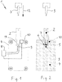
- FIG. 1 and 2 show a bending press 1 or press brake with two tool halves 2, 3 designed as a die (for example lower tool) and punch (for example upper tool) which can be moved relative to one another along a pressing direction 12.
- a platform 4 in particular in the form of a table, carries a tool half 2 (lower tool) which is displaceably mounted on the platform 4 by means of a bearing.
- the bearing is a gas bearing 5 which can be acted upon with a gaseous medium, in particular an air bearing Gas outlet openings 6 in the bearing surface 7 ( Fig. 2 ) to create a gas cushion.
- the tool half 2 can be moved floating on the gas cushion.
- the gas bearing 5 can be formed from a porous material, in particular from porous ceramic, or from foamed metal, in particular foamed titanium or foamed steel. Here the pores form the gas outlet openings on the bearing surface 7.
- a bearing surface 7 with bores can also be used as gas outlet openings 6.
- the bending press 1 or press brake comprises a gas supply device 8 for loading the gas bearing 5 with a gaseous medium.
- a gas supply device 8 for loading the gas bearing 5 with a gaseous medium.
- This preferably comprises a blower and a feed line which opens into a channel 6 running inside the platform 4, which runs below the gas bearing 5 and supplies it with a gaseous medium.
- the bending press 1 or press brake Fig. 1 also has a fixing device 10, in particular a clamping device in the form of a clamping strip, for fixing the tool half 2 slidably mounted on the platform 4 relative to the platform 4.
- a fixing device 10 in particular a clamping device in the form of a clamping strip, for fixing the tool half 2 slidably mounted on the platform 4 relative to the platform 4.
- the fixing device 10 is coupled to the gas supply device 8 in such a way that no gas is introduced into the gas bearing 5 when the fixing device 10 is closed.
- the fixing device 10 can have a sensor or limit switch which is connected to the gas supply device via a signal line (possibly with the interposition of a machine control).
- the coupling can take place in such a way that when the fixing device 10 is in the closed position, ie the tool half 2 is locked, the gas supply device 8 is switched off or a supply valve of the gas supply device 8 is closed.
- the tool half 2 slidably mounted on the platform 4 is designed as a lower tool and the other tool half 3 is designed as an upper tool.
- the gas bearing 5 is located between the lower tool and the platform 4.
- the tool half 2, which is displaceably mounted on the platform 4, could also be held by a tool holder (not shown). In this case, the gas bearing 5 could be formed between the tool holder and the platform 4.
- the bearing surface 7 with the gas outlet openings 6 is designed to be stationary with the platform 4. It would of course also be conceivable to design the bearing surface 7 having gas outlet openings 6 in a stationary manner with the tool half 2, for example in the foot region of the lower tool.
- the tool half 2 slidably mounted on the platform 4 is seated in a guide 11, the bottom of which is at least partially formed by the bearing surface 7 of the gas bearing 5.
- the gas bearing 5 is a linear bearing, with the direction of displacement of the tool half 2 mounted on the platform 4 in the linear bearing essentially perpendicular to the pressing direction 12 ( Fig. 1 ) of the machine tool 1.
- the tool halves 2, 3 are elongated and the direction of displacement of the tool half 2 slidably mounted on the platform 4 is parallel to its longitudinal extent.
- the in the Fig. 3 shown bending press 21 or press brake differs from the previously described bending press 1 according to the 1 and 2 only by designing the platform 24.
- two gas bearings 25 are provided on the platform 24 by way of example.
- the gas bearings 25 are on both sides of the guide 31 for the tool half 22 on the platform 24 arranged.
- the gas bearings 25 are advantageously designed as linear bearings and run essentially parallel to one another and parallel to the guide 31.
Landscapes
- Engineering & Computer Science (AREA)
- Mechanical Engineering (AREA)
- General Engineering & Computer Science (AREA)
- Bending Of Plates, Rods, And Pipes (AREA)
- Magnetic Bearings And Hydrostatic Bearings (AREA)
- Shaping Metal By Deep-Drawing, Or The Like (AREA)
Description
- Die Erfindung betrifft eine Biegepresse oder eine Abkantpresse mit zwei, als Matrize und Stempel ausgeführten Werkzeughälften, die relativ zueinander bewegbar sind, und mit einer Plattform, insbesondere einem Tisch, wobei eine Werkzeughälfte mittels eines Lagers an der Plattform verschiebbar gelagert ist. Solch eine Biegepresse ist zum Beispiel in der
US-A-5146774 offenbart. - Bei Biegepressen, insbesondere für das Biegen oder Abkanten von Blechstücken, ist es bekannt, Unterwerkzeuge auf dem Tisch der Werkzeugmaschine verschiebbar zu lagern, einerseits zum Justieren des Unterwerkzeuges und andererseits zum Austauschen des Unterwerkzeuges. Zurzeit werden zur Minimierung des Verschleisses von Unterwerkzeugen und Tischen spezielle Härteverfahren für die aneinander gleitenden Flächen angewandt und Gleitöle an der Kontaktfläche eingesetzt.
- Nachteil dieser Vorgehensweise ist der Verzug beim Härten der Tische bzw. Werkzeuge und der hohe Aufwand in der Fertigung. Zudem werden oft selbst in gehärteten Oberflächen der Tische Beschädigungen festgestellt, da der Zunder von dem zu bearbeitenden Blech eine höhere Härte aufweist. Diese Beschädigungen entstehen durch das Verschieben der Unterwerkzeuge, die zumeist als Matrizen ausgebildet sind, auf dem Tisch, vornehmlich wenn Schmutz oder Zunder zwischen Matrize und Tisch vorhanden ist.
- Die Erfindung stellt sich die Aufgabe, diese Nachteile zu beseitigen und eine Biegepresse oder eine Abkantpresse bereitzustellen, bei der keine Beschädigungen durch das Verschieben eines Werkzeuges bzw. Werkzeughälfte an der Plattform entstehen. Verunreinigungen und Zunder sollen dabei von der Lagerfläche möglichst ferngehalten werden. Das Verschieben der Werkzeughälfte soll gleichzeitig möglichst reibungsfrei erfolgen. Die Lösung soll zuverlässig, langlebig, kostengünstig und gegebenenfalls auf bestehende Biegepressen oder Abkantpressen nachrüstbar sein.
- Diese Aufgabe wird mit einer eingangs erwähnten Biegepresse, Gesenkbiegepresse, Abkantpresse oder dergleichen dadurch gelöst, dass das Lager ein mit einem gasförmigen Medium beaufschlagbares Gaslager, insbesondere ein Luftlager, mit Gasaustrittsöffnungen in der Lagerfläche zur Erzeugung eines Gaspolsters ist.
- Dadurch kann die Werkzeughälfte schwebend und damit in hohem Mass reibungsfrei auf dem entstehenden Gas- bzw. Luftpolster verschoben werden. Ein zusätzlicher positiver Effekt entsteht durch den Gasstrom aus den Gasaustrittsöffnungen, da diesen den Schmutz und/oder den Zunder wegbläst. So wird die Lagerfläche stets von Verunreinigungen sauber gehalten. Der Verschleiss zwischen den gegeneinander bewegbaren Teilen wird dadurch auf ein Minimum begrenzt.
- Als Gaslager wird ein Luftlager bevorzugt, allerdings wäre es durchaus möglich, anstelle von Luft auch andere Gase oder Gasgemische zu verwenden, die z.B. in einem Gasreservoir zur Verfügung stehen.
- Die verschiebbare Lagerung der Werkzeughälfte auf der Plattform dient insbesondere der Justierung und dem Austausch der Werkzeughälfte. Die Werkzeughälfte ist dabei in einer Führung der Plattform geführt. Bei grossen Biegepressen können Unter- und Oberwergzeug beachtliche Längen aufweisen. Die verschiebbare Lagerung an der Plattform bezieht sich dabei vorzugsweise auf eine lineare Bewegung parallel zur Längserstreckung der entsprechenden Werkzeughälfte.
- Die Plattform der Biegepresse oder Abkantpresse kann z.B. ein Tisch, ein Sockel, ein Gerüst, ein Gestell, ein Pressbalken und dergleichen sein.
- Bevorzugt sind zumindest zwei Gaslager zur Erzeugung eines Gaspolsters zwischen einer Werkzeughälfte und der Plattform vorgesehen, wodurch die entsprechende Werkzeughälfte besonders einfach an der Plattform verschiebbar ist. Besonders bei grossen und somit zumeist schweren Werkzeughälften ist die Anordnung von zwei oder mehreren auf die Werkzeughälfte wirkenden Gaslagern vorteilhaft. Des Weiteren an einer gattungsgemässen Biegepresse oder Abkantpresse mehrere, teilweise unterschiedlich ausgebildete Werkzeughälften hintereinander angeordnet sein, so dass verschiedene Biegevorgänge nacheinander ausführbar sind. Bei der Anordnung von zumindest zwei Gaslagern sind auch bei etwaigen Abmessungsunterschieden insbesondere im Bereich der entsprechenden Lagerflächen der Gaslager diese Werkzeughälften weiterhin einfach an der Plattform verschiebbar.
- Bevorzugt ist das Gaslager aus einem porösen Material, insbesondere aus poröser Keramik, gebildet. Dies erlaubt eine kostengünstige Lösung und gewährleistet einen gleichmässigen Gasstrom bzw. Luftpolster.
- Bevorzugt ist das Gaslager aus geschäumtem Metall, insbesondere geschäumtem Titan oder geschäumtem Stahl, gebildet, wodurch eine hohe Festigkeit und daher lange Lebensdauer erzielt werden kann.
- Bevorzugt umfasst die Biegepresse oder Abkantpresse eine Gasversorgungseinrichtung zur Beaufschlagung des Gaslagers mit einem gasförmigen Medium. Die Gasversorgungseinrichtung ist hier in der Biegepresse oder Abkantpresse mitintegriert, so dass kein externer Anschluss nötig ist. Unter dem Begriff Gasversorgungseinrichtung werden auch Komponenten wie Zuführleitungen verstanden. Eine Gasversorgungseinrichtung kann z.B. aus einer Ansaugleitung bzw. -Öffnung, einem Gebläse bzw. Pumpe, Ventil(en) und einer Zuführleitung bestehen.
- Bevorzugt umfasst die Biegepresse oder Abkantpresse eine Fixiereinrichtung, insbesondere Klemmeinrichtung, zur Fixierung der an der Plattform verschiebbar gelagerten Werkzeughälfte relativ zur Plattform. Dies erlaubt eine zuverlässige und fixe Einstellung der Biegepresse oder Abkantpresse. Die Klemmeinrichtung kann z.B. in Form einer Klemmleiste ausgebildet sein, die in arretierter Stellung vorteilhaft seitlich gegen die Werkzeughälfte drückt und diese somit gegen die gegenüberliegende Wand der Führung drückt.
- Bevorzugt ist die Fixiereinrichtung mit der Gasversorgungseinrichtung derart gekoppelt, dass bei geschlossener Fixiereinrichtung kein Gas in das Gaslager eingebracht wird. Dadurch kann der Gas- bzw. Energieverbrauch minimiert werden. Die Fixiereinrichtung kann hierfür einen Sensor oder Endschalter aufweisen, der über eine Signalleitung mit der Gasversorgungseinrichtung (gegebenenfalls unter Zwischenschaltung der Maschinensteuerung) verbunden ist. Die Kopplung kann derart erfolgen, dass bei geschlossener, d.h. die Werkzeughälfte arretierender Stellung der Fixiereinrichtung die Gasversorgungseinrichtung abgeschaltet oder ein Zuführventil der Gasversorgungseinrichtung geschlossen wird. Alternativ wäre auch eine mechanische Kopplung möglich.
- Bevorzugt ist die an der Plattform verschiebbar gelagerte Werkzeughälfte als Unterwerkzeug ausgebildet und die andere Werkzeughälfte als Oberwerkzeug ausgebildet, wobei das Gaslager zwischen dem Unterwerkzeug und der Plattform ausgebildet ist.
- Bevorzugt ist die Gasaustrittsöffnungen aufweisende Lagerfläche ortsfest mit der Plattform ausgebildet. Hier muss die Zuführleitung der Gasversorgungseinrichtung beim Verschieben der Werkzeughälfte nicht mitbewegt werden.
- Bevorzugt ist die Gasaustrittsöffnungen aufweisende Lagerfläche ortsfest mit der an der Plattform verschiebbar gelagerten Werkzeughälfte ausgebildet, wobei vorzugsweise die Lagerfläche im Fussbereich einer als Unterwerkzeug ausgebildeten Werkzeughälfte ausgebildet ist. Durch diese Massnahme kann der Gas- bzw. Luftverbrauch minimiert werden, insbesondere da die Führung in der Plattform länger ist als die darin verschiebbare Werkzeughälfte. Die Zuführleitung für das Gas könnte in dieser Ausführungsform nach dem Einbau der Werkzeughälfte in die Plattform an eine dafür vorgesehene Kupplung des Gaslagers angeschlossen werden.
- Bevorzugt sitzt die an der Plattform verschiebbar gelagerte Werkzeughälfte in einer Führung, deren Boden zumindest teilweise durch die Lagerfläche des Gaslagers gebildet wird. Dies ermöglicht eine exakte und reibungsfreie Einstellung, insb. der entsprechenden Werkzeughälfte.
- Bevorzugt verläuft unterhalb des Gaslagers ein Kanal zur Versorgung des Gaslagers mit einem gasförmigen Medium. Der Kanal (Hohlraum zur Gasversorgung) bildet einen Überdruckbereich, aus dem das Gas durch die Gasaustrittsöffnungen nach oben strömt.
- Bevorzugt wird die an der Plattform verschiebbar gelagerte Werkzeughälfte von einer Werkzeughalterung gehalten und ist das Gaslager zwischen Werkzeughalterung und Plattform ausgebildet.
- Bevorzugt ist das Gaslager ein Linearlager, wobei die Verschieberichtung der an der Plattform gelagerten Werkzeughälfte im Linearlager im Wesentlichen senkrecht zur Pressrichtung der Werkzeugmaschine steht.
- Bevorzugt sind die Werkzeughälften länglich und steht die Verschieberichtung der an der Plattform verschiebbar gelagerten Werkzeughälfte parallel zu ihrer Längserstreckung, was eine konstruktiv einfache Ausgestaltung der Biegepresse oder Abkantpresse ermöglicht.
- In einer bevorzugten Ausführungsform wird vorgeschlagen, die Matrize (Unterwerkzeug) oder den Tisch der Biegepresse oder Abkantpresse mit einem Luftlager auszustatten. Dazu wird beispielsweise im Tisch eine poröse Keramik oder geschäumtes Metall eingearbeitet und mit Luft beaufschlagt, so dass die Matrize auf dem entstehenden Luftpolster "schwebend" verschoben werden kann. Ein zusätzlicher Effekt entsteht durch den Luftstrom, der Schmutz oder Zunder wegbläst.
- Denkbar ist auch die Matrize an ihrem Fuss mit einem Luftlager (Lagerfläche mit Öffnungen) auszustatten und somit den Luftverbrauch zu minimieren. Zusätzlich wird vorgeschlagen, den Luftstrom nur beim Öffnen der Fixiereinrichtung (Öffnen der Klemmung) anzulegen, sodass der Luftverbrauch minimiert wird. Auch kann an Stelle einer porösen Keramik ein herkömmliches Luftlager (Mikrobohrungen in Druckkammer) verwendet werden.
- Vorteilhafte Weiterbildungen sind in den Figuren und in den abhängigen Patentansprüchen dargelegt.
- Weitere Vorteile, Merkmale und Einzelheiten der Erfindung ergeben sich aus der nachfolgenden Beschreibung, in der unter Bezugnahme auf die Zeichnungen Ausführungsbeispiele der Erfindung beschrieben sind. Dabei können die in den Ansprüchen und in der Beschreibung erwähnten Merkmale jeweils einzeln für sich oder in beliebiger Kombination erfindungswesentlich sein.
- Die Bezugszeichenliste ist Bestandteil der Offenbarung. Die Figuren werden zusammenhängend und übergreifend beschrieben. Gleiche Bezugszeichen bedeuten gleiche Bauteile.
- Es zeigen dabei:
- Fig. 1
- eine erfindungsgemässe Biegepresse oder Abkantpresse in Seitenansicht,
- Fig. 2
- eine erfindungsgemässe Biegepresse oder Abkantpresse im Schnitt, und
- Fig. 3
- eine Variante einer Biegepresse oder Abkantpresse im Schnitt.
-
Fig. 1 und 2 zeigen eine Biegepresse 1 oder Abkantpresse mit zwei, als Matrize (bspw. Unterwerkzeug) und Stempel (bspw. Oberwerkzeug) ausgeführten Werkzeughälften 2, 3, die entlang einer Pressrichtung 12 relativ zueinander bewegbar sind. - Eine Plattform 4, insbesondere in Form eines Tisches, trägt eine Werkzeughälfte 2 (Unterwerkzeug), die mittels eines Lagers an der Plattform 4 verschiebbar gelagert ist. Das Lager ist ein mit einem gasförmigen Medium beaufschlagbares Gaslager 5, insbesondere ein Luftlager, mit Gasaustrittsöffnungen 6 in der Lagerfläche 7 (
Fig. 2 ) zur Erzeugung eines Gaspolsters. Auf dem Gaspolster kann die Werkzeughälfte 2 schwebend verschoben werden. - Das Gaslager 5 kann aus einem porösen Material, insbesondere aus poröser Keramik, oder aus geschäumtem Metall, insbesondere geschäumtem Titan oder geschäumtem Stahl, gebildet sein. Hier bilden die Poren die Gasaustrittsöffnungen an der Lagerfläche 7.
- In einer nicht erfindungsgemässen Alternative kann auch eine Lagerfläche 7 mit Bohrungen als Gasaustrittsöffnungen 6 verwendet werden.
- In
Fig. 1 ist zu sehen, dass die Biegepresse 1 oder Abkantpresse eine Gasversorgungseinrichtung 8 zur Beaufschlagung des Gaslagers 5 mit einem gasförmigen Medium umfasst. Diese umfasst vorzugsweise ein Gebläse und eine Zuführleitung, die in einen im Inneren der Plattform 4 verlaufenden Kanal 6 mündet, der unterhalb des Gaslagers 5 verläuft und dieses mit einem gasförmigen Medium versorgt. - Die Biegepresse 1 oder Abkantpresse aus
Fig. 1 weist auch eine Fixiereinrichtung 10, insbesondere eine Klemmeinrichtung in Form einer Klemmleiste, auf zur Fixierung der an der Plattform 4 verschiebbar gelagerten Werkzeughälfte 2 relativ zur Plattform 4. - In der dargestellten bevorzugten Ausführungsform ist die Fixiereinrichtung 10 mit der Gasversorgungseinrichtung 8 derart gekoppelt, dass bei geschlossener Fixiereinrichtung 10 kein Gas in das Gaslager 5 eingebracht wird. Die Fixiereinrichtung 10 kann hierfür einen Sensor oder Endschalter aufweisen, der über eine Signalleitung mit der Gasversorgungseinrichtung (gegebenenfalls unter Zwischenschaltung einer Maschinensteuerung) verbunden ist. Die Kopplung kann derart erfolgen, dass bei geschlossener, d.h. die Werkzeughälfte 2 arretierender Stellung der Fixiereinrichtung 10, die Gasversorgungseinrichtung 8 abgeschaltet oder ein Zuführventil der Gasversorgungseinrichtung 8 geschlossen wird. Alternativ wäre auch eine mechanische Kopplung möglich. Jedenfalls strömt bei arretierter Werkzeughälfte 2 vorteilhaft kein Gas aus der Lagerfläche 7.
- Die an der Plattform 4 verschiebbar gelagerte Werkzeughälfte 2 ist als Unterwerkzeug ausgebildet und die andere Werkzeughälfte 3 als Oberwerkzeug ausgebildet. Das Gaslager 5 befindet sich zwischen dem Unterwerkzeug und der Plattform 4. Die an der Plattform 4 verschiebbar gelagerte Werkzeughälfte 2 könnte auch von einer Werkzeughalterung (nicht dargestellt) gehalten werden. In diesem Fall könnte das Gaslager 5 zwischen Werkzeughalterung und Plattform 4 ausgebildet sein.
- In der in
Fig. 1 und 2 dargestellten Ausführungsform ist die Lagerfläche 7 mit den Gasaustrittsöffnungen 6 ortsfest mit der Plattform 4 ausgebildet. Denkbar wäre selbstverständlich auch, die Gasaustrittsöffnungen 6 aufweisende Lagerfläche 7 ortsfest mit der Werkzeughälfte 2 auszubilden, z.B. im Fussbereich des Unterwerkzeuges. - Die an der Plattform 4 verschiebbar gelagerte Werkzeughälfte 2 sitzt in einer Führung 11, deren Boden zumindest teilweise durch die Lagerfläche 7 des Gaslagers 5 gebildet wird.
- Das Gaslager 5 ist vorliegend ein Linearlager, wobei die Verschieberichtung der an der Plattform 4 gelagerten Werkzeughälfte 2 im Linearlager im Wesentlichen senkrecht zur Pressrichtung 12 (
Fig. 1 ) der Werkzeugmaschine 1 steht. Die Werkzeughälften 2, 3 sind länglich und die Verschieberichtung der an der Plattform 4 verschiebbar gelagerten Werkzeughälfte 2 steht parallel zu ihrer Längserstreckung. - Die in der
Fig. 3 gezeigte Biegepresse 21 oder Abkantpresse unterscheidet sich von der zuvor beschriebenen Biegepresse 1 gemäss denFig. 1 und 2 lediglich durch die Ausgestaltung der Plattform 24. Zur Erzeugung eines Gaspolsters zwischen der Werkzeughälfte 22 und der Plattform 24 sind beispielhaft zwei Gaslager 25 an der Plattform 24 vorgesehen. Die Gaslager 25 sind beidseitig der Führung 31 für die Werkzeughälfte 22 an der Plattform 24 angeordnet. Vorteilhaft sind die Gaslager 25 als Linearlager ausgebildet und verlaufen im Wesentlichen parallel zueinander sowie parallel zu der Führung 31. - Im Übrigen gelten die vorgenannten Ausführungen zu der zuvor beschriebenen Biegepresse 1 gemäss den
Fig. 1 und 2 auch für die Biegepresse 21 beziehungsweise sind auf die übertragbar. Dies gilt insbesondere für die Ausführungen zur Gasversorgungseinrichtung 8. - Die Erfindung ist nicht auf die dargestellten Ausführungsformen und deren Merkmale beschränkt, sondern kann vielfach abgewandelt und erweitert werden. Insbesondere ist es möglich, durch Kombination der beschriebenen und dargestellten Merkmale weitere Ausführungsvarianten zu verwirklichen, ohne den Rahmen der Erfindung zu verlassen.
Bezugszeichenliste 1 Biegepresse 21 Biegepresse 2 Werkzeughälfte 22 Werkzeughälfte 3 Werkzeughälfte 23 Werkzeughälfte 4 Plattform 24 Plattform 5 Gaslager 25 Gaslager 6 Gasaustrittsöffnungen 26 Gasaustrittsöffnungen 7 Lagerfläche 27 Lagerfläche 8 Gasversorgungseinrichtung 9 Kanal 10 Fixiereinrichtung 30 Fixiereinrichtung 11 Führung 31 Führung 12 Pressrichtung
Claims (15)
- Biegepresse (1; 21) oder Abkantpresse mit zwei, als Matrize und Stempel ausgeführten Werkzeughälften (2, 3; 22, 23), die relativ zueinander bewegbar sind, und mit einer Plattform (4; 24), insbesondere einem Tisch, wobei eine Werkzeughälfte (2; 22) mittels eines Lagers an der Plattform (4; 24) verschiebbar gelagert ist, dadurch gekennzeichnet, dass das Lager ein mit einem gasförmigen Medium beaufschlagbares Gaslager (5; 25), insbesondere ein Luftlager, mit Gasaustrittsöffnungen (6; 26) in der Lagerfläche (7; 27) zur Erzeugung eines Gaspolsters ist.
- Biegepresse oder Abkantpresse nach Anspruch 1, dadurch gekennzeichnet, dass zumindest zwei Gaslager (25) zur Erzeugung eines Gaspolsters zwischen der Werkzeughälfte (22) und der Plattform (24) vorgesehen sind.
- Biegepresse oder Abkantpresse nach Anspruch 1 oder 2, dadurch gekennzeichnet, dass das Gaslager (5; 25) aus einem porösen Material, insbesondere aus poröser Keramik, gebildet ist.
- Biegepresse oder Abkantpresse nach Anspruch 1 oder 2, dadurch gekennzeichnet, dass das Gaslager (5; 25) aus geschäumtem Metall, insbesondere geschäumtem Titan oder geschäumtem Stahl, gebildet ist.
- Biegepresse oder Abkantpresse nach einem der vorhergehenden Ansprüche, dadurch gekennzeichnet, dass die Biegepresse (1; 21) oder Abkantpresse eine Gasversorgungseinrichtung (8) zur Beaufschlagung des Gaslagers (5) mit einem gasförmigen Medium umfasst.
- Biegepresse oder Abkantpresse nach einem der vorhergehenden Ansprüche, dadurch gekennzeichnet, dass die Biegepresse (1; 21) oder Abkantpresse eine Fixiereinrichtung (10; 30), insbesondere Klemmeinrichtung, zur Fixierung der an der Plattform (4; 24) verschiebbar gelagerten Werkzeughälfte (2; 22) relativ zur Plattform (4; 24) umfasst.
- Biegepresse oder Abkantpresse nach Anspruch 6, dadurch gekennzeichnet, dass die Fixiereinrichtung (10; 30) mit der Gasversorgungseinrichtung (8) derart gekoppelt ist, dass bei geschlossener Fixiereinrichtung (10; 30) kein Gas in das Gaslager (5; 25) eingebracht wird.
- Biegepresse oder Abkantpresse nach einem der vorhergehenden Ansprüche, dadurch gekennzeichnet, dass die an der Plattform (4; 24) verschiebbar gelagerte Werkzeughälfte (2; 22) als Unterwerkzeug ausgebildet ist und die andere Werkzeughälfte (3; 23) als Oberwerkzeug ausgebildet ist, wobei das Gaslager (5; 25) zwischen dem Unterwerkzeug (2; 22) und der Plattform (4; 24) ausgebildet ist.
- Biegepresse oder Abkantpresse nach einem der vorhergehenden Ansprüche, dadurch gekennzeichnet, dass die Gasaustrittsöffnungen (6; 26) aufweisende Lagerfläche (7; 27) ortsfest mit der Plattform (4; 24) ausgebildet ist.
- Biegepresse oder Abkantpresse nach einem der vorhergehenden Ansprüche, dadurch gekennzeichnet, dass die Gasaustrittsöffnungen (6) aufweisende Lagerfläche (7) ortsfest mit der an der Plattform (4) verschiebbar gelagerten Werkzeughälfte (2) ausgebildet ist, wobei vorzugsweise die Lagerfläche (7) im Fussbereich einer als Unterwerkzeug ausgebildeten Werkzeughälfte (2) ausgebildet ist.
- Biegepresse oder Abkantpresse nach einem der vorhergehenden Ansprüche, dadurch gekennzeichnet, dass die an der Plattform (4) verschiebbar gelagerte Werkzeughälfte (2) in einer Führung (11) sitzt, deren Boden zumindest teilweise durch die Lagerfläche (7) des Gaslagers (5) gebildet wird.
- Biegepresse oder Abkantpresse nach einem der vorhergehenden Ansprüche, dadurch gekennzeichnet, dass unterhalb des Gaslagers (5) ein Kanal (9) zur Versorgung des Gaslagers (5) mit einem gasförmigen Medium verläuft.
- Biegepresse oder Abkantpresse nach einem der vorhergehenden Ansprüche, dadurch gekennzeichnet, dass die an der Plattform (4) verschiebbar gelagerte Werkzeughälfte (2) von einer Werkzeughalterung gehalten wird und das Gaslager (5) zwischen Werkzeughalterung und Plattform (4) ausgebildet ist.
- Biegepresse oder Abkantpresse nach einem der vorhergehenden Ansprüche, dadurch gekennzeichnet, dass das Gaslager (5; 25) ein Linearlager ist, wobei die Verschieberichtung der an der Plattform (4; 24) gelagerten Werkzeughälfte (2; 22) im Linearlager im Wesentlichen senkrecht zur Pressrichtung (12) der Werkzeugmaschine (1; 21) steht.
- Biegepresse oder Abkantpresse nach einem der vorhergehenden Ansprüche, dadurch gekennzeichnet, dass die Werkzeughälften (2, 3; 22, 23) länglich sind und die Verschieberichtung der an der Plattform (4; 24) verschiebbar gelagerten Werkzeughälfte (2; 22) parallel zu ihrer Längserstreckung steht.
Applications Claiming Priority (2)
| Application Number | Priority Date | Filing Date | Title |
|---|---|---|---|
| DE202013005962U DE202013005962U1 (de) | 2013-07-03 | 2013-07-03 | Werkzeugmaschine |
| PCT/IB2014/062652 WO2015001454A1 (de) | 2013-07-03 | 2014-06-27 | Werkzeugmaschine |
Publications (2)
| Publication Number | Publication Date |
|---|---|
| EP3016756A1 EP3016756A1 (de) | 2016-05-11 |
| EP3016756B1 true EP3016756B1 (de) | 2020-03-04 |
Family
ID=49044347
Family Applications (1)
| Application Number | Title | Priority Date | Filing Date |
|---|---|---|---|
| EP14747717.8A Active EP3016756B1 (de) | 2013-07-03 | 2014-06-27 | Biegepresse oder abkantpresse |
Country Status (3)
| Country | Link |
|---|---|
| EP (1) | EP3016756B1 (de) |
| DE (1) | DE202013005962U1 (de) |
| WO (1) | WO2015001454A1 (de) |
Families Citing this family (2)
| Publication number | Priority date | Publication date | Assignee | Title |
|---|---|---|---|---|
| AT520541B1 (de) * | 2018-05-07 | 2019-05-15 | Trumpf Maschinen Austria Gmbh & Co Kg | Unterwerkzeug mit Reibreduktionsvorrichtung |
| CN117399470B (zh) * | 2023-11-09 | 2026-04-24 | 王勇 | 一种挠度自适应补偿装置及包含其的折弯机 |
Family Cites Families (3)
| Publication number | Priority date | Publication date | Assignee | Title |
|---|---|---|---|---|
| JPS57199523A (en) * | 1982-05-28 | 1982-12-07 | Hitachi Ltd | Bending die holding device |
| US5146774A (en) * | 1991-02-27 | 1992-09-15 | Uniflo Conveyor, Inc. | Lift mechanism for installation and removal of press brake dies |
| US5354168A (en) * | 1992-11-03 | 1994-10-11 | The United States Of America As Represented By The United States Department Of Energy | Apparatus for restraining and transporting dies |
-
2013
- 2013-07-03 DE DE202013005962U patent/DE202013005962U1/de not_active Expired - Lifetime
-
2014
- 2014-06-27 EP EP14747717.8A patent/EP3016756B1/de active Active
- 2014-06-27 WO PCT/IB2014/062652 patent/WO2015001454A1/de not_active Ceased
Non-Patent Citations (1)
| Title |
|---|
| None * |
Also Published As
| Publication number | Publication date |
|---|---|
| EP3016756A1 (de) | 2016-05-11 |
| DE202013005962U1 (de) | 2013-07-31 |
| WO2015001454A4 (de) | 2015-03-05 |
| WO2015001454A1 (de) | 2015-01-08 |
Similar Documents
| Publication | Publication Date | Title |
|---|---|---|
| EP2990192B2 (de) | Pressumformwerkzeug mit toleranzausgleich | |
| DE102015006019B3 (de) | Unterbauspanner mit in sich gefedertem Gelenkparallelogramm | |
| EP1910029B1 (de) | Spannvorrichtung | |
| DE102015220231B4 (de) | Vorrichtung zum Tiefziehen eines Blechzuschnittes mit Formwerkzeugen | |
| EP2722194A1 (de) | Werkzeug zum Bearbeiten von Werkstücken, insbesondere Blechen | |
| DE20318208U1 (de) | Spannwerkzeug, insbesondere Kniehebelspannvorrichtung | |
| DE102015103112B4 (de) | Werkzeugschieber | |
| EP2165797A1 (de) | Bearbeitungsvorrichtung für gelötete Werkstücke | |
| EP3016756A1 (de) | Werkzeugmaschine | |
| DE102006025034A1 (de) | Vorrichtung und Verfahren zur Herstellung von Profilkörpern | |
| DE102014112320B4 (de) | Pressumformwerkzeug mit Ausgleichskissen | |
| DE102014115766B4 (de) | Scheibenbremse für ein Nutzfahrzeug | |
| DE202009002076U1 (de) | Linearachse | |
| DE102009008137A1 (de) | Verfahren und Vorrichtung zum Innendruck-Umformen eines Hohlkörpers aus Metall | |
| DE102014102993A1 (de) | Werkzeugschieber | |
| DE19858837B4 (de) | Presse zum Innenhochdruckumformen | |
| DE602005005010T2 (de) | Vorrichtung zum Bruchtrennen des Kopflagers einer Pleuelstange | |
| EP1799372B1 (de) | Verfahren und vorrichtung zum herstellen und/oder bearbeiten von teilen | |
| DE102018109313B3 (de) | Maschinenspindelanordnung | |
| AT528004B1 (de) | Maschinenelement zum Aufspannen einer Form | |
| DE102010034929A1 (de) | Verfahren und Einstellwerkzeug zur Einstellung der Vorspannung von Wälzkörperführungen | |
| EP3646982B1 (de) | Schweisselektrode | |
| EP2221125B1 (de) | Hydroformwerkzeug | |
| DE102010031990A1 (de) | Umformwerkzeug | |
| EP3412411B1 (de) | Spannsystem |
Legal Events
| Date | Code | Title | Description |
|---|---|---|---|
| PUAI | Public reference made under article 153(3) epc to a published international application that has entered the european phase |
Free format text: ORIGINAL CODE: 0009012 |
|
| 17P | Request for examination filed |
Effective date: 20160203 |
|
| AK | Designated contracting states |
Kind code of ref document: A1 Designated state(s): AL AT BE BG CH CY CZ DE DK EE ES FI FR GB GR HR HU IE IS IT LI LT LU LV MC MK MT NL NO PL PT RO RS SE SI SK SM TR |
|
| AX | Request for extension of the european patent |
Extension state: BA ME |
|
| DAX | Request for extension of the european patent (deleted) | ||
| STAA | Information on the status of an ep patent application or granted ep patent |
Free format text: STATUS: EXAMINATION IS IN PROGRESS |
|
| 17Q | First examination report despatched |
Effective date: 20190402 |
|
| GRAP | Despatch of communication of intention to grant a patent |
Free format text: ORIGINAL CODE: EPIDOSNIGR1 |
|
| STAA | Information on the status of an ep patent application or granted ep patent |
Free format text: STATUS: GRANT OF PATENT IS INTENDED |
|
| INTG | Intention to grant announced |
Effective date: 20190927 |
|
| GRAS | Grant fee paid |
Free format text: ORIGINAL CODE: EPIDOSNIGR3 |
|
| GRAA | (expected) grant |
Free format text: ORIGINAL CODE: 0009210 |
|
| STAA | Information on the status of an ep patent application or granted ep patent |
Free format text: STATUS: THE PATENT HAS BEEN GRANTED |
|
| AK | Designated contracting states |
Kind code of ref document: B1 Designated state(s): AL AT BE BG CH CY CZ DE DK EE ES FI FR GB GR HR HU IE IS IT LI LT LU LV MC MK MT NL NO PL PT RO RS SE SI SK SM TR |
|
| REG | Reference to a national code |
Ref country code: GB Ref legal event code: FG4D Free format text: NOT ENGLISH |
|
| REG | Reference to a national code |
Ref country code: CH Ref legal event code: EP |
|
| REG | Reference to a national code |
Ref country code: AT Ref legal event code: REF Ref document number: 1239799 Country of ref document: AT Kind code of ref document: T Effective date: 20200315 |
|
| REG | Reference to a national code |
Ref country code: DE Ref legal event code: R096 Ref document number: 502014013756 Country of ref document: DE |
|
| REG | Reference to a national code |
Ref country code: IE Ref legal event code: FG4D Free format text: LANGUAGE OF EP DOCUMENT: GERMAN |
|
| PG25 | Lapsed in a contracting state [announced via postgrant information from national office to epo] |
Ref country code: FI Free format text: LAPSE BECAUSE OF FAILURE TO SUBMIT A TRANSLATION OF THE DESCRIPTION OR TO PAY THE FEE WITHIN THE PRESCRIBED TIME-LIMIT Effective date: 20200304 Ref country code: NO Free format text: LAPSE BECAUSE OF FAILURE TO SUBMIT A TRANSLATION OF THE DESCRIPTION OR TO PAY THE FEE WITHIN THE PRESCRIBED TIME-LIMIT Effective date: 20200604 Ref country code: RS Free format text: LAPSE BECAUSE OF FAILURE TO SUBMIT A TRANSLATION OF THE DESCRIPTION OR TO PAY THE FEE WITHIN THE PRESCRIBED TIME-LIMIT Effective date: 20200304 |
|
| REG | Reference to a national code |
Ref country code: NL Ref legal event code: MP Effective date: 20200304 |
|
| PG25 | Lapsed in a contracting state [announced via postgrant information from national office to epo] |
Ref country code: GR Free format text: LAPSE BECAUSE OF FAILURE TO SUBMIT A TRANSLATION OF THE DESCRIPTION OR TO PAY THE FEE WITHIN THE PRESCRIBED TIME-LIMIT Effective date: 20200605 Ref country code: SE Free format text: LAPSE BECAUSE OF FAILURE TO SUBMIT A TRANSLATION OF THE DESCRIPTION OR TO PAY THE FEE WITHIN THE PRESCRIBED TIME-LIMIT Effective date: 20200304 Ref country code: BG Free format text: LAPSE BECAUSE OF FAILURE TO SUBMIT A TRANSLATION OF THE DESCRIPTION OR TO PAY THE FEE WITHIN THE PRESCRIBED TIME-LIMIT Effective date: 20200604 Ref country code: LV Free format text: LAPSE BECAUSE OF FAILURE TO SUBMIT A TRANSLATION OF THE DESCRIPTION OR TO PAY THE FEE WITHIN THE PRESCRIBED TIME-LIMIT Effective date: 20200304 Ref country code: HR Free format text: LAPSE BECAUSE OF FAILURE TO SUBMIT A TRANSLATION OF THE DESCRIPTION OR TO PAY THE FEE WITHIN THE PRESCRIBED TIME-LIMIT Effective date: 20200304 |
|
| REG | Reference to a national code |
Ref country code: LT Ref legal event code: MG4D |
|
| PG25 | Lapsed in a contracting state [announced via postgrant information from national office to epo] |
Ref country code: NL Free format text: LAPSE BECAUSE OF FAILURE TO SUBMIT A TRANSLATION OF THE DESCRIPTION OR TO PAY THE FEE WITHIN THE PRESCRIBED TIME-LIMIT Effective date: 20200304 |
|
| PG25 | Lapsed in a contracting state [announced via postgrant information from national office to epo] |
Ref country code: PT Free format text: LAPSE BECAUSE OF FAILURE TO SUBMIT A TRANSLATION OF THE DESCRIPTION OR TO PAY THE FEE WITHIN THE PRESCRIBED TIME-LIMIT Effective date: 20200729 Ref country code: ES Free format text: LAPSE BECAUSE OF FAILURE TO SUBMIT A TRANSLATION OF THE DESCRIPTION OR TO PAY THE FEE WITHIN THE PRESCRIBED TIME-LIMIT Effective date: 20200304 Ref country code: SK Free format text: LAPSE BECAUSE OF FAILURE TO SUBMIT A TRANSLATION OF THE DESCRIPTION OR TO PAY THE FEE WITHIN THE PRESCRIBED TIME-LIMIT Effective date: 20200304 Ref country code: IS Free format text: LAPSE BECAUSE OF FAILURE TO SUBMIT A TRANSLATION OF THE DESCRIPTION OR TO PAY THE FEE WITHIN THE PRESCRIBED TIME-LIMIT Effective date: 20200704 Ref country code: SM Free format text: LAPSE BECAUSE OF FAILURE TO SUBMIT A TRANSLATION OF THE DESCRIPTION OR TO PAY THE FEE WITHIN THE PRESCRIBED TIME-LIMIT Effective date: 20200304 Ref country code: EE Free format text: LAPSE BECAUSE OF FAILURE TO SUBMIT A TRANSLATION OF THE DESCRIPTION OR TO PAY THE FEE WITHIN THE PRESCRIBED TIME-LIMIT Effective date: 20200304 Ref country code: LT Free format text: LAPSE BECAUSE OF FAILURE TO SUBMIT A TRANSLATION OF THE DESCRIPTION OR TO PAY THE FEE WITHIN THE PRESCRIBED TIME-LIMIT Effective date: 20200304 Ref country code: RO Free format text: LAPSE BECAUSE OF FAILURE TO SUBMIT A TRANSLATION OF THE DESCRIPTION OR TO PAY THE FEE WITHIN THE PRESCRIBED TIME-LIMIT Effective date: 20200304 Ref country code: CZ Free format text: LAPSE BECAUSE OF FAILURE TO SUBMIT A TRANSLATION OF THE DESCRIPTION OR TO PAY THE FEE WITHIN THE PRESCRIBED TIME-LIMIT Effective date: 20200304 |
|
| REG | Reference to a national code |
Ref country code: DE Ref legal event code: R097 Ref document number: 502014013756 Country of ref document: DE |
|
| PLBE | No opposition filed within time limit |
Free format text: ORIGINAL CODE: 0009261 |
|
| STAA | Information on the status of an ep patent application or granted ep patent |
Free format text: STATUS: NO OPPOSITION FILED WITHIN TIME LIMIT |
|
| PG25 | Lapsed in a contracting state [announced via postgrant information from national office to epo] |
Ref country code: DK Free format text: LAPSE BECAUSE OF FAILURE TO SUBMIT A TRANSLATION OF THE DESCRIPTION OR TO PAY THE FEE WITHIN THE PRESCRIBED TIME-LIMIT Effective date: 20200304 Ref country code: MC Free format text: LAPSE BECAUSE OF FAILURE TO SUBMIT A TRANSLATION OF THE DESCRIPTION OR TO PAY THE FEE WITHIN THE PRESCRIBED TIME-LIMIT Effective date: 20200304 |
|
| REG | Reference to a national code |
Ref country code: CH Ref legal event code: PL |
|
| 26N | No opposition filed |
Effective date: 20201207 |
|
| PG25 | Lapsed in a contracting state [announced via postgrant information from national office to epo] |
Ref country code: PL Free format text: LAPSE BECAUSE OF FAILURE TO SUBMIT A TRANSLATION OF THE DESCRIPTION OR TO PAY THE FEE WITHIN THE PRESCRIBED TIME-LIMIT Effective date: 20200304 Ref country code: SI Free format text: LAPSE BECAUSE OF FAILURE TO SUBMIT A TRANSLATION OF THE DESCRIPTION OR TO PAY THE FEE WITHIN THE PRESCRIBED TIME-LIMIT Effective date: 20200304 |
|
| GBPC | Gb: european patent ceased through non-payment of renewal fee |
Effective date: 20200627 |
|
| PG25 | Lapsed in a contracting state [announced via postgrant information from national office to epo] |
Ref country code: LU Free format text: LAPSE BECAUSE OF NON-PAYMENT OF DUE FEES Effective date: 20200627 |
|
| PG25 | Lapsed in a contracting state [announced via postgrant information from national office to epo] |
Ref country code: IE Free format text: LAPSE BECAUSE OF NON-PAYMENT OF DUE FEES Effective date: 20200627 Ref country code: LI Free format text: LAPSE BECAUSE OF NON-PAYMENT OF DUE FEES Effective date: 20200630 Ref country code: GB Free format text: LAPSE BECAUSE OF NON-PAYMENT OF DUE FEES Effective date: 20200627 Ref country code: CH Free format text: LAPSE BECAUSE OF NON-PAYMENT OF DUE FEES Effective date: 20200630 Ref country code: FR Free format text: LAPSE BECAUSE OF NON-PAYMENT OF DUE FEES Effective date: 20200630 |
|
| REG | Reference to a national code |
Ref country code: AT Ref legal event code: MM01 Ref document number: 1239799 Country of ref document: AT Kind code of ref document: T Effective date: 20200627 |
|
| PG25 | Lapsed in a contracting state [announced via postgrant information from national office to epo] |
Ref country code: AT Free format text: LAPSE BECAUSE OF NON-PAYMENT OF DUE FEES Effective date: 20200627 |
|
| PG25 | Lapsed in a contracting state [announced via postgrant information from national office to epo] |
Ref country code: TR Free format text: LAPSE BECAUSE OF FAILURE TO SUBMIT A TRANSLATION OF THE DESCRIPTION OR TO PAY THE FEE WITHIN THE PRESCRIBED TIME-LIMIT Effective date: 20200304 Ref country code: MT Free format text: LAPSE BECAUSE OF FAILURE TO SUBMIT A TRANSLATION OF THE DESCRIPTION OR TO PAY THE FEE WITHIN THE PRESCRIBED TIME-LIMIT Effective date: 20200304 Ref country code: CY Free format text: LAPSE BECAUSE OF FAILURE TO SUBMIT A TRANSLATION OF THE DESCRIPTION OR TO PAY THE FEE WITHIN THE PRESCRIBED TIME-LIMIT Effective date: 20200304 |
|
| PG25 | Lapsed in a contracting state [announced via postgrant information from national office to epo] |
Ref country code: MK Free format text: LAPSE BECAUSE OF FAILURE TO SUBMIT A TRANSLATION OF THE DESCRIPTION OR TO PAY THE FEE WITHIN THE PRESCRIBED TIME-LIMIT Effective date: 20200304 Ref country code: AL Free format text: LAPSE BECAUSE OF FAILURE TO SUBMIT A TRANSLATION OF THE DESCRIPTION OR TO PAY THE FEE WITHIN THE PRESCRIBED TIME-LIMIT Effective date: 20200304 |
|
| PGFP | Annual fee paid to national office [announced via postgrant information from national office to epo] |
Ref country code: IT Payment date: 20220510 Year of fee payment: 9 |
|
| PGFP | Annual fee paid to national office [announced via postgrant information from national office to epo] |
Ref country code: BE Payment date: 20220526 Year of fee payment: 9 |
|
| P01 | Opt-out of the competence of the unified patent court (upc) registered |
Effective date: 20230522 |
|
| REG | Reference to a national code |
Ref country code: DE Ref legal event code: R082 Ref document number: 502014013756 Country of ref document: DE Representative=s name: KRAUS & LEDERER PARTGMBB, DE |
|
| REG | Reference to a national code |
Ref country code: BE Ref legal event code: MM Effective date: 20230630 |
|
| PG25 | Lapsed in a contracting state [announced via postgrant information from national office to epo] |
Ref country code: BE Free format text: LAPSE BECAUSE OF NON-PAYMENT OF DUE FEES Effective date: 20230630 |
|
| PG25 | Lapsed in a contracting state [announced via postgrant information from national office to epo] |
Ref country code: IT Free format text: LAPSE BECAUSE OF NON-PAYMENT OF DUE FEES Effective date: 20230627 |
|
| PGFP | Annual fee paid to national office [announced via postgrant information from national office to epo] |
Ref country code: DE Payment date: 20260506 Year of fee payment: 13 |