EP3016713B1 - Devices for the ultrasound treatment of ischemic stroke - Google Patents
Devices for the ultrasound treatment of ischemic stroke Download PDFInfo
- Publication number
- EP3016713B1 EP3016713B1 EP14736729.6A EP14736729A EP3016713B1 EP 3016713 B1 EP3016713 B1 EP 3016713B1 EP 14736729 A EP14736729 A EP 14736729A EP 3016713 B1 EP3016713 B1 EP 3016713B1
- Authority
- EP
- European Patent Office
- Prior art keywords
- ultrasound
- occlusion
- site
- acoustic pressure
- mid
- Prior art date
- Legal status (The legal status is an assumption and is not a legal conclusion. Google has not performed a legal analysis and makes no representation as to the accuracy of the status listed.)
- Active
Links
- 208000032382 Ischaemic stroke Diseases 0.000 title description 6
- 238000009210 therapy by ultrasound Methods 0.000 title description 4
- 238000002604 ultrasonography Methods 0.000 claims description 143
- 238000002560 therapeutic procedure Methods 0.000 claims description 68
- 238000011282 treatment Methods 0.000 claims description 61
- 208000006011 Stroke Diseases 0.000 claims description 35
- 230000010410 reperfusion Effects 0.000 claims description 32
- 230000003447 ipsilateral effect Effects 0.000 claims description 27
- 230000005855 radiation Effects 0.000 claims description 24
- 230000009089 cytolysis Effects 0.000 claims description 22
- 239000000523 sample Substances 0.000 claims description 19
- 230000002792 vascular Effects 0.000 claims description 15
- 230000005540 biological transmission Effects 0.000 claims description 9
- 230000000638 stimulation Effects 0.000 claims description 9
- 230000010355 oscillation Effects 0.000 claims description 8
- 238000011065 in-situ storage Methods 0.000 claims description 7
- 239000000725 suspension Substances 0.000 claims description 2
- 208000007536 Thrombosis Diseases 0.000 description 36
- 238000000034 method Methods 0.000 description 28
- 238000003491 array Methods 0.000 description 24
- 238000003384 imaging method Methods 0.000 description 24
- 210000004556 brain Anatomy 0.000 description 21
- 239000007789 gas Substances 0.000 description 17
- 210000003657 middle cerebral artery Anatomy 0.000 description 15
- 230000001225 therapeutic effect Effects 0.000 description 15
- 210000004369 blood Anatomy 0.000 description 13
- 239000008280 blood Substances 0.000 description 13
- 150000003904 phospholipids Chemical class 0.000 description 13
- 210000003582 temporal bone Anatomy 0.000 description 13
- 210000001519 tissue Anatomy 0.000 description 13
- 230000000694 effects Effects 0.000 description 9
- 230000017531 blood circulation Effects 0.000 description 8
- 210000004204 blood vessel Anatomy 0.000 description 6
- 239000000203 mixture Substances 0.000 description 6
- 210000003625 skull Anatomy 0.000 description 6
- 230000006378 damage Effects 0.000 description 5
- 238000002059 diagnostic imaging Methods 0.000 description 5
- 230000008034 disappearance Effects 0.000 description 5
- 230000033001 locomotion Effects 0.000 description 5
- 230000004044 response Effects 0.000 description 5
- 230000000087 stabilizing effect Effects 0.000 description 5
- 206010053648 Vascular occlusion Diseases 0.000 description 4
- 210000001367 artery Anatomy 0.000 description 4
- 230000009286 beneficial effect Effects 0.000 description 4
- 238000003745 diagnosis Methods 0.000 description 4
- 238000002592 echocardiography Methods 0.000 description 4
- 238000001228 spectrum Methods 0.000 description 4
- 238000012285 ultrasound imaging Methods 0.000 description 4
- 208000021331 vascular occlusion disease Diseases 0.000 description 4
- PEDCQBHIVMGVHV-UHFFFAOYSA-N Glycerine Chemical compound OCC(O)CO PEDCQBHIVMGVHV-UHFFFAOYSA-N 0.000 description 3
- 206010061216 Infarction Diseases 0.000 description 3
- NBIIXXVUZAFLBC-UHFFFAOYSA-N Phosphoric acid Chemical compound OP(O)(O)=O NBIIXXVUZAFLBC-UHFFFAOYSA-N 0.000 description 3
- 230000008901 benefit Effects 0.000 description 3
- 239000002872 contrast media Substances 0.000 description 3
- 235000014113 dietary fatty acids Nutrition 0.000 description 3
- 238000009826 distribution Methods 0.000 description 3
- 230000009977 dual effect Effects 0.000 description 3
- 229930195729 fatty acid Natural products 0.000 description 3
- 239000000194 fatty acid Substances 0.000 description 3
- 230000001939 inductive effect Effects 0.000 description 3
- 230000007574 infarction Effects 0.000 description 3
- 238000002347 injection Methods 0.000 description 3
- 239000007924 injection Substances 0.000 description 3
- 230000000302 ischemic effect Effects 0.000 description 3
- 230000000541 pulsatile effect Effects 0.000 description 3
- 210000005166 vasculature Anatomy 0.000 description 3
- IJGRMHOSHXDMSA-UHFFFAOYSA-N Atomic nitrogen Chemical compound N#N IJGRMHOSHXDMSA-UHFFFAOYSA-N 0.000 description 2
- CURLTUGMZLYLDI-UHFFFAOYSA-N Carbon dioxide Chemical compound O=C=O CURLTUGMZLYLDI-UHFFFAOYSA-N 0.000 description 2
- 102000003978 Tissue Plasminogen Activator Human genes 0.000 description 2
- 108090000373 Tissue Plasminogen Activator Proteins 0.000 description 2
- 230000008081 blood perfusion Effects 0.000 description 2
- 230000036772 blood pressure Effects 0.000 description 2
- 230000036770 blood supply Effects 0.000 description 2
- 238000009560 cranial ultrasound Methods 0.000 description 2
- 238000001514 detection method Methods 0.000 description 2
- 230000001627 detrimental effect Effects 0.000 description 2
- 238000010586 diagram Methods 0.000 description 2
- 238000006073 displacement reaction Methods 0.000 description 2
- 238000004090 dissolution Methods 0.000 description 2
- 210000005069 ears Anatomy 0.000 description 2
- 150000004665 fatty acids Chemical class 0.000 description 2
- 238000009472 formulation Methods 0.000 description 2
- 238000000338 in vitro Methods 0.000 description 2
- 238000001802 infusion Methods 0.000 description 2
- 230000003993 interaction Effects 0.000 description 2
- 238000012423 maintenance Methods 0.000 description 2
- 230000001404 mediated effect Effects 0.000 description 2
- 238000012544 monitoring process Methods 0.000 description 2
- 208000010125 myocardial infarction Diseases 0.000 description 2
- 238000001208 nuclear magnetic resonance pulse sequence Methods 0.000 description 2
- 230000035515 penetration Effects 0.000 description 2
- 238000002360 preparation method Methods 0.000 description 2
- 230000008569 process Effects 0.000 description 2
- 230000001737 promoting effect Effects 0.000 description 2
- 230000009885 systemic effect Effects 0.000 description 2
- 230000008685 targeting Effects 0.000 description 2
- 230000002123 temporal effect Effects 0.000 description 2
- 230000002537 thrombolytic effect Effects 0.000 description 2
- 229960000187 tissue plasminogen activator Drugs 0.000 description 2
- 238000011277 treatment modality Methods 0.000 description 2
- PORPENFLTBBHSG-MGBGTMOVSA-N 1,2-dihexadecanoyl-sn-glycerol-3-phosphate Chemical compound CCCCCCCCCCCCCCCC(=O)OC[C@H](COP(O)(O)=O)OC(=O)CCCCCCCCCCCCCCC PORPENFLTBBHSG-MGBGTMOVSA-N 0.000 description 1
- TZCPCKNHXULUIY-RGULYWFUSA-N 1,2-distearoyl-sn-glycero-3-phosphoserine Chemical compound CCCCCCCCCCCCCCCCCC(=O)OC[C@H](COP(O)(=O)OC[C@H](N)C(O)=O)OC(=O)CCCCCCCCCCCCCCCCC TZCPCKNHXULUIY-RGULYWFUSA-N 0.000 description 1
- 201000006474 Brain Ischemia Diseases 0.000 description 1
- 206010008111 Cerebral haemorrhage Diseases 0.000 description 1
- 206010008120 Cerebral ischaemia Diseases 0.000 description 1
- WQZGKKKJIJFFOK-GASJEMHNSA-N Glucose Natural products OC[C@H]1OC(O)[C@H](O)[C@@H](O)[C@@H]1O WQZGKKKJIJFFOK-GASJEMHNSA-N 0.000 description 1
- XYZZKVRWGOWVGO-UHFFFAOYSA-N Glycerol-phosphate Chemical compound OP(O)(O)=O.OCC(O)CO XYZZKVRWGOWVGO-UHFFFAOYSA-N 0.000 description 1
- JZNWSCPGTDBMEW-UHFFFAOYSA-N Glycerophosphorylethanolamin Natural products NCCOP(O)(=O)OCC(O)CO JZNWSCPGTDBMEW-UHFFFAOYSA-N 0.000 description 1
- ZWZWYGMENQVNFU-UHFFFAOYSA-N Glycerophosphorylserin Natural products OC(=O)C(N)COP(O)(=O)OCC(O)CO ZWZWYGMENQVNFU-UHFFFAOYSA-N 0.000 description 1
- 206010033799 Paralysis Diseases 0.000 description 1
- FAPWRFPIFSIZLT-UHFFFAOYSA-M Sodium chloride Chemical compound [Na+].[Cl-] FAPWRFPIFSIZLT-UHFFFAOYSA-M 0.000 description 1
- ATBOMIWRCZXYSZ-XZBBILGWSA-N [1-[2,3-dihydroxypropoxy(hydroxy)phosphoryl]oxy-3-hexadecanoyloxypropan-2-yl] (9e,12e)-octadeca-9,12-dienoate Chemical compound CCCCCCCCCCCCCCCC(=O)OCC(COP(O)(=O)OCC(O)CO)OC(=O)CCCCCCC\C=C\C\C=C\CCCCC ATBOMIWRCZXYSZ-XZBBILGWSA-N 0.000 description 1
- 239000003570 air Substances 0.000 description 1
- AWUCVROLDVIAJX-UHFFFAOYSA-N alpha-glycerophosphate Natural products OCC(O)COP(O)(O)=O AWUCVROLDVIAJX-UHFFFAOYSA-N 0.000 description 1
- 229910000147 aluminium phosphate Inorganic materials 0.000 description 1
- 239000008365 aqueous carrier Substances 0.000 description 1
- 239000007900 aqueous suspension Substances 0.000 description 1
- QVGXLLKOCUKJST-UHFFFAOYSA-N atomic oxygen Chemical compound [O] QVGXLLKOCUKJST-UHFFFAOYSA-N 0.000 description 1
- 230000003416 augmentation Effects 0.000 description 1
- WQZGKKKJIJFFOK-VFUOTHLCSA-N beta-D-glucose Chemical compound OC[C@H]1O[C@@H](O)[C@H](O)[C@@H](O)[C@@H]1O WQZGKKKJIJFFOK-VFUOTHLCSA-N 0.000 description 1
- 230000003139 buffering effect Effects 0.000 description 1
- 239000001569 carbon dioxide Substances 0.000 description 1
- 229910002092 carbon dioxide Inorganic materials 0.000 description 1
- 210000004027 cell Anatomy 0.000 description 1
- 230000002490 cerebral effect Effects 0.000 description 1
- 206010008118 cerebral infarction Diseases 0.000 description 1
- 238000012512 characterization method Methods 0.000 description 1
- 238000006243 chemical reaction Methods 0.000 description 1
- 239000003795 chemical substances by application Substances 0.000 description 1
- 238000013329 compounding Methods 0.000 description 1
- 238000007906 compression Methods 0.000 description 1
- 230000006835 compression Effects 0.000 description 1
- 238000013170 computed tomography imaging Methods 0.000 description 1
- 230000008878 coupling Effects 0.000 description 1
- 238000010168 coupling process Methods 0.000 description 1
- 238000005859 coupling reaction Methods 0.000 description 1
- 230000002089 crippling effect Effects 0.000 description 1
- 230000034994 death Effects 0.000 description 1
- 230000001066 destructive effect Effects 0.000 description 1
- 150000005690 diesters Chemical class 0.000 description 1
- 208000037265 diseases, disorders, signs and symptoms Diseases 0.000 description 1
- 208000035475 disorder Diseases 0.000 description 1
- 239000003814 drug Substances 0.000 description 1
- 238000002651 drug therapy Methods 0.000 description 1
- 239000002961 echo contrast media Substances 0.000 description 1
- 230000008030 elimination Effects 0.000 description 1
- 238000003379 elimination reaction Methods 0.000 description 1
- 150000002148 esters Chemical class 0.000 description 1
- 230000001747 exhibiting effect Effects 0.000 description 1
- -1 fatty acids diesters Chemical class 0.000 description 1
- 239000003527 fibrinolytic agent Substances 0.000 description 1
- 239000002657 fibrous material Substances 0.000 description 1
- 238000001914 filtration Methods 0.000 description 1
- 239000008103 glucose Substances 0.000 description 1
- 231100001261 hazardous Toxicity 0.000 description 1
- 238000010438 heat treatment Methods 0.000 description 1
- 238000001727 in vivo Methods 0.000 description 1
- 230000004941 influx Effects 0.000 description 1
- 208000014674 injury Diseases 0.000 description 1
- 208000020658 intracerebral hemorrhage Diseases 0.000 description 1
- 230000003902 lesion Effects 0.000 description 1
- 210000000265 leukocyte Anatomy 0.000 description 1
- 150000002632 lipids Chemical class 0.000 description 1
- 238000007726 management method Methods 0.000 description 1
- 238000004519 manufacturing process Methods 0.000 description 1
- 239000000463 material Substances 0.000 description 1
- 239000011159 matrix material Substances 0.000 description 1
- 230000007246 mechanism Effects 0.000 description 1
- 239000003094 microcapsule Substances 0.000 description 1
- 239000004005 microsphere Substances 0.000 description 1
- 210000003205 muscle Anatomy 0.000 description 1
- 210000000440 neutrophil Anatomy 0.000 description 1
- 229910052757 nitrogen Inorganic materials 0.000 description 1
- 210000000056 organ Anatomy 0.000 description 1
- 239000001301 oxygen Substances 0.000 description 1
- 229910052760 oxygen Inorganic materials 0.000 description 1
- 239000002245 particle Substances 0.000 description 1
- 230000010412 perfusion Effects 0.000 description 1
- 230000002572 peristaltic effect Effects 0.000 description 1
- 239000000546 pharmaceutical excipient Substances 0.000 description 1
- 150000008103 phosphatidic acids Chemical class 0.000 description 1
- WTJKGGKOPKCXLL-RRHRGVEJSA-N phosphatidylcholine Chemical compound CCCCCCCCCCCCCCCC(=O)OC[C@H](COP([O-])(=O)OCC[N+](C)(C)C)OC(=O)CCCCCCCC=CCCCCCCCC WTJKGGKOPKCXLL-RRHRGVEJSA-N 0.000 description 1
- 150000008104 phosphatidylethanolamines Chemical class 0.000 description 1
- 150000003905 phosphatidylinositols Chemical class 0.000 description 1
- 230000001766 physiological effect Effects 0.000 description 1
- 229920000642 polymer Polymers 0.000 description 1
- 239000002243 precursor Substances 0.000 description 1
- 238000004321 preservation Methods 0.000 description 1
- 238000012545 processing Methods 0.000 description 1
- 238000009877 rendering Methods 0.000 description 1
- 238000011160 research Methods 0.000 description 1
- 238000000926 separation method Methods 0.000 description 1
- 238000012163 sequencing technique Methods 0.000 description 1
- 239000011780 sodium chloride Substances 0.000 description 1
- 239000000243 solution Substances 0.000 description 1
- 230000003068 static effect Effects 0.000 description 1
- 238000003860 storage Methods 0.000 description 1
- 239000000126 substance Substances 0.000 description 1
- 230000002195 synergetic effect Effects 0.000 description 1
- 230000009424 thromboembolic effect Effects 0.000 description 1
- 230000008733 trauma Effects 0.000 description 1
- 238000012800 visualization Methods 0.000 description 1
- XLYOFNOQVPJJNP-UHFFFAOYSA-N water Substances O XLYOFNOQVPJJNP-UHFFFAOYSA-N 0.000 description 1
Images

Classifications
-
- A—HUMAN NECESSITIES
- A61—MEDICAL OR VETERINARY SCIENCE; HYGIENE
- A61N—ELECTROTHERAPY; MAGNETOTHERAPY; RADIATION THERAPY; ULTRASOUND THERAPY
- A61N7/00—Ultrasound therapy
-
- A—HUMAN NECESSITIES
- A61—MEDICAL OR VETERINARY SCIENCE; HYGIENE
- A61B—DIAGNOSIS; SURGERY; IDENTIFICATION
- A61B17/00—Surgical instruments, devices or methods, e.g. tourniquets
- A61B17/22—Implements for squeezing-off ulcers or the like on the inside of inner organs of the body; Implements for scraping-out cavities of body organs, e.g. bones; Calculus removers; Calculus smashing apparatus; Apparatus for removing obstructions in blood vessels, not otherwise provided for
- A61B17/22004—Implements for squeezing-off ulcers or the like on the inside of inner organs of the body; Implements for scraping-out cavities of body organs, e.g. bones; Calculus removers; Calculus smashing apparatus; Apparatus for removing obstructions in blood vessels, not otherwise provided for using mechanical vibrations, e.g. ultrasonic shock waves
-
- A—HUMAN NECESSITIES
- A61—MEDICAL OR VETERINARY SCIENCE; HYGIENE
- A61B—DIAGNOSIS; SURGERY; IDENTIFICATION
- A61B8/00—Diagnosis using ultrasonic, sonic or infrasonic waves
- A61B8/08—Detecting organic movements or changes, e.g. tumours, cysts, swellings
- A61B8/0833—Detecting organic movements or changes, e.g. tumours, cysts, swellings involving detecting or locating foreign bodies or organic structures
-
- A—HUMAN NECESSITIES
- A61—MEDICAL OR VETERINARY SCIENCE; HYGIENE
- A61B—DIAGNOSIS; SURGERY; IDENTIFICATION
- A61B17/00—Surgical instruments, devices or methods, e.g. tourniquets
- A61B17/22—Implements for squeezing-off ulcers or the like on the inside of inner organs of the body; Implements for scraping-out cavities of body organs, e.g. bones; Calculus removers; Calculus smashing apparatus; Apparatus for removing obstructions in blood vessels, not otherwise provided for
- A61B17/22004—Implements for squeezing-off ulcers or the like on the inside of inner organs of the body; Implements for scraping-out cavities of body organs, e.g. bones; Calculus removers; Calculus smashing apparatus; Apparatus for removing obstructions in blood vessels, not otherwise provided for using mechanical vibrations, e.g. ultrasonic shock waves
- A61B2017/22005—Effects, e.g. on tissue
- A61B2017/22007—Cavitation or pseudocavitation, i.e. creation of gas bubbles generating a secondary shock wave when collapsing
- A61B2017/22008—Cavitation or pseudocavitation, i.e. creation of gas bubbles generating a secondary shock wave when collapsing used or promoted
-
- A—HUMAN NECESSITIES
- A61—MEDICAL OR VETERINARY SCIENCE; HYGIENE
- A61B—DIAGNOSIS; SURGERY; IDENTIFICATION
- A61B8/00—Diagnosis using ultrasonic, sonic or infrasonic waves
- A61B8/48—Diagnostic techniques
- A61B8/483—Diagnostic techniques involving the acquisition of a 3D volume of data
-
- A—HUMAN NECESSITIES
- A61—MEDICAL OR VETERINARY SCIENCE; HYGIENE
- A61B—DIAGNOSIS; SURGERY; IDENTIFICATION
- A61B8/00—Diagnosis using ultrasonic, sonic or infrasonic waves
- A61B8/52—Devices using data or image processing specially adapted for diagnosis using ultrasonic, sonic or infrasonic waves
- A61B8/5215—Devices using data or image processing specially adapted for diagnosis using ultrasonic, sonic or infrasonic waves involving processing of medical diagnostic data
- A61B8/5238—Devices using data or image processing specially adapted for diagnosis using ultrasonic, sonic or infrasonic waves involving processing of medical diagnostic data for combining image data of patient, e.g. merging several images from different acquisition modes into one image
- A61B8/5246—Devices using data or image processing specially adapted for diagnosis using ultrasonic, sonic or infrasonic waves involving processing of medical diagnostic data for combining image data of patient, e.g. merging several images from different acquisition modes into one image combining images from the same or different imaging techniques, e.g. color Doppler and B-mode
-
- A—HUMAN NECESSITIES
- A61—MEDICAL OR VETERINARY SCIENCE; HYGIENE
- A61N—ELECTROTHERAPY; MAGNETOTHERAPY; RADIATION THERAPY; ULTRASOUND THERAPY
- A61N7/00—Ultrasound therapy
- A61N2007/0004—Applications of ultrasound therapy
-
- A—HUMAN NECESSITIES
- A61—MEDICAL OR VETERINARY SCIENCE; HYGIENE
- A61N—ELECTROTHERAPY; MAGNETOTHERAPY; RADIATION THERAPY; ULTRASOUND THERAPY
- A61N7/00—Ultrasound therapy
- A61N2007/0039—Ultrasound therapy using microbubbles
-
- A—HUMAN NECESSITIES
- A61—MEDICAL OR VETERINARY SCIENCE; HYGIENE
- A61N—ELECTROTHERAPY; MAGNETOTHERAPY; RADIATION THERAPY; ULTRASOUND THERAPY
- A61N7/00—Ultrasound therapy
- A61N2007/0052—Ultrasound therapy using the same transducer for therapy and imaging
-
- A—HUMAN NECESSITIES
- A61—MEDICAL OR VETERINARY SCIENCE; HYGIENE
- A61N—ELECTROTHERAPY; MAGNETOTHERAPY; RADIATION THERAPY; ULTRASOUND THERAPY
- A61N7/00—Ultrasound therapy
- A61N2007/0078—Ultrasound therapy with multiple treatment transducers
-
- A—HUMAN NECESSITIES
- A61—MEDICAL OR VETERINARY SCIENCE; HYGIENE
- A61N—ELECTROTHERAPY; MAGNETOTHERAPY; RADIATION THERAPY; ULTRASOUND THERAPY
- A61N7/00—Ultrasound therapy
- A61N2007/0086—Beam steering
Definitions
- This invention relates to medical ultrasound systems and, in particular, to ultrasound systems which, in combination with vascular acoustic resonators, perform therapy for stroke victims.
- Ischemic stroke is one of the most debilitating disorders known to medicine.
- the blockage of the flow of blood to the brain can rapidly result in paralysis or death.
- Attempts to achieve recanalization through thrombolytic drug therapy such as treatment with tissue plasminogen activator (tPA) has been reported to cause symptomatic intracerebral hemorrhage in a number of cases.
- tPA tissue plasminogen activator
- VARs vascular acoustic resonators
- the present inventors have observed that, even when the clot continues to occlude the artery which is the source of blood flow to cells and tissue, ultrasound may nonetheless have a beneficial effect.
- the physiological properties behind these effects are not fully understood.
- Others have speculated that even when the clot is dissolved or broken up, capillaries of the vascular structure downstream from the location of the clot may still be occluded, possibly by microclots, small particles of fibrous material that may have preceded the clot or broken off from the clot and continue to block the flow of blood to the microvasculature.
- microvasculature is occluded by neutrophils, white blood cells that have been stimulated by the ischemic condition to rush to the microvasculature as the body's response to the trauma, where they end up occluding the microvasculature.
- microvascular structures may be supplied with blood by paths from collateral arteries, so that some oxygenated blood may reach an ischemic region from alternate sources even when the major arterial conduit remains blocked.
- US 2010/160780 A discloses an ultrasonic diagnostic imaging system which utilizes one or more transducer arrays affixed to the head of a patient to diagnose and treat stroke victims.
- the transducer headset produces a two or three dimensional image of the vasculature inside the cranium, preferably assisted by a microbubble contrast agent.
- a vascular flow map is produced by the system which may be diagnosed for signs of a blood clot. If a blood clot is detected, a therapeutic beam is transmitted while the contrast agent is present to break up the blood clot by the disruption of microbubbles.
- the headset may also be used in a monitoring application to detect the recurrence of blood clots in a stroke victim.
- WO 2007/058668 A discloses an apparatus and a method to treat a patient sustaining cerebral ischemia or an ischemic stroke in the brain.
- the method supplies an ultrasound emitting device comprising a plurality of ultrasound transducers and emitting first ultrasound energy by the ultrasound emitting device, where that first ultrasound energy comprises first power.
- the method locates using the first ultrasound energy an occlusion disposed in one of the patient's cerebral blood vessels.
- the method then emits second ultrasound energy by the ultrasound emitting device, where that second ultrasound energy comprises second power, where the second power is greater than said first power.
- the method lyses the occlusion using the second ultrasound energy.
- CLOTILDE BALUCANI ET AL discloses in "Ultrasound- and Microspheres-Enhanced Thrombolysis for Stroke Treatment: State of the Art current and emerging applications of ultrasound and microspheres in stroke management including augmentation of systemic thrombolysis and implications for future reperfusion strategies.
- sonothrombolysis is an emerging non-invasive stroke treatment modality in which systemically injected VARs are insonified, and their resultant oscillation or rupture is used to lyse the clot causing the occlusion in acute ischemic stroke.
- Sonothrombolysis uses VARs oscillating in an ultrasound field to disrupt the blood clots that cause heart attacks and stroke. But there is an inherent problem in this treatment procedure, which is delivering a continuing flow of VARs to the site of the vascular obstruction. Since the clot is obstructing the flow in the vessel, the clot itself is compromising the delivery of new VARs to the site of the obstruction, and downstream from it.
- an ultrasound stroke treatment system comprises the features of claim 1.
- the ultrasound stroke treatment system comprises a transducer which is capable of targeting an occlusion in the presence of vascular acoustic resonators (VARs) by applying ultrasound waves at mid- or high-acoustic pressure levels to promote clot lysis and vessel recanalization, and applying ultrasound waves at lower acoustic pressure levels over a wider area surrounding the occlusion to promote microvascular reperfusion in the surrounding area in the presence of VARs.
- VARs vascular acoustic resonators
- the applications of lower and higher ultrasound pressure may be activated simultaneously or in a time-interleaved manner.
- mid/high acoustic pressures can be directed to a site of an occlusion during a therapy time interval and low acoustic pressures can be directed to a region surrounding the site of the occlusion during a reperfusion stimulation time interval.
- the transmit controller may be configured to step ultrasound waves (e.g. by sequential pulses) at low acoustic pressure levels around the region surrounding the site of the occlusion.
- the transducer may be an electronically steered two- or one-dimensional array or a single-element ultrasound transducer mechanically steered for this purpose.
- the higher pressure (and optionally also the lower pressure) therapy mode is periodically interrupted to allow time for an infusion of fresh VARs to the site of the treatment, during which imaging may be performed to visualize the site of the treatment and maintain accurate targeting of the clot.
- the VARs act as oscillating bodies when subjected to ultrasound waves, thus causing minute displacements (strain) at a microscopic level that promote recanalization or reperfusion within vascular or microvascular structures.
- a therapeutic method of treating ischemic stroke which promotes clot lysis and vessel recanalization at a site of a vascular occlusion and concurrently promotes microvascular reperfusion in the area surrounding said occlusion.
- the method comprises administering a VAR composition to a subject; controlling an array transducer to direct ultrasound waves at mid- or high-acoustic pressure levels to the site of occlusion where VARs are present to stimulate clot lysis at the site; and controlling an array transducer to direct ultrasound waves at low acoustic pressure levels to a region surrounding the site of the occlusion to stimulate microvascular reperfusion.
- an ultrasonic sonothrombolysis system for ischemic stroke therapy has two ultrasonic array transducers, one acoustically coupled to the ipsilateral, or the side of the head which contains the clot, and the other acoustically coupled to the contralateral (opposite) side of the head.
- the contralateral transducer delivers very low to low acoustic pressure that produces an acoustic radiation force which pushes new acoustic resonators toward the vascular occlusion while the ipsilateral transducer delivers mid- or high-intensity ultrasonic energy that vibrates or ruptures resonators at the site of the occlusion to break up the obstructing thrombus.
- the supply of resonators to the obstruction is enhanced by acoustic radiation from the contralateral transducer while the ipsilateral transducer, which is in closer proximity to the obstruction, delivers the therapeutic energy to break up the obstruction.
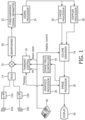
- FIGURE 1 an ultrasound system constructed in accordance with the principles of the present invention is shown in block diagram form.
- Two transducer arrays 10a and 10b are provided for transmitting ultrasonic waves and receiving echo information.
- the arrays shown are two dimensional arrays of transducer elements capable of providing 3D image information although an implementation of the present invention may also use one dimensional arrays of transducer elements which can be used to produce 2D (planar) images and/or deliver ultrasonic energy to a region of interest.
- Another alternative is to mechanically steer a one-dimensional array to produce the effect of an electronically steered 1D or 2D array.
- the transducer arrays in this implementation are coupled to microbeamformers 12a and 12b which control transmission and reception of signals by the array elements and in particular the steering and focusing of ultrasonic beams for imaging and therapy.
- Microbeamformers are capable of at least partial beamforming of the signals received by groups or "patches" of transducer elements as described in US Pats. 5,997,479 (Savord et al. ), 6,013,032 (Savord ), and 6,623,432 (Powers et al. ).
- Signals are routed to and from the microbeamformers by a multiplexer 14 by time-interleaved signals.
- transducer drive circuitry capable of higher output power levels may be employed.
- the multiplexer is coupled to a transmit/receive (T/R) switch 16 which switches between transmission and reception and protects sensitive input circuitry of the main beamformer 20 from high amplitude transmit signals.
- T/R transmit/receive
- the transmission of ultrasonic beams from the transducer arrays 10a and 10b under control of the microbeamformers 12a and 12b or other drive circuitry is directed by the transmit controller 18 coupled to the T/R switch, which receives input from the user's operation of the user interface or control panel 38.
- the partially beamformed echo signals produced by the microbeamformers 12a, 12b are coupled to a main beamformer 20 where partially beamformed signals from the individual patches of elements are combined into a fully beamformed signal.
- the main beamformer 20 may have 128 channels, each of which receives a partially beamformed signal from a patch of 12 transducer elements. In this way the signals received by over 1500 transducer elements of a one- or two-dimensional array can contribute efficiently to a single beamformed signal.
- the beamformed signals are coupled to a nonlinear echo processor (or fundamental/harmonic signal separator) 22.
- the processor (or separator) 22 acts to separate (linear) echo signals arising from tissue structures from those (nonlinear) arising from VARs, thus enabling the identification of the strongly nonlinear echo signals returned from VARs.
- the processor 22 may operate in a variety of ways such as by bandpass filtering the received signals in fundamental frequency and harmonic frequency bands, or by processes known as pulse inversion harmonic separation, or power-modulation, which are also able to cancel tissue echoes while preserving VAR echoes, even in the fundamental band.
- Signal separators can be used to distinguish between linear and non-linear signals or fundamental and harmonic signals.
- a suitable nonlinear/linear signal separator is shown and described in international patent publication WO 2005/074805 (Bruce et al. ).
- the separated signals are coupled to a signal processor 24 where they may undergo additional enhancement such as speckle removal, signal compounding, and noise elimination.
- the processed signals are coupled to a B mode processor 26 and a Doppler processor 28.
- the B mode processor 26 employs amplitude detection for the imaging of structures in the body such as muscle, organs or tissue.
- B mode images of structure of the body may be formed in either the nonlinear mode or the linear mode.
- Tissues in the body and VARs both return both types of signals and the relatively strong nonlinear returns of VARs enable VARs to be clearly segmented in an image in most applications.
- the Doppler processor processes temporally distinct signals from tissue and blood flow for the detection of motion of substances in the image field including VARs.
- the structural and motion signals produced by these processors are scan converted and coupled to a volume renderer 34, which produces image data of tissue structure, flow, or a combined image of both characteristics.
- the volume renderer 34 will convert a 3D data set into a projected 3D image as viewed from a given reference point as described in US Pat. 6,530,885 (Entrekin et al. ) As described therein, when the reference point of the rendering is changed the 3D image can appear to rotate in what is known as kinetic parallax. This image manipulation is controlled by the user as indicated by the Display Control line between the user interface 38 and the volume renderer 34. Also described by Entrekin et al. is the representation of a 3D volume by planar images of different image planes, a technique known as multiplanar reformatting (MPR).
- MPR multiplanar reformatting
- the volume renderer 34 can operate on image data in either rectilinear or polar coordinates as described in US Pat. 6,723,050 (Dow et al. )
- the 2D or 3D images are coupled from the volume renderer to an image processor 30 for further enhancement, buffering and temporary storage for display of static or live 2D MPR or 3D
- a graphics processor 36 is coupled to the image processor 30 which generates graphic overlays for display with the ultrasound images. These graphic overlays can contain standard identifying information such as patient name, date and time of the image, imaging parameters, and the like, and can also produce a graphic overlay of a therapy beam vector steered by the user as described below.
- the graphics processor receives input from the user interface 38.
- the user interface is also coupled to the transmit controller 18 to control the generation of ultrasound signals from the transducer arrays 10a and 10b in the therapy and imaging modes and hence the images produced by and therapy applied by the transducer arrays.
- the transmit parameters controlled in response to user adjustment include the MI (Mechanical Index) which controls the peak intensity of the transmitted waves, which is related to the acoustic pressure and cavitational effects of the ultrasounds, steering of the transmitted beams for image positioning and/or steering of a therapy beam as discussed below.
- a therapy control signal commands the transmit controller to operate the transducer array in the therapy or diagnostic imaging mode as described below.
- the transducer arrays 10a and 10b transmit ultrasonic waves into the cranium of a patient from one or both sides of the head, although other locations may also or alternately be employed such as the front of the head or the sub-occipital acoustic window at the back of the skull.
- the sides of the head of most patients advantageously provide suitable acoustic windows for transcranial ultrasound at the temporal bones around and in front of the ears on either side of the head.
- the transducer arrays In order to transmit and receive echoes through these acoustic windows the transducer arrays must be in good acoustic contact at these locations which may be done by holding the transducer arrays in acoustic coupling contact against the head with a headset.
- Suitable headsets for cranial ultrasound transducers are described in international patent publication no WO 2008/017997 (Browning et al. ), US pat. pub. no. US 2012/0083718 (Alleman et al. ), and US pat. pub. no. US 2011/0251489 (Zhang et al. ), for instance.
- the ultrasound system of FIGURE 1 is used to apply two types of VAR-mediated ultrasound therapy concurrently, high acoustic pressure therapy directed at an occlusion to promote the lysis of a blood clot and low acoustic pressure therapy which provides beneficial effects to surrounding microvasculature, the latter being directed to promote microvascular reperfusion.
- An implementation of the present invention provides a means for achieving a recanalization of occluded major feeding arteries such as the MCA as well as reperfusion of the microvasculature surrounding the occlusion.
- acoustic-pressure levels will stimulate VAR activity in different ways.
- these ranges of pressure levels are differentiated, for each VAR type and size, at a given frequency, and by the nature of acoustic response from the VARs when exposed to these acoustic stimulations.
- Different thresholds exist which are useful in the determination of these ranges. These thresholds are determined by the appearance of certain frequency components in spectra of echoes scattered by the VARs. A first very low threshold exists, below which VARs only experience negligible oscillation. Below this threshold VAR oscillations are very small and have no therapeutic benefit for stroke treatment.
- VARs are not disrupted, their echo spectra do not contain sub-harmonic or ultra-harmonic components (i.e., odd multiples of the sub-harmonic frequency) and VARs can remain present within the ultrasound beam for a long time.
- a second low threshold can be identified, above which echo signals from VARs start exhibiting sub-harmonic and ultra-harmonic components in their frequency spectra. Above the second threshold, the regime is sometimes referred to as stable cavitation, and will be referred to here as mid acoustic pressure. At these levels, VARs may gradually disappear from the region under ultrasound exposure due to gradual escape of the gas from the VARs' envelope.
- VAR oscillations are relatively small but have been shown to promote reperfusion and thus to offer some therapeutic benefits.
- a third threshold exists, characterized by the appearance of broadband noise within the frequency spectra of echo signals from VARs, above which VARs exhibit inertial cavitation. These frequency components, which may be measured in frequency bands outside multiples of the fundamental and sub-harmonic frequencies, are associated with more rapid disappearance of the VARs.
- the onset of inertial cavitation is associated with a rupture of VAR envelopes, where the gas body liberated continues to oscillate in response to ultrasound wave, for a duration determined by the dissolution time of the gas in the surrounding medium. These levels are referred to herein as high acoustic pressure levels.
- the acoustic pressure levels applied to induce a response can be determined in relation to a tissue (e.g., lesion) volume of roughly spherical shape, with a radius r. Certain dimensions, for example, can be estimated for an infarct region in which low acoustic pressure levels are provided to promote reperfusion.
- the infarct volume can range from about 10 to 200 cm 3 , or from about 20 to 100 cm 3 , or from about 40 to 60 cm 3 .
- the infarct volume can have minimal, nominal, and maximal dimensions of 10, 50, and 200 cm 3 , respectively.
- a diameter of the area to be treated can range from about 2.5 to 7.5 cm, or from about 3.5 to 6.5 cm, or from about 4.5 to 5.5 cm. In one example, the diameter can have minimal, nominal, and maximal dimensions of 2.7, 4.6, and 7.3 cm, respectively.
- An area to be treated can range from about 5.5 to 42 cm 2 , or from about 10 to 30 cm 2 , or from about 15 to 20 cm 2 . In one example, the area can have minimal, nominal, and maximal dimensions of 5.6, 16.4, and 41.3 cm 2 , respectively. For promoting recanalization of an occluded region with mid/high acoustic pressure, different dimensions can be used.
- a diameter of a region with an occlusion can range from about 0.2 to 2 cm, or from about 0.5 to 1.5 cm, or from about 0.7 to 1.1 cm. In one example, the diameter can have minimal, nominal, and maximal dimensions of 0.2, 0.8, and 2 cm, respectively.
- the area to be treated can range from about 0.03 to about 3.1 cm 2 , or from about 0.3 to 2 cm 2 , or from about 0.7 to 1.2 cm 2 . In one example, the area can have minimal, nominal, and maximal dimensions of 0.03, 0.5, and 3.1 cm 2 , respectively. Ranges for treatment time can also be optimized for a given treatment application.
- treatment duration can range from about 15 to 120 minutes, or from about 30 to 90 minutes, or from about 45 to 75 minutes.
- the treatment duration can be a minimal, nominal or maximal duration of 15, 60, or 120 minutes, respectively.
- Pulse durations for the mid/high acoustic pressure can be a minimal, nominal or maximal duration of 0.01, 20, or 500 milliseconds, respectively.
- Pulse durations for the low acoustic pressure can range from about 0.01 to about 10000 milliseconds, from about 100 to about 5000 milliseconds, or from about 750 to 2500 milliseconds.
- the pulse duration can be a minimal, nominal or maximal duration of 0.01, 1000, or 10000 milliseconds, respectively.
- an off-time for replenishment ranging from minimally greater than 0 to 20 seconds, or from about 2 to 15 seconds, or from about 4 to 10 seconds.
- the time for replenishment can be minimally greater than 0 seconds, nominally 5 seconds, and maximally 20 seconds.
- Preferred treatment duration can range from about 30 to 90 minutes, or from about 45 to 75 minutes, or from about 55 to 65 minutes.
- the treatment duration can be a minimal, nominal or maximal duration of 30, 60, or 90 minutes, respectively.
- Pulse durations for the mid/high acoustic pressure can range from about 0.1 to 100 milliseconds, or from about 5 to 50 milliseconds, or from about 15 to 35 milliseconds.
- the pulse duration for the mid/high acoustic pressure can be a minimal, nominal or maximal duration of 0.1, 20, or 100 milliseconds, respectively.
- Pulse durations for the low acoustic pressure can range from about 1 to 5000 milliseconds, from about 300 to 2500 milliseconds, or from about 500 to 1500 milliseconds.
- pulse duration for the low acoustic pressure can be a minimal, nominal or maximal duration of 1, 1000, or 5000 milliseconds, respectively.
- There may also be an off-time for replenishment ranging from about 1 to 10 seconds, or from about 2 to 8 seconds, or from about 3 to 6 seconds. In one example, an off-time for replenishment can be minimally greater than 1 seconds, nominally 5 seconds, and maximally 10 seconds. It is further noted that any duration times and/or dimensions between the minimal and maximal values described above can also be selected for a given treatment.
- VARs which operate in combination with the transducer of the system when submitted to the applied ultrasound waves at the required acoustic pressures.
- Vascular acoustic resonators include any component capable of converting acoustic pressure in a propagation-medium into micron-size displacements, capable of applying strain onto blood clots or vessel walls, also with micron-size deformation amplitude.
- VARs include gas-filled microvesicles, i.e. vesicles of nano- or micron-size comprising a stabilizing envelope containing a suitable gas therein.
- the formulation and preparation of VARs is well known to those skilled in the art, including, for instance, formulation and preparation of: microbubbles with an envelope comprising a phospholipid, as described e.g. in WO 91/15244 , US Pat. 5,686,060 (Schneider et al. ) and WO 2004/069284 ; microballoons with an envelope comprising a polymer, as described e.g. in US Pat.
- the stabilizing envelope comprises an amphiphilic material, more preferably a phospholipid.
- Preferred phospholipids include esters of glycerol with one or preferably two (equal or different) residues of fatty acids and with phosphoric acid, wherein the phosphoric acid residue is in turn bound to a hydrophilic group.
- Other preferred phospholipids include phosphatidic acids, i.e. the diesters of glycerol-phosphoric acid with fatty acids.
- Particularly preferred phospholipids are fatty acids diesters of phosphatidylcholine, ethylphosphatidylcholine, phosphatidylglycerol, phosphatidic acid, phosphatidylethanolamine, phosphatidylserine, phosphatidylinositol or of sphingomyelin.
- Polymer-modified phospholipids, including pegylated phospholipids can also be advantageously employed for forming the stabilizing envelope of microbubbles. Any biocompatible gas, gas precursor or mixture thereof may be employed to fill the above microvesicles. Fluorinated gases are preferred, in particular perfluorinated gases.
- Particularly preferred gases are SF 6 , C 3 F 8 , C 4 F 10 or mixtures thereof, optionally in admixture with air, oxygen, nitrogen, carbon dioxide or mixtures thereof, as described for instance in US 6,881,397 or US 5,556,610 .
- the components forming the stabilizing envelope of the VARs can be stored as a dry residue in contact with the desired gas(es).
- Microvesicles are typically prepared by contacting the dry residue in the presence of the gas(es) with an aqueous carrier (e.g ., saline or glucose solution) under gentle shaking, thus obtaining an aqueous suspension of microvesicles.
- the microvesicle suspension is then typically administered by injection, preferably intravenously.
- the example for explaining features of the present invention further provides an interval for allowing replenishment of fresh VARs at the site of the occlusion following their rapid disappearance when subjected to the ultrasound waves at mid/high-pressure and thus optimizes the efficacy of ultrasound treatment and enables visualization of the treatment site to be updated.
- a 2D array transducer is used to electronically steer therapy and imaging beams to the site of the occlusion and over the surrounding volumetric region and to image the therapy site in both two and three dimensions.
- VAR mediation is provided by a systemically infused dose of a VAR such as gas-filled microvesicles, preferably gas-filled and having a phospholipid-based stabilizing envelope, circulating throughout the entire blood stream and capable of reaching the region to be treated via residual and collateral flow.
- VARs are either continuously infused, or delivered via one or multiple bolus injections, which can be administered before and/or in the course of the ultrasound insonation.
- a priori knowledge of the microstructure characterization data which would at a minimum include the ultrasonic pressure thresholds at which the infused microstructures oscillate and cavitate stably and at which they undergo inertial cavitation, together with a parameter which characterizes the VAR lifetime in the bloodstream, will enable the treatment to be effectively initiated and controlled.
- Knowledge of systemic VAR concentrations i.e ., in terms of numbers of VARs/ml of blood
- bolus injection and infusion may also be required so as to make sure that a minimum required concentration is present in the target region for adequate lysis and microvascular reperfusion. These parameters can be determined empirically in vitro for different VARs and/or different parameters of insonation.
- Treatment methods can be formulated which (i) target the main occlusion with the ultrasound beam at mid/high-pressure levels during a certain amount of time during the treatment, (ii) target the surrounding volume with ultrasound waves at low pressure levels during a certain amount of time during the treatment, and (iii) stop the application of therapeutic ultrasound completely for a certain amount of time to permit an influx of fresh VARs for imaging and further therapy.
- target the main occlusion with the ultrasound beam at mid/high-pressure levels during a certain amount of time during the treatment
- target the surrounding volume with ultrasound waves at low pressure levels during a certain amount of time during the treatment and
- stop the application of therapeutic ultrasound completely for a certain amount of time to permit an influx of fresh VARs for imaging and further therapy.
- a cavitation detector and monitor as described in international patent pub. no. WO 2012/042494 is used to monitor VAR oscillation in the target region, to non-invasively determine if the VARs are oscillating dominantly in their required mode (i.e., stable cavitation, inertial cavitation, etc.) and to adjust the ultrasound exposure correspondingly if they are not.
- Ultrasound imaging (operating at a very low acoustic pressure which causes no VAR destruction) is preferably employed to image VAR reperfusion during pauses in the treatment, to observe the progress of clot lysis, and to observe the presence and flow of VARs to the site of the occlusion and surrounding microvasculature. Therapeutic ultrasound exposure is resumed once a sufficiently high amount of VARs have re-perfused the target region after VAR destruction during the higher level ultrasound exposure.
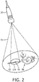
- FIGURE 2 illustrates an ultrasound probe producing dual therapy levels of ultrasound pressure in accordance with the present invention. Shown projecting from the probe 10 are outlines of two regions 32 and 122 of volumetric ultrasound insonation.
- the inner conical region 122 is a region in which ultrasound waves with mid- or high-level acoustic pressure are applied to produce cavitation at a site 54 of a blood clot which is occluding a vessel 52.
- the blood supply is blocked by the occlusion 54 as indicated by the cross-hatched supply portion of the vessel 52.
- the acoustic pressure in the region 122 is high enough to produce inertial cavitation of the VARs in the vessel adjacent to the occlusion.
- microvasculature indicated at 56 Downstream from the occluded blood vessel 52 is microvasculature indicated at 56 which is supplied with blood from the vessel 52, in normal blood flow conditions, or via other collateral paths.
- This microvasculature in the tissue surrounding the occluded blood vessel is subjected to low acoustic pressure in region 32 by the probe 10, which allows the maintenance of a substantial amount of intact VARs in the microvasculature at the site of treatment. It is the application of this low acoustic pressure in combination with the VARs which is intended to promote microvasculature reperfusion as the higher acoustic pressure of the inner region 122 in combination with the VARs promotes lysis of the blood clot 54.
- the dual therapy levels can be delivered at different time intervals.
- a transmit controller in the ultrasound system and coupled to control the transmission of ultrasound by the array transducer is configured (1) to direct ultrasound waves at mid/high acoustic pressure to the site of an occlusion during a first therapy time interval and (2) to direct ultrasound waves at low acoustic pressure levels to a region surrounding the site of the occlusion during a second reperfusion stimulation time interval.
- the transmit controller further controls an array transducer to direct an ultrasound wave at mid/high acoustic pressure to the site of an occlusion where VARs are present to stimulate clot lysis at the site during a first therapy time interval, and controlling an array transducer to direct an ultrasound wave at a low acoustic pressure to a region surrounding the site of the occlusion to stimulate microvascular reperfusion during a stimulation time interval.
- a peak acoustic pressure transmitted during the first therapy time interval is greater than a peak acoustic pressure transmitted during the second reperfusion stimulation time interval.
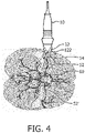
- FIGURE 4 is an anatomical illustration of the dual acoustic pressure therapy technique of the present invention.
- the probe 10 is seen located at the acoustic window of the temple of the head where it insonifies the brain 60 from the ipsi- or contra-lateral side of the occlusion.
- the narrow hourglass-shaped profile 122 of high pressure is seen to be focused at the depth of a blood clot 54 in the middle cerebral artery (MCA) 52.
- MCA middle cerebral artery
- the broader dashed line profile 32 delineates the region in which low pressure insonation is provided to the surrounding microvasculature of the brain.
- the MCA 52' on the other side of the brain is illustrated as containing a continuous flow of VARs in the bloodstream, indicated by the small white dots in the drawing.
- the ultrasound beam can cover the necessary region of interest by moving it mechanically and/or electronically, defocusing it into a broader beam, or both.
- the same probe 10 can further be used for diagnosis by incorporating both transmit and receive capabilities for imaging or Doppler processing.
- the clot can be located through imaging, and clot lysis and perfusion evaluated by imaging the same VARs as are used for therapy.
- the transducer array 10a, 10b is preferably not employed in a conventional ultrasound probe as shown in FIGURES 2 and 4 , but is built into a headset and placed on the temporal bone window of a stroke victim as shown in FIGURE 6 .
- Preferably two transducer arrays are used so that the headset will position them against the temporal bone acoustic windows on both sides of the skull 100.
- the acoustic fields of the arrays are generally oriented towards the MCA region of the brain and a clot can be treated on either side of the brain, using the array located on the ipsi- and/or on the contra-lateral side of the occlusion to be treated.
- the low pressure regions of the arrays are indicated by regions 102 and 104, and the arrows 110 and 112 indicate the mid/high pressure beam regions which are aimed at an occlusion.
- VARs would be administered intravenously and the location of the clot would be determined by MR, CT, or ultrasound.
- the same transducer array 10a, 10b is used for diagnosis and therapy it can be used to locate the clot itself via the absence of blood flow and/or perfusion distal to the site of the clot occlusion, using low-MI ultrasound contrast imaging or Doppler techniques already known.
- the mid/high-pressure beams produced by the 2D matrix array transducer (a two-dimensional array transducer with attached microbeamformer or driven by high power drive circuitry) is then aimed at the general clot location and the lower pressure microvascular reperfusion beams flood the surrounding volumetric region at risk.
- Typical penetration distance requirements are approximately 3-10 cm from the skull surface.
- Typical 3D beam steering angle requirements are approximately up to ⁇ 27°, and focal zone size requirements are approximately 5-10mm in diameter.
- the ultrasonic output of the array transducer should be sufficient to generate both mid-pressure and low-pressure pulses inside the brain, further accounting for temporal bone attenuation, which attenuates the beam by approximately 75%.
- an in-situ pressure of more than 140 kPa is needed for a phospholipid-based gas-filled microbubble to sustain stable cavitation in the brain, and more than 250 kPa is needed to achieve inertial cavitation.
- FIGURE 7 illustrates, in a schematic way, the conversion of acoustic pressure from an ultrasound wave 123 applied on a VAR 125a, 125b located within a vessel lumen 124, going from a compression phase 125a to an expansion phase 125b, to apply strain to the surface of a blood clot 126.
- This deformation is localized in the immediate vicinity of the VAR, does not occur elsewhere and causes a massaging effect believed to be associated with the promotion of flow restoration.
- the high acoustic pressure levels facilitate clot lysis and vessel recanalization while minimizing detrimental bioeffects. These pressures are applied while focusing the ultrasound beam directly at the main clot or occlusion. Low acoustic pressures induce microvascular reperfusion with significantly lower microbubble disappearance rates than those at mid/high acoustic pressure. These low acoustic pressures are applied while focusing or directing the ultrasound beam in the volume surrounding the main occlusion to facilitate microvascular reperfusion, and allow the blood flow to replenish the various vessels in the proximity of the clot with additional microbubbles before continuing treatment with the higher pressure pulses. For instance, the low acoustic pressures can be applied by sequentially stepping differently steered ultrasound beams around the region surrounding the site of the occlusion.
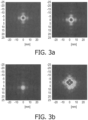
- FIGURES 3 and 5 illustrate spatial and temporal characteristics of exemplary VAR-mediated ultrasound treatment procedures in accordance with the present invention.
- FIGURES 3a, 3b , 3c and 3d illustrate spatial distributions of pulsed ultrasound therapy beams in the treatment region in accordance with one implementation of the present invention.
- the left image of each pair of images shows the instantaneous pulse at a given time in the pulse sequence and the right image shows the accumulated pulse energy of the sequence.
- the transducer array transmits a plurality of differently steered high pressure pulses directed at the site of the occlusion, followed by a plurality of differently steered low pressure pulses directed at the microvasculature surrounding the occlusion site.
- FIGURE 3a a first high pressure pulse is transmitted toward the occlusion site. This pulse is followed by three more high pressure pulses steered adjacent to the first pulse as illustrated by the four dark pulses at the center of the right image in FIGURE 3b , in order to maximize the target area insonation on the clot. These four high pressure pulses are followed by low pressure pulses steered (e.g. in sequential steps) around the region exposed to high pressure pulses as shown in FIGURE 3b . In the right image it is seen that four low pressure pulses have been transmitted around the region exposed to high pressure pulses, starting at the three o'clock position and continuing to the six o'clock position by the time of FIGURE 3b .
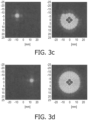
- This sequence of low pressure pulses continues in ever-expanding circles around the previous pulse locations as shown in FIGURE 3c , where a second ring of low pressure pulses is nearing completion.
- Other, non-circular insonation patterns i.e. raster scan pattern, random, outside-in, etc.
- the beam patterns of the low- and mid/high-pressure beams may be different, for example with a broader spatial distribution for the low-pressure beams than for the mid/high-pressure beam. The sequence continues until the entire region exposed to the low-pressure pulses has been insonified as shown in FIGURE 3d .
- the spatial sequencing of relatively narrow pulses as opposed to a full floodlight insonation of the regions enables the practice of the present invention with the transducer arrays of many imaging probes without the need for mechanical scanning or a specially designed therapy/imaging probe by taking advantage of the probe's beam focusing and steering capabilities.
- the pulsing can be performed rapidly enough to provide the necessary pressure for therapy while avoiding probe heating and the buildup of hazardous energy levels in the body in most instances.
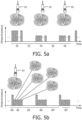
- FIGURES 5a and 5b illustrate two other ultrasound treatment procedures in accordance with the present invention.
- the taller, dark bars in each drawing represent high level therapy pulses for clot lysis and the shorter, lighter bars represent low level therapy pulses for microvascular reperfusion stimulation.
- the treatment procedure of FIGURE 5a begins with a sequence 70 of high pressure pulses directed at a clot to produce clot lysis. This is followed by a period 72 during which no therapeutic ultrasound waves are applied to allow microbubbles to replenish at the site of treatment.
- imaging can be done at diagnostic levels during this time. Imaging at very low levels of mechanical index will have a minimal effect on VAR replenishment and enables the clinician to visualize the site of the therapy and assess the progress of clot lysis.
- Imaging is performed in a time-interleaved manner with ultrasonic therapy as described in international patent pub. no. WO 2008/017997 (Browning et al. )
- low level ultrasound pressure is delivered to the region surrounding the site of the occlusion (and may also overlap the occlusion site) to stimulate reperfusion in the surrounding microvasculature. Since this insonation is at low acoustic pressure, VAR replenishment can also occur during this interval.
- Interval 76 is another interval of no therapy to allow for maximal microbubble replenishment and, if desired, acquisition of one or more new 2D or 3D images of the treatment site.
- Another interval 78 of the delivery of low level ultrasound pressure to the surrounding microvasculature After interval 78 the sequence repeats with another interval of high acoustic pressure therapy pulses.
- the following parameters can be used for the treatment procedure of FIGURE 5a , in combination with phospholipid-based gas-filled microbubbles: an ultrasonic frequency of 1 MHz for therapy pulses, a mid/high pressure level of about 200 kPa and a low pressure level of about 100 kPa (in-situ), a pulse duration of 2 milliseconds (msec) for each therapy pulse, and a microbubble replenishment interval of one second.
- FIGURE 5b illustrates another treatment procedure in which higher pressure therapy pulses are immediately followed by lower pressure pulses.
- One or more high pressure pulses are delivered to the site of an occlusion at time 80, followed by a plurality of differently steered low pressure pulses during the following interval 82.
- Each of the low pressure pulses are directed in a different direction through the surrounding microvasculature as illustrated in FIGURE 3 , thereby insonifying the full region subjected to the low pressure with a plurality of differently steered beams.
- the low pressure interval 82 is followed by a period 84 of no therapy pulses for microbubble replenishment during which imaging may optionally be performed.
- the sequence then repeats with another interval 86 of differently steered high pressure and low pressure pulses followed by another microbubble replenishment/imaging interval 84'.
- the sequence then continues in this manner until a satisfactory recanalization of the vessel is achieved, preferably with a substantially complete removal of the blood clot, which may optionally be followed by continued microvascular reperfusion stimulation.
- Typical parameters used for the treatment procedure of FIGURE 5b are an ultrasonic frequency of 1 MHz for therapy pulses, a mid/high pressure level of 200 kPa or greater and a low pressure level of 80 kPa or less (in-situ), , a pulse duration of 200msec for high pressure pulses and 950msec for each low pressure therapy pulse, and a microbubble replenishment interval of six seconds.
- the replenishment interval 72 or 84 may be omitted altogether, especially if ultrasound waves with low pressure pulses allows maintenance of a substantial amount of VAR at the site of therapeutic treatment, or if the successive pulses are sufficiently spaced apart in time, allowing the replenishment to occur during the application of ultrasound waves.
- an array transducer can be operated to produce floodlight insonation of the different regions of insonation.
- a high pressure beam can be formed and aimed at an occlusion to cause clot lysis, and a larger low pressure floodlight beam which insonifies the surrounding microvasculature can be formed and transmitted to stimulate microvascular reperfusion with a single broad beam as illustrated in FIGURE 2 .
- the transducer arrays 10a and 10b transmit ultrasonic waves into the cranium of a patient from opposite sides of the head, although other locations may also or alternately be employed such as the front of the head or the sub-occipital acoustic window at the back of the skull.
- the sides of the head of most patients advantageously provide suitable acoustic windows for transcranial ultrasound at the temporal bones around and above the ears on either side of the head.
- Suitable headsets for cranial ultrasound transducers are described in previously mentioned international patent publication no WO 2008/017997 (Browning et al. ), US pat. pub. no. US 2012/0083718 (Alleman et al. ), and US pat. pub. no. US 2011/0251489 (Zhang et al. ), for instance.
- the aforementioned Browning et al. application shows a headset with two transducer arrays acoustically coupled to opposite sides of the head.
- Each transducer array can image the side of the brain closest to the array to search for a thrombus, then deliver acoustic energy to treat a located thrombus.
- a thromboembolic occlusion that causes stroke most often occurs in the region of the proximal middle cerebral artery (MCA) that is very close to the brain midline. Less frequently, such an occlusion can occur much closer to the ipsilateral temporal bone, in the distal MCA or other regions away from the brain midline.
- MCA proximal middle cerebral artery
- VARs generally flow toward the occluded region in the blood stream and, due to the geometry of the brain and its vasculature, the blood flow in the MCA is directed from the brain midline toward the ipsilateral temporal bone.
- the flow of fresh VARs to the site of an occlusion is generally toward the temple where the headset transducer closest to the occlusion is located.
- acoustic waves from the ipsilateral transducer can have the effect of opposing the desired flow of fresh VARs toward the thrombus.
- VARs In order for effective thrombus dissolution, it is desirable for VARs to be present in the treatment region, move close to the surface of the occluding thrombus, or even penetrate into the occluding thrombus itself. In accordance with the principles of the present invention, this is achieved or, minimally, enhanced by using the mechanism of acoustic radiation force, which acts on the VARs by pushing them along in the direction of the ultrasound propagation. Because of the vessel geometry in the brain, in order for the acoustic radiation force to push VARs into the occlusion, it is necessary for the ultrasound "pushing" array to be placed on the contralateral temporal bone.
- the contralateral array produces ultrasound beams that propagate from the contralateral to the ipsilateral side, thereby pushing the VARs toward the occlusion.
- the radiation force can not only push VARs to move toward the initial occlusion clot, but also push them closer to the clot or even inside the clot for more effective lysis.
- the radiation force may help VARs move (with the synergistic assistance of pulsatile blood pressure, possibly in an oscillating, forward, peristaltic motion) into the entire occlusive region, including the initial occlusion site and any subsequently occluded or resultant ischemic downstream vascular space.
- the pulsatile blood pressure can push VARs closer to the clot surface, as well as to move into the space of the downstream vascularity. Accordingly it is desirable to be able to promote the flow/motion of new resonators both to the initial occlusion site as well as its downstream vascular space to enhance the lysis effect of VARs that are close to or inside the occluded vascular space.
- FIGURE 8 This is illustrated in FIGURE 8 , in which the ultrasound system of FIGURE 1 is used to apply sonothrombolysis therapy and concurrently urge a flow of fresh VARs to the therapy site in a time interleaved manner.
- the transducer arrays 100a, 100b are preferably not employed in conventional ultrasound probes, but are custom probes built into a headset and placed on the temporal bone windows of a stroke victim as shown in FIGURE 8 .
- the two transducer arrays of the headset will position themselves against the temporal bone acoustic windows on both sides of the skull 1000 as shown in the illustration. When positioned this way, the acoustic fields of the arrays are generally oriented towards the MCA region toward the center of the brain.
- the ipsilateral side where a clot 1160 is located is within the therapy beam steering region 1020 of transducer array 100a.
- a therapy beam 1100 can be steered in three dimensions within this region 1020 and directed at a thrombus 1160 for therapy as shown in the illustration.
- a similar region 1040 exists in front of the contralateral transducer 100b on the other side of the head.
- the ultrasonic energy produced by the contralateral transducer 100b is not at a therapeutic level but at a lower level which produces ultrasonic energy waves 1120 which are sufficient to promote a gentle acoustic radiation force on VARs in the blood vessel 1140 leading to the thrombus 1160.
- the contralateral transducer array 100b could be used for therapy. But the greater distance from the contralateral temporal bone to the occlusion 1016 as compared to that from the ipsilateral temporal bone to the occlusion means that ultrasound pulses with greater pressure amplitude would be needed to be transmitted for therapy from the contralateral side than from the ipsilateral side, to account for the increased signal attenuation due to the longer beam path length.
- the greater pressure amplitude implies the use of an ultrasound array with a larger aperture for producing a high intensity focused beam reaching a greater distance from the array.
- the effective aperture of the array is typically limited by the size of the particular temporal acoustic window.
- contralateral ultrasound beams to generate the acoustic radiation force needed to push the VARs towards the occluding thrombus, and ipsilateral beams for the delivery of the therapeutic ultrasound pulses to actually lyse the clot.
- Various electronic configurations can be used to actuate the opposing transducer arrays. Both arrays can be driven alternatively by multiplexing the same electronics, or the array (operated for imaging and radiation force) on the contralateral side and the array (operated for therapy) on the ipsilateral side may be driven simultaneously by two separate signal generators and power amplifiers.
- an IV would be started to later deliver the VARs and the location of the clot could be determined by MR, CT, or ultrasound imaging.
- the VAR mediation can be provided by a systemically infused dose of a VAR contrast agent circulating throughout the entire blood stream and capable of reaching the occluded region via residual and collateral flow.
- the VARs will remain substantially intact at low ultrasound pressure levels, will provide increased clot lysis capability at mid-pressure levels, and will replenish the treatment region throughout the entire sonothrombolysis therapy procedure during the periods of non/low amplitude insonification.
- the same transducer array 100a, 100b When the same transducer array 100a, 100b is used for diagnosis and therapy it can be used to locate the clot itself via the absence of blood flow and/or perfusion distal to the site of the clot occlusion, using the low-MI ultrasound contrast imaging or Doppler techniques already in use.
- mid- or high-pressure beams are produced by the ipsilateral array transducer which are aimed at the general clot location.
- Typical penetration distance requirements are approximately 3-10 cm from the skull surface.
- Typical 3D beam steering angle requirements are approximately up to ⁇ 27°, and focal zone size requirements for treatment are approximately 5-10mm in diameter.
- the ultrasonic output of the array transducer should be sufficient to generate both mid-pressure and low-pressure pulses inside the brain, further accounting for temporal bone attenuation, which attenuates the beam by approximately 75%.
- an in-situ pressure of approximately 140 to 250 kPa is needed for a phospholipid-based microbubble agent to undergo stable cavitation in the brain.
- the transmission of therapy beams by the ipsilateral transducer array is interrupted to allow a fresh supply of microbubbles to flow to the thrombus.
- the contralateral transducer array is actuated to transmit low acoustic pressure levels toward the therapy site, e.g., between approximately 80 and 140 kPa, with the effect of providing acoustic pushing pulses which urge fresh microbubbles toward and into the thrombus.
- This low level ultrasonic stimulation can also provide the beneficial effect of inducing microvascular reperfusion as described herein.
- the low level ultrasound used to urge the microbubbles toward the clot can also be used to image the site of the clot from the contralateral side of the head if desired.
- Ultrasound imaging is preferably employed by either transducer array to image microbubble reperfusion during pauses in the treatment, to observe the progress of clot lysis, and to observe the presence and flow of microbubbles to the site of the occlusion and surrounding microvasculature.
- Therapeutic ultrasound exposure is resumed once a sufficiently high amount of microbubbles have re-perfused the target region after microbubble destruction with the stimulus of the contralateral acoustic radiation force.
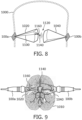
- FIGURE 9 is an anatomical illustration of stroke sonothrombolysis therapy being applied from an acoustic window at the left side of the head which is alternated with acoustic radiation force from the other side of the head to urge microbubbles 1140 toward a cranial thrombus 1160.
- the transducer probe 100a used for therapy in this example is seen located at the acoustic window of the temple on the left side of the head where it insonifies the brain 1010 from the ipsilateral side where the thrombus is located.
- the narrow hourglass-shaped energy profile 1020 of mid- to high-energy ultrasound is seen to be focused at the depth of the blood clot 1160 in the middle cerebral artery (MCA).
- transducer probe 100b Located at the acoustic window of the right temple of the head, the contralateral side, in this example, is another transducer probe 100b.
- the broader energy profile 1040 produced by transducer probe 100b provides low energy acoustic radiation force toward the ipsilateral MCA, urging the VARs 1140 toward the blood clot 1160.
- high energy clot-disrupting therapy and low energy radiation force urging of the VARs are alternated periodically, as it can be seen that the pressure waves from the two transducer probes are directed in opposite directions and the resulting radiation forces would otherwise oppose each other.
- Pressures below these levels are those that may also stimulate microvascular reperfusion but are less effective at 1MHz to push microbubbles towards the thrombus.
- microbubbles of different sizes respond differently to various pressures, and lower pressures will destroy fewer microbubbles while higher pressures will destroy more.
- Other pulse types such as chirps or amplitude modulated tone-bursts may also be employed for producing pulsatile radiation forces which are effective for pushing microbubbles of different sizes.
- the present invention provides an ultrasonic sonothrombolysis system that includes two array transducers each acoustically coupled to an acoustic window on opposite sides of the head of a subject; and a transmit controller, coupled to control the transmission of ultrasound by the two array transducers, and operated to cause an ipsilateral one of the array transducers to direct high energy ultrasound to the site of an occlusion and to cause a contralateral one of the array transducers to direct low energy ultrasound to a blood vessel supplying microbubbles to the site of the occlusion.
- the contralateral array transducer produces an acoustic radiation force for urging microbubbles toward the occlusion.
- the transmit controller can be further adapted to produce high energy and low energy ultrasound transmission by the two array transducers in a time-interleaved sequence.
- the transmit controller can further cause the ipsilateral array transducer to produce ultrasound which is narrowly focused at the occlusion, and cause the contralateral array transducer to produce ultrasound which is more broadly focused at the site of the occlusion and surrounding vasculature.
- the ipsilateral array transducer directs therapy beams to the site of an occlusion from one side of the head and the contralateral transducer directs an oppositely directed acoustic radiation force from the other side of the head.
- the acoustic windows can further include the temples on opposite sides of the head.
- the transmit controller can further cause one of the array transducers to perform ultrasound imaging of the site of the occlusion during periods of low energy ultrasound transmission.
- the transmit controller is further adapted to cause the ipsilateral array transducer to produce high energy insonification sufficient to cause inertial cavitation at the site of the occlusion and to cause the contralateral array transducer to produce low energy insonification sufficient to cause stable cavitation at the site of the occlusion.
- the transmit controller is adapted to produce high pressure insonification of at least 180kPa and low level pressure insonification of not greater than 140kPa.
- An example for explaining features of the present invention further provides a method of providing sonothrombolysis to a site of a vascular occlusion.
- the method can include controlling an ipsilateral array transducer which is acoustically coupled to one side of a head to direct high energy ultrasound to the site of an occlusion; and controlling a contralateral array transducer which is acoustically coupled to the other side of the head to direct low energy acoustic radiation force ultrasound to the site of the occlusion to stimulate flow of microbubbles toward the occlusion.
- the high energy and low energy ultrasound can be provided in a time-interleaved sequence.
- the controlling the ipsilateral array transducer to direct high energy ultrasound to the site of an occlusion can include producing ultrasound pressure levels which are at least capable of causing stable cavitation, and controlling the contralateral array transducer to direct low energy ultrasound to the site of the occlusion can include producing ultrasound pressure levels not greater than those capable of causing stable cavitation.
- the method can also include controlling the ipsilateral array transducer to cease production of high energy ultrasound during a microbubble replenishment interval, in which the contralateral array transducer produces acoustic pushing pulses during the microbubble replenishment interval.
- the method can include controlling one of the array transducers to perform diagnostic imaging of the site of the occlusion during the microbubble replenishment interval.
- the method can include controlling the ipsilateral array transducer to perform diagnostic imaging of the site of the occlusion during the microbubble replenishment interval.
- the high energy ultrasound is at a relatively low frequency
- the low energy ultrasound is at a relatively high frequency.
Description
- This invention relates to medical ultrasound systems and, in particular, to ultrasound systems which, in combination with vascular acoustic resonators, perform therapy for stroke victims.
- Ischemic stroke is one of the most debilitating disorders known to medicine. The blockage of the flow of blood to the brain can rapidly result in paralysis or death. Attempts to achieve recanalization through thrombolytic drug therapy such as treatment with tissue plasminogen activator (tPA) has been reported to cause symptomatic intracerebral hemorrhage in a number of cases. Advances in the diagnosis and treatment of this crippling affliction are the subject of continuing medical research.
- Use of ultrasound waves is an emerging non-invasive stroke treatment modality which is applied to help lyse blood clots causing vascular occlusion. According to certain treatments, gas-filled microvesicles or other vascular acoustic resonators (VARs) are systemically injected into the blood stream. The oscillation of the VARs in the ultrasound field helps disrupt the blood clots that cause heart attacks and stroke. These ultrasound-based treatments are also known in the art as sonothrombolysis or sonolysis. Recent studies have shown, however, that removal of the clot may not always restore nourishing blood flow to affected tissues. Furthermore, the present inventors have observed that, even when the clot continues to occlude the artery which is the source of blood flow to cells and tissue, ultrasound may nonetheless have a beneficial effect. The physiological properties behind these effects are not fully understood. Others have speculated that even when the clot is dissolved or broken up, capillaries of the vascular structure downstream from the location of the clot may still be occluded, possibly by microclots, small particles of fibrous material that may have preceded the clot or broken off from the clot and continue to block the flow of blood to the microvasculature. Others have also speculated that the microvasculature is occluded by neutrophils, white blood cells that have been stimulated by the ischemic condition to rush to the microvasculature as the body's response to the trauma, where they end up occluding the microvasculature. Still others have surmised that microvascular structures may be supplied with blood by paths from collateral arteries, so that some oxygenated blood may reach an ischemic region from alternate sources even when the major arterial conduit remains blocked. Regardless of the actual explanation of the underlying phenomena and their interplay, it is desirable to provide treatment of the occlusion in the major artery to provide the desired recanalization while concurrently promoting the flow of blood to affected microvasculature surrounding the occlusion to provide reperfusion of the capillary bed.
-
US 2010/160780 A discloses an ultrasonic diagnostic imaging system which utilizes one or more transducer arrays affixed to the head of a patient to diagnose and treat stroke victims. The transducer headset produces a two or three dimensional image of the vasculature inside the cranium, preferably assisted by a microbubble contrast agent. A vascular flow map is produced by the system which may be diagnosed for signs of a blood clot. If a blood clot is detected, a therapeutic beam is transmitted while the contrast agent is present to break up the blood clot by the disruption of microbubbles. The headset may also be used in a monitoring application to detect the recurrence of blood clots in a stroke victim. -
WO 2007/058668 A discloses an apparatus and a method to treat a patient sustaining cerebral ischemia or an ischemic stroke in the brain. The method supplies an ultrasound emitting device comprising a plurality of ultrasound transducers and emitting first ultrasound energy by the ultrasound emitting device, where that first ultrasound energy comprises first power. The method locates using the first ultrasound energy an occlusion disposed in one of the patient's cerebral blood vessels. The method then emits second ultrasound energy by the ultrasound emitting device, where that second ultrasound energy comprises second power, where the second power is greater than said first power. The method lyses the occlusion using the second ultrasound energy. - CLOTILDE BALUCANI ET AL, discloses in "Ultrasound- and Microspheres-Enhanced Thrombolysis for Stroke Treatment: State of the Art current and emerging applications of ultrasound and microspheres in stroke management including augmentation of systemic thrombolysis and implications for future reperfusion strategies.
- Furthermore, sonothrombolysis is an emerging non-invasive stroke treatment modality in which systemically injected VARs are insonified, and their resultant oscillation or rupture is used to lyse the clot causing the occlusion in acute ischemic stroke. Sonothrombolysis uses VARs oscillating in an ultrasound field to disrupt the blood clots that cause heart attacks and stroke. But there is an inherent problem in this treatment procedure, which is delivering a continuing flow of VARs to the site of the vascular obstruction. Since the clot is obstructing the flow in the vessel, the clot itself is compromising the delivery of new VARs to the site of the obstruction, and downstream from it. The greater the degree of flow obstruction, the smaller the supply of fresh VARs-containing blood to the clot. Accordingly it is desirable to be able to promote the flow of new VARs to the site of the clot despite the obstruction of the blood supply by the clot to facilitate enhanced interactions between the resonators and the clot to promote clot lysis.
- In accordance with an aspect of the present invention, an ultrasound stroke treatment system comprises the features of claim 1.
- The ultrasound stroke treatment system comprises a transducer which is capable of targeting an occlusion in the presence of vascular acoustic resonators (VARs) by applying ultrasound waves at mid- or high-acoustic pressure levels to promote clot lysis and vessel recanalization, and applying ultrasound waves at lower acoustic pressure levels over a wider area surrounding the occlusion to promote microvascular reperfusion in the surrounding area in the presence of VARs. The applications of lower and higher ultrasound pressure may be activated simultaneously or in a time-interleaved manner. For example, mid/high acoustic pressures can be directed to a site of an occlusion during a therapy time interval and low acoustic pressures can be directed to a region surrounding the site of the occlusion during a reperfusion stimulation time interval. In an embodiment of the invention, the transmit controller may be configured to step ultrasound waves (e.g. by sequential pulses) at low acoustic pressure levels around the region surrounding the site of the occlusion. The transducer may be an electronically steered two- or one-dimensional array or a single-element ultrasound transducer mechanically steered for this purpose. Preferably the higher pressure (and optionally also the lower pressure) therapy mode is periodically interrupted to allow time for an infusion of fresh VARs to the site of the treatment, during which imaging may be performed to visualize the site of the treatment and maintain accurate targeting of the clot. The VARs act as oscillating bodies when subjected to ultrasound waves, thus causing minute displacements (strain) at a microscopic level that promote recanalization or reperfusion within vascular or microvascular structures.
- In accordance with an example for explaining features of the present invention a therapeutic method of treating ischemic stroke is described which promotes clot lysis and vessel recanalization at a site of a vascular occlusion and concurrently promotes microvascular reperfusion in the area surrounding said occlusion. The method comprises administering a VAR composition to a subject; controlling an array transducer to direct ultrasound waves at mid- or high-acoustic pressure levels to the site of occlusion where VARs are present to stimulate clot lysis at the site; and controlling an array transducer to direct ultrasound waves at low acoustic pressure levels to a region surrounding the site of the occlusion to stimulate microvascular reperfusion.
- In accordance with yet a further aspect of the present invention, an ultrasonic sonothrombolysis system for ischemic stroke therapy has two ultrasonic array transducers, one acoustically coupled to the ipsilateral, or the side of the head which contains the clot, and the other acoustically coupled to the contralateral (opposite) side of the head. The contralateral transducer delivers very low to low acoustic pressure that produces an acoustic radiation force which pushes new acoustic resonators toward the vascular occlusion while the ipsilateral transducer delivers mid- or high-intensity ultrasonic energy that vibrates or ruptures resonators at the site of the occlusion to break up the obstructing thrombus. The supply of resonators to the obstruction is enhanced by acoustic radiation from the contralateral transducer while the ipsilateral transducer, which is in closer proximity to the obstruction, delivers the therapeutic energy to break up the obstruction.
-
-
FIGURE 1 illustrates in block diagram form an ultrasonic diagnostic imaging system constructed in accordance with the principles of the present invention. -
FIGURE 2 illustrates the steering of a high pressure ultrasound beam to a blood clot and low pressure insonation of downstream microvasculature in accordance with the principles of the present invention. -
FIGURES 3a-3d illustrate the spatial steering and pulsing of high and low pressure ultrasound beams in accordance with the present invention. -
FIGURE 4 is an anatomical illustration of treatment of an occlusion in the middle cerebral artery (MCA) of the brain in accordance with the present invention. -
FIGURES 5a and 5b illustrate two treatment pulse sequences in accordance with the present invention. -
FIGURE 6 illustrates stroke treatment with a two-transducer headset in accordance with the present invention. -
FIGURE 7 illustrates the strain induced in the immediate vicinity of a VAR when subjected to ultrasonic oscillation. -
FIGURE 8 illustrates stroke treatment with a two-transducer headset in accordance with the present invention. -
FIGURE 9 is an anatomical illustration of the delivery of acoustic radiation force and sonothrombolytic treatment for stroke in accordance with the principles of the present invention. - Referring first to
FIGURE 1 , an ultrasound system constructed in accordance with the principles of the present invention is shown in block diagram form. Twotransducer arrays microbeamformers US Pats. 5,997,479 (Savord et al. ),6,013,032 (Savord ), and6,623,432 (Powers et al. ). Signals are routed to and from the microbeamformers by amultiplexer 14 by time-interleaved signals. Other implementations may require higher power transmit signals for therapy than those produced by a microbeamformer, in which case transducer drive circuitry capable of higher output power levels may be employed. The multiplexer is coupled to a transmit/receive (T/R) switch 16 which switches between transmission and reception and protects sensitive input circuitry of themain beamformer 20 from high amplitude transmit signals. The transmission of ultrasonic beams from thetransducer arrays microbeamformers controller 18 coupled to the T/R switch, which receives input from the user's operation of the user interface orcontrol panel 38. - The partially beamformed echo signals produced by the
microbeamformers main beamformer 20 where partially beamformed signals from the individual patches of elements are combined into a fully beamformed signal. For example, themain beamformer 20 may have 128 channels, each of which receives a partially beamformed signal from a patch of 12 transducer elements. In this way the signals received by over 1500 transducer elements of a one- or two-dimensional array can contribute efficiently to a single beamformed signal. - The beamformed signals are coupled to a nonlinear echo processor (or fundamental/harmonic signal separator) 22. The processor (or separator) 22 acts to separate (linear) echo signals arising from tissue structures from those (nonlinear) arising from VARs, thus enabling the identification of the strongly nonlinear echo signals returned from VARs. The
processor 22 may operate in a variety of ways such as by bandpass filtering the received signals in fundamental frequency and harmonic frequency bands, or by processes known as pulse inversion harmonic separation, or power-modulation, which are also able to cancel tissue echoes while preserving VAR echoes, even in the fundamental band. Signal separators can be used to distinguish between linear and non-linear signals or fundamental and harmonic signals. A suitable nonlinear/linear signal separator is shown and described ininternational patent publication WO 2005/074805 (Bruce et al. ). The separated signals are coupled to asignal processor 24 where they may undergo additional enhancement such as speckle removal, signal compounding, and noise elimination. - The processed signals are coupled to a
B mode processor 26 and aDoppler processor 28. TheB mode processor 26 employs amplitude detection for the imaging of structures in the body such as muscle, organs or tissue. B mode images of structure of the body may be formed in either the nonlinear mode or the linear mode. Tissues in the body and VARs both return both types of signals and the relatively strong nonlinear returns of VARs enable VARs to be clearly segmented in an image in most applications. The Doppler processor processes temporally distinct signals from tissue and blood flow for the detection of motion of substances in the image field including VARs. The structural and motion signals produced by these processors are scan converted and coupled to avolume renderer 34, which produces image data of tissue structure, flow, or a combined image of both characteristics. Thevolume renderer 34 will convert a 3D data set into a projected 3D image as viewed from a given reference point as described inUS Pat. 6,530,885 (Entrekin et al. ) As described therein, when the reference point of the rendering is changed the 3D image can appear to rotate in what is known as kinetic parallax. This image manipulation is controlled by the user as indicated by the Display Control line between theuser interface 38 and thevolume renderer 34. Also described by Entrekin et al. is the representation of a 3D volume by planar images of different image planes, a technique known as multiplanar reformatting (MPR). Thevolume renderer 34 can operate on image data in either rectilinear or polar coordinates as described inUS Pat. 6,723,050 (Dow et al. ) The 2D or 3D images are coupled from the volume renderer to animage processor 30 for further enhancement, buffering and temporary storage for display of static or live 2D MPR or 3D images on animage display 40. - A
graphics processor 36 is coupled to theimage processor 30 which generates graphic overlays for display with the ultrasound images. These graphic overlays can contain standard identifying information such as patient name, date and time of the image, imaging parameters, and the like, and can also produce a graphic overlay of a therapy beam vector steered by the user as described below. For this purpose the graphics processor receives input from theuser interface 38. The user interface is also coupled to the transmitcontroller 18 to control the generation of ultrasound signals from thetransducer arrays - The
transducer arrays international patent publication no WO 2008/017997 (Browning et al. ), US pat. pub. no.US 2012/0083718 (Alleman et al. ), and US pat. pub. no.US 2011/0251489 (Zhang et al. ), for instance. - In accordance with the principles of the present invention, the ultrasound system of
FIGURE 1 is used to apply two types of VAR-mediated ultrasound therapy concurrently, high acoustic pressure therapy directed at an occlusion to promote the lysis of a blood clot and low acoustic pressure therapy which provides beneficial effects to surrounding microvasculature, the latter being directed to promote microvascular reperfusion. An implementation of the present invention provides a means for achieving a recanalization of occluded major feeding arteries such as the MCA as well as reperfusion of the microvasculature surrounding the occlusion. - Different acoustic-pressure levels will stimulate VAR activity in different ways. Typically, these ranges of pressure levels are differentiated, for each VAR type and size, at a given frequency, and by the nature of acoustic response from the VARs when exposed to these acoustic stimulations. Different thresholds exist which are useful in the determination of these ranges. These thresholds are determined by the appearance of certain frequency components in spectra of echoes scattered by the VARs. A first very low threshold exists, below which VARs only experience negligible oscillation. Below this threshold VAR oscillations are very small and have no therapeutic benefit for stroke treatment. At such very low acoustic pressures, the VARs are not disrupted, their echo spectra do not contain sub-harmonic or ultra-harmonic components (i.e., odd multiples of the sub-harmonic frequency) and VARs can remain present within the ultrasound beam for a long time. A second low threshold can be identified, above which echo signals from VARs start exhibiting sub-harmonic and ultra-harmonic components in their frequency spectra. Above the second threshold, the regime is sometimes referred to as stable cavitation, and will be referred to here as mid acoustic pressure. At these levels, VARs may gradually disappear from the region under ultrasound exposure due to gradual escape of the gas from the VARs' envelope. At acoustic pressure between said very low and low thresholds, VAR oscillations are relatively small but have been shown to promote reperfusion and thus to offer some therapeutic benefits. A third threshold exists, characterized by the appearance of broadband noise within the frequency spectra of echo signals from VARs, above which VARs exhibit inertial cavitation. These frequency components, which may be measured in frequency bands outside multiples of the fundamental and sub-harmonic frequencies, are associated with more rapid disappearance of the VARs. The onset of inertial cavitation is associated with a rupture of VAR envelopes, where the gas body liberated continues to oscillate in response to ultrasound wave, for a duration determined by the dissolution time of the gas in the surrounding medium. These levels are referred to herein as high acoustic pressure levels. Methods for determining thresholds of stable and inertial cavitation, applicable either in vitro or in vivo are known, and described, e.g., in Radhakrishnan, K. et al., "Relationship between cavitation and loss of echogenicity from ultrasound contrast agents," Phys.Med.Biol., Vol. 58, No. 18, 2013, pp. 6541-6563, and Vignon et al. Microbubble Cavitation imaging, IEEE Trans. Ultrason., Ferroelectr. and Freq. Controls, 60-4, April 2013, p 661-670 , as well as in
patent application WO 2012042423 A1 , Monitoring and control of microbubble cavitation in therapeutic ultrasound, Powers JE et al. (2010). - Typically, for VARs with a size distribution of approximately 1.5 micrometer in mean (number-average) diameter, stabilized by a phospholipid shell, when measured in plasma at a frequency of about 1 MHz, very low acoustic pressures are less than approximately 80 kPa, low acoustic pressures are between approximately 80 and 140 kPa, mid acoustic pressures are between approximately 140 and 250 kPa, and high acoustic pressures are above approximately 250 kPa.
- In some embodiments, the acoustic pressure levels applied to induce a response can be determined in relation to a tissue (e.g., lesion) volume of roughly spherical shape, with a radius r. Certain dimensions, for example, can be estimated for an infarct region in which low acoustic pressure levels are provided to promote reperfusion. In some embodiments, the infarct volume can range from about 10 to 200 cm3, or from about 20 to 100 cm3, or from about 40 to 60 cm3. In one example, the infarct volume can have minimal, nominal, and maximal dimensions of 10, 50, and 200 cm3, respectively. A diameter of the area to be treated can range from about 2.5 to 7.5 cm, or from about 3.5 to 6.5 cm, or from about 4.5 to 5.5 cm. In one example, the diameter can have minimal, nominal, and maximal dimensions of 2.7, 4.6, and 7.3 cm, respectively. An area to be treated can range from about 5.5 to 42 cm2, or from about 10 to 30 cm2, or from about 15 to 20 cm2. In one example, the area can have minimal, nominal, and maximal dimensions of 5.6, 16.4, and 41.3 cm2, respectively. For promoting recanalization of an occluded region with mid/high acoustic pressure, different dimensions can be used. For example, a diameter of a region with an occlusion can range from about 0.2 to 2 cm, or from about 0.5 to 1.5 cm, or from about 0.7 to 1.1 cm. In one example, the diameter can have minimal, nominal, and maximal dimensions of 0.2, 0.8, and 2 cm, respectively. The area to be treated can range from about 0.03 to about 3.1 cm2, or from about 0.3 to 2 cm2, or from about 0.7 to 1.2 cm2. In one example, the area can have minimal, nominal, and maximal dimensions of 0.03, 0.5, and 3.1 cm2, respectively. Ranges for treatment time can also be optimized for a given treatment application. For example, for the above scenario, treatment duration can range from about 15 to 120 minutes, or from about 30 to 90 minutes, or from about 45 to 75 minutes. In one example, the treatment duration can be a minimal, nominal or maximal duration of 15, 60, or 120 minutes, respectively. Pulse durations for the mid/high acoustic pressure can be a minimal, nominal or maximal duration of 0.01, 20, or 500 milliseconds, respectively. Pulse durations for the low acoustic pressure can range from about 0.01 to about 10000 milliseconds, from about 100 to about 5000 milliseconds, or from about 750 to 2500 milliseconds. In one example, the pulse duration can be a minimal, nominal or maximal duration of 0.01, 1000, or 10000 milliseconds, respectively. There may also be an off-time for replenishment ranging from minimally greater than 0 to 20 seconds, or from about 2 to 15 seconds, or from about 4 to 10 seconds. In one example, the time for replenishment can be minimally greater than 0 seconds, nominally 5 seconds, and maximally 20 seconds. Preferred treatment duration can range from about 30 to 90 minutes, or from about 45 to 75 minutes, or from about 55 to 65 minutes. In one example, the treatment duration can be a minimal, nominal or maximal duration of 30, 60, or 90 minutes, respectively. Pulse durations for the mid/high acoustic pressure can range from about 0.1 to 100 milliseconds, or from about 5 to 50 milliseconds, or from about 15 to 35 milliseconds. In one example, the pulse duration for the mid/high acoustic pressure can be a minimal, nominal or maximal duration of 0.1, 20, or 100 milliseconds, respectively. Pulse durations for the low acoustic pressure can range from about 1 to 5000 milliseconds, from about 300 to 2500 milliseconds, or from about 500 to 1500 milliseconds. In one example, pulse duration for the low acoustic pressure can be a minimal, nominal or maximal duration of 1, 1000, or 5000 milliseconds, respectively. There may also be an off-time for replenishment ranging from about 1 to 10 seconds, or from about 2 to 8 seconds, or from about 3 to 6 seconds. In one example, an off-time for replenishment can be minimally greater than 1 seconds, nominally 5 seconds, and maximally 10 seconds. It is further noted that any duration times and/or dimensions between the minimal and maximal values described above can also be selected for a given treatment.
- The system as above defined includes VARs, which operate in combination with the transducer of the system when submitted to the applied ultrasound waves at the required acoustic pressures. Vascular acoustic resonators include any component capable of converting acoustic pressure in a propagation-medium into micron-size displacements, capable of applying strain onto blood clots or vessel walls, also with micron-size deformation amplitude.
- According to the invention VARs include gas-filled microvesicles, i.e. vesicles of nano- or micron-size comprising a stabilizing envelope containing a suitable gas therein. The formulation and preparation of VARs is well known to those skilled in the art, including, for instance, formulation and preparation of: microbubbles with an envelope comprising a phospholipid, as described e.g. in
WO 91/15244 US Pat. 5,686,060 (Schneider et al. ) andWO 2004/069284 ; microballoons with an envelope comprising a polymer, as described e.g. inUS Pat. 5,711,933 ; or microcapsules with an envelope comprising a biodegradable water insoluble lipid, as described e.g. inUS Pat.6,333,021 . Preferably, the stabilizing envelope comprises an amphiphilic material, more preferably a phospholipid. Preferred phospholipids include esters of glycerol with one or preferably two (equal or different) residues of fatty acids and with phosphoric acid, wherein the phosphoric acid residue is in turn bound to a hydrophilic group. Other preferred phospholipids include phosphatidic acids, i.e. the diesters of glycerol-phosphoric acid with fatty acids. Particularly preferred phospholipids are fatty acids diesters of phosphatidylcholine, ethylphosphatidylcholine, phosphatidylglycerol, phosphatidic acid, phosphatidylethanolamine, phosphatidylserine, phosphatidylinositol or of sphingomyelin. Polymer-modified phospholipids, including pegylated phospholipids, can also be advantageously employed for forming the stabilizing envelope of microbubbles. Any biocompatible gas, gas precursor or mixture thereof may be employed to fill the above microvesicles. Fluorinated gases are preferred, in particular perfluorinated gases. Particularly preferred gases are SF6, C3F8, C4F10 or mixtures thereof, optionally in admixture with air, oxygen, nitrogen, carbon dioxide or mixtures thereof, as described for instance inUS 6,881,397 orUS 5,556,610 . - The components forming the stabilizing envelope of the VARs, optionally in admixture with other excipients, can be stored as a dry residue in contact with the desired gas(es). Microvesicles are typically prepared by contacting the dry residue in the presence of the gas(es) with an aqueous carrier (e.g., saline or glucose solution) under gentle shaking, thus obtaining an aqueous suspension of microvesicles. The microvesicle suspension is then typically administered by injection, preferably intravenously.
- It has been found to be beneficial to limit the application of ultrasound at levels needed to lyse an occluding clot to its location, while insonifying the surrounding brain (or tissue) at lower levels. This way of combining low and mid/high acoustic pressure conditions allows the preservation of VARs in the surrounding tissue, as the disappearance rate of the VARs is relatively low at the lower ultrasound exposure levels. At lower levels, the microstructures can be continually insonified without any substantial disruption thereof, which will maximize the potential for microvascular reperfusion. This balance between ultrasound exposure levels at the site of the occlusion and in surrounding tissue allows for the promotion of both vessel recanalization and microvascular reperfusion. The example for explaining features of the present invention further provides an interval for allowing replenishment of fresh VARs at the site of the occlusion following their rapid disappearance when subjected to the ultrasound waves at mid/high-pressure and thus optimizes the efficacy of ultrasound treatment and enables visualization of the treatment site to be updated. In a preferred implementation a 2D array transducer is used to electronically steer therapy and imaging beams to the site of the occlusion and over the surrounding volumetric region and to image the therapy site in both two and three dimensions.
- The VAR mediation is provided by a systemically infused dose of a VAR such as gas-filled microvesicles, preferably gas-filled and having a phospholipid-based stabilizing envelope, circulating throughout the entire blood stream and capable of reaching the region to be treated via residual and collateral flow. VARs are either continuously infused, or delivered via one or multiple bolus injections, which can be administered before and/or in the course of the ultrasound insonation.
- A priori knowledge of the microstructure characterization data, which would at a minimum include the ultrasonic pressure thresholds at which the infused microstructures oscillate and cavitate stably and at which they undergo inertial cavitation, together with a parameter which characterizes the VAR lifetime in the bloodstream, will enable the treatment to be effectively initiated and controlled. Knowledge of systemic VAR concentrations (i.e., in terms of numbers of VARs/ml of blood) during bolus injection and infusion may also be required so as to make sure that a minimum required concentration is present in the target region for adequate lysis and microvascular reperfusion. These parameters can be determined empirically in vitro for different VARs and/or different parameters of insonation.
- Treatment methods can be formulated which (i) target the main occlusion with the ultrasound beam at mid/high-pressure levels during a certain amount of time during the treatment, (ii) target the surrounding volume with ultrasound waves at low pressure levels during a certain amount of time during the treatment, and (iii) stop the application of therapeutic ultrasound completely for a certain amount of time to permit an influx of fresh VARs for imaging and further therapy. Specific details of exemplary treatment procedures are described below.
- A cavitation detector and monitor as described in
international patent pub. no. WO 2012/042494 (Vignon et al. ) is used to monitor VAR oscillation in the target region, to non-invasively determine if the VARs are oscillating dominantly in their required mode (i.e., stable cavitation, inertial cavitation, etc.) and to adjust the ultrasound exposure correspondingly if they are not. Ultrasound imaging (operating at a very low acoustic pressure which causes no VAR destruction) is preferably employed to image VAR reperfusion during pauses in the treatment, to observe the progress of clot lysis, and to observe the presence and flow of VARs to the site of the occlusion and surrounding microvasculature. Therapeutic ultrasound exposure is resumed once a sufficiently high amount of VARs have re-perfused the target region after VAR destruction during the higher level ultrasound exposure. -
FIGURE 2 illustrates an ultrasound probe producing dual therapy levels of ultrasound pressure in accordance with the present invention. Shown projecting from theprobe 10 are outlines of tworegions conical region 122 is a region in which ultrasound waves with mid- or high-level acoustic pressure are applied to produce cavitation at asite 54 of a blood clot which is occluding avessel 52. The blood supply is blocked by theocclusion 54 as indicated by the cross-hatched supply portion of thevessel 52. The acoustic pressure in theregion 122 is high enough to produce inertial cavitation of the VARs in the vessel adjacent to the occlusion. Downstream from theoccluded blood vessel 52 is microvasculature indicated at 56 which is supplied with blood from thevessel 52, in normal blood flow conditions, or via other collateral paths. This microvasculature in the tissue surrounding the occluded blood vessel is subjected to low acoustic pressure inregion 32 by theprobe 10, which allows the maintenance of a substantial amount of intact VARs in the microvasculature at the site of treatment. It is the application of this low acoustic pressure in combination with the VARs which is intended to promote microvasculature reperfusion as the higher acoustic pressure of theinner region 122 in combination with the VARs promotes lysis of theblood clot 54. In some embodiments, the dual therapy levels (e.g., mid/high and low acoustic pressures) can be delivered at different time intervals. A transmit controller in the ultrasound system and coupled to control the transmission of ultrasound by the array transducer is configured (1) to direct ultrasound waves at mid/high acoustic pressure to the site of an occlusion during a first therapy time interval and (2) to direct ultrasound waves at low acoustic pressure levels to a region surrounding the site of the occlusion during a second reperfusion stimulation time interval. The transmit controller further controls an array transducer to direct an ultrasound wave at mid/high acoustic pressure to the site of an occlusion where VARs are present to stimulate clot lysis at the site during a first therapy time interval, and controlling an array transducer to direct an ultrasound wave at a low acoustic pressure to a region surrounding the site of the occlusion to stimulate microvascular reperfusion during a stimulation time interval. A peak acoustic pressure transmitted during the first therapy time interval is greater than a peak acoustic pressure transmitted during the second reperfusion stimulation time interval. -
FIGURE 4 is an anatomical illustration of the dual acoustic pressure therapy technique of the present invention. Theprobe 10 is seen located at the acoustic window of the temple of the head where it insonifies thebrain 60 from the ipsi- or contra-lateral side of the occlusion. The narrow hourglass-shapedprofile 122 of high pressure is seen to be focused at the depth of ablood clot 54 in the middle cerebral artery (MCA) 52. The broader dashedline profile 32 delineates the region in which low pressure insonation is provided to the surrounding microvasculature of the brain. The MCA 52' on the other side of the brain is illustrated as containing a continuous flow of VARs in the bloodstream, indicated by the small white dots in the drawing. As low level ultrasound pressure is directed within theprofile 32 at the volume surrounding theclot 54, it should be low enough to avoid bubble disappearance during the insonation of each low-pressure ultrasound pulse train if possible. Then, periodically, a mid-pressure pulse train is aimed at the presumed location of theblood clot 54 itself, in theprofile 122, in an attempt to erode the clot. The ultrasound beam can cover the necessary region of interest by moving it mechanically and/or electronically, defocusing it into a broader beam, or both. Thesame probe 10 can further be used for diagnosis by incorporating both transmit and receive capabilities for imaging or Doppler processing. The clot can be located through imaging, and clot lysis and perfusion evaluated by imaging the same VARs as are used for therapy. - For stroke treatment the
transducer array FIGURES 2 and4 , but is built into a headset and placed on the temporal bone window of a stroke victim as shown inFIGURE 6 . Preferably two transducer arrays are used so that the headset will position them against the temporal bone acoustic windows on both sides of theskull 100. When positioned this way, the acoustic fields of the arrays are generally oriented towards the MCA region of the brain and a clot can be treated on either side of the brain, using the array located on the ipsi- and/or on the contra-lateral side of the occlusion to be treated. In this drawing the low pressure regions of the arrays are indicated byregions arrows same transducer array -
FIGURE 7 illustrates, in a schematic way, the conversion of acoustic pressure from anultrasound wave 123 applied on aVAR vessel lumen 124, going from acompression phase 125a to anexpansion phase 125b, to apply strain to the surface of ablood clot 126. This deformation is localized in the immediate vicinity of the VAR, does not occur elsewhere and causes a massaging effect believed to be associated with the promotion of flow restoration. - The high acoustic pressure levels facilitate clot lysis and vessel recanalization while minimizing detrimental bioeffects. These pressures are applied while focusing the ultrasound beam directly at the main clot or occlusion. Low acoustic pressures induce microvascular reperfusion with significantly lower microbubble disappearance rates than those at mid/high acoustic pressure. These low acoustic pressures are applied while focusing or directing the ultrasound beam in the volume surrounding the main occlusion to facilitate microvascular reperfusion, and allow the blood flow to replenish the various vessels in the proximity of the clot with additional microbubbles before continuing treatment with the higher pressure pulses. For instance, the low acoustic pressures can be applied by sequentially stepping differently steered ultrasound beams around the region surrounding the site of the occlusion.
-
FIGURES 3 and5 illustrate spatial and temporal characteristics of exemplary VAR-mediated ultrasound treatment procedures in accordance with the present invention. Each ofFIGURES 3a, 3b ,3c and 3d illustrate spatial distributions of pulsed ultrasound therapy beams in the treatment region in accordance with one implementation of the present invention. The left image of each pair of images shows the instantaneous pulse at a given time in the pulse sequence and the right image shows the accumulated pulse energy of the sequence. In the illustrated sequence the transducer array transmits a plurality of differently steered high pressure pulses directed at the site of the occlusion, followed by a plurality of differently steered low pressure pulses directed at the microvasculature surrounding the occlusion site. InFIGURE 3a a first high pressure pulse is transmitted toward the occlusion site. This pulse is followed by three more high pressure pulses steered adjacent to the first pulse as illustrated by the four dark pulses at the center of the right image inFIGURE 3b , in order to maximize the target area insonation on the clot. These four high pressure pulses are followed by low pressure pulses steered (e.g. in sequential steps) around the region exposed to high pressure pulses as shown inFIGURE 3b . In the right image it is seen that four low pressure pulses have been transmitted around the region exposed to high pressure pulses, starting at the three o'clock position and continuing to the six o'clock position by the time ofFIGURE 3b . This sequence of low pressure pulses continues in ever-expanding circles around the previous pulse locations as shown inFIGURE 3c , where a second ring of low pressure pulses is nearing completion. Other, non-circular insonation patterns (i.e. raster scan pattern, random, outside-in, etc.) are also possible. Furthermore, the beam patterns of the low- and mid/high-pressure beams may be different, for example with a broader spatial distribution for the low-pressure beams than for the mid/high-pressure beam. The sequence continues until the entire region exposed to the low-pressure pulses has been insonified as shown inFIGURE 3d . The spatial sequencing of relatively narrow pulses as opposed to a full floodlight insonation of the regions enables the practice of the present invention with the transducer arrays of many imaging probes without the need for mechanical scanning or a specially designed therapy/imaging probe by taking advantage of the probe's beam focusing and steering capabilities. The pulsing can be performed rapidly enough to provide the necessary pressure for therapy while avoiding probe heating and the buildup of hazardous energy levels in the body in most instances. -
FIGURES 5a and 5b illustrate two other ultrasound treatment procedures in accordance with the present invention. The taller, dark bars in each drawing represent high level therapy pulses for clot lysis and the shorter, lighter bars represent low level therapy pulses for microvascular reperfusion stimulation. The treatment procedure ofFIGURE 5a begins with asequence 70 of high pressure pulses directed at a clot to produce clot lysis. This is followed by aperiod 72 during which no therapeutic ultrasound waves are applied to allow microbubbles to replenish at the site of treatment. Optionally, imaging can be done at diagnostic levels during this time. Imaging at very low levels of mechanical index will have a minimal effect on VAR replenishment and enables the clinician to visualize the site of the therapy and assess the progress of clot lysis. Imaging is performed in a time-interleaved manner with ultrasonic therapy as described ininternational patent pub. no. WO 2008/017997 (Browning et al. ) During the followinginterval 74 low level ultrasound pressure is delivered to the region surrounding the site of the occlusion (and may also overlap the occlusion site) to stimulate reperfusion in the surrounding microvasculature. Since this insonation is at low acoustic pressure, VAR replenishment can also occur during this interval.Interval 76 is another interval of no therapy to allow for maximal microbubble replenishment and, if desired, acquisition of one or more new 2D or 3D images of the treatment site. This is followed by anotherinterval 78 of the delivery of low level ultrasound pressure to the surrounding microvasculature. Afterinterval 78 the sequence repeats with another interval of high acoustic pressure therapy pulses. - For instance, the following parameters can be used for the treatment procedure of
FIGURE 5a , in combination with phospholipid-based gas-filled microbubbles: an ultrasonic frequency of 1 MHz for therapy pulses, a mid/high pressure level of about 200 kPa and a low pressure level of about 100 kPa (in-situ), a pulse duration of 2 milliseconds (msec) for each therapy pulse, and a microbubble replenishment interval of one second. -
FIGURE 5b illustrates another treatment procedure in which higher pressure therapy pulses are immediately followed by lower pressure pulses. One or more high pressure pulses are delivered to the site of an occlusion attime 80, followed by a plurality of differently steered low pressure pulses during the followinginterval 82. Each of the low pressure pulses are directed in a different direction through the surrounding microvasculature as illustrated inFIGURE 3 , thereby insonifying the full region subjected to the low pressure with a plurality of differently steered beams. Thelow pressure interval 82 is followed by aperiod 84 of no therapy pulses for microbubble replenishment during which imaging may optionally be performed. The sequence then repeats with anotherinterval 86 of differently steered high pressure and low pressure pulses followed by another microbubble replenishment/imaging interval 84'. The sequence then continues in this manner until a satisfactory recanalization of the vessel is achieved, preferably with a substantially complete removal of the blood clot, which may optionally be followed by continued microvascular reperfusion stimulation. Typical parameters used for the treatment procedure ofFIGURE 5b are an ultrasonic frequency of 1 MHz for therapy pulses, a mid/high pressure level of 200 kPa or greater and a low pressure level of 80 kPa or less (in-situ), , a pulse duration of 200msec for high pressure pulses and 950msec for each low pressure therapy pulse, and a microbubble replenishment interval of six seconds. - In other implementations the
replenishment interval - Other implementations will be readily apparent to those skilled in the art. For instance, instead of transmitting narrowly defined beams over a therapy region, an array transducer can be operated to produce floodlight insonation of the different regions of insonation. A high pressure beam can be formed and aimed at an occlusion to cause clot lysis, and a larger low pressure floodlight beam which insonifies the surrounding microvasculature can be formed and transmitted to stimulate microvascular reperfusion with a single broad beam as illustrated in
FIGURE 2 . - In a preferred embodiment, therapy and imaging are alternately performed and imaging is done while therapy is suspended for the unimpeded flow of fresh microbubbles to the site of an occlusion. Referring to
FIGURE 1 , according to a preferred embodiment, thetransducer arrays international patent publication no WO 2008/017997 (Browning et al. ), US pat. pub. no.US 2012/0083718 (Alleman et al. ), and US pat. pub. no.US 2011/0251489 (Zhang et al. ), for instance. - The aforementioned Browning et al. application shows a headset with two transducer arrays acoustically coupled to opposite sides of the head. Each transducer array can image the side of the brain closest to the array to search for a thrombus, then deliver acoustic energy to treat a located thrombus. A thromboembolic occlusion that causes stroke most often occurs in the region of the proximal middle cerebral artery (MCA) that is very close to the brain midline. Less frequently, such an occlusion can occur much closer to the ipsilateral temporal bone, in the distal MCA or other regions away from the brain midline. VARs generally flow toward the occluded region in the blood stream and, due to the geometry of the brain and its vasculature, the blood flow in the MCA is directed from the brain midline toward the ipsilateral temporal bone. Thus, the flow of fresh VARs to the site of an occlusion is generally toward the temple where the headset transducer closest to the occlusion is located. As a result, acoustic waves from the ipsilateral transducer can have the effect of opposing the desired flow of fresh VARs toward the thrombus. In order for effective thrombus dissolution, it is desirable for VARs to be present in the treatment region, move close to the surface of the occluding thrombus, or even penetrate into the occluding thrombus itself. In accordance with the principles of the present invention, this is achieved or, minimally, enhanced by using the mechanism of acoustic radiation force, which acts on the VARs by pushing them along in the direction of the ultrasound propagation. Because of the vessel geometry in the brain, in order for the acoustic radiation force to push VARs into the occlusion, it is necessary for the ultrasound "pushing" array to be placed on the contralateral temporal bone. The contralateral array produces ultrasound beams that propagate from the contralateral to the ipsilateral side, thereby pushing the VARs toward the occlusion. The radiation force can not only push VARs to move toward the initial occlusion clot, but also push them closer to the clot or even inside the clot for more effective lysis. In addition, the radiation force may help VARs move (with the synergistic assistance of pulsatile blood pressure, possibly in an oscillating, forward, peristaltic motion) into the entire occlusive region, including the initial occlusion site and any subsequently occluded or resultant ischemic downstream vascular space. The greater the degree of flow obstruction, the smaller the supply of fresh resonator-containing blood to the occlusion site as well as its downstream vascularity. The pulsatile blood pressure can push VARs closer to the clot surface, as well as to move into the space of the downstream vascularity. Accordingly it is desirable to be able to promote the flow/motion of new resonators both to the initial occlusion site as well as its downstream vascular space to enhance the lysis effect of VARs that are close to or inside the occluded vascular space.
- This is illustrated in
FIGURE 8 , in which the ultrasound system ofFIGURE 1 is used to apply sonothrombolysis therapy and concurrently urge a flow of fresh VARs to the therapy site in a time interleaved manner. For stroke treatment thetransducer arrays FIGURE 8 . The two transducer arrays of the headset will position themselves against the temporal bone acoustic windows on both sides of theskull 1000 as shown in the illustration. When positioned this way, the acoustic fields of the arrays are generally oriented towards the MCA region toward the center of the brain. In this example, the ipsilateral side where aclot 1160 is located is within the therapybeam steering region 1020 oftransducer array 100a. Atherapy beam 1100 can be steered in three dimensions within thisregion 1020 and directed at athrombus 1160 for therapy as shown in the illustration. Asimilar region 1040 exists in front of thecontralateral transducer 100b on the other side of the head. However the ultrasonic energy produced by thecontralateral transducer 100b is not at a therapeutic level but at a lower level which producesultrasonic energy waves 1120 which are sufficient to promote a gentle acoustic radiation force on VARs in theblood vessel 1140 leading to thethrombus 1160. Preferably this is done with low acoustic pressure that is insufficient to disrupt or rupture the VARs as the higher energy therapeutic beam does, but is only sufficient to promote the movement of the VARs invessel 1140 toward theclot 1160. Thecontralateral transducer array 100b could be used for therapy. But the greater distance from the contralateral temporal bone to the occlusion 1016 as compared to that from the ipsilateral temporal bone to the occlusion means that ultrasound pulses with greater pressure amplitude would be needed to be transmitted for therapy from the contralateral side than from the ipsilateral side, to account for the increased signal attenuation due to the longer beam path length. The greater pressure amplitude implies the use of an ultrasound array with a larger aperture for producing a high intensity focused beam reaching a greater distance from the array. However, the effective aperture of the array is typically limited by the size of the particular temporal acoustic window. In addition, it is desirable to use identical transducer arrays with identical apertures for uniformity of operation regardless of the thrombus location. Therefore, it is advantageous to deliver the therapeutic ultrasound pulses from the ipsilateralside transducer array 100a, where the therapeutic beams have a shorter distance to traverse to reach the site of thethrombus 1160. Thus, it is advantageous in an implementation of the present invention to use contralateral ultrasound beams to generate the acoustic radiation force needed to push the VARs towards the occluding thrombus, and ipsilateral beams for the delivery of the therapeutic ultrasound pulses to actually lyse the clot. Various electronic configurations can be used to actuate the opposing transducer arrays. Both arrays can be driven alternatively by multiplexing the same electronics, or the array (operated for imaging and radiation force) on the contralateral side and the array (operated for therapy) on the ipsilateral side may be driven simultaneously by two separate signal generators and power amplifiers. - In practice of the example for explaining features of the present invention an IV would be started to later deliver the VARs and the location of the clot could be determined by MR, CT, or ultrasound imaging. The VAR mediation can be provided by a systemically infused dose of a VAR contrast agent circulating throughout the entire blood stream and capable of reaching the occluded region via residual and collateral flow. The VARs will remain substantially intact at low ultrasound pressure levels, will provide increased clot lysis capability at mid-pressure levels, and will replenish the treatment region throughout the entire sonothrombolysis therapy procedure during the periods of non/low amplitude insonification.
- When the
same transducer array - In an implementation of the present invention operating at 1 MHz, an in-situ pressure of approximately 140 to 250 kPa is needed for a phospholipid-based microbubble agent to undergo stable cavitation in the brain. Periodically, the transmission of therapy beams by the ipsilateral transducer array is interrupted to allow a fresh supply of microbubbles to flow to the thrombus. During this time the contralateral transducer array is actuated to transmit low acoustic pressure levels toward the therapy site, e.g., between approximately 80 and 140 kPa, with the effect of providing acoustic pushing pulses which urge fresh microbubbles toward and into the thrombus. This low level ultrasonic stimulation can also provide the beneficial effect of inducing microvascular reperfusion as described herein. The low level ultrasound used to urge the microbubbles toward the clot can also be used to image the site of the clot from the contralateral side of the head if desired. Ultrasound imaging is preferably employed by either transducer array to image microbubble reperfusion during pauses in the treatment, to observe the progress of clot lysis, and to observe the presence and flow of microbubbles to the site of the occlusion and surrounding microvasculature. Therapeutic ultrasound exposure is resumed once a sufficiently high amount of microbubbles have re-perfused the target region after microbubble destruction with the stimulus of the contralateral acoustic radiation force.
-
FIGURE 9 is an anatomical illustration of stroke sonothrombolysis therapy being applied from an acoustic window at the left side of the head which is alternated with acoustic radiation force from the other side of the head to urgemicrobubbles 1140 toward acranial thrombus 1160. Thetransducer probe 100a used for therapy in this example is seen located at the acoustic window of the temple on the left side of the head where it insonifies thebrain 1010 from the ipsilateral side where the thrombus is located. The narrow hourglass-shapedenergy profile 1020 of mid- to high-energy ultrasound is seen to be focused at the depth of theblood clot 1160 in the middle cerebral artery (MCA). Located at the acoustic window of the right temple of the head, the contralateral side, in this example, is anothertransducer probe 100b. Thebroader energy profile 1040 produced bytransducer probe 100b provides low energy acoustic radiation force toward the ipsilateral MCA, urging theVARs 1140 toward theblood clot 1160. Preferably high energy clot-disrupting therapy and low energy radiation force urging of the VARs are alternated periodically, as it can be seen that the pressure waves from the two transducer probes are directed in opposite directions and the resulting radiation forces would otherwise oppose each other. During the periods of low energy radiation force pushing of the VARs towards 1160 imaging is performed of the therapy site by one of the probes so that the clinician can assess the progress of the therapy and observe a build-up of fresh VARs in proximity to thethrombus 1160 before resuming therapy. - It has been found that in order to achieve effective in-situ pressures with phospholipid-based VARs, approximately 140 to 250 kPa of acoustic pressure is needed. This higher pressure level facilitates clot lysis and vessel recanalization while minimizing detrimental bioeffects. These pressures are applied while focusing the ultrasound beam directly at the main clot/occlusion. Lower pressures at approximately 140 kPa (or lower) at 1MHz, are used for acoustic radiation force push pulses and inducing microvascular reperfusion with significantly lower microbubble destruction rates. These lower pressures are applied while focusing the ultrasound beam more broadly as shown in
FIGURE 9 . Pressures below these levels, for example on the order of 50kPa, are those that may also stimulate microvascular reperfusion but are less effective at 1MHz to push microbubbles towards the thrombus. In general, microbubbles of different sizes respond differently to various pressures, and lower pressures will destroy fewer microbubbles while higher pressures will destroy more. - While relatively lower frequency ultrasound is more effective for clot lysis, relatively higher frequency ultrasound is more effective for generating greater radiation force and in addition inducing less microbubble destruction. Therefore, low-intensity, long ultrasound tonebursts at a relatively higher frequency are preferred for the effective generation of non-destructive radiation force from the contralateral transducer. Other pulse types such as chirps or amplitude modulated tone-bursts may also be employed for producing pulsatile radiation forces which are effective for pushing microbubbles of different sizes.
- In accordance with embodiments herein, the present invention provides an ultrasonic sonothrombolysis system that includes two array transducers each acoustically coupled to an acoustic window on opposite sides of the head of a subject; and a transmit controller, coupled to control the transmission of ultrasound by the two array transducers, and operated to cause an ipsilateral one of the array transducers to direct high energy ultrasound to the site of an occlusion and to cause a contralateral one of the array transducers to direct low energy ultrasound to a blood vessel supplying microbubbles to the site of the occlusion. The contralateral array transducer produces an acoustic radiation force for urging microbubbles toward the occlusion. The transmit controller can be further adapted to produce high energy and low energy ultrasound transmission by the two array transducers in a time-interleaved sequence. The transmit controller can further cause the ipsilateral array transducer to produce ultrasound which is narrowly focused at the occlusion, and cause the contralateral array transducer to produce ultrasound which is more broadly focused at the site of the occlusion and surrounding vasculature. In some embodiments, the ipsilateral array transducer directs therapy beams to the site of an occlusion from one side of the head and the contralateral transducer directs an oppositely directed acoustic radiation force from the other side of the head. The acoustic windows can further include the temples on opposite sides of the head. The transmit controller can further cause one of the array transducers to perform ultrasound imaging of the site of the occlusion during periods of low energy ultrasound transmission. In some embodiments, the transmit controller is further adapted to cause the ipsilateral array transducer to produce high energy insonification sufficient to cause inertial cavitation at the site of the occlusion and to cause the contralateral array transducer to produce low energy insonification sufficient to cause stable cavitation at the site of the occlusion. In certain embodiments, the transmit controller is adapted to produce high pressure insonification of at least 180kPa and low level pressure insonification of not greater than 140kPa.
- An example for explaining features of the present invention further provides a method of providing sonothrombolysis to a site of a vascular occlusion. The method can include controlling an ipsilateral array transducer which is acoustically coupled to one side of a head to direct high energy ultrasound to the site of an occlusion; and controlling a contralateral array transducer which is acoustically coupled to the other side of the head to direct low energy acoustic radiation force ultrasound to the site of the occlusion to stimulate flow of microbubbles toward the occlusion. The high energy and low energy ultrasound can be provided in a time-interleaved sequence. In some embodiments, the controlling the ipsilateral array transducer to direct high energy ultrasound to the site of an occlusion can include producing ultrasound pressure levels which are at least capable of causing stable cavitation, and controlling the contralateral array transducer to direct low energy ultrasound to the site of the occlusion can include producing ultrasound pressure levels not greater than those capable of causing stable cavitation. The method can also include controlling the ipsilateral array transducer to cease production of high energy ultrasound during a microbubble replenishment interval, in which the contralateral array transducer produces acoustic pushing pulses during the microbubble replenishment interval. In some embodiments, the method can include controlling one of the array transducers to perform diagnostic imaging of the site of the occlusion during the microbubble replenishment interval. The method can include controlling the ipsilateral array transducer to perform diagnostic imaging of the site of the occlusion during the microbubble replenishment interval. In some embodiments, the high energy ultrasound is at a relatively low frequency, and the low energy ultrasound is at a relatively high frequency.
Claims (14)
- An ultrasound stroke treatment system comprising:an array transducer (10a) configured to selectively produce insonation with ultrasound waves at mid/high acoustic pressure levels or with ultrasound waves at low acoustic pressure levels; anda transmit controller (18), coupled to control the transmission of ultrasound waves by the array transducer,wherein the transmit controller (18) is configured to cause the array transducer to focus ultrasound waves at mid/high acoustic pressure levels to a site of an occlusion during a first therapy time interval so as to stimulate clot lysis at the site of the occlusion in the presence of vascular acoustic resonators (VARs) to cause inertial cavitation at the site of the occlusion in a first cavitation mode,wherein the transmit controller (18) is further configured to focus or direct ultrasound waves at low acoustic pressure levels to a region surrounding the site of the occlusion during a second reperfusion stimulation time interval so as to stimulate microvascular reperfusion of tissue surrounding the site of the occlusion in the presence of vascular acoustic resonators (VARs) to cause stable cavitation in the region surrounding the site of the occlusion in a second cavitation mode,wherein the vascular acoustic resonators include gas-filled microvesicles injectable, preferably intravenously, in a microvesicle suspension,wherein a cavitation detector and monitor is provided and configured to monitor vascular acoustic resonators (VARs) oscillation in the target region, to non-invasively determine if the VARs are oscillating dominantly in their required mode and to adjust the ultrasound exposure correspondingly if they are not.
- The ultrasound stroke treatment system of Claim 1, wherein the transmit controller (18) is further configured to sequentially step differently directed ultrasound waves at low acoustic pressure levels around the region surrounding the site of the occlusion.
- The ultrasound stroke treatment system of Claim 1, wherein the transmit controller (18) is further configured to produce insonation at mid/high acoustic pressure levels or at low acoustic pressure levels simultaneously or in a time-interleaved sequence.
- The ultrasound stroke treatment system of Claim 3, wherein the transmit controller (18) is further configured to produce insonation at low acoustic pressure levels over an entire region (32) of the tissue surrounding the site of the occlusion.
- The ultrasound stroke treatment system of Claim 3, wherein the transmit controller (18) is further configured to produce insonation at low acoustic pressure levels by sequentially transmitting low acoustic pressure beams in different directions through the tissue surrounding the site of the occlusion.
- The ultrasound stroke treatment system of Claim 5, wherein the transmit controller (18) is further configured to produce insonation at mid/high acoustic pressure by sequentially transmitting mid/high acoustic pressure beams in different directions proximate to the site of the occlusion.
- The ultrasound stroke treatment system of Claim 1, wherein the transmit controller (18) is further configured to suspend mid/high and low acoustic pressure therapy insonation during a third time interval to enable VAR replenishment in the therapy region.
- The ultrasound stroke treatment system of Claim 7, wherein the transmit controller (18) is further configured to acquire one or more new 2D or 3D images of the occlusion site.
- The ultrasound stroke treatment system of Claim 1, wherein the transmit controller (18) is configured to operate at a frequency of 1 MHz to produce mid/high pressure insonation greater than 140kPa in situ and low level pressure insonation of not greater than 140kPA in situ.
- The ultrasound stroke treatment system of claim 1, wherein the system comprises an ipsilateral array transducer probe (100a) comprising the array transducer (10a), the array transducer being configured to produce insonation at mid/high pressure levels and the ipsilateral array transducer being configured to position the array transducer so as to direct therapy beams to a site of an occlusion from one side of a patient's head, and wherein the system further comprises a contralateral transducer probe (100b) comprising a second transducer (10b) configured to produce insonation at low pressure levels and the contralateral transducer being configured to position the second array transducer to direct an oppositely directed acoustic radiation force from an opposite side of the patient's head.
- The ultrasound stroke treatment system of Claim 1, wherein the transmit controller is configured to direct ultrasound waves at mid/high acoustic pressure levels over a pulse duration between 5 to 50 milliseconds.
- The ultrasound stroke treatment system of Claim 1, wherein the transmit controller is configured to step the ultrasound waves at low acoustic pressure levels around the region surrounding the site of the occlusion in a circular or non-circular insonation pattern around an area of the occlusion site where ultrasound waves at mid/high acoustic pressure levels are directed.
- The ultrasound stroke treatment system of Claim 1, wherein the transmit controller is configured to sequentially step differently directed ultrasound waves at mid/high acoustic pressure levels at the site of the occlusion.
- The ultrasound stroke treatment system of Claim 1, wherein the transmit controller is configured to direct focused pulses ultrasound waves at mid/high acoustic pressure levels and at low pressure levels, wherein the focused pulses have a diameter from 5 to 10 mm.
Priority Applications (1)
| Application Number | Priority Date | Filing Date | Title |
|---|---|---|---|
| EP14736729.6A EP3016713B1 (en) | 2013-07-03 | 2014-07-02 | Devices for the ultrasound treatment of ischemic stroke |
Applications Claiming Priority (5)
| Application Number | Priority Date | Filing Date | Title |
|---|---|---|---|
| US201361842404P | 2013-07-03 | 2013-07-03 | |
| US201361842402P | 2013-07-03 | 2013-07-03 | |
| EP13182062 | 2013-08-28 | ||
| EP14736729.6A EP3016713B1 (en) | 2013-07-03 | 2014-07-02 | Devices for the ultrasound treatment of ischemic stroke |
| PCT/EP2014/064052 WO2015000953A1 (en) | 2013-07-03 | 2014-07-02 | Devices and methods for the ultrasound treatment of ischemic stroke |
Publications (2)
| Publication Number | Publication Date |
|---|---|
| EP3016713A1 EP3016713A1 (en) | 2016-05-11 |
| EP3016713B1 true EP3016713B1 (en) | 2023-03-01 |
Family
ID=49036479
Family Applications (1)
| Application Number | Title | Priority Date | Filing Date |
|---|---|---|---|
| EP14736729.6A Active EP3016713B1 (en) | 2013-07-03 | 2014-07-02 | Devices for the ultrasound treatment of ischemic stroke |
Country Status (7)
| Country | Link |
|---|---|
| US (1) | US10926112B2 (en) |
| EP (1) | EP3016713B1 (en) |
| JP (1) | JP6568057B2 (en) |
| CN (1) | CN105407968B (en) |
| BR (1) | BR112015032732B1 (en) |
| CA (1) | CA2917095C (en) |
| WO (1) | WO2015000953A1 (en) |
Families Citing this family (19)
| Publication number | Priority date | Publication date | Assignee | Title |
|---|---|---|---|---|
| CN101500650B (en) * | 2006-08-11 | 2012-08-08 | 皇家飞利浦电子股份有限公司 | Ultrasound system for cerebral blood flow imaging and microbubble-enhanced blood clot lysis |
| EP2903688A4 (en) | 2012-10-05 | 2016-06-15 | Univ Michigan | Bubble-induced color doppler feedback during histotripsy |
| BR112015032926B1 (en) | 2013-07-03 | 2022-04-05 | Histosonics, Inc. | ULTRASOUND THERAPY SYSTEM |
| US11432900B2 (en) | 2013-07-03 | 2022-09-06 | Histosonics, Inc. | Articulating arm limiter for cavitational ultrasound therapy system |
| US10780298B2 (en) | 2013-08-22 | 2020-09-22 | The Regents Of The University Of Michigan | Histotripsy using very short monopolar ultrasound pulses |
| CN107106870B (en) | 2014-12-11 | 2020-06-05 | 皇家飞利浦有限公司 | Setting of ultrasonic output power of ultrasonic thrombolysis |
| ES2948135T3 (en) | 2015-06-24 | 2023-08-31 | Univ Michigan Regents | Histotripsy therapy systems for the treatment of brain tissue |
| US11284910B2 (en) | 2015-12-09 | 2022-03-29 | Koninklijke Philips N.V. | Interleaved beam pattern for sonothhrombolysis and other vascular acoustic resonator mediated therapies |
| US10589129B2 (en) * | 2016-09-14 | 2020-03-17 | Insightec, Ltd. | Therapeutic ultrasound with reduced interference from microbubbles |
| WO2018109652A1 (en) | 2016-12-16 | 2018-06-21 | Koninklijke Philips N.V. | Adaptive pulsing for sonothrombolysis treatment |
| US11369810B2 (en) * | 2016-12-19 | 2022-06-28 | Michalakis Averkiou | Method and apparatus for ultrasonic mediation of drug delivery using microbubbles |
| KR20210052484A (en) * | 2018-08-24 | 2021-05-10 | 뉴라비 리미티드 | Device for managing acute ischemic events |
| WO2020039082A1 (en) * | 2018-08-24 | 2020-02-27 | Neuravi Limited | Apparatus for managing acute ischemic events |
| CN113286552A (en) | 2018-11-28 | 2021-08-20 | 希斯托索尼克斯公司 | Histotripsy system and method |
| JP2020099688A (en) * | 2018-12-19 | 2020-07-02 | ニューラヴィ・リミテッド | Apparatus and method for managing acute ischemic events |
| CA3169465A1 (en) | 2020-01-28 | 2021-08-05 | The Regents Of The University Of Michigan | Systems and methods for histotripsy immunosensitization |
| WO2022035731A1 (en) * | 2020-08-11 | 2022-02-17 | Hassan Ameer E | Operator-independent histotripsy device |
| EP3970653B8 (en) * | 2020-09-21 | 2024-01-10 | Servicio Andaluz De Salud | Device for non-invasive preventive cleaning of cerebrospinal fluid shunt systems |
| CN113974765B (en) * | 2021-10-22 | 2022-09-06 | 北京荷清和创医疗科技有限公司 | Intervention type thrombus removal device and thrombolysis promoting module |
Family Cites Families (31)
| Publication number | Priority date | Publication date | Assignee | Title |
|---|---|---|---|---|
| US5556610A (en) | 1992-01-24 | 1996-09-17 | Bracco Research S.A. | Gas mixtures useful as ultrasound contrast media, contrast agents containing the media and method |
| IN172208B (en) | 1990-04-02 | 1993-05-01 | Sint Sa | |
| US5445813A (en) | 1992-11-02 | 1995-08-29 | Bracco International B.V. | Stable microbubble suspensions as enhancement agents for ultrasound echography |
| AU636481B2 (en) | 1990-05-18 | 1993-04-29 | Bracco International B.V. | Polymeric gas or air filled microballoons usable as suspensions in liquid carriers for ultrasonic echography |
| IL104084A (en) | 1992-01-24 | 1996-09-12 | Bracco Int Bv | Long-lasting aqueous suspensions of pressure-resistant gas-filled microvesicles their preparation and contrast agents consisting of them |
| US6333021B1 (en) | 1994-11-22 | 2001-12-25 | Bracco Research S.A. | Microcapsules, method of making and their use |
| US5558092A (en) | 1995-06-06 | 1996-09-24 | Imarx Pharmaceutical Corp. | Methods and apparatus for performing diagnostic and therapeutic ultrasound simultaneously |
| US6013032A (en) | 1998-03-13 | 2000-01-11 | Hewlett-Packard Company | Beamforming methods and apparatus for three-dimensional ultrasound imaging using two-dimensional transducer array |
| US5997479A (en) | 1998-05-28 | 1999-12-07 | Hewlett-Packard Company | Phased array acoustic systems with intra-group processors |
| US6530885B1 (en) | 2000-03-17 | 2003-03-11 | Atl Ultrasound, Inc. | Spatially compounded three dimensional ultrasonic images |
| US6468216B1 (en) | 2000-08-24 | 2002-10-22 | Kininklijke Philips Electronics N.V. | Ultrasonic diagnostic imaging of the coronary arteries |
| US6723050B2 (en) | 2001-12-19 | 2004-04-20 | Koninklijke Philips Electronics N.V. | Volume rendered three dimensional ultrasonic images with polar coordinates |
| JP4139916B2 (en) * | 2002-07-03 | 2008-08-27 | 株式会社東京大学Tlo | Ultrasonic irradiation method and ultrasonic irradiation apparatus |
| KR101076053B1 (en) | 2003-02-04 | 2011-10-21 | 브라코 인터내셔날 비.브이. | Ultrasound contrast agents and process for the preparation thereof |
| US8038616B2 (en) * | 2003-05-30 | 2011-10-18 | Surf Technology As | Acoustic imaging by nonlinear low frequency manipulation of high frequency scattering and propagation properties |
| US20050019744A1 (en) | 2003-07-25 | 2005-01-27 | La Jolla Bioengineering Institute | Ultrasound-assisted ischemic reperfusion |
| WO2005074805A1 (en) | 2004-02-05 | 2005-08-18 | Koninklijke Philips Electronics N.V. | Ultrasonic imaging of perfusion and blood flow with harmonic contrast agents |
| US20120016239A1 (en) * | 2004-10-06 | 2012-01-19 | Guided Therapy Systems, Llc | Systems for cosmetic treatment |
| CN100386057C (en) | 2005-10-31 | 2008-05-07 | 西安交通大学 | System and method of perfusion imaging and ultrasonic control releasing based-on capsule microbubble |
| WO2007058668A1 (en) * | 2005-11-18 | 2007-05-24 | Imarx Therapeutics, Inc. | Ultrasound apparatus and method to treat an ischemic stroke |
| EP2051778A2 (en) * | 2006-08-11 | 2009-04-29 | Koninklijke Philips Electronics N.V. | Ultrasound system for cerebral blood flow imaging and microbubble-enhanced blood clot lysis |
| CN101500650B (en) | 2006-08-11 | 2012-08-08 | 皇家飞利浦电子股份有限公司 | Ultrasound system for cerebral blood flow imaging and microbubble-enhanced blood clot lysis |
| US20080097206A1 (en) * | 2006-09-27 | 2008-04-24 | Chomas James E | Enhanced contrast agent augmented ultrasound thrombus treatment |
| US8425424B2 (en) * | 2008-11-19 | 2013-04-23 | Inightee Ltd. | Closed-loop clot lysis |
| US9011819B2 (en) * | 2009-09-22 | 2015-04-21 | Targeson, Inc. | Optical imaging contrast agents and uses thereof |
| US20120296241A1 (en) * | 2011-05-22 | 2012-11-22 | Mishelevich David J | Ultrasound neuromodulation for treatment of autism spectrum disorder and alzheimers disease and other dementias |
| US8715186B2 (en) * | 2009-11-24 | 2014-05-06 | Guided Therapy Systems, Llc | Methods and systems for generating thermal bubbles for improved ultrasound imaging and therapy |
| JP5541946B2 (en) | 2010-02-26 | 2014-07-09 | オリンパス株式会社 | Ultrasonic therapy device |
| US20110251489A1 (en) | 2010-04-07 | 2011-10-13 | Physiosonics, Inc. | Ultrasound monitoring systems, methods and components |
| WO2012042423A1 (en) | 2010-09-30 | 2012-04-05 | Koninklijke Philips Electronics N.V. | Monitoring and control of microbubble cavitation in therapeutic ultrasound |
| US8603014B2 (en) | 2010-10-05 | 2013-12-10 | Cerevast Therapeutics, Inc. | Hands-free operator-independent transcranial ultrasound apparatus and methods |
-
2014
- 2014-07-02 BR BR112015032732-0A patent/BR112015032732B1/en active IP Right Grant
- 2014-07-02 CA CA2917095A patent/CA2917095C/en active Active
- 2014-07-02 JP JP2016522596A patent/JP6568057B2/en active Active
- 2014-07-02 EP EP14736729.6A patent/EP3016713B1/en active Active
- 2014-07-02 WO PCT/EP2014/064052 patent/WO2015000953A1/en active Application Filing
- 2014-07-02 US US14/902,012 patent/US10926112B2/en active Active
- 2014-07-02 CN CN201480038085.0A patent/CN105407968B/en active Active
Non-Patent Citations (2)
| Title |
|---|
| BERTUGLIA SILVIA: "Increase in capillary perfusion following low-intensity ultrasound and microbubbles during postischemic reperfusion.", CRITICAL CARE MEDICINE SEP 2005, vol. 33, no. 9, September 2005 (2005-09-01), pages 2061 - 2067, ISSN: 0090-3493 * |
| DATABASE MEDLINE [online] US NATIONAL LIBRARY OF MEDICINE (NLM), BETHESDA, MD, US; September 2005 (2005-09-01), BERTUGLIA SILVIA: "Increase in capillary perfusion following low-intensity ultrasound and microbubbles during postischemic reperfusion.", Database accession no. NLM16148481 * |
Also Published As
| Publication number | Publication date |
|---|---|
| BR112015032732B1 (en) | 2022-05-17 |
| JP2016526976A (en) | 2016-09-08 |
| JP6568057B2 (en) | 2019-08-28 |
| CN105407968B (en) | 2019-09-03 |
| US20160279449A1 (en) | 2016-09-29 |
| CA2917095C (en) | 2021-11-02 |
| EP3016713A1 (en) | 2016-05-11 |
| BR112015032732A2 (en) | 2017-07-25 |
| CN105407968A (en) | 2016-03-16 |
| US10926112B2 (en) | 2021-02-23 |
| CA2917095A1 (en) | 2015-01-08 |
| WO2015000953A1 (en) | 2015-01-08 |
Similar Documents
| Publication | Publication Date | Title |
|---|---|---|
| EP3016713B1 (en) | Devices for the ultrasound treatment of ischemic stroke | |
| US20220323088A1 (en) | Histotripsy for thrombolysis | |
| EP3210540B1 (en) | Ultrasound-mediated inducement, detection, and enhancement of stable cavitation | |
| US8012092B2 (en) | Method of using a combination imaging and therapy transducer to dissolve blood clots | |
| US6733450B1 (en) | Therapeutic methods and apparatus for use of sonication to enhance perfusion of tissue | |
| US9198680B2 (en) | Combination imaging and therapy transducer with therapy transducer amplifier | |
| JP2009508649A (en) | Pulsed cavitation ultrasound therapy | |
| CN108601948B (en) | Ultrasound system | |
| WO2009094554A2 (en) | Histotripsy for thrombolysis | |
| US11369810B2 (en) | Method and apparatus for ultrasonic mediation of drug delivery using microbubbles | |
| GB2479598A (en) | Hyperthermia and cavitation for cancer and thrombus treatment | |
| US20080319316A1 (en) | Combination Imaging and Therapy Transducer | |
| Ashida et al. | Transluminal Approach with Bubble-Seeded Histotripsy for Cancer Treatment with Ultrasonic Mechanical Effects |
Legal Events
| Date | Code | Title | Description |
|---|---|---|---|
| PUAI | Public reference made under article 153(3) epc to a published international application that has entered the european phase |
Free format text: ORIGINAL CODE: 0009012 |
|
| 17P | Request for examination filed |
Effective date: 20160203 |
|
| AK | Designated contracting states |
Kind code of ref document: A1 Designated state(s): AL AT BE BG CH CY CZ DE DK EE ES FI FR GB GR HR HU IE IS IT LI LT LU LV MC MK MT NL NO PL PT RO RS SE SI SK SM TR |
|
| AX | Request for extension of the european patent |
Extension state: BA ME |
|
| DAX | Request for extension of the european patent (deleted) | ||
| RAP1 | Party data changed (applicant data changed or rights of an application transferred) |
Owner name: KONINKLIJKE PHILIPS N.V. Owner name: BRACCO SUISSE SA |
|
| STAA | Information on the status of an ep patent application or granted ep patent |
Free format text: STATUS: EXAMINATION IS IN PROGRESS |
|
| 17Q | First examination report despatched |
Effective date: 20190828 |
|
| STAA | Information on the status of an ep patent application or granted ep patent |
Free format text: STATUS: EXAMINATION IS IN PROGRESS |
|
| RAP1 | Party data changed (applicant data changed or rights of an application transferred) |
Owner name: BRACCO SUISSE SA Owner name: KONINKLIJKE PHILIPS N.V. |
|
| GRAP | Despatch of communication of intention to grant a patent |
Free format text: ORIGINAL CODE: EPIDOSNIGR1 |
|
| STAA | Information on the status of an ep patent application or granted ep patent |
Free format text: STATUS: GRANT OF PATENT IS INTENDED |
|
| INTG | Intention to grant announced |
Effective date: 20220921 |
|
| GRAS | Grant fee paid |
Free format text: ORIGINAL CODE: EPIDOSNIGR3 |
|
| GRAA | (expected) grant |
Free format text: ORIGINAL CODE: 0009210 |
|
| STAA | Information on the status of an ep patent application or granted ep patent |
Free format text: STATUS: THE PATENT HAS BEEN GRANTED |
|
| AK | Designated contracting states |
Kind code of ref document: B1 Designated state(s): AL AT BE BG CH CY CZ DE DK EE ES FI FR GB GR HR HU IE IS IT LI LT LU LV MC MK MT NL NO PL PT RO RS SE SI SK SM TR |
|
| REG | Reference to a national code |
Ref country code: GB Ref legal event code: FG4D |
|
| REG | Reference to a national code |
Ref country code: CH Ref legal event code: EP Ref country code: AT Ref legal event code: REF Ref document number: 1550582 Country of ref document: AT Kind code of ref document: T Effective date: 20230315 |
|
| REG | Reference to a national code |
Ref country code: DE Ref legal event code: R096 Ref document number: 602014086335 Country of ref document: DE |
|
| REG | Reference to a national code |
Ref country code: IE Ref legal event code: FG4D |
|
| REG | Reference to a national code |
Ref country code: NL Ref legal event code: FP |
|
| REG | Reference to a national code |
Ref country code: LT Ref legal event code: MG9D |
|
| PG25 | Lapsed in a contracting state [announced via postgrant information from national office to epo] |
Ref country code: RS Free format text: LAPSE BECAUSE OF FAILURE TO SUBMIT A TRANSLATION OF THE DESCRIPTION OR TO PAY THE FEE WITHIN THE PRESCRIBED TIME-LIMIT Effective date: 20230301 Ref country code: NO Free format text: LAPSE BECAUSE OF FAILURE TO SUBMIT A TRANSLATION OF THE DESCRIPTION OR TO PAY THE FEE WITHIN THE PRESCRIBED TIME-LIMIT Effective date: 20230601 Ref country code: LV Free format text: LAPSE BECAUSE OF FAILURE TO SUBMIT A TRANSLATION OF THE DESCRIPTION OR TO PAY THE FEE WITHIN THE PRESCRIBED TIME-LIMIT Effective date: 20230301 Ref country code: LT Free format text: LAPSE BECAUSE OF FAILURE TO SUBMIT A TRANSLATION OF THE DESCRIPTION OR TO PAY THE FEE WITHIN THE PRESCRIBED TIME-LIMIT Effective date: 20230301 Ref country code: HR Free format text: LAPSE BECAUSE OF FAILURE TO SUBMIT A TRANSLATION OF THE DESCRIPTION OR TO PAY THE FEE WITHIN THE PRESCRIBED TIME-LIMIT Effective date: 20230301 Ref country code: ES Free format text: LAPSE BECAUSE OF FAILURE TO SUBMIT A TRANSLATION OF THE DESCRIPTION OR TO PAY THE FEE WITHIN THE PRESCRIBED TIME-LIMIT Effective date: 20230301 |
|
| REG | Reference to a national code |
Ref country code: AT Ref legal event code: MK05 Ref document number: 1550582 Country of ref document: AT Kind code of ref document: T Effective date: 20230301 |
|
| PG25 | Lapsed in a contracting state [announced via postgrant information from national office to epo] |
Ref country code: SE Free format text: LAPSE BECAUSE OF FAILURE TO SUBMIT A TRANSLATION OF THE DESCRIPTION OR TO PAY THE FEE WITHIN THE PRESCRIBED TIME-LIMIT Effective date: 20230301 Ref country code: PL Free format text: LAPSE BECAUSE OF FAILURE TO SUBMIT A TRANSLATION OF THE DESCRIPTION OR TO PAY THE FEE WITHIN THE PRESCRIBED TIME-LIMIT Effective date: 20230301 Ref country code: GR Free format text: LAPSE BECAUSE OF FAILURE TO SUBMIT A TRANSLATION OF THE DESCRIPTION OR TO PAY THE FEE WITHIN THE PRESCRIBED TIME-LIMIT Effective date: 20230602 Ref country code: FI Free format text: LAPSE BECAUSE OF FAILURE TO SUBMIT A TRANSLATION OF THE DESCRIPTION OR TO PAY THE FEE WITHIN THE PRESCRIBED TIME-LIMIT Effective date: 20230301 |
|
| PGFP | Annual fee paid to national office [announced via postgrant information from national office to epo] |
Ref country code: NL Payment date: 20230726 Year of fee payment: 10 |
|
| PG25 | Lapsed in a contracting state [announced via postgrant information from national office to epo] |
Ref country code: SM Free format text: LAPSE BECAUSE OF FAILURE TO SUBMIT A TRANSLATION OF THE DESCRIPTION OR TO PAY THE FEE WITHIN THE PRESCRIBED TIME-LIMIT Effective date: 20230301 Ref country code: RO Free format text: LAPSE BECAUSE OF FAILURE TO SUBMIT A TRANSLATION OF THE DESCRIPTION OR TO PAY THE FEE WITHIN THE PRESCRIBED TIME-LIMIT Effective date: 20230301 Ref country code: PT Free format text: LAPSE BECAUSE OF FAILURE TO SUBMIT A TRANSLATION OF THE DESCRIPTION OR TO PAY THE FEE WITHIN THE PRESCRIBED TIME-LIMIT Effective date: 20230703 Ref country code: EE Free format text: LAPSE BECAUSE OF FAILURE TO SUBMIT A TRANSLATION OF THE DESCRIPTION OR TO PAY THE FEE WITHIN THE PRESCRIBED TIME-LIMIT Effective date: 20230301 Ref country code: CZ Free format text: LAPSE BECAUSE OF FAILURE TO SUBMIT A TRANSLATION OF THE DESCRIPTION OR TO PAY THE FEE WITHIN THE PRESCRIBED TIME-LIMIT Effective date: 20230301 Ref country code: AT Free format text: LAPSE BECAUSE OF FAILURE TO SUBMIT A TRANSLATION OF THE DESCRIPTION OR TO PAY THE FEE WITHIN THE PRESCRIBED TIME-LIMIT Effective date: 20230301 |
|
| PGFP | Annual fee paid to national office [announced via postgrant information from national office to epo] |
Ref country code: IT Payment date: 20230721 Year of fee payment: 10 Ref country code: GB Payment date: 20230725 Year of fee payment: 10 Ref country code: CH Payment date: 20230801 Year of fee payment: 10 |
|
| PG25 | Lapsed in a contracting state [announced via postgrant information from national office to epo] |
Ref country code: SK Free format text: LAPSE BECAUSE OF FAILURE TO SUBMIT A TRANSLATION OF THE DESCRIPTION OR TO PAY THE FEE WITHIN THE PRESCRIBED TIME-LIMIT Effective date: 20230301 Ref country code: IS Free format text: LAPSE BECAUSE OF FAILURE TO SUBMIT A TRANSLATION OF THE DESCRIPTION OR TO PAY THE FEE WITHIN THE PRESCRIBED TIME-LIMIT Effective date: 20230701 |
|
| PGFP | Annual fee paid to national office [announced via postgrant information from national office to epo] |
Ref country code: FR Payment date: 20230725 Year of fee payment: 10 Ref country code: DE Payment date: 20230726 Year of fee payment: 10 |
|
| REG | Reference to a national code |
Ref country code: DE Ref legal event code: R097 Ref document number: 602014086335 Country of ref document: DE |
|
| PLBE | No opposition filed within time limit |
Free format text: ORIGINAL CODE: 0009261 |
|
| STAA | Information on the status of an ep patent application or granted ep patent |
Free format text: STATUS: NO OPPOSITION FILED WITHIN TIME LIMIT |
|
| PG25 | Lapsed in a contracting state [announced via postgrant information from national office to epo] |
Ref country code: SI Free format text: LAPSE BECAUSE OF FAILURE TO SUBMIT A TRANSLATION OF THE DESCRIPTION OR TO PAY THE FEE WITHIN THE PRESCRIBED TIME-LIMIT Effective date: 20230301 Ref country code: DK Free format text: LAPSE BECAUSE OF FAILURE TO SUBMIT A TRANSLATION OF THE DESCRIPTION OR TO PAY THE FEE WITHIN THE PRESCRIBED TIME-LIMIT Effective date: 20230301 |
|
| 26N | No opposition filed |
Effective date: 20231204 |
|
| PG25 | Lapsed in a contracting state [announced via postgrant information from national office to epo] |
Ref country code: MC Free format text: LAPSE BECAUSE OF FAILURE TO SUBMIT A TRANSLATION OF THE DESCRIPTION OR TO PAY THE FEE WITHIN THE PRESCRIBED TIME-LIMIT Effective date: 20230301 |
|
| PG25 | Lapsed in a contracting state [announced via postgrant information from national office to epo] |
Ref country code: MC Free format text: LAPSE BECAUSE OF FAILURE TO SUBMIT A TRANSLATION OF THE DESCRIPTION OR TO PAY THE FEE WITHIN THE PRESCRIBED TIME-LIMIT Effective date: 20230301 |
|
| PG25 | Lapsed in a contracting state [announced via postgrant information from national office to epo] |
Ref country code: LU Free format text: LAPSE BECAUSE OF NON-PAYMENT OF DUE FEES Effective date: 20230702 |
|
| PG25 | Lapsed in a contracting state [announced via postgrant information from national office to epo] |
Ref country code: LU Free format text: LAPSE BECAUSE OF NON-PAYMENT OF DUE FEES Effective date: 20230702 |