EP3016078B1 - Procédé de détection, de reconnaissance, et de désarmement automatique d'une centrale d'alarme, et système d'alarme convenant à sa mise en oeuvre - Google Patents
Procédé de détection, de reconnaissance, et de désarmement automatique d'une centrale d'alarme, et système d'alarme convenant à sa mise en oeuvre Download PDFInfo
- Publication number
- EP3016078B1 EP3016078B1 EP15306710.3A EP15306710A EP3016078B1 EP 3016078 B1 EP3016078 B1 EP 3016078B1 EP 15306710 A EP15306710 A EP 15306710A EP 3016078 B1 EP3016078 B1 EP 3016078B1
- Authority
- EP
- European Patent Office
- Prior art keywords
- receiver
- control unit
- proximity transmitter
- central processing
- assembly
- Prior art date
- Legal status (The legal status is an assumption and is not a legal conclusion. Google has not performed a legal analysis and makes no representation as to the accuracy of the status listed.)
- Active
Links
Images


Classifications
-
- G—PHYSICS
- G08—SIGNALLING
- G08B—SIGNALLING SYSTEMS, e.g. PERSONAL CALLING SYSTEMS; ORDER TELEGRAPHS; ALARM SYSTEMS
- G08B25/00—Alarm systems in which the location of the alarm condition is signalled to a central station, e.g. fire or police telegraphic systems
- G08B25/008—Alarm setting and unsetting, i.e. arming or disarming of the security system
-
- H—ELECTRICITY
- H04—ELECTRIC COMMUNICATION TECHNIQUE
- H04W—WIRELESS COMMUNICATION NETWORKS
- H04W4/00—Services specially adapted for wireless communication networks; Facilities therefor
- H04W4/80—Services using short range communication, e.g. near-field communication [NFC], radio-frequency identification [RFID] or low energy communication
-
- G—PHYSICS
- G07—CHECKING-DEVICES
- G07C—TIME OR ATTENDANCE REGISTERS; REGISTERING OR INDICATING THE WORKING OF MACHINES; GENERATING RANDOM NUMBERS; VOTING OR LOTTERY APPARATUS; ARRANGEMENTS, SYSTEMS OR APPARATUS FOR CHECKING NOT PROVIDED FOR ELSEWHERE
- G07C9/00—Individual registration on entry or exit
- G07C9/00174—Electronically operated locks; Circuits therefor; Nonmechanical keys therefor, e.g. passive or active electrical keys or other data carriers without mechanical keys
- G07C9/00571—Electronically operated locks; Circuits therefor; Nonmechanical keys therefor, e.g. passive or active electrical keys or other data carriers without mechanical keys operated by interacting with a central unit
-
- G—PHYSICS
- G08—SIGNALLING
- G08B—SIGNALLING SYSTEMS, e.g. PERSONAL CALLING SYSTEMS; ORDER TELEGRAPHS; ALARM SYSTEMS
- G08B29/00—Checking or monitoring of signalling or alarm systems; Prevention or correction of operating errors, e.g. preventing unauthorised operation
- G08B29/18—Prevention or correction of operating errors
- G08B29/181—Prevention or correction of operating errors due to failing power supply
Definitions
- the present invention relates to the field of alarms enabling the surveillance of protected spaces located in buildings or buildings, and relates to a method of automatic detection, recognition, and disarming of an alarm center and a control system. alarm suitable for carrying out said method.
- Alarm systems comprising a central alarm powered by an autonomous power source or by the electrical network and connected by wire or wireless (radio frequency) to at least one badge reader located at the level of the door.
- the reader generally comprises a keyboard so as to allow the entry of a personal identification code to be authenticated by the central being compared to a list of authorized identification codes stored therein.
- the system controls the disarming procedure of the control panel which consists in performing several operations such as, for example: indicating to certain elements of the system the change of state, modifying the signaling of the lights, which for example go from red to green, display a message on the keypad screen, communicate with a central monitoring station or record the event in the system log.
- the identification code is not recognized by the control panel, it then generates an alarm procedure which generally consists of triggering an audible alarm and / or an alarm in the form of an intervention procedure directly on the control panel. the protected or remote site.
- Such systems generally include a manual arming means such as a key or code allowing the user to arm the panel when leaving the protected space.
- the contactless badge reader is commonly referred to as a proximity reader and is designed to communicate through a proximity transmitter / receiver, with the radio frequency transponder badge and to transmit an interrogation signal towards said transponder badge, located in its field of communication, that is to say its radiation field, at an appropriate distance.
- the transponder badge after having received the interrogation signal from the reader, is designed to be able to send back an identification signal to the proximity reader by exploiting the energy contained in the interrogation signal.
- the proximity reader transmits, by means of a communication module, the identification signal to the alarm center which generates an alarm procedure such as that described above, if the identification signal is not not authenticated and validated by the central.
- transponder badge Such remote reading technology of a transponder badge is well known under the name of RFID technology, abbreviation of the English term “Radio Frequency Identification”.
- RFID technology abbreviation of the English term “Radio Frequency Identification”.
- This type of badge is of the "passive” type, that is to say that it does not include any source of energy.
- the proximity reader must be activated permanently or periodically to be in service when a transponder badge is nearby, in its field of emission, with a more or less short reaction time depending on the application.
- the proximity reader must therefore be connected to a permanent and substantial energy source, in particular of the sector type.
- the energy consumption of the proximity reader is not restricted to its exchanges with transponder badges but may also result from the various communications between said proximity reader and the central alarm.
- the electrical energy consumption of the proximity reader is therefore a crucial problem when it must be made autonomous, with its own power source, in order to avoid any electrical wiring of the proximity reader, especially with an external power supply.
- sector-type and to allow easy installation of said proximity reader in strategic locations, especially at a door access to a protected area under alarm and / or intrusion surveillance or in the immediate vicinity thereof. by means of a central alarm.
- the document EP2287812 describes a device for detecting entry into a protected area of a habitat and recognition of transponder badges intended to cooperate with a central alarm and / or intruder surveillance.
- the device comprises a proximity reader capable of communicating with the transponder badges and located in the protected space in the immediate vicinity of the access opening.
- the reader also incorporates an autonomous source of power supply and the device further comprises a set of means for detecting entry or passage through the access opening and suitable means, during a detection.
- the device of the document EP2287812 provides for a standby power-saving remote identification reader when no door entry or door opening has been detected, once the system has been disarmed by a person identified and authorized to enter. , the reader, in the disarming mode of the central unit, continues to be activated each time a new entrance or door opening is detected.
- the opening of the door several times in a day when the system is disarmed, causes as many times the activation of the door. reader, which is autonomous, following each detection of opening of the door by the detector, and therefore excessive power consumption of the player does not allow autonomous operation of long duration.
- the present invention aims to overcome these disadvantages by providing a method of identification, recognition, and automatic disarming of a control panel to limit the energy consumption of the autonomous elements of the system suitable for its implementation.
- the present invention relates to a method for automatically detecting, recognizing, and disarming a alarm control unit for monitoring a protected space comprising at least one access opening closed by a door, from an alarm system comprising, on the one hand, the central alarm unit comprising a unit main processing unit and a main communication module is powered by an independent main power source or by the network, on the other hand, at least one autonomous detection and identification unit operatively connected to the plant and being associated with the or at one of the doors, the or each assembly comprising one or two secondary central processing units, a proximity transmitter / receiver capable of being activated or put in a standby state, at least one detection sensor capable of detecting an opening of the associated door and / or a passage therethrough, one or two secondary communication modules for communication with the central and one or two secondary energy sources res allowing the energy autonomy of the or each set, and, secondly, at least one portable wireless communication support active comprising a wireless communication chip, such as a Bluetooth chip preferably low energy, and a memory containing an a wireless
- the term “active” in “portable wireless active communication medium” means: a portable wireless communication medium containing its own power source allowing its power supply for its operation.
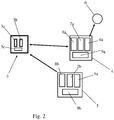
- the figures show an alarm system suitable for implementing the method according to the present invention, for identifying, recognizing, and disarming an alarm central 3, for monitoring a protected space 1 comprising at least one access opening closed by a door 2.
- the central unit 3 or, if appropriate, the or each assembly is provided to automatically enable, following detection by the detection sensor or sensors 5a, 5b, on the one hand, to the armed state of the central unit 3, the activation control of the proximity transmitter / receiver 4a, 4b concerned, as defined in step b / i / of the method according to the invention (see p. 6.1, 15-25), and on the other hand, in the disarmed state of the central unit 3, the maintenance, as defined in step b / v / of the method according to the invention (see FIG. 6, 1, 15-25), the or each proximity transmitter / receiver 4a, 4b in the standby state by acting directly or indirectly on this or these latter.
- the or each set comprises timing means allowing the automatic control, after the predetermined duration t0, of the deactivation as defined in step b / iv / of the method according to the invention (cf. pp. 6, 1, 15-25).
- the main communication module 3b of the alarm central unit 3 can be provided to be able to communicate wirelessly by radio frequency, possibly by wire, with the secondary communication module or modules 8a, 8b, 8c.
- the or each secondary communication module 8a, 8b, 8c can be provided to be able to communicate wirelessly by radio frequency, where appropriate wired, with the main communication module 3b.
- the detection sensor (s) 5a, 5b of the or each set may be functionally connected to the one or one of the secondary central processing units 7a, 7b, 7c of the same corresponding set.
- this may consist in step b / iv / of controlling the deactivation of the transmitter / receiver 4a, 4b since the or one of the central processing units 7a, 7c of the same set.
- the central unit 3 may include a memory containing the list of valid identifiers relating to the portable media 6.
- the method may consist of control, thanks to the system, in response to the arming of the central unit 3 in the armed state, prior to step a /, the activation of the transmitter / receiver 4a, 4b of the or each set, to put automatically or each transmitter / receiver 4a, 4b in the activated state for a predetermined period so as to detect the possible presence of a portable support 6 allowed in the protected space 1, then to control, after a predetermined period, the deactivation of the or each transmitter / receiver 4a, 4b activated so as to put it (s) in standby state, and in that it consists in the case of such presence to temporarily inhibit the portable medium 6 in the list i valid identifiers stored in the central unit 3 until it is next disarmed.
- the deactivation command, in this preliminary step following the arming, automatic or manual, of the alarm unit 3 can be carried out from
- the method may consist, in the case where the signaling message is transmitted on at least two transmission channels 10 used successively in a predetermined order by the or each proximity transmitter / receiver 4a, 4b and where no communication is required. has been established in the first transmission channel 10a used, to successively use the other transmission channel or channels 10b, 10c until communication is established or until the last transmission channel 10c has been used. by the or each proximity transmitter / receiver 4a, 4b ( figure 4c ).
- the present invention can thus allow the or each proximity transmitter / receiver 4a, 4b to continue its activation duration t0 by reproducing it with each successive use, if any, of a other transmission channel ( figure 4c ).
- the or each transmitter / receiver 4a proximity, 4b concerned may be adapted to prioritize the order in which it will listen to the transmission channels 10a, 10b, 10c to reduce the probability of interference may introduce a delay in establishing communication between the latter and the media concerned 6 laptops.
- the or each portable support 6 can transmit permanently, according to a predetermined rhythm, a message of signage indicating his presence.
- the rate may be set so that the cycle time t1 is preferably greater than 0.7 seconds and less than 5 seconds. Indeed tests conducted by the present applicant have shown that for a duration of the cycle t1 less than or equal to 0.7 seconds, the rate of signaling becomes so fast that the resulting power consumption exceeds 500 mAh per year of operation, which can exceed the possibilities of the power source of the or each portable support 6.
- the response time of the system becomes very long, knowing that the total duration of activation of the or each proximity transmitter / receiver 4a, 4b in the case of a plurality of transmission channels three transmission channels is a multiple of t0, for example in the case of three channels is equal at three times the predetermined duration t0 ( figure 4c ).
- the time during which a person is admitted into the protected zone before the alarm is triggered is set at about 30 seconds, which is supposed to be enough to disable the system. alarm, for example by entering a code or presenting a badge such as a portable support 6.
- the duration t1 of the cycle can be between 1.5 and 3 seconds, so as to preferably provide a range of values of t1 to obtain the best compromise responsiveness / energy saving.
- the predetermined duration t0 may be, for example, preferably between 1.7 and 4.5 seconds, more preferably equal to about 1.7 seconds. Note that with an activation time t0 much greater than the duration t1 of the emission cycle we can obtain a probability equal to 100% for the emission-reception coincidence (P-zones dotted on the Figures 4a, 4b, 4c ), even if there is a temporal phase shift ( figure 4b ) between the or each proximity transmitter / receiver 4a, 4b and the portable support 6 concerned in the field of the latter.
- the predetermined duration t0 and the duration t1 of the cycle can be stored in a memory that can be understood by the system, for example at the level of the alarm unit 3 or the or each set, said memory then being able to be connected to the unit treatment plant or to one of the secondary treatment units, the latter being then adapted to process these values of duration t0 and t1 predetermined and stored.
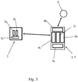
- the or each set may consist of a detector / reader 4, 5 autonomous that can integrate the secondary processing unit 7c, the secondary communication module 8c, the proximity transmitter / receiver 4b, the detection sensor or sensors 5b and the secondary energy source 9c.
- the secondary central processing unit 7c of the or each assembly may be provided to be able to control, following detection by the corresponding detection sensor (s) 5b (s), the activation of the transmitter / receiver of proximity 4b as defined in step b / i / of the method in its first embodiment.
- the main central processing unit 3a of the central unit 3 can be adapted to be able to send, via the main communication module 3b and the corresponding secondary communication module 8c, to the secondary central processing unit 7c of the central processing unit 3c. or each set of information signal representative of the state of arming of the central 3 as defined in the method in its first embodiment.
- the or each set can thus form an autonomous entity, namely the detector / reader 4, 5.
- the secondary central processing unit 7c of the detector / reader 4, 5 of the or each set can be connected functionally to the other components of the detector / reader 4, 5 which it is then common, namely, in particular, the proximity transmitter / receiver 4b, the secondary communication module 8c, (x) sensor (s) detection 5a and the secondary energy source 9a allowing their autonomous power supply.
- the detector / reader 4, 5 may comprise a housing enclosing an electronic card, if necessary a plurality of electronic cards connected together, integrating the secondary central processing unit 7c, the secondary communication module 8c, the transceiver 4b, the detection sensor (s) 5b and the secondary energy source 9c.
- the reader 4 and the detector 5 can be integrated in the same housing.
- the or each set may consist, on the one hand, of an autonomous reader 4 which can integrate the proximity transmitter / receiver 4a, one of the two secondary central processing units 7a, one of the two secondary communication modules 8a, the latter can be bidirectional, and one of the two sources of secondary energy 9a and, on the other hand, an autonomous detector 5 which can integrate the other communication module 8b, the detection sensor or sensors 5a, the other energy source 9b and the other secondary central processing unit 7b adapted to be able to send to the central 3, that is to say via the corresponding secondary communication module 8b and the main communication module 3b, the signal representative of the detection as defined in step a / of the method in his second th embodiment.
- an autonomous reader 4 which can integrate the proximity transmitter / receiver 4a, one of the two secondary central processing units 7a, one of the two secondary communication modules 8a, the latter can be bidirectional, and one of the two sources of secondary energy 9a and, on the other hand, an autonomous detector 5 which can integrate the other communication module 8b, the detection sensor or sensors 5a
- the main central processing unit 3a of the central unit 3 can be provided to be able to control, via the main communication module 3b and the corresponding secondary communication module 8a, the activation of the proximity transmitter / receiver 4a. as defined in step b / i / of the method in its second embodiment.
- the or each set can thus form two autonomous entities, namely the reader 4 and the detector 5 and that the or each set can comprise a transmitter 4a / proximity receiver integrated in the reader 4, two secondary central processing units 7a, 7b, one of which 7a is integrated in the reader 4 and the other 7b in the detector 5, at least one integrated detection sensor 5a in the detector 5, two secondary energy sources 9a, 9b, one of which 9a is integrated in the reader 4 and the other 9b in the detector 5, and two secondary communication modules 8a, 8b, one of which 8a is integrated in the reader 4 and the other 8b in the detector 5.
- the secondary central processing unit 7a of the reader 4 of the or each assembly can be functionally connected to the other constituent elements of the reader 4, namely, in particular, the transmitter / receiver 4a, the secondary communication module 8a and the secondary energy source 9a allowing their autonomous power supply and that the secondary central processing unit 7b of the detector 5 of the or each assembly can be functionally connected to the other constituent elements the detector, namely, in particular, the detection sensor (s) 5a, the secondary communication module 8b and the secondary energy source 9b allowing their autonomous power supply.
- the reader 4 may comprise a box enclosing an electronic card, if necessary a plurality of electronic cards connected together, integrating the transmitter / receiver 4a, one of the two secondary central processing units 7a, one of the two secondary communication modules 8a and one of the two energy sources 9a and the detector 5 may comprise another box enclosing an electronic card, if necessary a plurality of electronic boards connected together, integrating the other communication module 8b, the detection sensor or sensors 5a, the other secondary processing unit 7b and the other secondary energy source 9b.
- the step b / v / of the method according to the invention from the or each set provided so that the or each detection sensor 5a, 5b can be activated or put in a standby state, may consist in setting directly or indirectly the proximity transmitter / receiver 4a, 4b in standby state either by acting directly on it or by acting directly on the or each detection sensor 5a, 5b concerned to put it or these in a state of Eve.
- the proximity transmitter / receiver 4a, 4b concerned can no longer be set to the activation state since this activation state is controlled according to the invention as soon as the detection by the or each sensor concerned is effective.
- the or each activation control circuit 7a, 7b can be adapted to send, on a predetermined duration through the timer circuit (s), an activation order to the reader 4 of the or each set as defined in the method as such.
- the present invention can provide that the reader 4 can be integrated in the detector 5, without disturbing or preventing the operation of the detector.
- the integration of the detector in the reader may pose a problem of operation of the detector that may malfunction or may not be able to ensure detection correctly.
Landscapes
- Engineering & Computer Science (AREA)
- Computer Security & Cryptography (AREA)
- Business, Economics & Management (AREA)
- Emergency Management (AREA)
- Physics & Mathematics (AREA)
- General Physics & Mathematics (AREA)
- Computer Networks & Wireless Communication (AREA)
- Signal Processing (AREA)
- Burglar Alarm Systems (AREA)
- Alarm Systems (AREA)
- Arrangements For Transmission Of Measured Signals (AREA)
Priority Applications (1)
| Application Number | Priority Date | Filing Date | Title |
|---|---|---|---|
| PL15306710T PL3016078T3 (pl) | 2014-10-29 | 2015-10-26 | Sposób automatycznego wykrywania, rozpoznawania i rozbrajania centrali alarmowej oraz układ alarmowy odpowiedni do jego realizowania |
Applications Claiming Priority (1)
| Application Number | Priority Date | Filing Date | Title |
|---|---|---|---|
| FR1460378A FR3028083B1 (fr) | 2014-10-29 | 2014-10-29 | Procede de detection, de reconnaissance, et de desarmement automatique d'une centrale d'alarme, et systeme d'alarme convenant a sa mise œuvre |
Publications (2)
| Publication Number | Publication Date |
|---|---|
| EP3016078A1 EP3016078A1 (fr) | 2016-05-04 |
| EP3016078B1 true EP3016078B1 (fr) | 2017-08-16 |
Family
ID=52021344
Family Applications (1)
| Application Number | Title | Priority Date | Filing Date |
|---|---|---|---|
| EP15306710.3A Active EP3016078B1 (fr) | 2014-10-29 | 2015-10-26 | Procédé de détection, de reconnaissance, et de désarmement automatique d'une centrale d'alarme, et système d'alarme convenant à sa mise en oeuvre |
Country Status (7)
| Country | Link |
|---|---|
| US (1) | US9728072B2 (pl) |
| EP (1) | EP3016078B1 (pl) |
| CA (1) | CA2910450A1 (pl) |
| DK (1) | DK3016078T3 (pl) |
| ES (1) | ES2647633T3 (pl) |
| FR (1) | FR3028083B1 (pl) |
| PL (1) | PL3016078T3 (pl) |
Families Citing this family (13)
| Publication number | Priority date | Publication date | Assignee | Title |
|---|---|---|---|---|
| US8395477B2 (en) * | 2009-10-29 | 2013-03-12 | Time Warner Cable Inc. | Geographic based remote control |
| US10057715B1 (en) * | 2017-03-29 | 2018-08-21 | Honeywell International Inc. | Systems and methods for selecting an optimal device in a home security or automation system for presenting a notification or alert |
| EP3393149B1 (en) * | 2017-04-18 | 2023-03-22 | Valmet Automation Oy | Method and arrangement for activating wireless connection |
| US10347116B2 (en) * | 2017-05-16 | 2019-07-09 | Tyco Fire & Security Gmbh | System and method for automatically disarming an intrusion detection system |
| US10672256B2 (en) * | 2017-05-30 | 2020-06-02 | Tyco Fire & Security Gmbh | System and method for automatically disarming an intrusion detection system |
| US10861270B2 (en) | 2018-02-01 | 2020-12-08 | Halo Maritime Defense Systems, Inc. | Presence-based automatic gate operation for marine barriers and gate systems |
| US10140839B1 (en) * | 2018-03-12 | 2018-11-27 | Tyco Safety Products Canada Ltd. | Alarm system communicator for forwarding alarm system event data |
| EP3561789B1 (en) * | 2018-04-24 | 2026-03-11 | Carrier Corporation | Improved home security system with automatic authorization functionality |
| KR102674973B1 (ko) | 2018-12-07 | 2024-06-14 | 삼성전자주식회사 | 사용자의 위치를 감지하기 위한 전자 장치 및 그에 관한 방법 |
| ES2815749B2 (es) * | 2019-09-30 | 2023-02-23 | Verisure Sarl | Sistema de monitorizacion de seguridad |
| ES2815723B2 (es) * | 2019-09-30 | 2022-10-11 | Verisure Sarl | Sistema monitorizacion de seguridad |
| ES2744027A1 (es) * | 2019-12-23 | 2020-02-21 | Savinska Constantino Martin | Sistema para la disuasion del robo de bolsos o complementos. |
| GB202206415D0 (en) * | 2022-05-03 | 2022-06-15 | Essence Security International Esi Ltd | IoT security device |
Family Cites Families (7)
| Publication number | Priority date | Publication date | Assignee | Title |
|---|---|---|---|---|
| US4647914A (en) * | 1984-07-20 | 1987-03-03 | Mitsubishi Electric America, Inc. | Security apparatus and system |
| US5594428A (en) * | 1994-07-22 | 1997-01-14 | Digital Security Controls Ltd. | Combination security unit |
| US7696873B2 (en) * | 2006-09-12 | 2010-04-13 | Tyco Safety Products Canada Ltd. | Method and apparatus for automatically disarming a security system |
| JP2008149865A (ja) * | 2006-12-15 | 2008-07-03 | Denso Corp | セキュリティー装置 |
| US8487747B2 (en) * | 2008-05-23 | 2013-07-16 | At&T Intellectual Property I, L.P. | Method and system for controlling the traffic flow through an RFID directional portal |
| US8653982B2 (en) * | 2009-07-21 | 2014-02-18 | Openings | Door monitoring system |
| FR2949268B1 (fr) | 2009-08-20 | 2012-09-28 | Radio Systemes Ingenierie Video Technologies | Dispositif de detection d'entree et de reconnaissance de badges transpondeurs, systeme de surveillance le comprenant et procede de surveillance mis en oeuvre par ledit systeme |
-
2014
- 2014-10-29 FR FR1460378A patent/FR3028083B1/fr active Active
-
2015
- 2015-10-26 ES ES15306710.3T patent/ES2647633T3/es active Active
- 2015-10-26 PL PL15306710T patent/PL3016078T3/pl unknown
- 2015-10-26 DK DK15306710.3T patent/DK3016078T3/da active
- 2015-10-26 EP EP15306710.3A patent/EP3016078B1/fr active Active
- 2015-10-27 US US14/923,805 patent/US9728072B2/en active Active
- 2015-10-28 CA CA2910450A patent/CA2910450A1/fr not_active Abandoned
Non-Patent Citations (1)
| Title |
|---|
| None * |
Also Published As
| Publication number | Publication date |
|---|---|
| EP3016078A1 (fr) | 2016-05-04 |
| CA2910450A1 (fr) | 2016-04-29 |
| US9728072B2 (en) | 2017-08-08 |
| US20160133120A1 (en) | 2016-05-12 |
| ES2647633T3 (es) | 2017-12-22 |
| FR3028083B1 (fr) | 2016-12-30 |
| PL3016078T3 (pl) | 2018-03-30 |
| FR3028083A1 (fr) | 2016-05-06 |
| DK3016078T3 (da) | 2017-11-27 |
Similar Documents
| Publication | Publication Date | Title |
|---|---|---|
| EP3016078A1 (fr) | Procédé de détection, de reconnaissance, et de désarmement automatique d'une centrale d'alarme, et système d'alarme convenant à sa mise en oeuvre | |
| AU2022202582B2 (en) | Doorbell call center | |
| EP2287812B1 (fr) | Dispositif de détection d'entrée et de reconnaissance de badges transpondeurs, système de surveillance le comprenant et procédé de surveillance mis en oeuvre par ledit système | |
| EP2041735B1 (fr) | Procede de communication par radiofrequences dans une installation domotique | |
| EP3472811B1 (fr) | Capteur d'alarme, systeme comprenant un tel capteur | |
| WO2020043877A1 (fr) | Procede de localisation de donnees, systeme de controle, dispositif emetteur | |
| FR3040817A1 (fr) | Procedes de desarmement automatique et d'utilisation d'un systeme d'alarme anti-intrusion, et systeme d'alarme associe | |
| FR2537308A1 (fr) | Procede et dispositif de transmission d'informations | |
| EP0210889B1 (fr) | Centrale modulaire de surveillance et d'alarme de haute sécurité, et procédé de fonctionnement correspondant | |
| FR3085241A1 (fr) | Systeme de surveillance de securite et noeud pour un tel systeme | |
| FR2814267A1 (fr) | Procede de mise en oeuvre et dispositif de surveillance destine a prevenir lors d'une intrusion dans la zone qu'il surveille | |
| EP1499154B1 (fr) | Procédé de communication radiofréquence bidirectionnel entre plusieurs modules d'un système | |
| WO2002011096A1 (fr) | Procede et dispositif pour la protection en continu contre les intrusions dans des locaux eventuellement habites | |
| EP3314592B1 (fr) | Dispositif domotique, procédé de contrôle d'un dispositif domotique et programme d'ordinateur | |
| CA3124177C (fr) | Dispositif et procede de surveillance d'une situation au sein d'un volume | |
| FR3085245A1 (fr) | Systeme de surveillance de securite, noeud et unite centrale pour un tel systeme | |
| RU143877U1 (ru) | Автономное портативное радиоканальное устройство обнаружения и связи | |
| EP3956874B1 (fr) | Systeme de gestion d'une pluralite d'espaces individuels sous alarme | |
| FR2691274A1 (fr) | Capteur, centre de surveillance et réseau domotique de surveillance. | |
| EP3038396A1 (fr) | Balise a multiples interfaces de communication a desactivation/reactivation securisees | |
| CA2614211A1 (fr) | Dispositif de securisation d'un espace clos par identification |
Legal Events
| Date | Code | Title | Description |
|---|---|---|---|
| PUAI | Public reference made under article 153(3) epc to a published international application that has entered the european phase |
Free format text: ORIGINAL CODE: 0009012 |
|
| AK | Designated contracting states |
Kind code of ref document: A1 Designated state(s): AL AT BE BG CH CY CZ DE DK EE ES FI FR GB GR HR HU IE IS IT LI LT LU LV MC MK MT NL NO PL PT RO RS SE SI SK SM TR |
|
| AX | Request for extension of the european patent |
Extension state: BA ME |
|
| 17P | Request for examination filed |
Effective date: 20161104 |
|
| RBV | Designated contracting states (corrected) |
Designated state(s): AL AT BE BG CH CY CZ DE DK EE ES FI FR GB GR HR HU IE IS IT LI LT LU LV MC MK MT NL NO PL PT RO RS SE SI SK SM TR |
|
| GRAP | Despatch of communication of intention to grant a patent |
Free format text: ORIGINAL CODE: EPIDOSNIGR1 |
|
| INTG | Intention to grant announced |
Effective date: 20170119 |
|
| GRAS | Grant fee paid |
Free format text: ORIGINAL CODE: EPIDOSNIGR3 |
|
| GRAJ | Information related to disapproval of communication of intention to grant by the applicant or resumption of examination proceedings by the epo deleted |
Free format text: ORIGINAL CODE: EPIDOSDIGR1 |
|
| GRAL | Information related to payment of fee for publishing/printing deleted |
Free format text: ORIGINAL CODE: EPIDOSDIGR3 |
|
| INTC | Intention to grant announced (deleted) | ||
| GRAJ | Information related to disapproval of communication of intention to grant by the applicant or resumption of examination proceedings by the epo deleted |
Free format text: ORIGINAL CODE: EPIDOSDIGR1 |
|
| GRAP | Despatch of communication of intention to grant a patent |
Free format text: ORIGINAL CODE: EPIDOSNIGR1 |
|
| GRAR | Information related to intention to grant a patent recorded |
Free format text: ORIGINAL CODE: EPIDOSNIGR71 |
|
| GRAA | (expected) grant |
Free format text: ORIGINAL CODE: 0009210 |
|
| AK | Designated contracting states |
Kind code of ref document: B1 Designated state(s): AL AT BE BG CH CY CZ DE DK EE ES FI FR GB GR HR HU IE IS IT LI LT LU LV MC MK MT NL NO PL PT RO RS SE SI SK SM TR |
|
| INTG | Intention to grant announced |
Effective date: 20170707 |
|
| REG | Reference to a national code |
Ref country code: GB Ref legal event code: FG4D Free format text: NOT ENGLISH |
|
| REG | Reference to a national code |
Ref country code: CH Ref legal event code: EP |
|
| REG | Reference to a national code |
Ref country code: IE Ref legal event code: FG4D Free format text: LANGUAGE OF EP DOCUMENT: FRENCH |
|
| REG | Reference to a national code |
Ref country code: AT Ref legal event code: REF Ref document number: 919765 Country of ref document: AT Kind code of ref document: T Effective date: 20170915 |
|
| REG | Reference to a national code |
Ref country code: DE Ref legal event code: R096 Ref document number: 602015004168 Country of ref document: DE |
|
| REG | Reference to a national code |
Ref country code: FR Ref legal event code: PLFP Year of fee payment: 3 |
|
| REG | Reference to a national code |
Ref country code: DK Ref legal event code: T3 Effective date: 20171123 |
|
| REG | Reference to a national code |
Ref country code: SE Ref legal event code: TRGR |
|
| REG | Reference to a national code |
Ref country code: NL Ref legal event code: FP |
|
| REG | Reference to a national code |
Ref country code: CH Ref legal event code: NV Representative=s name: OK PAT AG PATENTE MARKEN LIZENZEN, CH |
|
| REG | Reference to a national code |
Ref country code: ES Ref legal event code: FG2A Ref document number: 2647633 Country of ref document: ES Kind code of ref document: T3 Effective date: 20171222 |
|
| REG | Reference to a national code |
Ref country code: LT Ref legal event code: MG4D |
|
| REG | Reference to a national code |
Ref country code: AT Ref legal event code: MK05 Ref document number: 919765 Country of ref document: AT Kind code of ref document: T Effective date: 20170816 |
|
| PG25 | Lapsed in a contracting state [announced via postgrant information from national office to epo] |
Ref country code: LT Free format text: LAPSE BECAUSE OF FAILURE TO SUBMIT A TRANSLATION OF THE DESCRIPTION OR TO PAY THE FEE WITHIN THE PRESCRIBED TIME-LIMIT Effective date: 20170816 Ref country code: AT Free format text: LAPSE BECAUSE OF FAILURE TO SUBMIT A TRANSLATION OF THE DESCRIPTION OR TO PAY THE FEE WITHIN THE PRESCRIBED TIME-LIMIT Effective date: 20170816 Ref country code: NO Free format text: LAPSE BECAUSE OF FAILURE TO SUBMIT A TRANSLATION OF THE DESCRIPTION OR TO PAY THE FEE WITHIN THE PRESCRIBED TIME-LIMIT Effective date: 20171116 Ref country code: FI Free format text: LAPSE BECAUSE OF FAILURE TO SUBMIT A TRANSLATION OF THE DESCRIPTION OR TO PAY THE FEE WITHIN THE PRESCRIBED TIME-LIMIT Effective date: 20170816 |
|
| PG25 | Lapsed in a contracting state [announced via postgrant information from national office to epo] |
Ref country code: BG Free format text: LAPSE BECAUSE OF FAILURE TO SUBMIT A TRANSLATION OF THE DESCRIPTION OR TO PAY THE FEE WITHIN THE PRESCRIBED TIME-LIMIT Effective date: 20171116 Ref country code: LV Free format text: LAPSE BECAUSE OF FAILURE TO SUBMIT A TRANSLATION OF THE DESCRIPTION OR TO PAY THE FEE WITHIN THE PRESCRIBED TIME-LIMIT Effective date: 20170816 Ref country code: IS Free format text: LAPSE BECAUSE OF FAILURE TO SUBMIT A TRANSLATION OF THE DESCRIPTION OR TO PAY THE FEE WITHIN THE PRESCRIBED TIME-LIMIT Effective date: 20171216 Ref country code: GR Free format text: LAPSE BECAUSE OF FAILURE TO SUBMIT A TRANSLATION OF THE DESCRIPTION OR TO PAY THE FEE WITHIN THE PRESCRIBED TIME-LIMIT Effective date: 20171117 Ref country code: RS Free format text: LAPSE BECAUSE OF FAILURE TO SUBMIT A TRANSLATION OF THE DESCRIPTION OR TO PAY THE FEE WITHIN THE PRESCRIBED TIME-LIMIT Effective date: 20170816 |
|
| PG25 | Lapsed in a contracting state [announced via postgrant information from national office to epo] |
Ref country code: CZ Free format text: LAPSE BECAUSE OF FAILURE TO SUBMIT A TRANSLATION OF THE DESCRIPTION OR TO PAY THE FEE WITHIN THE PRESCRIBED TIME-LIMIT Effective date: 20170816 Ref country code: RO Free format text: LAPSE BECAUSE OF FAILURE TO SUBMIT A TRANSLATION OF THE DESCRIPTION OR TO PAY THE FEE WITHIN THE PRESCRIBED TIME-LIMIT Effective date: 20170816 |
|
| REG | Reference to a national code |
Ref country code: DE Ref legal event code: R097 Ref document number: 602015004168 Country of ref document: DE |
|
| PG25 | Lapsed in a contracting state [announced via postgrant information from national office to epo] |
Ref country code: EE Free format text: LAPSE BECAUSE OF FAILURE TO SUBMIT A TRANSLATION OF THE DESCRIPTION OR TO PAY THE FEE WITHIN THE PRESCRIBED TIME-LIMIT Effective date: 20170816 Ref country code: SK Free format text: LAPSE BECAUSE OF FAILURE TO SUBMIT A TRANSLATION OF THE DESCRIPTION OR TO PAY THE FEE WITHIN THE PRESCRIBED TIME-LIMIT Effective date: 20170816 Ref country code: MC Free format text: LAPSE BECAUSE OF FAILURE TO SUBMIT A TRANSLATION OF THE DESCRIPTION OR TO PAY THE FEE WITHIN THE PRESCRIBED TIME-LIMIT Effective date: 20170816 Ref country code: SM Free format text: LAPSE BECAUSE OF FAILURE TO SUBMIT A TRANSLATION OF THE DESCRIPTION OR TO PAY THE FEE WITHIN THE PRESCRIBED TIME-LIMIT Effective date: 20170816 |
|
| PLBE | No opposition filed within time limit |
Free format text: ORIGINAL CODE: 0009261 |
|
| STAA | Information on the status of an ep patent application or granted ep patent |
Free format text: STATUS: NO OPPOSITION FILED WITHIN TIME LIMIT |
|
| 26N | No opposition filed |
Effective date: 20180517 |
|
| REG | Reference to a national code |
Ref country code: IE Ref legal event code: MM4A |
|
| PG25 | Lapsed in a contracting state [announced via postgrant information from national office to epo] |
Ref country code: SI Free format text: LAPSE BECAUSE OF FAILURE TO SUBMIT A TRANSLATION OF THE DESCRIPTION OR TO PAY THE FEE WITHIN THE PRESCRIBED TIME-LIMIT Effective date: 20170816 |
|
| PG25 | Lapsed in a contracting state [announced via postgrant information from national office to epo] |
Ref country code: MT Free format text: LAPSE BECAUSE OF FAILURE TO SUBMIT A TRANSLATION OF THE DESCRIPTION OR TO PAY THE FEE WITHIN THE PRESCRIBED TIME-LIMIT Effective date: 20170816 |
|
| PG25 | Lapsed in a contracting state [announced via postgrant information from national office to epo] |
Ref country code: IE Free format text: LAPSE BECAUSE OF NON-PAYMENT OF DUE FEES Effective date: 20171026 |
|
| REG | Reference to a national code |
Ref country code: FR Ref legal event code: PLFP Year of fee payment: 4 |
|
| PG25 | Lapsed in a contracting state [announced via postgrant information from national office to epo] |
Ref country code: HU Free format text: LAPSE BECAUSE OF FAILURE TO SUBMIT A TRANSLATION OF THE DESCRIPTION OR TO PAY THE FEE WITHIN THE PRESCRIBED TIME-LIMIT; INVALID AB INITIO Effective date: 20151026 |
|
| PG25 | Lapsed in a contracting state [announced via postgrant information from national office to epo] |
Ref country code: CY Free format text: LAPSE BECAUSE OF FAILURE TO SUBMIT A TRANSLATION OF THE DESCRIPTION OR TO PAY THE FEE WITHIN THE PRESCRIBED TIME-LIMIT Effective date: 20170816 |
|
| PG25 | Lapsed in a contracting state [announced via postgrant information from national office to epo] |
Ref country code: MK Free format text: LAPSE BECAUSE OF FAILURE TO SUBMIT A TRANSLATION OF THE DESCRIPTION OR TO PAY THE FEE WITHIN THE PRESCRIBED TIME-LIMIT Effective date: 20170816 |
|
| PGFP | Annual fee paid to national office [announced via postgrant information from national office to epo] |
Ref country code: LU Payment date: 20191025 Year of fee payment: 5 |
|
| PGFP | Annual fee paid to national office [announced via postgrant information from national office to epo] |
Ref country code: DE Payment date: 20191129 Year of fee payment: 5 Ref country code: NL Payment date: 20191025 Year of fee payment: 5 |
|
| PGFP | Annual fee paid to national office [announced via postgrant information from national office to epo] |
Ref country code: BE Payment date: 20191025 Year of fee payment: 5 Ref country code: IT Payment date: 20191024 Year of fee payment: 5 Ref country code: DK Payment date: 20191024 Year of fee payment: 5 |
|
| PGFP | Annual fee paid to national office [announced via postgrant information from national office to epo] |
Ref country code: TR Payment date: 20191015 Year of fee payment: 5 Ref country code: CH Payment date: 20191025 Year of fee payment: 5 |
|
| PGFP | Annual fee paid to national office [announced via postgrant information from national office to epo] |
Ref country code: GB Payment date: 20191029 Year of fee payment: 5 |
|
| PG25 | Lapsed in a contracting state [announced via postgrant information from national office to epo] |
Ref country code: PT Free format text: LAPSE BECAUSE OF FAILURE TO SUBMIT A TRANSLATION OF THE DESCRIPTION OR TO PAY THE FEE WITHIN THE PRESCRIBED TIME-LIMIT Effective date: 20170816 |
|
| PG25 | Lapsed in a contracting state [announced via postgrant information from national office to epo] |
Ref country code: HR Free format text: LAPSE BECAUSE OF FAILURE TO SUBMIT A TRANSLATION OF THE DESCRIPTION OR TO PAY THE FEE WITHIN THE PRESCRIBED TIME-LIMIT Effective date: 20170816 |
|
| PG25 | Lapsed in a contracting state [announced via postgrant information from national office to epo] |
Ref country code: AL Free format text: LAPSE BECAUSE OF FAILURE TO SUBMIT A TRANSLATION OF THE DESCRIPTION OR TO PAY THE FEE WITHIN THE PRESCRIBED TIME-LIMIT Effective date: 20170816 |
|
| PGFP | Annual fee paid to national office [announced via postgrant information from national office to epo] |
Ref country code: PL Payment date: 20191022 Year of fee payment: 5 |
|
| REG | Reference to a national code |
Ref country code: CH Ref legal event code: PFUS Owner name: RADIO SYSTEMES INGENIERIE VIDEO TECHNOLOGIES S, FR Free format text: FORMER OWNER: RADIO SYSTEMES INGENIERIE VIDEO TECHNOLOGIES SOCIETE PAR ACTIONS SIMPLIFIEE, FR |
|
| REG | Reference to a national code |
Ref country code: DE Ref legal event code: R119 Ref document number: 602015004168 Country of ref document: DE |
|
| REG | Reference to a national code |
Ref country code: DK Ref legal event code: EBP Effective date: 20201031 |
|
| REG | Reference to a national code |
Ref country code: CH Ref legal event code: PL |
|
| REG | Reference to a national code |
Ref country code: NL Ref legal event code: MM Effective date: 20201101 |
|
| GBPC | Gb: european patent ceased through non-payment of renewal fee |
Effective date: 20201026 |
|
| PG25 | Lapsed in a contracting state [announced via postgrant information from national office to epo] |
Ref country code: LU Free format text: LAPSE BECAUSE OF NON-PAYMENT OF DUE FEES Effective date: 20201026 |
|
| REG | Reference to a national code |
Ref country code: BE Ref legal event code: MM Effective date: 20201031 |
|
| PG25 | Lapsed in a contracting state [announced via postgrant information from national office to epo] |
Ref country code: NL Free format text: LAPSE BECAUSE OF NON-PAYMENT OF DUE FEES Effective date: 20201101 Ref country code: DE Free format text: LAPSE BECAUSE OF NON-PAYMENT OF DUE FEES Effective date: 20210501 |
|
| PG25 | Lapsed in a contracting state [announced via postgrant information from national office to epo] |
Ref country code: BE Free format text: LAPSE BECAUSE OF NON-PAYMENT OF DUE FEES Effective date: 20201031 Ref country code: CH Free format text: LAPSE BECAUSE OF NON-PAYMENT OF DUE FEES Effective date: 20201031 Ref country code: LI Free format text: LAPSE BECAUSE OF NON-PAYMENT OF DUE FEES Effective date: 20201031 Ref country code: GB Free format text: LAPSE BECAUSE OF NON-PAYMENT OF DUE FEES Effective date: 20201026 |
|
| PG25 | Lapsed in a contracting state [announced via postgrant information from national office to epo] |
Ref country code: IT Free format text: LAPSE BECAUSE OF NON-PAYMENT OF DUE FEES Effective date: 20201026 |
|
| PG25 | Lapsed in a contracting state [announced via postgrant information from national office to epo] |
Ref country code: DK Free format text: LAPSE BECAUSE OF NON-PAYMENT OF DUE FEES Effective date: 20201031 |
|
| PG25 | Lapsed in a contracting state [announced via postgrant information from national office to epo] |
Ref country code: TR Free format text: LAPSE BECAUSE OF NON-PAYMENT OF DUE FEES Effective date: 20201026 |
|
| PG25 | Lapsed in a contracting state [announced via postgrant information from national office to epo] |
Ref country code: PL Free format text: LAPSE BECAUSE OF NON-PAYMENT OF DUE FEES Effective date: 20201026 |
|
| P01 | Opt-out of the competence of the unified patent court (upc) registered |
Effective date: 20230601 |
|
| PGFP | Annual fee paid to national office [announced via postgrant information from national office to epo] |
Ref country code: FR Payment date: 20251027 Year of fee payment: 11 |
|
| PGFP | Annual fee paid to national office [announced via postgrant information from national office to epo] |
Ref country code: SE Payment date: 20251024 Year of fee payment: 11 |
|
| PGFP | Annual fee paid to national office [announced via postgrant information from national office to epo] |
Ref country code: ES Payment date: 20251118 Year of fee payment: 11 |