EP3015841A2 - Vehicle loading condition detection system and method - Google Patents
Vehicle loading condition detection system and method Download PDFInfo
- Publication number
- EP3015841A2 EP3015841A2 EP15190494.3A EP15190494A EP3015841A2 EP 3015841 A2 EP3015841 A2 EP 3015841A2 EP 15190494 A EP15190494 A EP 15190494A EP 3015841 A2 EP3015841 A2 EP 3015841A2
- Authority
- EP
- European Patent Office
- Prior art keywords
- tire
- chassis
- vehicle
- load
- operative
- Prior art date
- Legal status (The legal status is an assumption and is not a legal conclusion. Google has not performed a legal analysis and makes no representation as to the accuracy of the status listed.)
- Ceased
Links
Images


Classifications
-
- G—PHYSICS
- G01—MEASURING; TESTING
- G01M—TESTING STATIC OR DYNAMIC BALANCE OF MACHINES OR STRUCTURES; TESTING OF STRUCTURES OR APPARATUS, NOT OTHERWISE PROVIDED FOR
- G01M17/00—Testing of vehicles
- G01M17/007—Wheeled or endless-tracked vehicles
- G01M17/02—Tyres
-
- B—PERFORMING OPERATIONS; TRANSPORTING
- B60—VEHICLES IN GENERAL
- B60C—VEHICLE TYRES; TYRE INFLATION; TYRE CHANGING; CONNECTING VALVES TO INFLATABLE ELASTIC BODIES IN GENERAL; DEVICES OR ARRANGEMENTS RELATED TO TYRES
- B60C23/00—Devices for measuring, signalling, controlling, or distributing tyre pressure or temperature, specially adapted for mounting on vehicles; Arrangement of tyre inflating devices on vehicles, e.g. of pumps or of tanks; Tyre cooling arrangements
- B60C23/02—Signalling devices actuated by tyre pressure
- B60C23/04—Signalling devices actuated by tyre pressure mounted on the wheel or tyre
- B60C23/0408—Signalling devices actuated by tyre pressure mounted on the wheel or tyre transmitting the signals by non-mechanical means from the wheel or tyre to a vehicle body mounted receiver
-
- G—PHYSICS
- G01—MEASURING; TESTING
- G01L—MEASURING FORCE, STRESS, TORQUE, WORK, MECHANICAL POWER, MECHANICAL EFFICIENCY, OR FLUID PRESSURE
- G01L5/00—Apparatus for, or methods of, measuring force, work, mechanical power, or torque, specially adapted for specific purposes
-
- G—PHYSICS
- G01—MEASURING; TESTING
- G01M—TESTING STATIC OR DYNAMIC BALANCE OF MACHINES OR STRUCTURES; TESTING OF STRUCTURES OR APPARATUS, NOT OTHERWISE PROVIDED FOR
- G01M17/00—Testing of vehicles
- G01M17/007—Wheeled or endless-tracked vehicles
Definitions
- the invention relates generally to systems for indirectly estimating a vehicle's loading condition based upon analytic assessment of vehicle operating parameters.
- the loading condition of a vehicle may be measured by various techniques and methodologies.
- vehicle-mounted tires may be equipped with strain sensors that detect and measure the deflection of each tire from tire loading.
- systems such as stability/brake/ traction control systems may be adjusted as a function of the loading condition.
- the determination of loading in off-road vehicles such as mining trucks that may operate under full or partial loaded conditions during normal operation.
- factors that affect tire deformation such as road condition, sensor dependability, and operating conditions (i.e. inflation pressure, temperature, aging) can make the accuracy of a tire-deflection determination problematic.
- the invention relates to a tire load estimation system in accordance with claim 1 or 8 respectively and to a tire load estimation method in accordance with claim 12.
- Dependent claims refer to preferred embodiments of the invention.
- a system and method estimating a vehicle tire load identifies a change in vehicle loading condition by measuring vibration resonant frequency peaks (bounce mode and/or pitch mode) of the sprung mass.
- Signals required include the chassis vertical acceleration and/or chassis pitch rate obtained from commercially available sensors mounted to the vehicle.
- An observer model receives the inertial signal(s) and generates a dynamic load estimation based upon observed frequency change in the sprung mass natural frequency.
- ANN Artificial Neural Network
- ANN neural networks are nonlinear statistical data modeling tools used to model complex relationships between inputs and outputs or to find patterns in data.
- Axial and “axially” means lines or directions that are parallel to the axis of rotation of the tire.
- CAN bus or "controller area network” is a vehicle bus standard designed to allow microcontrollers and devices to communicate with each other within a vehicle without a host computer.
- CAN bus is a message-based protocol, designed specifically for automotive applications.
- “Circumferential” means lines or directions extending along the perimeter of the surface of the annular tread perpendicular to the axial direction.
- Kalman Filter is a set of mathematical equations that implement a predictor-corrector type estimator that is optimal in the sense that it minimizes the estimated error covariance when some presumed conditions are met.
- “Lateral” means an axial direction.
- “Luenberger Observer” is a state observer or estimation model.
- a “state observer” is a system that provide an estimate of the internal state of a given real system, from measurements of the input and output of the real system. It is typically computer-implemented, and provides the basis of many practical applications.
- Piezoelectric Film Sensor a device in the form of a film body that uses the piezoelectric effect actuated by a bending of the film body to measure pressure, acceleration, strain or force by converting them to an electrical charge.
- Ring and radially means directions radially toward or away from the axis of rotation of the tire.
- Slip Angle is the angle between a vehicle's direction of ravel and the direction in which the front wheels are pointing. Slip angle is a measurement of the deviation between the plane of tire rotation and the direction of travel of a tire.
- Vibration Spectral Analysis is a methodology for analyzing a machine vibration spectrum using velocity, displacement, acceleration versus frequency.
- FIG. 2 a system 10 and method for estimating an instantaneous tire load is shown schematically by FIG. 2 .
- a tire 12 supports a vehicle 14.
- Each of the tires 12 is equipped with a tire pressure monitoring device (TPMS) (not shown) of commercially available configuration affixed to a tire component such as a tire inner liner by suitable means such as adhesive.
- the TPMS device is equipped with an air pressure measuring sensor for measuring air pressure within a tire cavity as well as tire identification data.
- a transmitter for transmitting the measured pressure and tire ID data to a vehicle-based data processing receiver is included within the TPMS device.
- On vehicle sensors convey through CAN bus 16 sensor data from a hub accelerometer mounted to the wheel hub and a chassis mounted chassis accelerometer.
- the sensor data from the accelerometers are transmitted to a data processing unit that includes an observer 18, such as but not limited to a Kalman filter, that functions utilizing Kalman-filtering techniques.
- the Kalman linear filter 20 estimates the vertical deflection of the tire 12 by applying estimation techniques based on the "quarter car model" 22 shown in FIG. 2 in which:
- Estimated states of the Kalman linear filter 28 are (Z s '-Z u '), (Z s -Z u ), (Z u -Z r ) and (Z u '-Z r ').
- the state estimations are input into a load variation estimator 30 and utilized within the expression: Ktire * Z u - Z r + Ctire * Z u ⁇ - Z r ⁇
- the Kalman Filter 20 in performing its state estimation, further utilizes a tire nominal static load in conjunction with the tire stiffness information.
- the static load estimation is generated by tire attached sensors.
- the TPMS system produces tire identification and inflations data which is used to consult and extract tire stiffness K tire from a tire-specific database.
- the load variation from load variation estimator 24 is calculated by use of expression (1), fusing the tire deflection information with the tire load and stiffness information.
- FIG. 2 In order to verify the accuracy of the instantaneous load estimation, actual loading on a tire 12 is measured in the FIG. 2 experimental physical system by a force hub and display 26.
- the estimated instantaneous load on tire 12 is compared against the actual loading on the tire and the comparison is indicated graphically by FIGS. 3A and 3B .
- the estimated load from FIG. 2 load variation estimator 24 is compared to the actual tire load Fz from the force hub.
- FIG. 3A the load (N) over time is graphed at a vehicle speed of 100 kph, and a tire inflation of about 220600 Pa (32 psi). It will be seen from FIG. 3A and FIG.
- the estimation performance is graphed for a 3mm x 25 mm cleat, showing load vs. time for actual using a force hub and estimated using a Kalman filter.
- the "quarter car model” 22 estimation scheme is shown in schematic detail by FIG. 1 .
- the Kalman filter 20 analyzes suspension reaction of a quarter car model traversing a ground surface 28. Measuring the vertical deflection of the vehicle system to undulations present in the road surface 28, a chassis-mounted accelerometer measures chassis vertical acceleration Zs, while a hub-mounted accelerometer measures wheel hub vertical acceleration Zu.
- the acceleration parameters Zs" and Zu" input into the tire deflection estimator 20 (Linear Kalman Filter).
- Tire defection is estimated by the Kalman Filter 20 and a first output, representing the tire deflection, is expressed by (Zu-Zr).
- static loading on the tire is indicated as being derived from a VIMS® System 30.
- VIMS® is a proprietary "Vital Information Management System” of Caterpillar Company that integrates monitors on off-road vehicles to provide critical information on a real-time basis.
- the system exports data to control processors that quantify haul road conditions.
- the purpose of the Caterpillar VIMS system is to optimize speed on grades in order to better manage payload and to provide check event logs for high brake temperatures, engine over-speeds, etc.
- the subject invention dispenses with the need for an ancillary system such as the Caterpillar VIMS system in supplying static loading data.
- the static load from the VIMS system of FIG. 1 is fed to a tire load estimator 32 which also receives the load variation estimation from equation (1) above.
- an instantaneous load estimate Fz instanteous is made by using equation (2) below.
- F z , instantaneous F z , static - Ktire * Z u - Z r + Ctire * Z u ⁇ - Z r ⁇
- Static loading on the tire 12 may alternatively be estimated by conducting a tire deformation analysis such as that described in US-B-8,661,885 , incorporated herein in its entirety by reference.
- the static load Fz static from a tire-attached, deformation-measuring, sensor is then available for use by the Kalman filter 20 as described previously.
- the physical system of FIG. 1 displays load estimation results that compare favorably with the FIG. 2 actual load force hub measurements.
- the tire vertical deflection, reconstructed using the quarter car model is sufficiently accurate for the purpose of providing an instantaneous load estimation.
- the chassis and hub mounted accelerometers used in physical system of FIG. 2 allows for a successful implementation of the observer using Kalman filtering techniques, and results in an acceptable correlation between actual and estimated load values.
- FIGS. 1 and 2 thus use Kalman filtering techniques to estimate the vertical deflection of a tire by starting with the measures of the vehicle suspension dynamics.
- the observer is based on a "quarter car model”. From the static load input (either VIMS-generated or tire-sensor derived) and vehicle suspension dynamics, an instantaneous load on a tire may be calculated.
- Tire attached TPMS data is used to determine tire stiffness by application of a tire-specific database.
- the tire stiffness is used with a sensor or VIMS load (static) estimate obtained from tire based sensors (as in US-B-8,661,885 ) and fused with the instantaneous load variation estimate (using the tire deflection information) to yield an instantaneous load estimation.
- VIMS load static estimate obtained from tire based sensors (as in US-B-8,661,885 ) and fused with the instantaneous load variation estimate (using the tire deflection information) to yield an instantaneous load estimation.
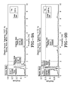
- FIGS. 1 and 2 work well, relying on tire-based sensors for static load input or the VIMS approach adds complicity to achievement of satisfactory load estimation. Consequently, the subject system and methodology as shown in FIG. 4 avoids the use of static load measurement in obtaining the loading state of a vehicle.
- a change in the vehicle 34 loading condition is detected by measuring vibration resonant frequency peaks (bounce mode and/or pitch mode) of the sprung mass. Signals required include the chassis vertical acceleration and/or chassis pitch rate; signals available from a standard 6-axis inertial measurement unit (IMU) commercially available in the market. For real time implementation, a short time Fourier transform approach is used.
- IMU 6-axis inertial measurement unit
- the on vehicle sensor measurements are input into the tire deflection observer 28 previously described to include a quarter vehicle model 22 and filter 20. Additional inputs are derived from tire-based TPMS sensors and include inflation pressure and tire identification from which tire vertical stiffness for the observer model may be determined.
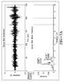
- FIG. 5A shows a sprung mass (chassis) vibration response curve wherein body bounce and wheel hop peaks are designated for a sprung mass.
- FIG. 5B the load sensitivity of a sprung mass (chassis) vibration response curve is shown for both driver-only loading a heavy load condition.
- Human factors considerations dictate that suspension components are selected so that any lightly damped motions are low in frequency.
- vehicle handling considerations demand finite component stiffness, restricting the range of natural frequencies observed in realistic passenger vehicles to a relatively tight band, typically on the order of 1.5 Hz (+/- 1 ⁇ 2 Hz) for passenger sedans shown in FIG. 5A and 2 to 4 Hz for sports cars.
- Heavy truck suspension natural frequencies have a broader range, from 1 Hz to 2.5 Hz.
- Increased load causes a measurable decrease in response frequency as shown in FIG. 5B .
- the presence of the load results in a delay of the "bounce" experienced by the car (i.e. the 2 nd peak in the response trace comes later for the loaded case).
- the frequency differential is measurable, distinguishable and greater than an amplitude difference.
- this peak frequency typically 1 to 3 Hz is reduced when the vehicle mass is increased as shown in FIG. 5B .
- the load variation can be anywhere between 100 to 150 percent, empty vs. full.
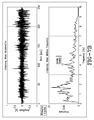
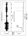
- FIGS. 6A and 6B graphically show sprung mass (chassis) vibration response sensitivity and frequency dropping 28 percent from empty cycle of FIG. 6A to loaded cycle of FIG. 6B .
- the chassis bounce frequency in FIG. 6A is 1.621 Hz and 1.172 Hz in FIG. 6B .
- More validation is shown in FIGS. 7A through 7D .
- FIG. 7A shows sprung mass acceleration and sprung mass motion frequency under empty load cycle.
- FIG. 7B shows unsprung mass acceleration and mass motion frequency in the empty load cycle.
- FIGS. 7C and 7D respectively show sprung mass acceleration and motion frequency and unsprung acceleration and mass motion frequency in the loaded cycle condition.
- FIGS. 8A and 8B The effect of mass variation is further illustrated graphically by FIGS. 8A and 8B .
- Variation in mass is 50 to 100 percent of initial value. Mass perturbation for amplitude in bounce and pitch modes is shown. It should be noted that variations in the mass will also be realized by the moment of inertia since it is a function of mass as well as radius of gyration. Changes in pitch would accordingly be expected since a variation inertial would have an effect on vehicle rotation in the vertical plane. Information about the vehicle pitch frequency may also be used to derive information about the vehicle loading state. Sprung mass (chassis) vibration response load sensitivity is shown further in FIGS. 9A (empty cycle) and 9B (loaded cycle). From FIG. 9A and 9B , a peak frequency drop of 28 percent was empirically detected.
- a short time Fourier transform (STFT) function is recommended.
- STFT operates on a small section of the data. After the transform is complete on one section of the data, the next selection is transformed, and the output "stacked" next to the previous transform output.
- FIG. 10A sprung mass acceleration amplitude over time is shown.
- FIG. 10B sprung mass motion frequency is shown identifying pitch, bounce, and hop peaks.
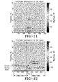
- FIGS. 11 and 12 show the amplitude spectrogram of the signal is shown as frequency over time. It will be appreciated from a comparison of FIGS. 10A, 10B , to FIGS. 11 and 12 , that STFT time and frequency information simultaneously may be used for real time event detection algorithms.
Abstract
Description
- The invention relates generally to systems for indirectly estimating a vehicle's loading condition based upon analytic assessment of vehicle operating parameters.
- The loading condition of a vehicle may be measured by various techniques and methodologies. For example, vehicle-mounted tires may be equipped with strain sensors that detect and measure the deflection of each tire from tire loading. By measuring tire deflection, and thereby the vehicle's loading condition (full, half-full, empty), systems such as stability/brake/ traction control systems may be adjusted as a function of the loading condition. Of particular importance is the determination of loading in off-road vehicles such as mining trucks that may operate under full or partial loaded conditions during normal operation. While measuring vehicle loading through evaluation of tire deformation is an effective technique, factors that affect tire deformation such as road condition, sensor dependability, and operating conditions (i.e. inflation pressure, temperature, aging) can make the accuracy of a tire-deflection determination problematic. It is accordingly desirable to be able to estimate a vehicle's load condition by indirect measurement of the vehicle loading condition, independently of any tire-mounted load sensor. A suitable indirect methodology and system would preferably use commonly available vehicle measured parameters in order to minimize the cost and complexity of load estimation system integration.
- The invention relates to a tire load estimation system in accordance with
claim claim 12. Dependent claims refer to preferred embodiments of the invention. - According to one aspect of the invention a system and method estimating a vehicle tire load is disclosed that identifies a change in vehicle loading condition by measuring vibration resonant frequency peaks (bounce mode and/or pitch mode) of the sprung mass. Signals required include the chassis vertical acceleration and/or chassis pitch rate obtained from commercially available sensors mounted to the vehicle. An observer model receives the inertial signal(s) and generates a dynamic load estimation based upon observed frequency change in the sprung mass natural frequency.
- "ANN" or "Artificial Neural Network" is an adaptive tool for non-linear statistical data modeling that changes its structure based on external or internal information that flows through a network during a learning phase. ANN neural networks are nonlinear statistical data modeling tools used to model complex relationships between inputs and outputs or to find patterns in data.
- "Axial" and "axially" means lines or directions that are parallel to the axis of rotation of the tire.
- "CAN bus" or "controller area network" is a vehicle bus standard designed to allow microcontrollers and devices to communicate with each other within a vehicle without a host computer. CAN bus is a message-based protocol, designed specifically for automotive applications.
- "Circumferential" means lines or directions extending along the perimeter of the surface of the annular tread perpendicular to the axial direction.
- "Kalman Filter" is a set of mathematical equations that implement a predictor-corrector type estimator that is optimal in the sense that it minimizes the estimated error covariance when some presumed conditions are met.
- "Lateral" means an axial direction.
- "Luenberger Observer" is a state observer or estimation model. A "state observer" is a system that provide an estimate of the internal state of a given real system, from measurements of the input and output of the real system. It is typically computer-implemented, and provides the basis of many practical applications.
- "Piezoelectric Film Sensor" a device in the form of a film body that uses the piezoelectric effect actuated by a bending of the film body to measure pressure, acceleration, strain or force by converting them to an electrical charge.
- "Radial" and "radially" means directions radially toward or away from the axis of rotation of the tire.
- "Slip Angle" is the angle between a vehicle's direction of ravel and the direction in which the front wheels are pointing. Slip angle is a measurement of the deviation between the plane of tire rotation and the direction of travel of a tire.
- "Vibration Spectral Analysis" is a methodology for analyzing a machine vibration spectrum using velocity, displacement, acceleration versus frequency.
- The invention will be described by way of example and with reference to the accompanying drawings in which:
-
FIG. 1 is a schematic representation of the tire deflection and load estimation system. -
FIG. 2 is a schematic representation of a system using an actual tire load measuring sensor. -
FIG. 3A is a graph of actual vs. estimated load estimation results at 100 kph speed at a tire inflation about 220600 Pa (32 psi), using a correlation coefficient (R) = 0.926. -
FIG. 3B is a graph of actual vs. estimated load estimation results at 100 kph speed at a tire inflation of about 220600 Pa (32 psi)., using a correlation coefficient (R) = 0.839. -
FIG. 4 is a schematic of a health monitoring system for off-road tires. -
FIG. 5A is a sprung mass (chassis) vibration response graph showing body bounce and wheel hop peak amplitude vs. frequency. -
FIG. 5B is a sprung mass (chassis) vibration response graph showing load sensitivity. -
FIG. 6A is a sprung mass (chassis) vibration response graph showing load sensitivity for chassis bounce frequency at 1.621 Hz. -
FIG. 6B is a sprung mass (chassis) vibration response graph showing load sensitivity for chassis bounce frequency at 1.172 Hz. -
FIG. 7A is a graph showing sprung mass acceleration amplitude over time and sprung mass motion frequency. -
FIG. 7B is a graph showing unsprung mass acceleration amplitude over time and unsprung mass motion frequency amplitude vs. frequency spectrum. -
FIG. 7C is a graph showing sprung mass acceleration amplitude over time and sprung mass motion frequency amplitude. -
FIG. 7D is a graph showing unsprung mass acceleration unsprung mass motion frequency for a loaded cycle. -
FIGS. 8A and 8B are respective graphs showing mass perturbation for amplitude in bounce and pitch modes. -
FIGS. 9A and 9B are graphs showing sprung mass motion frequency for chassis bounce frequencies of 1.621 and 1.172 Hz, respectively. -
FIGS. 10A and 10B are real time implementation time-frequency graphs showing the use of a short time Fourier transform (STFT) function implementation. -
FIG. 11 is an amplitude spectogram of the signal. -
FIG. 12 is a time-frequency analysis of a combined cycle of an empty truck vs. a loaded truck demonstrating the detection of a drop in frequency. -
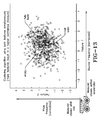
FIG. 13 is a graph showing a clustering algorithm using both features of measured chassis pitch rate and measured chassis vertical acceleration simultaneously. - Referring first to
FIG. 2 and3A , asystem 10 and method for estimating an instantaneous tire load is shown schematically byFIG. 2 . Atire 12 supports avehicle 14. Each of thetires 12 is equipped with a tire pressure monitoring device (TPMS) (not shown) of commercially available configuration affixed to a tire component such as a tire inner liner by suitable means such as adhesive. The TPMS device is equipped with an air pressure measuring sensor for measuring air pressure within a tire cavity as well as tire identification data. A transmitter for transmitting the measured pressure and tire ID data to a vehicle-based data processing receiver is included within the TPMS device. On vehicle sensors convey throughCAN bus 16 sensor data from a hub accelerometer mounted to the wheel hub and a chassis mounted chassis accelerometer. The sensor data from the accelerometers are transmitted to a data processing unit that includes anobserver 18, such as but not limited to a Kalman filter, that functions utilizing Kalman-filtering techniques. The Kalmanlinear filter 20 estimates the vertical deflection of thetire 12 by applying estimation techniques based on the "quarter car model" 22 shown inFIG. 2 in which: - Zs = chassis vertical deflection as measured by accelerometer;
- Zu = Hub vertical deflection as measured by accelerometer;
- Zr = Wheel vertical deflection;
- Ksuspension = suspension stiffness;
- Csuspension = suspension dampening coefficient;
- Ktire = tire stiffness;
- Ctire = tire dampening coefficient;
- Ms = sprung mass;
- Mu = unsprung mass.
- The standard notational convention for describing a State-space representation is given by:
- x' = A x + B u} state equations;
- y = C x + D u} output equations;
- x(t) State vector;
- x'(t) Derivative of state vector;
- A State matrix;
- B Input matrix;
- u(t) Input vector;
- y(t) output vector;
- C output matrix;
- D Direct transmission matrix
- The equivalent state space representation of the "quarter car model" used in the Kalman filter has been specified below as.

1000;
0001;


- Estimated states of the Kalman
linear filter 28 are (Zs'-Zu'), (Zs-Zu), (Zu-Zr) and (Zu'-Zr'). The state estimations are input into aload variation estimator 30 and utilized within the expression:
- The
Kalman Filter 20, in performing its state estimation, further utilizes a tire nominal static load in conjunction with the tire stiffness information. The static load estimation is generated by tire attached sensors. The TPMS system produces tire identification and inflations data which is used to consult and extract tire stiffness Ktire from a tire-specific database. The load variation fromload variation estimator 24 is calculated by use of expression (1), fusing the tire deflection information with the tire load and stiffness information. - In order to verify the accuracy of the instantaneous load estimation, actual loading on a
tire 12 is measured in theFIG. 2 experimental physical system by a force hub anddisplay 26. The estimated instantaneous load ontire 12 is compared against the actual loading on the tire and the comparison is indicated graphically byFIGS. 3A and 3B . The estimated load fromFIG. 2 load variation estimator 24 is compared to the actual tire load Fz from the force hub. InFIG. 3A , the load (N) over time is graphed at a vehicle speed of 100 kph, and a tire inflation of about 220600 Pa (32 psi). It will be seen fromFIG. 3A and FIG. 3B that the actual loading (measured by the force hub) and the estimated instantaneous load estimation made by the system andmethod 10 ofFIG. 2 compare favorably and achieve an estimation correlation of (R) = 0.926. InFIG. 3B , the estimation performance is graphed for a 3mm x 25 mm cleat, showing load vs. time for actual using a force hub and estimated using a Kalman filter. - The "quarter car model" 22 estimation scheme is shown in schematic detail by
FIG. 1 . In the estimation, theKalman filter 20 analyzes suspension reaction of a quarter car model traversing aground surface 28. Measuring the vertical deflection of the vehicle system to undulations present in theroad surface 28, a chassis-mounted accelerometer measures chassis vertical acceleration Zs, while a hub-mounted accelerometer measures wheel hub vertical acceleration Zu. The acceleration parameters Zs" and Zu" input into the tire deflection estimator 20 (Linear Kalman Filter). Tire defection is estimated by theKalman Filter 20 and a first output, representing the tire deflection, is expressed by (Zu-Zr). In the schematic representation ofFIG. 1 , static loading on the tire is indicated as being derived from aVIMS® System 30. "VIMS®" is a proprietary "Vital Information Management System" of Caterpillar Company that integrates monitors on off-road vehicles to provide critical information on a real-time basis. The system exports data to control processors that quantify haul road conditions. The purpose of the Caterpillar VIMS system is to optimize speed on grades in order to better manage payload and to provide check event logs for high brake temperatures, engine over-speeds, etc. The subject invention, as explained below, dispenses with the need for an ancillary system such as the Caterpillar VIMS system in supplying static loading data. The static load from the VIMS system ofFIG. 1 is fed to atire load estimator 32 which also receives the load variation estimation from equation (1) above. Using the status load information from tire attached sensors and the load variation estimated by theKalman Filter 20, an instantaneous load estimate Fz instanteous is made by using equation (2) below.
- Static loading on the
tire 12 may alternatively be estimated by conducting a tire deformation analysis such as that described inUS-B-8,661,885 , incorporated herein in its entirety by reference. The static load Fz static from a tire-attached, deformation-measuring, sensor is then available for use by theKalman filter 20 as described previously. The physical system ofFIG. 1 displays load estimation results that compare favorably with theFIG. 2 actual load force hub measurements. - As a result, the tire vertical deflection, reconstructed using the quarter car model, is sufficiently accurate for the purpose of providing an instantaneous load estimation. The chassis and hub mounted accelerometers used in physical system of
FIG. 2 allows for a successful implementation of the observer using Kalman filtering techniques, and results in an acceptable correlation between actual and estimated load values. - The systems shown in
FIGS. 1 and2 thus use Kalman filtering techniques to estimate the vertical deflection of a tire by starting with the measures of the vehicle suspension dynamics. The observer is based on a "quarter car model". From the static load input (either VIMS-generated or tire-sensor derived) and vehicle suspension dynamics, an instantaneous load on a tire may be calculated. Tire attached TPMS data (inflation pressure and tire identification) is used to determine tire stiffness by application of a tire-specific database. The tire stiffness is used with a sensor or VIMS load (static) estimate obtained from tire based sensors (as inUS-B-8,661,885 ) and fused with the instantaneous load variation estimate (using the tire deflection information) to yield an instantaneous load estimation. - While the systems and methodologies manifest in
FIGS. 1 and2 work well, relying on tire-based sensors for static load input or the VIMS approach adds complicity to achievement of satisfactory load estimation. Consequently, the subject system and methodology as shown inFIG. 4 avoids the use of static load measurement in obtaining the loading state of a vehicle. A change in thevehicle 34 loading condition is detected by measuring vibration resonant frequency peaks (bounce mode and/or pitch mode) of the sprung mass. Signals required include the chassis vertical acceleration and/or chassis pitch rate; signals available from a standard 6-axis inertial measurement unit (IMU) commercially available in the market. For real time implementation, a short time Fourier transform approach is used. The on vehicle sensor measurements are input into thetire deflection observer 28 previously described to include aquarter vehicle model 22 andfilter 20. Additional inputs are derived from tire-based TPMS sensors and include inflation pressure and tire identification from which tire vertical stiffness for the observer model may be determined. -
FIG. 5A shows a sprung mass (chassis) vibration response curve wherein body bounce and wheel hop peaks are designated for a sprung mass. InFIG. 5B , the load sensitivity of a sprung mass (chassis) vibration response curve is shown for both driver-only loading a heavy load condition. Human factors considerations dictate that suspension components are selected so that any lightly damped motions are low in frequency. On the other hand, vehicle handling considerations demand finite component stiffness, restricting the range of natural frequencies observed in realistic passenger vehicles to a relatively tight band, typically on the order of 1.5 Hz (+/- ½ Hz) for passenger sedans shown inFIG. 5A and2 to 4 Hz for sports cars. Heavy truck suspension natural frequencies have a broader range, from 1 Hz to 2.5 Hz. - Increased load causes a measurable decrease in response frequency as shown in
FIG. 5B . The presence of the load results in a delay of the "bounce" experienced by the car (i.e. the 2nd peak in the response trace comes later for the loaded case). The frequency differential is measurable, distinguishable and greater than an amplitude difference. As seen, this peak frequency, typically 1 to 3 Hz is reduced when the vehicle mass is increased as shown inFIG. 5B . Thus a downward shift in the peak frequency response indicates the addition of load to the vehicle. For off-road vehicles such as trucks used in mining operations, the load variation can be anywhere between 100 to 150 percent, empty vs. full. -
FIGS. 6A and 6B graphically show sprung mass (chassis) vibration response sensitivity and frequency dropping 28 percent from empty cycle ofFIG. 6A to loaded cycle ofFIG. 6B . The chassis bounce frequency inFIG. 6A is 1.621 Hz and 1.172 Hz inFIG. 6B . More validation is shown inFIGS. 7A through 7D .FIG. 7A shows sprung mass acceleration and sprung mass motion frequency under empty load cycle.FIG. 7B shows unsprung mass acceleration and mass motion frequency in the empty load cycle.FIGS. 7C and7D respectively show sprung mass acceleration and motion frequency and unsprung acceleration and mass motion frequency in the loaded cycle condition. - The effect of mass variation is further illustrated graphically by
FIGS. 8A and 8B . Variation in mass is 50 to 100 percent of initial value. Mass perturbation for amplitude in bounce and pitch modes is shown. It should be noted that variations in the mass will also be realized by the moment of inertia since it is a function of mass as well as radius of gyration. Changes in pitch would accordingly be expected since a variation in inertial would have an effect on vehicle rotation in the vertical plane. Information about the vehicle pitch frequency may also be used to derive information about the vehicle loading state. Sprung mass (chassis) vibration response load sensitivity is shown further inFIGS. 9A (empty cycle) and 9B (loaded cycle). FromFIG. 9A and 9B , a peak frequency drop of 28 percent was empirically detected. - For real time implementation, a short time Fourier transform (STFT) function is recommended. The STFT operates on a small section of the data. After the transform is complete on one section of the data, the next selection is transformed, and the output "stacked" next to the previous transform output. In
FIG. 10A sprung mass acceleration amplitude over time is shown. InFIG. 10B sprung mass motion frequency is shown identifying pitch, bounce, and hop peaks.FIGS. 11 and 12 show the amplitude spectrogram of the signal is shown as frequency over time. It will be appreciated from a comparison ofFIGS. 10A, 10B , toFIGS. 11 and 12 , that STFT time and frequency information simultaneously may be used for real time event detection algorithms. - From the empirical test results, it will be appreciated that it is possible to detect a change in the loading condition on a vehicle by measuring vibration resonant frequency peaks in the bounce mode and/or pitch mode of the sprung mass. A drop in frequency denotes a movement in vehicle loading between empty and fully loaded conditions. In
FIG. 13 , a clustering algorithm output is graphically shown using both features simultaneously. The more features (such as pitch frequency and bounce frequency) used results in a higher confidence measure. As seen inFIG. 13 , empty, half-loaded, and fully laden conditions are clearly delineated and an estimation of such conditions may be made from measured chassis pitch rate and/or measured chassis vertical acceleration. - From the foregoing description of the subject load estimation system and method, it will be noted that the need for a measurement of static load (whether from a tire-based strain sensor or the VIMS system) is eliminated. The system and method may be extended to any automobile or truck type. Stability/brake/traction control system settings may be adjusted as a function of the loading conditions. Since the signals required are typically available on the vehicle CAN network for cars and trucks, no additional hardware cost would be involved from the implementation of the subject estimation system and method.
Claims (14)
- A tire load estimation system for a vehicle comprising:a tire (12) carried by a hub and supporting a vehicle chassis, the vehicle chassis generating a vibration resonant frequency;a hub-acceleration sensor mounted to the vehicle (34) operative to determine hub acceleration;an inertial measurement unit mounted to the chassis operatively connected to generate at least one chassis inertial signal taken from the group comprising chassis vertical acceleration signal and chassis pitch rate signal;a static load estimator operative to generate an estimated static load from the at least one chassis inertial signal;a sensor mounted to the tire (12) operative to measure tire inflation pressure;a tire vertical stiffness generator operative to determine a tire-specific tire vertical stiffness from the measured tire inflation pressure; anda tire deflection observer operative to calculate a dynamic load from the estimated static load, the chassis vertical acceleration, the hub acceleration, and the tire vertical stiffness.
- The tire load estimation system according to claim 1, wherein the tire deflection observer comprises a load variation estimator.
- The tire load estimation system according to claim 2, wherein the load variation estimator is operative to estimate a dynamic load on the tire from an observed change in frequency peaks within the vibration resonant frequency of the at least one chassis inertial signal.
- The tire load estimation system of claim 1, 2 or 3, wherein the inertial measurement unit comprises a six-axis inertial measurement device mounted to the vehicle (34).
- The tire load estimation system of at least one of the previous claims, wherein the tire deflection observer comprises a Kalman filter (20) model.
- The tire load estimation system of at least one of the previous claims, further comprising an accessible tire-identification device mounted to the tire (12) operative to make a tire-specific identification.
- The tire load estimation system of at least one of the previous claims, wherein the vertical stiffness generator comprises an accessible tire-specific stiffness database adjusted for tire inflation pressure based upon the tire-specific identification of a given tire.
- A tire load estimation system for a vehicle comprising:a tire-supported vehicle chassis, the vehicle chassis generating a vibration sprung mass natural frequency in at least a bounce mode or a pitch mode of the sprung mass;an inertial measurement unit mounted to the chassis operatively connected to generate at least one chassis inertial signal taken from the group comprising a chassis vertical acceleration signal and a chassis pitch rate signal;an observer model receiving the at least one inertial signal and operative to generate a dynamic load estimation based upon observed frequency change in the sprung mass natural frequency.
- The tire load estimation system of claim 8, further comprising:a static load estimator operative to generate an estimated static load from the at least one chassis inertial signal;a sensor mounted to the tire operative to measure tire inflation pressure;a tire vertical stiffness generator operative to determine a tire-specific tire vertical stiffness from the measured tire inflation pressure;wherein the observer model is operative to determine a tire deflection estimation from the estimated static load, the chassis vertical acceleration, the hub acceleration, and the tire vertical stiffness.
- The tire load estimation system of claim 8 or 9, wherein the inertial measurement unit comprises a six-axis inertial measurement device mounted to the vehicle chassis.
- The tire load estimation system of at least one of the previous claims, wherein the observer model comprises a Kalman filter model.
- A tire load estimation method for a vehicle, the method comprising:observing from tire-supported vehicle chassis a vibration sprung mass natural frequency in at least a bounce mode or a pitch mode of the sprung mass;securing from an inertial measurement unit mounted to the chassis at least one chassis inertial signal taken from the group comprising a chassis vertical acceleration signal and a chassis pitch rate signal;utilizing an observer model receiving the at least one inertial signal to generate a dynamic load estimation of a loading of the tire-supported vehicle chassis based upon observed frequency change in the sprung mass natural frequency of the vehicle chassis.
- The tire load estimation method of claim 12, further comprising utilizing a chassis-mounted a six-axis inertial measurement device mounted to the vehicle chassis for securing the at least one chassis inertial signal.
- The tire load estimation method of claim 12 or 13, wherein the observer model comprises a Kalman filter (20) model.
Applications Claiming Priority (1)
| Application Number | Priority Date | Filing Date | Title |
|---|---|---|---|
| US14/526,848 US10048170B2 (en) | 2014-10-29 | 2014-10-29 | Vehicle loading condition detection system and method |
Publications (2)
| Publication Number | Publication Date |
|---|---|
| EP3015841A2 true EP3015841A2 (en) | 2016-05-04 |
| EP3015841A3 EP3015841A3 (en) | 2016-05-11 |
Family
ID=54359900
Family Applications (1)
| Application Number | Title | Priority Date | Filing Date |
|---|---|---|---|
| EP15190494.3A Ceased EP3015841A3 (en) | 2014-10-29 | 2015-10-20 | Vehicle loading condition detection system and method |
Country Status (2)
| Country | Link |
|---|---|
| US (1) | US10048170B2 (en) |
| EP (1) | EP3015841A3 (en) |
Cited By (2)
| Publication number | Priority date | Publication date | Assignee | Title |
|---|---|---|---|---|
| CN107808056A (en) * | 2017-10-30 | 2018-03-16 | 四川长虹空调有限公司 | Compressor of air conditioner pipe arrangement vibration reliability appraisal procedure |
| WO2020259877A1 (en) * | 2019-06-25 | 2020-12-30 | Zf Friedrichshafen Ag | Method for testing the tyre pressure of a vehicle |
Families Citing this family (7)
| Publication number | Priority date | Publication date | Assignee | Title |
|---|---|---|---|---|
| US9821611B2 (en) * | 2015-10-21 | 2017-11-21 | The Goodyear Tire & Rubber Company | Indirect tire wear state estimation system |
| KR101953565B1 (en) * | 2016-11-02 | 2019-03-04 | 현대자동차주식회사 | System and Operating Method For Tire Pressure Monitoring |
| DE102017207620B4 (en) * | 2017-05-05 | 2019-05-29 | Continental Automotive Gmbh | Method and device for determining wheel loads on wheels of a vehicle |
| US10356972B2 (en) | 2017-08-01 | 2019-07-23 | Cnh Industrial America Llc | System and method for reducing variations in the penetration depths of ground-engaging tools of an agricultural implement based on monitored tire pressures |
| CN110823484A (en) * | 2018-08-10 | 2020-02-21 | 广州小鹏汽车科技有限公司 | Vehicle safety monitoring method, device, medium and equipment |
| US11906959B2 (en) | 2021-04-07 | 2024-02-20 | Bridgestone Americas Tire Operations, Llc | Off the road tire maintenance using machine learning |
| CN114993529A (en) * | 2022-04-12 | 2022-09-02 | 中国第一汽车股份有限公司 | Four-upright actuator load testing system and testing method |
Citations (1)
| Publication number | Priority date | Publication date | Assignee | Title |
|---|---|---|---|---|
| US8661885B1 (en) | 2012-09-11 | 2014-03-04 | The Goodyear Tire & Rubber Company | Tire sidewall load estimation system and method |
Family Cites Families (14)
| Publication number | Priority date | Publication date | Assignee | Title |
|---|---|---|---|---|
| US6223108B1 (en) * | 1997-05-22 | 2001-04-24 | Honda Giken Kogyo Kabushiki Kaisha | Tire contact load control system |
| JP2004500561A (en) | 1999-12-22 | 2004-01-08 | ピレリ・プネウマティチ・ソチエタ・ペル・アツィオーニ | Method and system for monitoring tire deformation during operation |
| DE10160059A1 (en) | 2000-12-30 | 2002-08-01 | Bosch Gmbh Robert | Accurate determination of motor vehicle loading from measurements of the normal force component acting between a wheel contact surface and the driving surface |
| US6759952B2 (en) | 2001-07-06 | 2004-07-06 | Trw Inc. | Tire and suspension warning and monitoring system |
| WO2005005950A1 (en) | 2003-07-04 | 2005-01-20 | Pirelli Pneumatici S.P.A. | Method and system for determining a tyre load during the running of a motor vehicle |
| EP1675735B1 (en) | 2003-10-24 | 2016-02-17 | Pirelli Tyre S.p.A. | Method and system for determining a tyre load during the running of a vehicle |
| JP4680532B2 (en) | 2004-06-02 | 2011-05-11 | 株式会社ブリヂストン | Method and apparatus for estimating dynamic state of tire |
| US20070006652A1 (en) | 2005-07-06 | 2007-01-11 | Abnaki Systems, Inc. | Load measuring sensor and method |
| FR2890904B1 (en) * | 2005-09-22 | 2007-12-14 | Peugeot Citroen Automobiles Sa | SUSPENSION CONTROL DEVICE, VEHICLE PROVIDED WITH SAME, METHOD OF OBTAINING AND PROGRAM |
| US7885750B2 (en) * | 2006-08-30 | 2011-02-08 | Ford Global Technologies | Integrated control system for stability control of yaw, roll and lateral motion of a driving vehicle using an integrated sensing system to determine a sideslip angle |
| IT1393072B1 (en) | 2008-10-24 | 2012-04-11 | Pirelli | METHOD AND SYSTEM FOR REPORTING A CONDITION OF AQUAPLANO OF A TIRE ASSEMBLED ON A VEHICLE |
| EP2812661B1 (en) | 2012-02-10 | 2019-11-27 | Appareo Systems, LLC | Frequency-adaptable structural health and usage monitoring system |
| US9874496B2 (en) | 2013-03-12 | 2018-01-23 | The Goodyear Tire & Rubber Company | Tire suspension fusion system for estimation of tire deflection and tire load |
| US9222854B2 (en) | 2013-03-12 | 2015-12-29 | The Goodyear Tire & Rubber Company | Vehicle dynamic load estimation system and method |
-
2014
- 2014-10-29 US US14/526,848 patent/US10048170B2/en active Active
-
2015
- 2015-10-20 EP EP15190494.3A patent/EP3015841A3/en not_active Ceased
Patent Citations (1)
| Publication number | Priority date | Publication date | Assignee | Title |
|---|---|---|---|---|
| US8661885B1 (en) | 2012-09-11 | 2014-03-04 | The Goodyear Tire & Rubber Company | Tire sidewall load estimation system and method |
Cited By (3)
| Publication number | Priority date | Publication date | Assignee | Title |
|---|---|---|---|---|
| CN107808056A (en) * | 2017-10-30 | 2018-03-16 | 四川长虹空调有限公司 | Compressor of air conditioner pipe arrangement vibration reliability appraisal procedure |
| WO2020259877A1 (en) * | 2019-06-25 | 2020-12-30 | Zf Friedrichshafen Ag | Method for testing the tyre pressure of a vehicle |
| US11760140B2 (en) | 2019-06-25 | 2023-09-19 | Zf Friedrichshafen Ag | Mechanically oscillated method for testing the tire pressure of a vehicle |
Also Published As
| Publication number | Publication date |
|---|---|
| US10048170B2 (en) | 2018-08-14 |
| EP3015841A3 (en) | 2016-05-11 |
| US20160121668A1 (en) | 2016-05-05 |
Similar Documents
| Publication | Publication Date | Title |
|---|---|---|
| EP3015841A2 (en) | Vehicle loading condition detection system and method | |
| EP2777956B1 (en) | Tire suspension fusion system for estimation of tire deflection and tire load and method of estimating a tire load | |
| EP3023761B1 (en) | Tire cornering stiffness estimation system and method | |
| EP2837510B1 (en) | Torsional mode tire wear state estimation system and method | |
| EP3421267B1 (en) | Tire wear state estimation system and method | |
| EP3153375B1 (en) | Robust tire forces estimation system | |
| EP3153374B1 (en) | Method for estimating tire forces from can-bus accessible sensor inputs | |
| EP3115765B1 (en) | Tire sensor-based vehicle state estimation system and method | |
| EP2778631B1 (en) | Vehicle dynamic load estimation system and method | |
| EP2774784B1 (en) | Tire load estimation system and method using road profile adaptive filtering | |
| EP2813378B1 (en) | Tire wear state estimation system and method | |
| EP3020578B1 (en) | Tire wear compensated load estimation system and method | |
| EP2722202B1 (en) | Vehicle tire load estimation | |
| EP3028910B1 (en) | Slip ratio point optimization system and method for vehicle control | |
| EP1798077B1 (en) | Apparatus, method and program for alarming decrease in tire air-pressure | |
| EP2865572A1 (en) | Road friction estimation system and method | |
| EP3028909A1 (en) | Intelligent tire-based road friction estimation system and method | |
| EP1350642A2 (en) | Tire pressure and parameter monitoring system and method using accelerometers | |
| EP3017971B1 (en) | Tire sensor-based vehicle control system optimization and method | |
| EP3028880B1 (en) | Tire lift-off propensity predictive system and method | |
| JP5464580B2 (en) | Tire resonance frequency decompression sensitivity estimation apparatus and method, and tire resonance frequency decompression sensitivity estimation program | |
| WO2022066867A1 (en) | Adjustment of indirectly determined values of a tire monitoring system | |
| WO2018030000A1 (en) | Tire mounted sensor, diagnosis history storage device, and diagnosis notification device |
Legal Events
| Date | Code | Title | Description |
|---|---|---|---|
| PUAL | Search report despatched |
Free format text: ORIGINAL CODE: 0009013 |
|
| PUAI | Public reference made under article 153(3) epc to a published international application that has entered the european phase |
Free format text: ORIGINAL CODE: 0009012 |
|
| AK | Designated contracting states |
Kind code of ref document: A2 Designated state(s): AL AT BE BG CH CY CZ DE DK EE ES FI FR GB GR HR HU IE IS IT LI LT LU LV MC MK MT NL NO PL PT RO RS SE SI SK SM TR |
|
| AX | Request for extension of the european patent |
Extension state: BA ME |
|
| AK | Designated contracting states |
Kind code of ref document: A3 Designated state(s): AL AT BE BG CH CY CZ DE DK EE ES FI FR GB GR HR HU IE IS IT LI LT LU LV MC MK MT NL NO PL PT RO RS SE SI SK SM TR |
|
| AX | Request for extension of the european patent |
Extension state: BA ME |
|
| RIC1 | Information provided on ipc code assigned before grant |
Ipc: G01M 17/02 20060101ALI20160407BHEP Ipc: G01M 17/007 20060101AFI20160407BHEP Ipc: B60C 23/04 20060101ALI20160407BHEP Ipc: B60C 23/06 20060101ALI20160407BHEP |
|
| 17P | Request for examination filed |
Effective date: 20161111 |
|
| RBV | Designated contracting states (corrected) |
Designated state(s): AL AT BE BG CH CY CZ DE DK EE ES FI FR GB GR HR HU IE IS IT LI LT LU LV MC MK MT NL NO PL PT RO RS SE SI SK SM TR |
|
| 17Q | First examination report despatched |
Effective date: 20161207 |
|
| STAA | Information on the status of an ep patent application or granted ep patent |
Free format text: STATUS: THE APPLICATION HAS BEEN REFUSED |
|
| 18R | Application refused |
Effective date: 20180127 |