EP3015800A1 - Refrigerator - Google Patents
Refrigerator Download PDFInfo
- Publication number
- EP3015800A1 EP3015800A1 EP14817531.8A EP14817531A EP3015800A1 EP 3015800 A1 EP3015800 A1 EP 3015800A1 EP 14817531 A EP14817531 A EP 14817531A EP 3015800 A1 EP3015800 A1 EP 3015800A1
- Authority
- EP
- European Patent Office
- Prior art keywords
- cooler
- air
- heater
- radiating fins
- chamber
- Prior art date
- Legal status (The legal status is an assumption and is not a legal conclusion. Google has not performed a legal analysis and makes no representation as to the accuracy of the status listed.)
- Ceased
Links
Images



Classifications
-
- F—MECHANICAL ENGINEERING; LIGHTING; HEATING; WEAPONS; BLASTING
- F25—REFRIGERATION OR COOLING; COMBINED HEATING AND REFRIGERATION SYSTEMS; HEAT PUMP SYSTEMS; MANUFACTURE OR STORAGE OF ICE; LIQUEFACTION SOLIDIFICATION OF GASES
- F25D—REFRIGERATORS; COLD ROOMS; ICE-BOXES; COOLING OR FREEZING APPARATUS NOT OTHERWISE PROVIDED FOR
- F25D21/00—Defrosting; Preventing frosting; Removing condensed or defrost water
- F25D21/06—Removing frost
- F25D21/08—Removing frost by electric heating
-
- F—MECHANICAL ENGINEERING; LIGHTING; HEATING; WEAPONS; BLASTING
- F25—REFRIGERATION OR COOLING; COMBINED HEATING AND REFRIGERATION SYSTEMS; HEAT PUMP SYSTEMS; MANUFACTURE OR STORAGE OF ICE; LIQUEFACTION SOLIDIFICATION OF GASES
- F25D—REFRIGERATORS; COLD ROOMS; ICE-BOXES; COOLING OR FREEZING APPARATUS NOT OTHERWISE PROVIDED FOR
- F25D2500/00—Problems to be solved
- F25D2500/02—Geometry problems
Definitions
- the present invention relates to an electric refrigerator for cooling and preserving food and the like in storage chambers, and particularly to an electric refrigerator helpful in optimizing a defrosting procedure.
- An ordinary electric refrigerator has a refrigeration cycle device, and a cooler included in the refrigeration cycle device has many radiating fins arranged in parallel and refrigerant pipes contacting the radiating fins.
- the radiating fins have a temperature of about -30°C when air in the refrigerator is cooled in the cooler, and thus moisture contained in the air circulating among the radiating fins is adhered on surfaces of the radiating fins to become solid and frost. This phenomenon is also generally known as frosting.
- the supply of a refrigerant to the cooler is stopped, and the radiating fins are heated by a heater arranged nearby the cooler. Hence, frost adhered on the radiating fins is heated, melted and then removed. After removal, a refrigeration cycle is operating again.
- a cover is arranged between a heater and a cooler so as to prevent water liquefied from frost heated by the heater from dripping onto the heater.
- hot air heated by the heater may not fully achieve the heating effect of the heater even if the ascending hot air is partially hindered by the cover. In this way, defrosting requires a longer time and the electric power required for the electric refrigerator to work increases, which goes against the trend of energy saving.
- the present invention is accomplished in view of the above circumstance and aims to provide an electric refrigerator with a refrigeration cycle capable of effectively defrosting a cooler.
- the electric refrigerator of the present invention is characterized by having: a refrigeration cycle connected with a compressor for compressing a refrigerant, a condenser for condensing the refrigerant, an expansion device for expanding the condensed refrigerant and a cooler for evaporating the expanded refrigerant via a piping; a defrosting heater arranged below the cooler; and a heater cover arranged between the heater and the cooler, wherein the cooler has radiating fins arranged in parallel and refrigerant pipes penetrating through the radiating fins and circulating the refrigerant, both ends of the heater cover are arranged below the refrigerant pipes, and the distance at which a lower end of the lowermost radiating fins is separated from the heater cover in a height direction is longer than the distance at which a side wall of a cooling chamber equipped with the cooler is separated from the ends of the heater cover in a depth direction.
- the both ends of the heater cover are arranged below the refrigerant pipes, and the heater cover is arranged between the radiating fins and the defrosting heater. Accordingly, hot air obtained by heating via the defrosting heater well contacts the refrigerant pipes through the both ends of the heater cover, and thus defrosting can be effectively performed.
- the distance at which the lower end of the lowermost radiating fins is separated from the heater cover in the height direction is set to be longer than the distance at which the side wall of the cooling chamber equipped with the cooler is separated from the ends of the heater cover in a depth direction of the electric refrigerator. Accordingly, air returned from the refrigerating chamber to the cooling chamber can be well introduced between the radiating fins and the heater cover, thereby being capable of reducing loss in an air passage, well cooling the refrigerating chamber and improving the air cooling efficiency of the cooler.
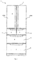
- Fig. 1 is a front view showing the appearance of an outline structure of an electric refrigerator 1 involved in the embodiment.
- Fig. 2 is a right side cross-sectional view of the electric refrigerator 1.
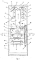
- Fig. 3 is a front sketch showing the outline of air supply passages of the electric refrigerator 1.
- the flow of cold air supplied to storage chambers 3-7 is represented by solid arrows
- the flow of air returned from the storage chambers 3-7 to a cooling chamber 13 is represented by dotted arrows.
- the electric refrigerator 1 has a heat insulating box body 2 as a body and a storage chamber for storing food and the like is formed inside the heat insulating box body 2.
- the storage chamber is internally divided into a plurality of accommodating chambers 3-7 according to the storage temperature or use.
- a refrigerating chamber 3 is located uppermost, below which an ice making chamber 4 is located at a left side and an upper freezing chamber 5 is located at a right side, and further below which a lower freezing chamber 6 is located; and a vegetable chamber 7 is located lowermost.
- the ice making chamber 4, the upper freezing chamber 5 and the lower freezing chamber 6 are accommodating chambers in a freezing temperature region, and therefore are appropriately collectively referred to as freezing chambers 4-6 in the following description.
- the heat insulating box body 2 is provided with openings in the front thereof, and heat insulating doors 8-12 are respectively arranged in a freely opened/closed mode at the opening portions corresponding to the accommodating chambers 3-7.
- Refrigerating chamber doors 8a, 8b divide and block the front face of the refrigerating chamber 3, and upper and lower parts of the left side of the refrigerating chamber door 8a as well as upper and lower parts of the right side of the refrigerating chamber door 8b are rotatably supported by the heat insulating box body 2.
- heat insulating doors 9-12 are supported by the heat insulating box body 2 to be freely pulled out from the front of the electric refrigerator 1.
- the heat insulating box body 2 as the body of the electric refrigerator 1 consists of an outer box 2a made of a steel plate which has opening portions in the front thereof, an inner box 2b made of synthetic resin which is arranged in a spaced manner inside the outer box 2a and has opening portions in the front thereof, and a heat insulating material 2c made of foaming polyurethane which is filled and foamed in the gap between the outer box 2a and the inner box 2b.
- the heat insulating doors 8-12 employ the same insulation structure as the heat insulating box body 2 also.
- the refrigerating chamber 3 and the freezing chambers 4-6 located below the refrigerating chamber are partitioned by a heat insulating partition wall 35.
- the heat insulating partition wall 35 is formed from synthetic resin and internally filled with a heat insulating material.
- the ice making chamber 4 and the upper freezing chamber 5 inside the freezing chambers 4-6 are partitioned by a partition wall (not shown).
- the ice making chamber 4 and the upper freezing chamber 5 are communicated in manner of cold air free circulation with the lower freezing chamber 6 arranged below them.
- the freezing chambers 4-6 and the vegetable chamber 7 are partitioned by a heat insulating partition wall 36.
- the inside of the freezing chambers 4-6 is divided by a partition member made of synthetic resin, i.e. a front face cover 24, to form a freezing chamber air supply passage 14.
- the air supply passage 14 for freezing is a space formed between a partition 25 and the front face cover 24 assembled in front of the partition, i.e. an air passage for circulating cold air cooled by a cooler 33.
- Openings for blowing off cold air to the freezing chambers 4-6, i.e. air outlets 15, are formed in the front face cover 24.
- a return port 20 for returning air from the freezing chambers 4-6 to the cooling chamber 13 is formed at a rear face of a lower part of the lower freezing chamber 6.
- a refrigerating chamber air supply passage 16 for supplying cold air to the refrigerating chamber 3 is formed at a rear face of the refrigerating chamber 3. Air outlets 17 for flowing off cold air to the refrigerating chamber 3 are formed on the refrigerating chamber air supply passage 16.
- the freezing chamber air supply passage 14 is communicated with the refrigerating chamber air supply passage 16 via a refrigerating chamber air door 34a of an air door device 34.
- the refrigerating chamber air door 34a is used for controlling the flow rate of cold air supplied to the refrigerating chamber 3 so as to properly maintain the temperature inside the refrigerating chamber 3.
- the cooling chamber 13 formed by partitioning via the partition 25 is arranged further inside the freezing chamber air supply passage 14 inside the inner box 2b. That is to say, the cooling chamber 13 is a space sandwiched between the inner box 2b and the partition 25.
- An opening 13a for connecting the cooling chamber 13 and the freezing chamber air supply passage 14 is formed on the partition 25 at an upper part of the cooling chamber 13, and the opening 13a is equipped with an air blower 32 for supplying cold air to the storage chambers 3-7.
- an opening 13b for sucking cold air returned from the storage chamber into the cooling chamber 13 is formed below the cooling chamber 13.
- the cooling chamber 13 is internally provided with the cooler 33 (an evaporator) for cooling circulating air.
- the cooler 33 is connected with a compressor 31, a radiator (not shown) and an expansion valve (a capillary tube) (not shown) via a refrigerant piping to form a vapor compression refrigeration cycle loop.
- isobutane (R600a) is used as a refrigerant of the above refrigeration cycle in the electric refrigerator 1 involved in the embodiment.
- the electric refrigerator 1 has an air return passage 21 for directing air to flow from the refrigerating chamber 3 to the cooling chamber 13 (refer to Fig. 2 ).
- a vegetable chamber air supply passage 18 for directing air cooled by the cooler 33 to flow towards the vegetable chamber 7 is formed in front of the air return passage 21.
- the vegetable chamber air supply passage 18 is branched upwards from the freezing chamber air supply passage 14, passes through the inside of the heat insulating partition wall 35 above the freezing chambers 4-6 to divert the direction downwards, and then passes through the inside of the freezing chambers 4-6. Subsequently, the vegetable chamber air supply passage penetrates through the heat insulating partition wall 36 to connect the vegetable chamber 7.
- An opening for blowing off cold air from the vegetable chamber air supply passage 18, i.e. an air outlet 19, is formed in the vegetable chamber 7.
- a vegetable chamber air door 34b for controlling the flow of cold air supplied to the vegetable chamber is arranged in the vegetable chamber air supply passage 18 inside the heat insulating partition wall 35. Hence, the vegetable chamber 7 can be cooled independently from the cooling of the refrigerating chamber 3 and the temperature of the vegetable chamber 7 can be properly controlled.
- a return port 29 is formed in the vegetable chamber 7 so that air in the vegetable chamber 7 flows from the return port 29 to a lower part of the cooling chamber 13 via a vegetable chamber air return passage 23 (refer to Fig. 2 ) and the opening 13b (refer to Fig. 2 ).
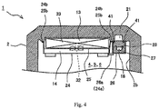
- Fig. 4 is a cross-sectional view illustrating an air supply passage inside the freezing chambers 4-6 of the electric refrigerator 1 and represents an A-A section in Fig. 3 .
- the cooling chamber 13 is formed by dividing via the partition 25 assembled on the inner box 2b, and the cooling chamber 13 is equipped with the cooler 33.
- the freezing chamber air supply passage 14 is formed by dividing between the partition 25 and the front face cover 24 assembled in front of the partition.
- Edge portions 24b, 25b (sealing portions) at two sides of the partition 25 and the front face cover 24 are fixed on the inner box 2b via a sealing member (not shown) using (e.g.) screws and the like. Hence, the airtightness of the cooling chamber 13 or the freezing chamber air supply passage 14 can be improved.
- a vegetable chamber air passage cover 26 is assembled on the cooling chamber 13 inside the freezing chambers 4-6 and the inner box 2b at a right side of the freezing chamber air supply passage 14. Moreover, a space divided by the vegetable chamber air passage cover 26, i.e. a space sandwiched between the vegetable chamber air passage cover 26 and the inner box 2b, is equipped with heat insulating members 27, 28 assembled into a substantially cylindrical shape which forms the vegetable chamber air supply passage 18.
- the heat insulating member 28 and the inner box 2b form the air return passage 21 further inside the vegetable chamber air supply passage 18.
- Sealing members 41 for example, composed of a foamed rubber material and the like are clamped at an engaging portion between the heat insulating member 28 and the inner box 2b to ensure airtightness.
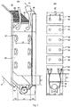
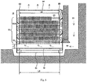
- Fig. 5 the structure of the cooler 33 provided in the electric refrigerator 1 is described.
- Fig. 5(A) is a stereographic view showing the structure of the cooler 33 provided in the cooling chamber 13
- Fig. 5(B) is a cross-sectional view of the cooler 33 observed from its side.
- the cooler 33 consists of a plurality of radiating fins 52 arranged in a width direction at specified intervals, refrigerant pipes 53 arranged in manner of penetrating through the radiating fins 52, and end plates 65 for holding the refrigerant pipes 53 at two ends.
- the refrigerant pipes 53 are bent into a shape by penetrating through the radiating fins 52 of each column, and two refrigerant pipes 53 herein penetrate through each radiating fin 52.
- a defrosting heater 51 that is powered for heating when defrosting is arranged below the radiating fins 52.
- the defrosting heater 51 is formed by holding a heating element in a cylindrical glass tube and has the function of melting frost adhered on the refrigerant pipes 53 and the radiating fins 52.
- a heater cover 54 is arranged between the radiating fins 52 and the defrosting heater 51.
- the heater cover 54 for example, obtained by molding a metal plate into specified shape, functions to prevent moisture formed of melted frost from dripping onto the defrosting heater 51 when frost adhered on the radiating fins 52 is melted in a defrosting procedure.
- the length L9 of the heater cover 54 in a width direction is substantially the same as the width L8 of the cooler 33.
- the cooler 33, the defrosting heater 51 and the heater cover 54 are mounted on the inner box 2b by a mounting tool 64 composed of a resin plate.
- the mounting tool 64 has ribbed plates (not shown) for fixing the refrigerant pipes 53 and ribbed plates 64A for fixing bent forming portions of the refrigerant pipes 53, and the mounting is achieved by supporting the refrigerant pipes 53.
- the cooler 33 and the like with the above structure are accommodated in the cooling chamber 13 formed between the partition 25 and the inner box 2b.
- a defrosting procedure is regularly performed in the cooler 33.
- the action of the compressor 31 and the air blower 32 is stopped, and the cooler 33 stops cooling. Frosting is stopped thereby.
- the defrosting heater 51 is powered for heating so that air heated to high temperature rises and passes between the refrigerant pipes 53 and the radiating fins 52 to melt frost.
- frost contacting the high temperature air is melt into water and drips downwards.
- the water drops are blocked by the heater cover 54, and therefore fail to contact the defrosting heater 51, drip into a dew collecting tray 66 located below the cooler 33 and are discharged outside the electric refrigerator from a drainage hole (not shown).
- the defrosting heater 51 stops being powered to terminate the defrosting procedure. Subsequently, the compressor and the air blower sequentially go into operation after a certain period of time to begin cooling each storage chamber.
- ends of the heater cover 54 are arranged below the position where the refrigerant pipes 53 penetrate through the radiating fins 52, thereby optimizing the flow of air (hot air) heated by the defrosting heater 51 and realizing effective defrosting.
- the heater cover 54 is arranged above the defrosting heater 51 to prevent water from dripping onto the defrosting heater 51. Accordingly, hot air obtained by heating via the defrosting heater 51 rises by passing upwards from the ends of the heater cover 54. The position of the ends of the heater cover 54 therefore has a greater influence on the path of hot air.
- the defrosting efficiency is not necessarily good due to no consideration taken of the relative positional relationship between the refrigerant pipes 53 and the heater cover 54.
- the width L2 in a depth direction of the electric refrigerator at which the refrigerant pipes 53 penetrating through the radiating fins 52 are separated from each other is expanded.
- the width L2 is set to be more than 0.6 times the width L1 of the radiating fins 52.
- both ends of the heater cover 54 are arranged below the refrigerant pipes 53 so as to improve the defrosting efficiency of the defrosting heater 51.
- the width L4 of the heater cover 54 is set to be substantially the same as the width L2 in the depth direction of the electric refrigerator at which the refrigerant pipes 53 are separated.
- the width L4 of the heater cover 54 is greater than the width L3 of the defrosting heater 51 composed of a glass tube.
- L4 is set to be more than twice L3.
- hot air obtained by heating via the defrosting heater 51 passes by the both ends of the heater cover 54 and contacts the lowermost refrigerant pipes 53. Accordingly, the refrigerant is boiling and has thermal movement inside the refrigerant pipes 53, the temperature of the upper refrigerant pipes 53 also rises and the adhered frost is well melted.
- the travel of hot air is represented by bold arrows herein.
- hot air contacting the lowermost refrigerant pipes 53 is branched leftwards and rightwards, thereby contacting other refrigerant pipes 53 arranged above while continuing to rise. Hence, hot air rises in the vicinity of each refrigerant pipe 53 so that frost adhered around the refrigerant pipes 53 can be effectively preferentially melted.
- the position of the both ends of the heater cover 54 is preferably set just below the center of the refrigerant pipes 53 arranged lowermost. In this way, most of the air heated by the defrosting heater 51 contacts the lowermost refrigerant pipes 53 so that the above effect can be significantly exerted.
- a lower end of the lowermost radiating fins 52 is separated from the heater cover 54 at over a specified distance.
- the both ends of the heater cover 54 are arranged below the refrigerant pipes 53 separated as described above so that the width L4 of the heater cover 54 is a greater width, e.g. about 50 mm.
- the distance L5 of the gap between the partition 25 (a side wall of the cooling chamber 13) and the end of the heater cover 54 becomes narrow.
- the distance L6 between the inner box 2b (a side wall of the cooling chamber) and the end of the heater cover also becomes narrow.
- the specific length of L5 and L6 is 14.5 mm, for example.
- the rise of the air is hindered by the heater cover 54 with a greater width to cause greater hindrance to an air passage, thus easily insufficiently cooling the refrigerating chamber.
- the following circumstance can be predicted: the circulating cold air directed to the refrigerating chamber is insufficient when frosting occurs in the cooler 33, thereby causing higher temperature in the refrigerating chamber.
- the distance L7 at which the lower end of the lowermost radiating fins 52 is separated from the heater cover 54 in a height direction is set to be greater than the above L5 or L6 to ensure a larger space therebetween.
- the distance L7 is 25.5 mm, for example.
- a cooler 33 of a comparative example is illustrated.
- the separation distance L2 between the refrigerant pipes 53 is also ensured to be wider, i.e. more than 0.6 times the width L1 of the radiating fins 52.
- frost adhered around the refrigerant pipes 53 can be inhibited from blocking an air passage.
- the width L4 of the heater cover 54 herein is narrower than in the above embodiment. Accordingly, the both ends of the heater cover 54 are not located below the refrigerant pipes 53, but inside the refrigerant pipes 53.
- the defrosting heater 51 in a defrosting procedure, the heated air will rise through the inside of the refrigerant pipes 53 and fails to largely contact the refrigerant pipes 53. Accordingly, the effect of the above embodiment may not be exerted and the efficiency of the defrosting procedure is reduced.
- the width L2 between the refrigerant pipes 53 becomes narrow, i.e. 0.5 times the width L1 of the radiating fins 52.
- the both ends of the heater cover 54 are arranged below the refrigerant pipes 53. Accordingly, when a defrosting procedure is performed by the cooler 33, air heated by the defrosting heater 51 passes by the both ends of the heater cover 54 and contacts the lowermost refrigerant pipes 53. Frost adhered around the refrigerant pipes 53 is therefore effectively melted.
- the distance between the refrigerant pipes 53 is shorter so that frosting begins from the refrigerant pipes 53, thus the gap among the refrigerant pipes 53 is blocked by frost and the cooling efficiency is reduced.
- the cooler 33 of the embodiment inhibits reduced cooling efficiency resulting from frosting by expanding the separation distance L2 between the refrigerant pipes 53.
- the both ends of the heater cover 54 are arranged below the refrigerant pipes 53 so that air heated by the defrosting heater 51 contacts the refrigerant pipes 53, thereby improving the efficiency of the defrosting procedure.
- Fig. 8 the effect of the above embodiment is illustrated.
- the transverse axis represents time and the longitudinal axis represents sensor temperature.
- the results obtained using the cooler 33 of the embodiment shown in Fig. 5 are represented by a solid line and the results obtained using the comparative embodiment shown in Fig. 7(A) are represented by a dotted line.
- the graph also shows that the sensor temperature rises in advance and the defrosting procedure is completed in advance in the cooler 33 of the embodiment shown in the solid line when compared with those in the comparative embodiment shown in the dotted line.
- the time for powering the defrosting heater is 31 min in the embodiment as compared with 35 min required for powering the defrosting heater in the comparative embodiment. Accordingly, the embodiment has the advantages of less time and power required for defrosting than the comparative embodiment.
Landscapes
- Engineering & Computer Science (AREA)
- Chemical & Material Sciences (AREA)
- Combustion & Propulsion (AREA)
- Physics & Mathematics (AREA)
- Mechanical Engineering (AREA)
- Thermal Sciences (AREA)
- General Engineering & Computer Science (AREA)
- Defrosting Systems (AREA)
Abstract
Description
- The present invention relates to an electric refrigerator for cooling and preserving food and the like in storage chambers, and particularly to an electric refrigerator helpful in optimizing a defrosting procedure.
- An ordinary electric refrigerator has a refrigeration cycle device, and a cooler included in the refrigeration cycle device has many radiating fins arranged in parallel and refrigerant pipes contacting the radiating fins.
- The radiating fins have a temperature of about -30°C when air in the refrigerator is cooled in the cooler, and thus moisture contained in the air circulating among the radiating fins is adhered on surfaces of the radiating fins to become solid and frost. This phenomenon is also generally known as frosting.
- When the frosting occurs, the gap among the radiating fins is occupied by frost to hinder the circulation of air. To prevent this phenomenon, defrosting operation is regularly performed.
- In the defrosting operation, the supply of a refrigerant to the cooler is stopped, and the radiating fins are heated by a heater arranged nearby the cooler. Hence, frost adhered on the radiating fins is heated, melted and then removed. After removal, a refrigeration cycle is operating again.
- For example, electric refrigerators with the above defrosting structure are recorded in the following
patent documents 1 to 4. -
- Patent document 1: (Japanese) Laid-Open Publication No.
11-183011 - Patent document 2: (Japanese) Kokai Publication No.
2011-7435 - Patent document 3: (Japanese) Kokai Publication No.
2004-190959 - Patent document 4: (Japanese) Kokai Publication No.
2003-42637 - In an ordinary electric refrigerator, a cover is arranged between a heater and a cooler so as to prevent water liquefied from frost heated by the heater from dripping onto the heater. However, when the cover is arranged above the heater, there is the following case: hot air heated by the heater may not fully achieve the heating effect of the heater even if the ascending hot air is partially hindered by the cover. In this way, defrosting requires a longer time and the electric power required for the electric refrigerator to work increases, which goes against the trend of energy saving.
- The present invention is accomplished in view of the above circumstance and aims to provide an electric refrigerator with a refrigeration cycle capable of effectively defrosting a cooler.
- The electric refrigerator of the present invention is characterized by having: a refrigeration cycle connected with a compressor for compressing a refrigerant, a condenser for condensing the refrigerant, an expansion device for expanding the condensed refrigerant and a cooler for evaporating the expanded refrigerant via a piping; a defrosting heater arranged below the cooler; and a heater cover arranged between the heater and the cooler, wherein the cooler has radiating fins arranged in parallel and refrigerant pipes penetrating through the radiating fins and circulating the refrigerant, both ends of the heater cover are arranged below the refrigerant pipes, and the distance at which a lower end of the lowermost radiating fins is separated from the heater cover in a height direction is longer than the distance at which a side wall of a cooling chamber equipped with the cooler is separated from the ends of the heater cover in a depth direction.
- According to the present invention, the both ends of the heater cover are arranged below the refrigerant pipes, and the heater cover is arranged between the radiating fins and the defrosting heater. Accordingly, hot air obtained by heating via the defrosting heater well contacts the refrigerant pipes through the both ends of the heater cover, and thus defrosting can be effectively performed.
- Moreover, according to the present invention, the distance at which the lower end of the lowermost radiating fins is separated from the heater cover in the height direction is set to be longer than the distance at which the side wall of the cooling chamber equipped with the cooler is separated from the ends of the heater cover in a depth direction of the electric refrigerator. Accordingly, air returned from the refrigerating chamber to the cooling chamber can be well introduced between the radiating fins and the heater cover, thereby being capable of reducing loss in an air passage, well cooling the refrigerating chamber and improving the air cooling efficiency of the cooler.
-
-
Fig. 1 is a front view of the appearance of an electric refrigerator involved in an embodiment of the present invention; -
Fig. 2 is a side cross-sectional view showing an outline structure of the electric refrigerator involved in the embodiment of the present invention; -
Fig. 3 is a front sketch showing air supply passages of the electric refrigerator involved in the embodiment of the present invention; -
Fig. 4 is a cross-sectional view showing an air supply passage inside freezing chambers of the electric refrigerator involved in the embodiment of the present invention; -
Fig. 5 is a view showing the electric refrigerator involved in the embodiment of the present invention, wherein (A) is a stereographic view showing a cooler, and (B) is a cross-sectional view along its side direction; -
Fig. 6 is a view showing the cooler arranged in the electric refrigerator involved in the embodiment of the present invention; -
Fig. 7 is a view showing the electric refrigerator involved in the embodiment of the present invention, wherein (A) and (B) are respectively a cross-sectional view showing a cooler of a comparative example, along its side direction; and -
Fig. 8 is a graph showing the effect of the electric refrigerator involved in the embodiment of the present invention. -
- 1: electric refrigerator; 2: heat insulating box body; 2b: inner box; 3: refrigerating chamber; 4: ice making chamber; 5: upper freezing chamber; 6: lower freezing chamber; 7: vegetable chamber; 13: cooling chamber; 14: air supply passage; 16: air supply passage; 18: air supply passage; 21: air return passage; 24: front surface cover; 25: partition; 26: vegetable chamber air passage cover; 27: heat insulating member; 28: heat insulating member; 35: heat insulating partition wall; 36: heat insulating partition wall; 32: air blower; 31: compressor; 33: cooler; 34: air door device; 34c: drive motor; 40: sealing member; 50: return port; 51: defrosting heater; 52: radiating fin; 53: refrigerant pipe; 54: heater cover; 60: air return passage; 61: return port; 62: vegetable chamber air supply passage; 63: air outlet; 64: mounting tool; 64A: ribbed plate; 65: end plate; 66: dew collecting tray.
- The electric refrigerator involved in the embodiment of the present invention is to be described below in detail according to the drawings.
-
Fig. 1 is a front view showing the appearance of an outline structure of anelectric refrigerator 1 involved in the embodiment.Fig. 2 is a right side cross-sectional view of theelectric refrigerator 1.Fig. 3 is a front sketch showing the outline of air supply passages of theelectric refrigerator 1. In addition, inFigs. 2 and3 , the flow of cold air supplied to storage chambers 3-7 is represented by solid arrows, and the flow of air returned from the storage chambers 3-7 to acooling chamber 13 is represented by dotted arrows. - As shown in
Fig. 1 , theelectric refrigerator 1 has a heatinsulating box body 2 as a body and a storage chamber for storing food and the like is formed inside the heatinsulating box body 2. The storage chamber is internally divided into a plurality of accommodating chambers 3-7 according to the storage temperature or use. Arefrigerating chamber 3 is located uppermost, below which anice making chamber 4 is located at a left side and an upperfreezing chamber 5 is located at a right side, and further below which alower freezing chamber 6 is located; and avegetable chamber 7 is located lowermost. In addition, theice making chamber 4, the upperfreezing chamber 5 and thelower freezing chamber 6 are accommodating chambers in a freezing temperature region, and therefore are appropriately collectively referred to as freezing chambers 4-6 in the following description. - The heat
insulating box body 2 is provided with openings in the front thereof, and heat insulating doors 8-12 are respectively arranged in a freely opened/closed mode at the opening portions corresponding to the accommodating chambers 3-7. Refrigeratingchamber doors chamber 3, and upper and lower parts of the left side of the refrigeratingchamber door 8a as well as upper and lower parts of the right side of the refrigeratingchamber door 8b are rotatably supported by the heatinsulating box body 2. In addition, heat insulating doors 9-12 are supported by the heatinsulating box body 2 to be freely pulled out from the front of theelectric refrigerator 1. - As shown in
Fig. 2 , the heatinsulating box body 2 as the body of theelectric refrigerator 1 consists of anouter box 2a made of a steel plate which has opening portions in the front thereof, aninner box 2b made of synthetic resin which is arranged in a spaced manner inside theouter box 2a and has opening portions in the front thereof, and aheat insulating material 2c made of foaming polyurethane which is filled and foamed in the gap between theouter box 2a and theinner box 2b. Furthermore, the heat insulating doors 8-12 employ the same insulation structure as the heatinsulating box body 2 also. - The refrigerating
chamber 3 and the freezing chambers 4-6 located below the refrigerating chamber are partitioned by a heatinsulating partition wall 35. The heat insulatingpartition wall 35 is formed from synthetic resin and internally filled with a heat insulating material. - In addition, the
ice making chamber 4 and the upperfreezing chamber 5 inside the freezing chambers 4-6 are partitioned by a partition wall (not shown). Theice making chamber 4 and theupper freezing chamber 5 are communicated in manner of cold air free circulation with thelower freezing chamber 6 arranged below them. Moreover, the freezing chambers 4-6 and thevegetable chamber 7 are partitioned by a heat insulatingpartition wall 36. - In addition, the inside of the freezing chambers 4-6 is divided by a partition member made of synthetic resin, i.e. a
front face cover 24, to form a freezing chamberair supply passage 14. In particular, theair supply passage 14 for freezing is a space formed between apartition 25 and thefront face cover 24 assembled in front of the partition, i.e. an air passage for circulating cold air cooled by acooler 33. - Openings for blowing off cold air to the freezing chambers 4-6, i.e.
air outlets 15, are formed in thefront face cover 24. In addition, areturn port 20 for returning air from the freezing chambers 4-6 to thecooling chamber 13 is formed at a rear face of a lower part of thelower freezing chamber 6. - In addition, a refrigerating chamber
air supply passage 16 for supplying cold air to the refrigeratingchamber 3 is formed at a rear face of the refrigeratingchamber 3.Air outlets 17 for flowing off cold air to the refrigeratingchamber 3 are formed on the refrigerating chamberair supply passage 16. The freezing chamberair supply passage 14 is communicated with the refrigerating chamberair supply passage 16 via a refrigeratingchamber air door 34a of anair door device 34. The refrigeratingchamber air door 34a is used for controlling the flow rate of cold air supplied to the refrigeratingchamber 3 so as to properly maintain the temperature inside the refrigeratingchamber 3. - The cooling
chamber 13 formed by partitioning via thepartition 25 is arranged further inside the freezing chamberair supply passage 14 inside theinner box 2b. That is to say, the coolingchamber 13 is a space sandwiched between theinner box 2b and thepartition 25. An opening 13a for connecting the coolingchamber 13 and the freezing chamberair supply passage 14 is formed on thepartition 25 at an upper part of the coolingchamber 13, and the opening 13a is equipped with anair blower 32 for supplying cold air to the storage chambers 3-7. On the other hand, anopening 13b for sucking cold air returned from the storage chamber into the coolingchamber 13 is formed below the coolingchamber 13. - Moreover, the cooling
chamber 13 is internally provided with the cooler 33 (an evaporator) for cooling circulating air. The cooler 33 is connected with acompressor 31, a radiator (not shown) and an expansion valve (a capillary tube) (not shown) via a refrigerant piping to form a vapor compression refrigeration cycle loop. Furthermore, isobutane (R600a) is used as a refrigerant of the above refrigeration cycle in theelectric refrigerator 1 involved in the embodiment. - As shown in
Fig. 3 , theelectric refrigerator 1 has anair return passage 21 for directing air to flow from the refrigeratingchamber 3 to the cooling chamber 13 (refer toFig. 2 ). An opening connected with theair return passage 21, i.e. areturn port 22, is formed at a lower part of the refrigeratingchamber 3. Air in the refrigeratingchamber 3 flows towards theair return passage 21 via thereturn port 22 and then flows downwards the cooler 33. - In addition, a vegetable chamber
air supply passage 18 for directing air cooled by the cooler 33 to flow towards thevegetable chamber 7 is formed in front of theair return passage 21. The vegetable chamberair supply passage 18 is branched upwards from the freezing chamberair supply passage 14, passes through the inside of the heat insulatingpartition wall 35 above the freezing chambers 4-6 to divert the direction downwards, and then passes through the inside of the freezing chambers 4-6. Subsequently, the vegetable chamber air supply passage penetrates through the heat insulatingpartition wall 36 to connect thevegetable chamber 7. An opening for blowing off cold air from the vegetable chamberair supply passage 18, i.e. anair outlet 19, is formed in thevegetable chamber 7. - A vegetable
chamber air door 34b for controlling the flow of cold air supplied to the vegetable chamber is arranged in the vegetable chamberair supply passage 18 inside the heat insulatingpartition wall 35. Hence, thevegetable chamber 7 can be cooled independently from the cooling of the refrigeratingchamber 3 and the temperature of thevegetable chamber 7 can be properly controlled. - In addition, a
return port 29 is formed in thevegetable chamber 7 so that air in thevegetable chamber 7 flows from thereturn port 29 to a lower part of the coolingchamber 13 via a vegetable chamber air return passage 23 (refer toFig. 2 ) and theopening 13b (refer toFig. 2 ). -
Fig. 4 is a cross-sectional view illustrating an air supply passage inside the freezing chambers 4-6 of theelectric refrigerator 1 and represents an A-A section inFig. 3 . - As shown in
Fig. 4 , the coolingchamber 13 is formed by dividing via thepartition 25 assembled on theinner box 2b, and the coolingchamber 13 is equipped with the cooler 33. In addition, the freezing chamberair supply passage 14 is formed by dividing between thepartition 25 and thefront face cover 24 assembled in front of the partition. -
Edge portions partition 25 and thefront face cover 24 are fixed on theinner box 2b via a sealing member (not shown) using (e.g.) screws and the like. Hence, the airtightness of the coolingchamber 13 or the freezing chamberair supply passage 14 can be improved. - A vegetable chamber
air passage cover 26 is assembled on the coolingchamber 13 inside the freezing chambers 4-6 and theinner box 2b at a right side of the freezing chamberair supply passage 14. Moreover, a space divided by the vegetable chamberair passage cover 26, i.e. a space sandwiched between the vegetable chamberair passage cover 26 and theinner box 2b, is equipped withheat insulating members air supply passage 18. - In addition, the
heat insulating member 28 and theinner box 2b form theair return passage 21 further inside the vegetable chamberair supply passage 18.Sealing members 41, for example, composed of a foamed rubber material and the like are clamped at an engaging portion between theheat insulating member 28 and theinner box 2b to ensure airtightness. - Referring to
Fig. 5 , the structure of the cooler 33 provided in theelectric refrigerator 1 is described.Fig. 5(A) is a stereographic view showing the structure of the cooler 33 provided in the coolingchamber 13, andFig. 5(B) is a cross-sectional view of the cooler 33 observed from its side. - Referring to
Fig. 5(A) , the cooler 33 consists of a plurality of radiatingfins 52 arranged in a width direction at specified intervals,refrigerant pipes 53 arranged in manner of penetrating through the radiatingfins 52, andend plates 65 for holding therefrigerant pipes 53 at two ends. Taking a column configured with a specified number of the radiatingfins 52 in a width direction as a unit, multiple columns are arranged at equal intervals in a height direction. In addition, therefrigerant pipes 53 are bent into a shape by penetrating through the radiatingfins 52 of each column, and tworefrigerant pipes 53 herein penetrate through each radiatingfin 52. - A defrosting
heater 51 that is powered for heating when defrosting is arranged below the radiatingfins 52. The defrostingheater 51 is formed by holding a heating element in a cylindrical glass tube and has the function of melting frost adhered on therefrigerant pipes 53 and the radiatingfins 52. - A
heater cover 54 is arranged between the radiatingfins 52 and thedefrosting heater 51. Theheater cover 54, for example, obtained by molding a metal plate into specified shape, functions to prevent moisture formed of melted frost from dripping onto the defrostingheater 51 when frost adhered on the radiatingfins 52 is melted in a defrosting procedure. Referring toFig. 6 , the length L9 of theheater cover 54 in a width direction is substantially the same as the width L8 of the cooler 33. - The cooler 33, the defrosting
heater 51 and theheater cover 54 are mounted on theinner box 2b by a mountingtool 64 composed of a resin plate. Referring toFig. 6 , the mountingtool 64 has ribbed plates (not shown) for fixing therefrigerant pipes 53 andribbed plates 64A for fixing bent forming portions of therefrigerant pipes 53, and the mounting is achieved by supporting therefrigerant pipes 53. - The cooler 33 and the like with the above structure are accommodated in the cooling
chamber 13 formed between thepartition 25 and theinner box 2b. - The action of the cooler 33 with the above structure is as described below.
- When the cooler 33 performs cooling, a cryogenic refrigerant passes through the inside of the
refrigerant pipes 53 so that each radiatingfin 52 contacting therefrigerant pipes 53 is also cooled. In this state, an upward air stream is produced inFig. 5(A) when theair blower 32 shown inFig. 2 is working. Subsequently, ascending air is cooled by contacting therefrigerant pipes 53 and the radiatingfins 52, and the cooled air is supplied to each storage chamber. When the cooler 33 continues to perform air cooling, moisture contained in air is adhered on therefrigerant pipes 53 and the radiatingfins 52 to cause frosting. The frosting occurs around therefrigerant pipes 53. When a large amount of frost is adhered on the radiatingfins 52, the gap among the radiatingfins 52 is blocked by the frost and air cannot circulate upwards, thereby reducing the cooling efficiency of the cooler 33. - Accordingly, a defrosting procedure is regularly performed in the cooler 33. In particular, first of all, the action of the
compressor 31 and theair blower 32 is stopped, and the cooler 33 stops cooling. Frosting is stopped thereby. Next, the defrostingheater 51 is powered for heating so that air heated to high temperature rises and passes between therefrigerant pipes 53 and the radiatingfins 52 to melt frost. - Hence, frost contacting the high temperature air is melt into water and drips downwards. The water drops are blocked by the
heater cover 54, and therefore fail to contact the defrostingheater 51, drip into adew collecting tray 66 located below the cooler 33 and are discharged outside the electric refrigerator from a drainage hole (not shown). - When a temperature sensor (not shown) mounted at an upper part of the cooler 33 exceeds a set temperature, the defrosting
heater 51 stops being powered to terminate the defrosting procedure. Subsequently, the compressor and the air blower sequentially go into operation after a certain period of time to begin cooling each storage chamber. - Referring to
Fig. 5(B) , in the embodiment, ends of theheater cover 54 are arranged below the position where therefrigerant pipes 53 penetrate through the radiatingfins 52, thereby optimizing the flow of air (hot air) heated by the defrostingheater 51 and realizing effective defrosting. - In particular, when the cooler 33 performs cooling, frosting occurs from the
refrigerant pipes 53 through which a refrigerant passes, and frost is slowly adhered around therefrigerant pipes 53. Accordingly, parts provided with therefrigerant pipes 53 need to be effectively supplied with hot air so as to effectively perform defrosting. - On the other hand, the
heater cover 54 is arranged above the defrostingheater 51 to prevent water from dripping onto the defrostingheater 51. Accordingly, hot air obtained by heating via thedefrosting heater 51 rises by passing upwards from the ends of theheater cover 54. The position of the ends of theheater cover 54 therefore has a greater influence on the path of hot air. However, in general, the defrosting efficiency is not necessarily good due to no consideration taken of the relative positional relationship between therefrigerant pipes 53 and theheater cover 54. - In the embodiment, the width L2 in a depth direction of the electric refrigerator at which the
refrigerant pipes 53 penetrating through the radiatingfins 52 are separated from each other is expanded. In particular, the width L2 is set to be more than 0.6 times the width L1 of the radiatingfins 52. Hence, even if frosting continues around therefrigerant pipes 53, the frost can be inhibited from blocking the gap among the radiatingfins 52. When the L2 is shorter, a passage through which air rises is blocked by frost concentrated around therefrigerant pipes 53, thus the cooling efficiency of the cooler 33 is prone to be lower than when the L2 is longer. Moreover, in the embodiment, both ends of theheater cover 54 are arranged below therefrigerant pipes 53 so as to improve the defrosting efficiency of the defrostingheater 51. For this reason, the width L4 of theheater cover 54 is set to be substantially the same as the width L2 in the depth direction of the electric refrigerator at which therefrigerant pipes 53 are separated. As a result, the width L4 of theheater cover 54 is greater than the width L3 of the defrostingheater 51 composed of a glass tube. For example, L4 is set to be more than twice L3. - Hence, hot air obtained by heating via the
defrosting heater 51 passes by the both ends of theheater cover 54 and contacts the lowermostrefrigerant pipes 53. Accordingly, the refrigerant is boiling and has thermal movement inside therefrigerant pipes 53, the temperature of the upperrefrigerant pipes 53 also rises and the adhered frost is well melted. The travel of hot air is represented by bold arrows herein. - In addition, hot air contacting the lowermost
refrigerant pipes 53 is branched leftwards and rightwards, thereby contacting otherrefrigerant pipes 53 arranged above while continuing to rise. Hence, hot air rises in the vicinity of eachrefrigerant pipe 53 so that frost adhered around therefrigerant pipes 53 can be effectively preferentially melted. - Herein, the position of the both ends of the
heater cover 54 is preferably set just below the center of therefrigerant pipes 53 arranged lowermost. In this way, most of the air heated by the defrostingheater 51 contacts the lowermostrefrigerant pipes 53 so that the above effect can be significantly exerted. - Moreover, in the embodiment, a lower end of the
lowermost radiating fins 52 is separated from theheater cover 54 at over a specified distance. Hence, air returned from the refrigerating chamber to the coolingchamber 13 can be introduced between the lower end of thelowermost radiating fins 52 and theheater cover 54, thus reducing the hindrance to an air passage of the air returned from the refrigerating chamber, and preventing the refrigerating chamber from being insufficiently cooled. - In particular, referring to
Figs. 5(A) and 5(B) , the both ends of theheater cover 54 are arranged below therefrigerant pipes 53 separated as described above so that the width L4 of theheater cover 54 is a greater width, e.g. about 50 mm. As a result, the distance L5 of the gap between the partition 25 (a side wall of the cooling chamber 13) and the end of theheater cover 54 becomes narrow. Similarly, the distance L6 between theinner box 2b (a side wall of the cooling chamber) and the end of the heater cover also becomes narrow. The specific length of L5 and L6 is 14.5 mm, for example. - Accordingly, when air returned from the refrigerating chamber is introduced to the cooling
chamber 13 below theheater cover 54, the rise of the air is hindered by theheater cover 54 with a greater width to cause greater hindrance to an air passage, thus easily insufficiently cooling the refrigerating chamber. Especially, the following circumstance can be predicted: the circulating cold air directed to the refrigerating chamber is insufficient when frosting occurs in the cooler 33, thereby causing higher temperature in the refrigerating chamber. - Accordingly, in the embodiment, the distance L7 at which the lower end of the
lowermost radiating fins 52 is separated from theheater cover 54 in a height direction is set to be greater than the above L5 or L6 to ensure a larger space therebetween. The distance L7 is 25.5 mm, for example. Hence, air returned from the refrigerating chamber can be well introduced to a space between thelowermost radiating fins 52 and theheater cover 54, thereby reducing loss in an air passage and well cooling the refrigerating chamber. - Referring to
Fig. 6 , when the cooler 33 performs cooling, air returned from the refrigerating chamber to the coolingchamber 13 moves downwards through theair return passage 21 and enters the coolingchamber 13 from areturn port 50. Subsequently, the air passes into a space between the lower end of thelowermost radiating fins 52 and theheater cover 54. Herein, the lower end of thelowermost radiating fins 52 is more downward than an upper end of thereturn port 50, which, however, as described above, can ensure that the distance L7 between the lower end of thelowermost radiating fins 52 and theheater cover 54 is large enough. Accordingly, air introduced to the coolingchamber 13 from thereturn port 50 is well introduced therebetween, then passes among the radiatingfins 52 to be cooled, and then passes to the space above the cooler 33 to be supplied to each storage chamber. - Referring to
Fig. 7 , a cooler 33 of a comparative example is illustrated. - In a cooler 33 shown in
Fig. 7(A) , as described above, the separation distance L2 between therefrigerant pipes 53 is also ensured to be wider, i.e. more than 0.6 times the width L1 of the radiatingfins 52. Hence, since therefrigerant pipes 53 are fully separated from each other, frost adhered around therefrigerant pipes 53 can be inhibited from blocking an air passage. However, the width L4 of theheater cover 54 herein is narrower than in the above embodiment. Accordingly, the both ends of theheater cover 54 are not located below therefrigerant pipes 53, but inside therefrigerant pipes 53. Accordingly, even if air is heated by the defrostingheater 51 in a defrosting procedure, the heated air will rise through the inside of therefrigerant pipes 53 and fails to largely contact therefrigerant pipes 53. Accordingly, the effect of the above embodiment may not be exerted and the efficiency of the defrosting procedure is reduced. - In a cooler 33 shown in
Fig. 7(B) , the width L2 between therefrigerant pipes 53 becomes narrow, i.e. 0.5 times the width L1 of the radiatingfins 52. On the other hand, the both ends of theheater cover 54 are arranged below therefrigerant pipes 53. Accordingly, when a defrosting procedure is performed by the cooler 33, air heated by the defrostingheater 51 passes by the both ends of theheater cover 54 and contacts the lowermostrefrigerant pipes 53. Frost adhered around therefrigerant pipes 53 is therefore effectively melted. However, in the cooler 33 shown in the Figure, as described above, the distance between therefrigerant pipes 53 is shorter so that frosting begins from therefrigerant pipes 53, thus the gap among therefrigerant pipes 53 is blocked by frost and the cooling efficiency is reduced. - When compared with the above two comparative examples, the cooler 33 of the embodiment inhibits reduced cooling efficiency resulting from frosting by expanding the separation distance L2 between the
refrigerant pipes 53. Moreover, the both ends of theheater cover 54 are arranged below therefrigerant pipes 53 so that air heated by the defrostingheater 51 contacts therefrigerant pipes 53, thereby improving the efficiency of the defrosting procedure. - Referring to
Fig. 8 , the effect of the above embodiment is illustrated. InFig. 8 , the transverse axis represents time and the longitudinal axis represents sensor temperature. In addition, the results obtained using the cooler 33 of the embodiment shown inFig. 5 are represented by a solid line and the results obtained using the comparative embodiment shown inFig. 7(A) are represented by a dotted line. - The graph also shows that the sensor temperature rises in advance and the defrosting procedure is completed in advance in the cooler 33 of the embodiment shown in the solid line when compared with those in the comparative embodiment shown in the dotted line. In particular, the time for powering the defrosting heater is 31 min in the embodiment as compared with 35 min required for powering the defrosting heater in the comparative embodiment. Accordingly, the embodiment has the advantages of less time and power required for defrosting than the comparative embodiment.
Claims (3)
- An electric refrigerator, characterized by having:a refrigeration cycle connected with a compressor for compressing a refrigerant, a condenser for condensing the refrigerant, an expansion device for expanding the condensed refrigerant and a cooler for evaporating the expanded refrigerant via a piping;a defrosting heater arranged below the cooler; anda heater cover arranged between the heater and the cooler,the cooler having radiating fins arranged in parallel and refrigerant pipes penetrating through the radiating fins and circulating the refrigerant, both ends of the heater cover being arranged below the refrigerant pipes, andthe distance at which a lower end of the lowermost radiating fins is separated from the heater cover in a height direction being longer than the distance at which a side wall of a cooling chamber equipped with the cooler is separated from the ends of the heater cover in a depth direction.
- The electric refrigerator according to claim 1, characterized in that: air returned from a refrigerating chamber to the cooling chamber is introduced between the lower end of the lowermost radiating fins and the heater cover.
- The electric refrigerator according to claim 1 or 2, characterized in that: the separation width between the refrigerant pipes in a depth direction of the electric refrigerator is more than 0.6 times the width of the radiating fins in the depth direction of the electric refrigerator.
Applications Claiming Priority (2)
| Application Number | Priority Date | Filing Date | Title |
|---|---|---|---|
| JP2013136437A JP6026966B2 (en) | 2013-06-28 | 2013-06-28 | refrigerator |
| PCT/CN2014/074627 WO2014206128A1 (en) | 2013-06-28 | 2014-04-02 | Refrigerator |
Publications (2)
| Publication Number | Publication Date |
|---|---|
| EP3015800A1 true EP3015800A1 (en) | 2016-05-04 |
| EP3015800A4 EP3015800A4 (en) | 2017-03-08 |
Family
ID=52140984
Family Applications (1)
| Application Number | Title | Priority Date | Filing Date |
|---|---|---|---|
| EP14817531.8A Ceased EP3015800A4 (en) | 2013-06-28 | 2014-04-02 | Refrigerator |
Country Status (4)
| Country | Link |
|---|---|
| EP (1) | EP3015800A4 (en) |
| JP (1) | JP6026966B2 (en) |
| CN (1) | CN104412053A (en) |
| WO (1) | WO2014206128A1 (en) |
Families Citing this family (2)
| Publication number | Priority date | Publication date | Assignee | Title |
|---|---|---|---|---|
| JP3025520B2 (en) | 1990-08-10 | 2000-03-27 | 株式会社吉田製作所 | Medical high-precision weighing device |
| KR102620309B1 (en) * | 2016-10-04 | 2024-01-03 | 엘지전자 주식회사 | Rrigerator |
Family Cites Families (20)
| Publication number | Priority date | Publication date | Assignee | Title |
|---|---|---|---|---|
| JPS63220096A (en) * | 1987-03-10 | 1988-09-13 | Matsushita Electric Ind Co Ltd | Heat exchanger with fins |
| JPH07109342B2 (en) * | 1990-09-27 | 1995-11-22 | ホシザキ電機株式会社 | refrigerator |
| JP3580848B2 (en) * | 1994-03-29 | 2004-10-27 | 松下冷機株式会社 | Glass tube heater mounting device |
| JPH09329388A (en) * | 1996-06-11 | 1997-12-22 | Toshiba Corp | Cooling room |
| JPH11183011A (en) | 1997-12-18 | 1999-07-06 | Hitachi Ltd | refrigerator |
| CN100398954C (en) * | 1999-06-21 | 2008-07-02 | Lg电子株式会社 | Isolation cover device for refrigerator |
| CN2397461Y (en) * | 1999-08-13 | 2000-09-20 | 合肥荣事达电冰箱有限公司 | Refrigerator with improved refrigeration air duct |
| JP2002022343A (en) * | 2000-07-06 | 2002-01-23 | Sharp Corp | refrigerator |
| JP2002267331A (en) * | 2001-03-13 | 2002-09-18 | Matsushita Refrig Co Ltd | Refrigerator |
| JP2003139463A (en) * | 2001-10-31 | 2003-05-14 | Toshiba Corp | Refrigerator defrost heater configuration |
| JP3404395B2 (en) | 2002-06-11 | 2003-05-06 | 松下冷機株式会社 | refrigerator |
| JP2004190959A (en) * | 2002-12-11 | 2004-07-08 | Toshiba Corp | refrigerator |
| JP2006220333A (en) * | 2005-02-09 | 2006-08-24 | Sanyo Electric Co Ltd | Defrosting device for refrigerator |
| JP2008286422A (en) * | 2007-05-15 | 2008-11-27 | Panasonic Corp | refrigerator |
| JP5023025B2 (en) * | 2008-09-03 | 2012-09-12 | 日立アプライアンス株式会社 | refrigerator |
| JP5025689B2 (en) * | 2009-06-26 | 2012-09-12 | 三菱電機株式会社 | refrigerator |
| JP2011038714A (en) * | 2009-08-12 | 2011-02-24 | Hitachi Appliances Inc | Refrigerator |
| EP2339275B1 (en) * | 2009-12-24 | 2017-02-08 | Panasonic Corporation | Refrigerator |
| JP5487053B2 (en) * | 2010-08-25 | 2014-05-07 | 日立アプライアンス株式会社 | refrigerator |
| JP5571044B2 (en) * | 2011-08-19 | 2014-08-13 | 日立アプライアンス株式会社 | refrigerator |
-
2013
- 2013-06-28 JP JP2013136437A patent/JP6026966B2/en active Active
-
2014
- 2014-04-02 WO PCT/CN2014/074627 patent/WO2014206128A1/en not_active Ceased
- 2014-04-02 EP EP14817531.8A patent/EP3015800A4/en not_active Ceased
- 2014-04-02 CN CN201480001786.7A patent/CN104412053A/en active Pending
Non-Patent Citations (1)
| Title |
|---|
| See references of WO2014206128A1 * |
Also Published As
| Publication number | Publication date |
|---|---|
| JP6026966B2 (en) | 2016-11-16 |
| EP3015800A4 (en) | 2017-03-08 |
| WO2014206128A1 (en) | 2014-12-31 |
| CN104412053A (en) | 2015-03-11 |
| JP2015010770A (en) | 2015-01-19 |
Similar Documents
| Publication | Publication Date | Title |
|---|---|---|
| EP3059526B1 (en) | Ice-making tray and refrigerator comprising the same | |
| US12158300B2 (en) | Refrigerator control method | |
| KR101284056B1 (en) | Refrigerator | |
| JP6687384B2 (en) | refrigerator | |
| US20190271497A1 (en) | Refrigerator | |
| KR102418143B1 (en) | Refrigerator and Controlling method for the same | |
| CN119958201A (en) | Refrigerator and control method thereof | |
| JP5847198B2 (en) | refrigerator | |
| JP2016031165A (en) | refrigerator | |
| KR101330936B1 (en) | Refrigerator | |
| JP2013019598A (en) | Refrigerator | |
| US20220236000A1 (en) | Method for controlling refrigerator | |
| WO2015029409A1 (en) | Refrigerator | |
| JP2005156105A (en) | refrigerator | |
| KR101754337B1 (en) | Ice making duct of refrigerator and ice making method thereof | |
| WO2019175965A1 (en) | Refrigerator | |
| JP6026966B2 (en) | refrigerator | |
| US20160370048A1 (en) | Ice making duct for refrigerator and ice making method of using the same | |
| KR102630192B1 (en) | Refrigerator | |
| KR101696893B1 (en) | Refrigerator and ice making method thereof | |
| US12331982B2 (en) | Method for controlling refrigerator | |
| JP2007078264A (en) | Refrigerator-freezer | |
| JP2007093153A (en) | refrigerator | |
| KR101094223B1 (en) | Evaporator pipe structure for anti-frost of drawer type kimchi refrigerator | |
| KR100577180B1 (en) | Refrigerator |
Legal Events
| Date | Code | Title | Description |
|---|---|---|---|
| PUAI | Public reference made under article 153(3) epc to a published international application that has entered the european phase |
Free format text: ORIGINAL CODE: 0009012 |
|
| 17P | Request for examination filed |
Effective date: 20150122 |
|
| AK | Designated contracting states |
Kind code of ref document: A1 Designated state(s): AL AT BE BG CH CY CZ DE DK EE ES FI FR GB GR HR HU IE IS IT LI LT LU LV MC MK MT NL NO PL PT RO RS SE SI SK SM TR |
|
| AX | Request for extension of the european patent |
Extension state: BA ME |
|
| DAX | Request for extension of the european patent (deleted) | ||
| A4 | Supplementary search report drawn up and despatched |
Effective date: 20170202 |
|
| RIC1 | Information provided on ipc code assigned before grant |
Ipc: F25D 17/08 20060101AFI20170127BHEP Ipc: F25D 21/08 20060101ALI20170127BHEP |
|
| STAA | Information on the status of an ep patent application or granted ep patent |
Free format text: STATUS: EXAMINATION IS IN PROGRESS |
|
| 17Q | First examination report despatched |
Effective date: 20181002 |
|
| REG | Reference to a national code |
Ref country code: DE Ref legal event code: R003 |
|
| STAA | Information on the status of an ep patent application or granted ep patent |
Free format text: STATUS: THE APPLICATION HAS BEEN REFUSED |
|
| 18R | Application refused |
Effective date: 20220315 |