EP3015718A1 - Hydraulic circuit for construction machinery having floating function and method for controlling floating function - Google Patents
Hydraulic circuit for construction machinery having floating function and method for controlling floating function Download PDFInfo
- Publication number
- EP3015718A1 EP3015718A1 EP13888326.9A EP13888326A EP3015718A1 EP 3015718 A1 EP3015718 A1 EP 3015718A1 EP 13888326 A EP13888326 A EP 13888326A EP 3015718 A1 EP3015718 A1 EP 3015718A1
- Authority
- EP
- European Patent Office
- Prior art keywords
- boom
- control valve
- hydraulic
- pressure
- hydraulic cylinder
- Prior art date
- Legal status (The legal status is an assumption and is not a legal conclusion. Google has not performed a legal analysis and makes no representation as to the accuracy of the status listed.)
- Granted
Links
- 238000010276 construction Methods 0.000 title claims abstract description 36
- 238000000034 method Methods 0.000 title claims abstract description 20
- 239000012530 fluid Substances 0.000 claims abstract description 127
- 238000001514 detection method Methods 0.000 claims description 39
- 238000010586 diagram Methods 0.000 description 5
- 238000012986 modification Methods 0.000 description 1
- 230000004048 modification Effects 0.000 description 1
Images


Classifications
-
- E—FIXED CONSTRUCTIONS
- E02—HYDRAULIC ENGINEERING; FOUNDATIONS; SOIL SHIFTING
- E02F—DREDGING; SOIL-SHIFTING
- E02F9/00—Component parts of dredgers or soil-shifting machines, not restricted to one of the kinds covered by groups E02F3/00 - E02F7/00
- E02F9/20—Drives; Control devices
- E02F9/22—Hydraulic or pneumatic drives
- E02F9/2203—Arrangements for controlling the attitude of actuators, e.g. speed, floating function
- E02F9/2207—Arrangements for controlling the attitude of actuators, e.g. speed, floating function for reducing or compensating oscillations
-
- E—FIXED CONSTRUCTIONS
- E02—HYDRAULIC ENGINEERING; FOUNDATIONS; SOIL SHIFTING
- E02F—DREDGING; SOIL-SHIFTING
- E02F9/00—Component parts of dredgers or soil-shifting machines, not restricted to one of the kinds covered by groups E02F3/00 - E02F7/00
- E02F9/20—Drives; Control devices
- E02F9/22—Hydraulic or pneumatic drives
- E02F9/2221—Control of flow rate; Load sensing arrangements
- E02F9/2225—Control of flow rate; Load sensing arrangements using pressure-compensating valves
- E02F9/2228—Control of flow rate; Load sensing arrangements using pressure-compensating valves including an electronic controller
-
- E—FIXED CONSTRUCTIONS
- E02—HYDRAULIC ENGINEERING; FOUNDATIONS; SOIL SHIFTING
- E02F—DREDGING; SOIL-SHIFTING
- E02F9/00—Component parts of dredgers or soil-shifting machines, not restricted to one of the kinds covered by groups E02F3/00 - E02F7/00
- E02F9/20—Drives; Control devices
- E02F9/22—Hydraulic or pneumatic drives
- E02F9/2221—Control of flow rate; Load sensing arrangements
- E02F9/2239—Control of flow rate; Load sensing arrangements using two or more pumps with cross-assistance
- E02F9/2242—Control of flow rate; Load sensing arrangements using two or more pumps with cross-assistance including an electronic controller
-
- E—FIXED CONSTRUCTIONS
- E02—HYDRAULIC ENGINEERING; FOUNDATIONS; SOIL SHIFTING
- E02F—DREDGING; SOIL-SHIFTING
- E02F9/00—Component parts of dredgers or soil-shifting machines, not restricted to one of the kinds covered by groups E02F3/00 - E02F7/00
- E02F9/20—Drives; Control devices
- E02F9/22—Hydraulic or pneumatic drives
- E02F9/2278—Hydraulic circuits
- E02F9/2282—Systems using center bypass type changeover valves
-
- E—FIXED CONSTRUCTIONS
- E02—HYDRAULIC ENGINEERING; FOUNDATIONS; SOIL SHIFTING
- E02F—DREDGING; SOIL-SHIFTING
- E02F9/00—Component parts of dredgers or soil-shifting machines, not restricted to one of the kinds covered by groups E02F3/00 - E02F7/00
- E02F9/20—Drives; Control devices
- E02F9/22—Hydraulic or pneumatic drives
- E02F9/2278—Hydraulic circuits
- E02F9/2285—Pilot-operated systems
-
- E—FIXED CONSTRUCTIONS
- E02—HYDRAULIC ENGINEERING; FOUNDATIONS; SOIL SHIFTING
- E02F—DREDGING; SOIL-SHIFTING
- E02F9/00—Component parts of dredgers or soil-shifting machines, not restricted to one of the kinds covered by groups E02F3/00 - E02F7/00
- E02F9/20—Drives; Control devices
- E02F9/22—Hydraulic or pneumatic drives
- E02F9/2278—Hydraulic circuits
- E02F9/2292—Systems with two or more pumps
-
- F—MECHANICAL ENGINEERING; LIGHTING; HEATING; WEAPONS; BLASTING
- F15—FLUID-PRESSURE ACTUATORS; HYDRAULICS OR PNEUMATICS IN GENERAL
- F15B—SYSTEMS ACTING BY MEANS OF FLUIDS IN GENERAL; FLUID-PRESSURE ACTUATORS, e.g. SERVOMOTORS; DETAILS OF FLUID-PRESSURE SYSTEMS, NOT OTHERWISE PROVIDED FOR
- F15B11/00—Servomotor systems without provision for follow-up action; Circuits therefor
- F15B11/08—Servomotor systems without provision for follow-up action; Circuits therefor with only one servomotor
- F15B11/10—Servomotor systems without provision for follow-up action; Circuits therefor with only one servomotor in which the servomotor position is a function of the pressure also pressure regulators as operating means for such systems, the device itself may be a position indicating system
-
- F—MECHANICAL ENGINEERING; LIGHTING; HEATING; WEAPONS; BLASTING
- F15—FLUID-PRESSURE ACTUATORS; HYDRAULICS OR PNEUMATICS IN GENERAL
- F15B—SYSTEMS ACTING BY MEANS OF FLUIDS IN GENERAL; FLUID-PRESSURE ACTUATORS, e.g. SERVOMOTORS; DETAILS OF FLUID-PRESSURE SYSTEMS, NOT OTHERWISE PROVIDED FOR
- F15B11/00—Servomotor systems without provision for follow-up action; Circuits therefor
- F15B11/16—Servomotor systems without provision for follow-up action; Circuits therefor with two or more servomotors
- F15B11/17—Servomotor systems without provision for follow-up action; Circuits therefor with two or more servomotors using two or more pumps
-
- F—MECHANICAL ENGINEERING; LIGHTING; HEATING; WEAPONS; BLASTING
- F15—FLUID-PRESSURE ACTUATORS; HYDRAULICS OR PNEUMATICS IN GENERAL
- F15B—SYSTEMS ACTING BY MEANS OF FLUIDS IN GENERAL; FLUID-PRESSURE ACTUATORS, e.g. SERVOMOTORS; DETAILS OF FLUID-PRESSURE SYSTEMS, NOT OTHERWISE PROVIDED FOR
- F15B13/00—Details of servomotor systems ; Valves for servomotor systems
- F15B13/02—Fluid distribution or supply devices characterised by their adaptation to the control of servomotors
- F15B13/021—Valves for interconnecting the fluid chambers of an actuator
-
- F—MECHANICAL ENGINEERING; LIGHTING; HEATING; WEAPONS; BLASTING
- F15—FLUID-PRESSURE ACTUATORS; HYDRAULICS OR PNEUMATICS IN GENERAL
- F15B—SYSTEMS ACTING BY MEANS OF FLUIDS IN GENERAL; FLUID-PRESSURE ACTUATORS, e.g. SERVOMOTORS; DETAILS OF FLUID-PRESSURE SYSTEMS, NOT OTHERWISE PROVIDED FOR
- F15B2211/00—Circuits for servomotor systems
- F15B2211/20—Fluid pressure source, e.g. accumulator or variable axial piston pump
- F15B2211/205—Systems with pumps
- F15B2211/20576—Systems with pumps with multiple pumps
-
- F—MECHANICAL ENGINEERING; LIGHTING; HEATING; WEAPONS; BLASTING
- F15—FLUID-PRESSURE ACTUATORS; HYDRAULICS OR PNEUMATICS IN GENERAL
- F15B—SYSTEMS ACTING BY MEANS OF FLUIDS IN GENERAL; FLUID-PRESSURE ACTUATORS, e.g. SERVOMOTORS; DETAILS OF FLUID-PRESSURE SYSTEMS, NOT OTHERWISE PROVIDED FOR
- F15B2211/00—Circuits for servomotor systems
- F15B2211/30—Directional control
- F15B2211/305—Directional control characterised by the type of valves
- F15B2211/3056—Assemblies of multiple valves
- F15B2211/30565—Assemblies of multiple valves having multiple valves for a single output member, e.g. for creating higher valve function by use of multiple valves like two 2/2-valves replacing a 5/3-valve
-
- F—MECHANICAL ENGINEERING; LIGHTING; HEATING; WEAPONS; BLASTING
- F15—FLUID-PRESSURE ACTUATORS; HYDRAULICS OR PNEUMATICS IN GENERAL
- F15B—SYSTEMS ACTING BY MEANS OF FLUIDS IN GENERAL; FLUID-PRESSURE ACTUATORS, e.g. SERVOMOTORS; DETAILS OF FLUID-PRESSURE SYSTEMS, NOT OTHERWISE PROVIDED FOR
- F15B2211/00—Circuits for servomotor systems
- F15B2211/30—Directional control
- F15B2211/31—Directional control characterised by the positions of the valve element
- F15B2211/3122—Special positions other than the pump port being connected to working ports or the working ports being connected to the return line
- F15B2211/3127—Floating position connecting the working ports and the return line
-
- F—MECHANICAL ENGINEERING; LIGHTING; HEATING; WEAPONS; BLASTING
- F15—FLUID-PRESSURE ACTUATORS; HYDRAULICS OR PNEUMATICS IN GENERAL
- F15B—SYSTEMS ACTING BY MEANS OF FLUIDS IN GENERAL; FLUID-PRESSURE ACTUATORS, e.g. SERVOMOTORS; DETAILS OF FLUID-PRESSURE SYSTEMS, NOT OTHERWISE PROVIDED FOR
- F15B2211/00—Circuits for servomotor systems
- F15B2211/30—Directional control
- F15B2211/315—Directional control characterised by the connections of the valve or valves in the circuit
- F15B2211/3157—Directional control characterised by the connections of the valve or valves in the circuit being connected to a pressure source, an output member and a return line
- F15B2211/31582—Directional control characterised by the connections of the valve or valves in the circuit being connected to a pressure source, an output member and a return line having multiple pressure sources and a single output member
-
- F—MECHANICAL ENGINEERING; LIGHTING; HEATING; WEAPONS; BLASTING
- F15—FLUID-PRESSURE ACTUATORS; HYDRAULICS OR PNEUMATICS IN GENERAL
- F15B—SYSTEMS ACTING BY MEANS OF FLUIDS IN GENERAL; FLUID-PRESSURE ACTUATORS, e.g. SERVOMOTORS; DETAILS OF FLUID-PRESSURE SYSTEMS, NOT OTHERWISE PROVIDED FOR
- F15B2211/00—Circuits for servomotor systems
- F15B2211/60—Circuit components or control therefor
- F15B2211/63—Electronic controllers
- F15B2211/6303—Electronic controllers using input signals
- F15B2211/6306—Electronic controllers using input signals representing a pressure
- F15B2211/6313—Electronic controllers using input signals representing a pressure the pressure being a load pressure
-
- F—MECHANICAL ENGINEERING; LIGHTING; HEATING; WEAPONS; BLASTING
- F15—FLUID-PRESSURE ACTUATORS; HYDRAULICS OR PNEUMATICS IN GENERAL
- F15B—SYSTEMS ACTING BY MEANS OF FLUIDS IN GENERAL; FLUID-PRESSURE ACTUATORS, e.g. SERVOMOTORS; DETAILS OF FLUID-PRESSURE SYSTEMS, NOT OTHERWISE PROVIDED FOR
- F15B2211/00—Circuits for servomotor systems
- F15B2211/60—Circuit components or control therefor
- F15B2211/63—Electronic controllers
- F15B2211/6303—Electronic controllers using input signals
- F15B2211/6306—Electronic controllers using input signals representing a pressure
- F15B2211/6316—Electronic controllers using input signals representing a pressure the pressure being a pilot pressure
-
- F—MECHANICAL ENGINEERING; LIGHTING; HEATING; WEAPONS; BLASTING
- F15—FLUID-PRESSURE ACTUATORS; HYDRAULICS OR PNEUMATICS IN GENERAL
- F15B—SYSTEMS ACTING BY MEANS OF FLUIDS IN GENERAL; FLUID-PRESSURE ACTUATORS, e.g. SERVOMOTORS; DETAILS OF FLUID-PRESSURE SYSTEMS, NOT OTHERWISE PROVIDED FOR
- F15B2211/00—Circuits for servomotor systems
- F15B2211/60—Circuit components or control therefor
- F15B2211/665—Methods of control using electronic components
Abstract
Description
- The present invention relates to a hydraulic circuit for a construction machine having a floating function and a method for controlling a floating function. More particularly, the present invention relates to such a hydraulic circuit for a construction machine having a floating function and a method for controlling a floating function, in which in the case where the leveling and grading work is performed by using an excavator or a boom descends by its own weight, hydraulic fluid discharged from a hydraulic pump can be used for a hydraulic actuator other than a boom cylinder, thereby saving the hydraulic energy.
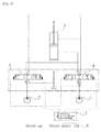
- A hydraulic circuit for a construction machine having a floating function in accordance with the prior art is disclosed in
Korean Patent Registration No. 10-0621977 Fig. 1 , the hydraulic circuit for a construction machine having a floating function includes: - at least two
hydraulic pumps 1 and 2; - a
hydraulic cylinder 3 that is driven by hydraulic fluids supplied from thehydraulic pumps 1 and 2; - a boom
driving control valve 4 that is installed in a flow path between any one 1 of the hydraulic pumps I and 2 and thehydraulic cylinder 3 and is configured to be shifted to control a start, a stop, and a direction change of thehydraulic cylinder 3; - a boom
confluence control valve 5 that is installed in a flow path between the other 2 of thehydraulic pumps 1 and 2 and thehydraulic cylinder 3 and is configured to be shifted to allow the hydraulic fluid discharged from thehydraulic pump 2 to join the hydraulic fluid that has passed through the boomdriving control valve 4 to cause the joined hydraulic fluids to be supplied to a large chamber of thehydraulic cylinder 3, or to allow hydraulic fluids of the large chamber and a small chamber of thehydraulic cylinder 3 to join together so as to be supplied to ahydraulic tank 6 to shift the boomconfluence control valve 5 to a floating state; and - a
control valve 7 that is installed in a flow path between a manipulation lever (not shown), and the boomdriving control valve 4 and the boomconfluence control valve 5, and configured to be shifted to supply the hydraulic fluid discharged from the hydraulic pump 1 to the small chamber of thehydraulic cylinder 3 through application of the boom-down pilot pressure to the boomdriving control valve 4, or to shift the boomconfluence control valve 5 to an on state to cause the boomconfluence control valve 5 be shifted to the floating state through application of the boom-down pilot pressure to the boomconfluence control valve 5. - When a spool of the
control valve 7 is shifted to the left on the drawing sheet in response to an electrical signal applied thereto, a boom-down pilot pressure is applied to one end of the boomconfluence control valve 5 via thecontrol valve 7 by the manipulation of the manipulation lever to cause a spool of the boomconfluence control valve 5 to be shifted to the left on the drawing sheet. - In other words, the boom
confluence control valve 5 is shifted to the floating state. The boomconfluence control valve 5 is shifted to allow the hydraulic fluids of the large chamber and the small chamber of thehydraulic cylinder 3 to join together in the boomconfluence control valve 5 so as to be returned to thehydraulic fluid tank 6 so that the boomconfluence control valve 5 is shifted to the floating state. - As described above, when the boom
confluence control valve 5 is shifted to the floating state by the shift of thecontrol valve 7, the boom-down pilot pressure is not applied to the boomdriving control valve 4, and thus the hydraulic fluid from the hydraulic pump 1 is not supplied to the small chamber of thehydraulic cylinder 3. As a result, the boom cannot descend in a state where thecontrol valve 7 is switched to the on state, thus making it impossible to perform the jack-up operation. - Accordingly, the present invention has been made to solve the aforementioned problems occurring in the prior art, and it is an object of the present invention to provide a hydraulic circuit for a construction machine having a floating function and a method for controlling a floating function, in which the floating function can be inactivated during the boom-up or jack-up operation, and the floating function can be activated during the boom-down operation,.
- To achieve the above object, in accordance with an embodiment of the present invention, there is provided a hydraulic circuit for a construction machine having a floating function, including:
- at least two hydraulic pumps;
- a hydraulic cylinder driven by hydraulic fluids supplied from the hydraulic pumps;
- a boom driving control valve installed in a flow path between any one of the hydraulic pumps and the hydraulic cylinder and configured to be shifted to control a start, a stop, and a direction change of the hydraulic cylinder;
- a boom confluence control valve installed in a flow path between the other of the hydraulic pumps and the hydraulic cylinder and configured to be shifted to allow the hydraulic fluids discharged from the hydraulic pumps to join together so as to be supplied to a large chamber of the hydraulic cylinder or to allow hydraulic fluids of the large chamber and a small chamber of the hydraulic cylinder to join together so as to be supplied to a hydraulic tank;
- a manipulation lever configured to output a manipulation signal corresponding to a manipulation amount;
- a first pressure sensor configured to measure a pressure of the hydraulic fluid on the large chamber of the
hydraulic cylinder 3; - a second pressure sensor configured to measure a boom-down pilot pressure that is applied to the other end of the boom driving control valve;
- a control valve installed in a flow path between the manipulation lever, and the boom driving control valve and the boom confluence control valve, and configured to be shifted in response to the application of electrical signals that correspond to the pressure values detected by the first and second pressure sensors to shift the boom confluence control valve to a floating state through application of the boom-down pilot pressure to the boom confluence control valve, or to supply the hydraulic fluid of the one of the hydraulic pumps to the small chamber of the hydraulic cylinder by the shift of the boom driving control valve through application of the boom-down pilot pressure to the boom driving control valve.
- To achieve the above object, in accordance with an embodiment of the present invention, there is provided a method for controlling a floating function for a construction machine including at least two hydraulic pumps, a hydraulic cylinder driven by hydraulic fluids supplied from the hydraulic pumps, a boom driving control valve installed in a flow path between any one of the hydraulic pumps and the hydraulic cylinder, a boom confluence control valve installed in a flow path between the other of the hydraulic pumps and the hydraulic cylinder, a manipulation lever, a first pressure sensor configured to measure a pressure of the hydraulic fluid on a large chamber of the hydraulic cylinder, a second pressure sensor configured to measure a boom-down pilot pressure that is applied to the other end of the boom driving control valve, and a control valve installed in a flow path between the manipulation lever, and the boom driving control valve and the boom confluence control valve, the method including:
- a step of determining whether a boom floating function switch is operated to be turned on;
- a step of, if the boom floating function switch is operated to be turned on, shifting the control valve to an on state in response to the application of an electrical signal to the control valve to cause the boom confluence control valve to be shifted to a floating state through application of the boom-down pilot pressure to the boom confluence control valve;
- a step of measuring the hydraulic fluid pressure of the large chamber of the hydraulic cylinder through the first pressure sensor, and measuring the boom-down pilot pressure that is applied to the other end of the boom driving control valve through the second pressure sensor; and
- a step of shifting the control valve to an off state if the boom-down pilot pressure is higher than or equal to a predetermined pressure based on a detection signal of the second pressure sensor, and the hydraulic fluid pressure of the large chamber of the hydraulic cylinder is lower than or equal to a predetermined pressure based on a detection signal of the first pressure sensor.
- In accordance with a preferred embodiment of the present invention, the control valve may be a solenoid valve configured to be shifted to an initial state where the hydraulic fluid of the one of the hydraulic pumps is supplied to the small chamber of the hydraulic cylinder through the application of the boom-down pilot pressure to the boom driving control valve, or to an on state where the boom confluence control valve is shifted to the floating state through the application of the boom-down pilot pressure to the boom confluence control valve.
- Further, in accordance with a preferred embodiment of the present invention, the control valve may be shifted to an off state if the boom-down pilot pressure is higher than or equal to a predetermined pressure based on a detection signal of the second pressure sensor, and the hydraulic fluid pressure of the large chamber of the hydraulic cylinder is lower than or equal to a predetermined pressure based on a detection signal of the first pressure sensor.
- To achieve the above object, in accordance with another embodiment of the present invention, there is provided a hydraulic circuit for a construction machine having a floating function, including:
- at least two hydraulic pumps;
- a hydraulic cylinder driven by hydraulic fluids supplied from the hydraulic pumps;
- a boom driving control valve installed in a flow path between any one of the hydraulic pumps and the hydraulic cylinder and configured to be shifted to control a start, a stop, and a direction change of the hydraulic cylinder;
- a boom confluence control valve installed in a flow path between the other of the hydraulic pumps and the hydraulic cylinder and configured to be shifted to allow the hydraulic fluids discharged from the hydraulic pumps to join together so as to be supplied to a large chamber of the hydraulic cylinder or to allow hydraulic fluids of the large chamber and a small chamber of the hydraulic cylinder to join together so as to be supplied to a hydraulic tank;
- a manipulation lever configured to output a manipulation signal corresponding to a manipulation amount;
- a first pressure sensor configured to measure a pressure of the hydraulic fluid on the large chamber of the hydraulic cylinder;
- a second pressure sensor configured to measure a boom-down pilot pressure that is applied to the other end of the boom driving control valve;
- a first electronic proportional control valve installed in a flow path between the manipulation lever and the boom confluence control valve and configured to shift the boom confluence control valve to a floating mode by generating the boom-down pilot pressure in proportion to an electrical signal applied thereto and applying the generated boom-down pilot pressure to the boom confluence control valve;
- a second electronic proportional control valve installed in a flow path between the manipulation lever and the boom driving control valve and configured to supply the hydraulic fluid of the one of the hydraulic pumps to the small chamber of the hydraulic cylinder by generating the boom-down pilot pressure in proportion to the electrical signal applied thereto and applying the generated boom-down pilot pressure to the boom driving control valve; and
- a controller configured to receive an input of the pressure values detected by the first and second pressure sensors, calculate the electrical signal corresponding to the pressure value detected by the second pressure sensor, and apply the calculated electrical signal to the first and second electronic proportional control valves.
- To achieve the above object, in accordance with another embodiment of the present invention, there is provided a method for controlling a floating function for a construction machine including at least two hydraulic pumps, a hydraulic cylinder driven by hydraulic fluids supplied from the hydraulic pumps, a boom driving control valve installed in a flow path between any one of the hydraulic pumps and the hydraulic cylinder, a boom confluence control valve installed in a flow path between the other of the hydraulic pumps and the hydraulic cylinder, a manipulation lever, a first pressure sensor configured to measure a pressure of the hydraulic fluid on a large chamber of the hydraulic cylinder, a second pressure sensor configured to measure a boom-down pilot pressure that is applied to the other end of the boom driving control valve, a first electronic proportional control valve installed in a flow path between the manipulation lever and the boom confluence control valve, and a second electronic proportional control valve installed in a flow path between the manipulation lever and the boom driving control valve, the method including:
- a step of determining whether a boom floating function switch is operated to be turned on;
- a step of measuring the hydraulic fluid pressure of the large chamber of the hydraulic cylinder through the first pressure sensor, and measuring the boom-down pilot pressure that is applied to the boom driving control valve through the second pressure sensor;
- a step of supplying the hydraulic fluid of the one of the hydraulic pumps to a small chamber of the hydraulic cylinder by applying the boom-down pilot pressure, which is generated in proportion to an electrical signal corresponding to a pressure detection value of the second pressure sensor, to the boom driving control valve if the boom-down pilot pressure is higher than a predetermined pressure based on a detection signal of the second pressure sensor, and the hydraulic fluid pressure of the large chamber of the hydraulic cylinder is lower than a predetermined pressure based on a detection signal of the first pressure sensor; and
- a step of shifting the boom confluence control valve to a floating mode by applying the boom-down pilot pressure, which is generated in proportion to the electrical signal corresponding to the pressure detection value of the second pressure sensor, to the boom confluence control valve if the boom-down pilot pressure is lower than the predetermined pressure based on the detection signal of the second pressure sensor, and the hydraulic fluid pressure of the large chamber of the hydraulic cylinder is higher than the predetermined pressure based on the detection signal of the first pressure sensor.
- The hydraulic circuit for a construction machine having a floating function and the method for controlling the floating function in accordance with the present invention as constructed above have the following advantages.
- In the case where the leveling and grading work is performed by using an excavator or the boom descends by its own weight, the hydraulic fluid discharged from the hydraulic pump is supplied to a hydraulic actuator other than a boom cylinder, thereby saving the hydraulic energy. In addition, in the floating mode, the hydraulic fluid discharged from the hydraulic pump is selectively supplied to a small chamber of the boom cylinder to perform the jack-up operation, thereby improving the workability.
- The above objects, other features and advantages of the present invention will become more apparent by describing the preferred embodiments thereof with reference to the accompanying drawings, in which:
-
Fig. 1 is a diagram showing a hydraulic circuit for a construction machine having a floating function in accordance with the prior art; -
Fig. 2 is a diagram showing a hydraulic circuit for a construction machine having a floating function in accordance with an embodiment of the present invention; -
Fig. 3 is a flow chart showing a control algorithm of a control valve in a hydraulic circuit for a construction machine having a floating function in accordance with an embodiment of the present invention; -
Fig. 4 is a diagram showing a hydraulic circuit for a construction machine having a floating function in accordance with another embodiment of the present invention; and -
Fig. 5 is a flow chart showing a control algorithm of a control valve in a hydraulic circuit for a construction machine having a floating function in accordance with another embodiment of the present invention. -
- 1, 2: hydraulic pump
- 3: hydraulic cylinder
- 4: boom driving control valve
- 5: boom confluence control valve]
- 6: hydraulic fluid tank
- 7: control valve
- 8: first pressure sensor
- 9: second pressure sensor
- 11: controller
- Hereinafter, a hydraulic circuit for a construction machine having a floating function and a method for controlling a floating function for a construction machine in accordance with a preferred embodiment of the present invention will be described in detail with reference to the accompanying drawings. The matters defined in the description, such as the detailed construction and elements, are nothing but specific details provided to assist those of ordinary skill in the art in a comprehensive understanding of the invention, and the present invention is not limited to the embodiments disclosed hereinafter.
- In order to definitely describe the present invention, a portion having no relevant to the description will be omitted, and through the specification, like elements are designated by like reference numerals.
- In the specification and the claims, when a portion includes an element, it is meant to include other elements, but not exclude the other elements unless otherwise specifically stated herein.
- Prior to the following detailed description, the terms or words used in the specification and the claims of the present invention should not be construed as being typical or dictionary meanings, but should be construed as meanings and concepts conforming to the technical spirit of the present invention on the basis of the principle that an inventor can properly define the concepts of the terms in order to describe his or her invention in the best way.
- Hereinafter, a hydraulic circuit for a construction machine having a floating function in accordance with a preferred embodiment of the present invention will be described in detail with reference to the accompanying drawings.
-
Fig. 2 is a diagram showing a hydraulic circuit for a construction machine having a floating function in accordance with an embodiment of the present invention,Fig. 3 is a flow chart showing a control algorithm of a control valve in a hydraulic circuit for a construction machine having a floating function in accordance with an embodiment of the present invention,Fig. 4 is a diagram showing a hydraulic circuit for a construction machine having a floating function in accordance with another embodiment of the present invention, andFig. 5 is a flow chart showing a control algorithm of a control valve in a hydraulic circuit for a construction machine having a floating function in accordance with another embodiment of the present invention. - Referring to
Figs. 2 and3 , a hydraulic circuit for a construction machine having a floating function in accordance with an embodiment of the present invention includes: - at least two
hydraulic pumps 1 and 2; - a
hydraulic cylinder 3 that is driven by hydraulic fluids supplied from thehydraulic pumps 1 and 2; - a boom driving
control valve 4 that is installed in a flow path between any one 1 of thehydraulic pumps 1 and 2 and thehydraulic cylinder 3 and is configured to be shifted to control a start, a stop, and a direction change of thehydraulic cylinder 3; - a boom
confluence control valve 5 that is installed in a flow path between the other 2 of thehydraulic pumps 1 and 2 and thehydraulic cylinder 3 and is configured to be shifted to allow the hydraulic fluids discharged from thehydraulic pumps 1 and 2 to join together so as to be supplied to a large chamber of thehydraulic cylinder 3 or to allow hydraulic fluids of the large chamber and a small chamber of thehydraulic cylinder 3 to join together so as to be supplied to ahydraulic tank 6; - a manipulation lever (RCV) that is configured to output a manipulation signal corresponding to a manipulation amount;
- a
first pressure sensor 8 that is configured to detect a pressure of the hydraulic fluid on the large chamber of thehydraulic cylinder 3; - a
second pressure sensor 9 that is configured to detect a boom-down pilot pressure that is applied to the other end of the boom drivingcontrol valve 4; and - a
control valve 7 that is installed in a flow path between the manipulation lever and the boom drivingcontrol valve 4 and the boomconfluence control valve 5, and is configured to be shifted in response to the application of electrical signals that correspond to the pressure values detected by the first andsecond pressure sensors confluence control valve 5 to a floating state through application of the boom-down pilot pressure to the boomconfluence control valve 5, or to supply the hydraulic fluid of the one 1 of thehydraulic pumps 1 and 2 to the small chamber of thehydraulic cylinder 3 by the shift of the boom drivingcontrol valve 4 through application of the boom-down pilot pressure to the boom drivingcontrol valve 4. - The
control valve 7 is a solenoid valve configured to be shifted to an initial state where the hydraulic fluid of the one 1 of thehydraulic pumps 1 and 2 is supplied to the small chamber of thehydraulic cylinder 3 through the application of the boom-down pilot pressure to the boom drivingcontrol valve 4, or to an ON state where the boomconfluence control valve 5 is shifted to the floating state through the application of the boom-down pilot pressure to the boomconfluence control valve 5. - The
control valve 7 is shifted to an off state if the boom-down pilot pressure is higher than or equal to a predetermined pressure based on a detection signal of thesecond pressure sensor 9, and the hydraulic fluid pressure of the large chamber of thehydraulic cylinder 3 is lower than or equal to a predetermined pressure based on a detection signal of thefirst pressure sensor 8. - Referring to
Figs. 2 and3 , in accordance with an embodiment of the present invention, in a method for controlling a floating function for a construction machine including at least twohydraulic pumps 1 and 2, ahydraulic cylinder 3 driven by hydraulic fluids supplied from thehydraulic pumps 1 and 2, a boom drivingcontrol valve 4 installed in a flow path between any one 1 of thehydraulic pumps 1 and 2 and thehydraulic cylinder 3, a boomconfluence control valve 5 installed in a flow path between the other 2 of thehydraulic pumps 1 and 2 and thehydraulic cylinder 3, a manipulation lever (RCV), afirst pressure sensor 8 configured to measure a pressure of the hydraulic fluid on a large chamber of thehydraulic cylinder 3, asecond pressure sensor 9 configured to measure a boom-down pilot pressure that is applied to the other end of the boom drivingcontrol valve 4, and acontrol valve 7 installed in a flow path between the manipulation lever, and the boom drivingcontrol valve 4 and the boomconfluence control valve 5, the method includes: - a step S10 of determining whether a boom floating function switch (not shown) is operated to be turned on;
- a step S20 of, if the boom floating function switch is operated to be turned on, shifting the
control valve 7 to an on state in response to the application of an electrical signal to thecontrol valve 7 to cause the boom confluence control valve to be shifted to a floating state through application of the boom-down pilot pressure to the boomconfluence control valve 5; - a step S30 of measuring the hydraulic fluid pressure of the large chamber of the
hydraulic cylinder 3 through thefirst pressure sensor 8, and measuring the boom-down pilot pressure that is applied to the other end of the boom drivingcontrol valve 4 through thesecond pressure sensor 9; - a step S40 of determining whether the boom-down pilot pressure is higher than or equal to a predetermined pressure based on a detection signal of the
second pressure sensor 9; - a step S50 of determining whether the hydraulic fluid pressure of the large chamber of the
hydraulic cylinder 3 is lower than or equal to a predetermined pressure based on a detection signal of thefirst pressure sensor 8; and - a step S60 of shifting the
control valve 7 to an off state if the boom-down pilot pressure is higher than or equal to the predetermined pressure based on a detection signal of thesecond pressure sensor 9, and the hydraulic fluid pressure of the large chamber of thehydraulic cylinder 3 is lower than or equal to the predetermined pressure based on a detection signal of thefirst pressure sensor 8. - A
non-explained reference numeral 11 denotes a controller that receives an input of a detection signal from the first andsecond pressure sensors control valve 7 to shift thecontrol valve 7. - By virtue of the configuration as described above, the boom-down operation in which a boom descends in a floating state to perform the leveling and grading work using an excavator will be described hereinafter with reference to
Figs. 2 and3 . - A spool of the
control valve 7 is shifted to the left on the drawing sheet in response to an electrical signal applied thereto from thecontroller 11 to cause a boom-down pilot pressure to be applied to a right end of the boomconfluence control valve 5 via thecontrol valve 7. Resultantly, the hydraulic fluids from thehydraulic pumps 1 and 2 join together so as to be returned to thehydraulic fluid tank 6, and the hydraulic fluids of the small chamber and the larger chamber of thehydraulic cylinder 3 join together at aninternal passage 5c of the boomconfluence control valve 5 so as to be returned to thehydraulic fluid tank 6. - Thus, in the case where the leveling and grading work is performed by using an excavator, the boom
confluence control valve 5 is shifted to the floating stat so that the leveling and grading work can be performed while the boom descending by the work apparatus's own weight to avoid the use of the hydraulic fluids from thehydraulic pumps 1 and 2. As a result, the hydraulic fluids from thehydraulic pumps 1 and 2 are supplied to another hydraulic actuator (e.g., a swing motor or the like) except the hydraulic cylinder 3 (e.g., a boom cylinder) so that the hydraulic energy can be saved. - In the meantime, the operation in which the hydraulic fluids from the
hydraulic pumps 1 and 2 join together so as to be supplied the large chamber of thehydraulic cylinder 3 will be described hereinafter with reference withFig. 2 . - A boom-up pilot pressure is applied to left ends of the boom
confluence control valve 5 and the boom drivingcontrol valve 4 by the manipulation of the manipulation lever to shift the spools of the boomconfluence control valve 5 and the boom drivingcontrol valve 4 to the right. Resultantly, the hydraulic fluid from the hydraulic pump 1 is supplied to the large chamber of thehydraulic cylinder 3 via the shifted boom drivingcontrol valve 4, and the hydraulic fluid from thehydraulic pump 2 is supplied to the large chamber of thehydraulic cylinder 3 via the shifted confluence drivingcontrol valve 5. - In other words, the hydraulic fluid from the
hydraulic pump 2 joins the hydraulic fluid from the hydraulic pump 1, which has passed through the boom drivingcontrol valve 4, and is supplied to the larger chamber of thehydraulic cylinder 3 so that the boom-up operation can be performed. - In the meantime, the operation in which the boom descends to perform a general work using the excavator will be described hereinafter with reference with
Fig. 2 . - The boom-down pilot pressure is applied to a right end of the boom driving
control valve 4 via thecontrol valve 7 by the manipulation of the manipulation lever to shift the spool of the boom drivingcontrol valve 4 to the left. Resultantly, the hydraulic fluid from the hydraulic pump 1 is supplied to the small chamber of thehydraulic cylinder 3 via the shifted boom drivingcontrol valve 4, and the hydraulic fluid discharged from the large chamber of thehydraulic cylinder 3 is returned to thehydraulic fluid tank 6 via the shifted boom drivingcontrol valve 4. - Thus, the
hydraulic cylinder 3 can be driven in a stretchable manner to perform the boom-down operation. - In the meantime, the operation in which the boom descends in a state where the boom
confluence control valve 5 is shifted to the floating mode with reference withFigs. 2 and3 . - In step S10, the
controller 11 determines whether a boom floating function switch (not shown) is operated to be turned on. If it is determined that boom floating function switch is operated to be turned on, the program proceeds to step S20, and it is determined that boom floating function switch is operated to be turned off, the program is terminated. - In step S20, if the
control valve 7 is shifted to an on state in response to the application of an electrical signal thereto from thecontroller 11, the boom-down pilot pressure is applied to the boomconfluence control valve 5 to cause the boomconfluence control valve 5 to be shifted to the floating state. - In step S30, the hydraulic fluid pressure of the large chamber of the
hydraulic cylinder 3 is measured by thefirst pressure sensor 8 and the boom-down pilot pressure applied to the boom drivingcontrol valve 4 is measured by thesecond pressure sensor 9, and the detection signals of the first andsecond pressure sensors controller 11. - In step S40, the boom-down pilot pressure detected by the
second pressure sensor 9 is compared with a predetermined pressure Ps1. If it is determined that the detected boom-down pilot pressure is higher than or equal to the predetermined pressure Ps1, the program proceeds to step S50, and if it is determined that the boom-down pilot pressure is lower than the predetermined pressure Ps1, the program is terminated. - In step S50, the hydraulic fluid pressure of the large chamber of the
hydraulic cylinder 3, which is detected by thefirst pressure sensor 8, is compared with a predetermined pressure Ps2. If it is determined that the detected hydraulic fluid pressure of the large chamber of thehydraulic cylinder 3 is lower than or equal to the predetermined pressure Ps2, the program proceeds to step S60, and if it is determined that the detected hydraulic fluid pressure of the large chamber of thehydraulic cylinder 3 is higher than the predetermined pressure Ps2, the program is terminated. - In step S60, if it is determined that the boom-down pilot pressure detected by the
second pressure sensor 9 is higher than or equal to the predetermined pressure Ps1 and the hydraulic fluid pressure of the large chamber of thehydraulic cylinder 3, which is detected by thefirst pressure sensor 8 is lower than or equal to the predetermined pressure Ps2, thecontrol valve 7 is shifted to the off state in response to an electrical signal applied thereto from thecontroller 11. - As described above, in a state where the
control valve 7 is shifted to the on state in response to the electrical signal applied thereto from thecontroller 11 to cause the boomconfluence control valve 5 to be shifted to the floating state, if the boom-down pilot pressure detected by thesecond pressure sensor 9 is higher than or equal to the predetermined pressure Ps1 (i.e., boom-down pilot pressure ≥ Ps1) and the hydraulic fluid pressure of the large chamber of thehydraulic cylinder 3, which is detected by thefirst pressure sensor 8 is lower than or equal to the predetermined pressure Ps2 (i.e., hydraulic fluid pressure of the large chamber of thehydraulic cylinder 3 ≤ Ps2), thecontrol valve 7 is shifted to the off state in response to an electrical signal applied thereto from the controller 11 (seeFig. 2 ). - Thus, the boom-down pilot pressure is applied to the right end of the boom driving
control valve 4 via thecontrol valve 7 by the manipulation of the manipulation lever to shift the spool of the boom drivingcontrol valve 4 to the left on the drawing sheet. Resultantly, the hydraulic fluid from the hydraulic pump 1 is supplied to the small chamber of thehydraulic cylinder 3 via the shifted boom drivingcontrol valve 4, and the hydraulic fluid discharged from the large chamber of thehydraulic cylinder 3 is returned to thehydraulic fluid tank 6 via the shifted boom drivingcontrol valve 4. - Accordingly, during the leveling and grading work using the excavator, if the boom-down pilot pressure detected by the
second pressure sensor 9 is higher than or equal to the predetermined pressure and the hydraulic fluid pressure of the large chamber of thehydraulic cylinder 3, which is detected by thefirst pressure sensor 8 is lower than or equal to the predetermined pressure, thecontrol valve 7 is shifted to the off state in response to an electrical signal applied thereto from thecontroller 11. As a result, the boom-down pilot pressure is applied to the boom drivingcontrol valve 4 to cause the hydraulic fluid from the hydraulic pump 1 to be supplied to the small chamber of thehydraulic cylinder 3 so that the boom can descend to perform the jack-up operation. - Referring to
Figs. 4 and5 , a hydraulic circuit for a construction machine having a floating function in accordance with another embodiment of the present invention includes: - at least two
hydraulic pumps 1 and 2; - a
hydraulic cylinder 3 that is driven by hydraulic fluids supplied from thehydraulic pumps 1 and 2; - a boom driving
control valve 4 that is installed in a flow path between any one 1 of thehydraulic pumps 1 and 2 and thehydraulic cylinder 3 and is configured to be shifted to control a start, a stop, and a direction change of thehydraulic cylinder 3; - a boom
confluence control valve 5 that is installed in a flow path between the other 2 of thehydraulic pumps 1 and 2 and thehydraulic cylinder 3 and is configured to be shifted to allow the hydraulic fluids discharged from thehydraulic pumps 1 and 2 to join together so as to be supplied to a large chamber of thehydraulic cylinder 3 or to allow hydraulic fluids of the large chamber and a small chamber of thehydraulic cylinder 3 to join together so as to be supplied to ahydraulic tank 6; - a manipulation lever (not shown) that is configured to output a manipulation signal corresponding to a manipulation amount;
- a
first pressure sensor 8 that is configured to detect a pressure of the hydraulic fluid on the large chamber of thehydraulic cylinder 3; - a
second pressure sensor 9 that is configured to detect a boom-down pilot pressure that is applied to the other end of the boom drivingcontrol valve 4; - a first electronic proportional control valve 12 that is installed in a flow path between the manipulation lever and the boom
confluence control valve 5 and is configured to shift the boomconfluence control valve 5 to a floating mode by generating the boom-down pilot pressure in proportion to an electrical signal applied thereto and applying the generated boom-down pilot pressure to the boomconfluence control valve 5; - a second electronic
proportional control valve 13 that is installed in a flow path between the manipulation lever and the boom drivingcontrol valve 4 and is configured to supply the hydraulic fluid of the one 1 of thehydraulic pumps 1 and 2 to the small chamber of thehydraulic cylinder 3 by generating the boom-down pilot pressure in proportion to the electrical signal applied thereto and applying the generated boom-down pilot pressure to the boom drivingcontrol valve 4; and - a
controller 11 that is configured to receive an input of the pressure values detected by the first andsecond pressure sensors second pressure sensor 9, and apply the calculated electrical signal to the first and second electronicproportional control valves 12 and 13. - Referring to
Figs. 4 and5 , in accordance with another embodiment of the present invention, in a method for controlling a floating function for a construction machine including at least twohydraulic pumps 1 and 2, ahydraulic cylinder 3 driven by hydraulic fluids supplied from thehydraulic pumps 1 and 2, a boom drivingcontrol valve 4 installed in a flow path between any one 1 of thehydraulic pumps 1 and 2 and thehydraulic cylinder 3, a boomconfluence control valve 5 installed in a flow path between the other 2 of thehydraulic pumps 1 and 2 and thehydraulic cylinder 3, a manipulation lever (not shown), afirst pressure sensor 8 configured to measure a pressure of the hydraulic fluid on a large chamber of thehydraulic cylinder 3, asecond pressure sensor 9 configured to measure a boom-down pilot pressure that is applied to the other end of the boom drivingcontrol valve 4, a first electronic proportional control valve 12 installed in a flow path between the manipulation lever and the boomconfluence control valve 5; and a second electronicproportional control valve 13 installed in a flow path between the manipulation lever and the boom drivingcontrol valve 4, the method includes: - a step (S100) of determining whether a boom floating function switch is operated to be turned on;
- a step (S200) of measuring the hydraulic fluid pressure of the large chamber of the
hydraulic cylinder 3 through thefirst pressure sensor 8, and measuring the boom-down pilot pressure that is applied to the boom drivingcontrol valve 4 through thesecond pressure sensor 9; - a step (S300) of determining whether the boom-down pilot pressure is higher than or equal to a predetermined pressure Ps1 based on a detection signal of the
second pressure sensor 9; - a step (S400) of determining whether the hydraulic fluid pressure of the large chamber of the
hydraulic cylinder 3 is lower than a predetermined pressure Ps2 based on a detection signal of thefirst pressure sensor 8; - a step (S500) of supplying the hydraulic fluid of the one 1 of the
hydraulic pumps 1 and 2 to a small chamber of thehydraulic cylinder 3 by applying the boom-down pilot pressure, which is generated in proportion to an electrical signal corresponding to a pressure detection value of thesecond pressure sensor 9, to the boom drivingcontrol valve 4 if the boom-down pilot pressure is higher than or equal to the predetermined pressure Ps1 (i.e., the boom-down pilot pressure ≥ Ps1) based on a detection signal of thesecond pressure sensor 9, and the hydraulic fluid pressure of the large chamber of thehydraulic cylinder 3 is lower than or equal to the predetermined pressure Ps2 (i.e., the hydraulic fluid pressure of the large chamber ≤ Ps2) based on a detection signal of thefirst pressure sensor 8; and - a step (S600) of shifting the boom
confluence control valve 5 to a floating mode by applying the boom-down pilot pressure, which is generated in proportion to the electrical signal corresponding to the pressure detection value of thesecond pressure sensor 9, to the boomconfluence control valve 5 if the boom-down pilot pressure is lower than the predetermined pressure Ps1 based on the detection signal of thesecond pressure sensor 9, and the hydraulic fluid pressure of the large chamber of thehydraulic cylinder 3 is higher than the predetermined pressure Ps2 based on the detection signal of thefirst pressure sensor 8. - In this case, a configuration of the hydraulic circuit for a construction machine having a floating function in accordance with another embodiment of the present invention is the same as that of the hydraulic circuit for a construction machine having a floating function in accordance with an embodiment of the present invention, except the first electronic proportional control valve 12 installed in a flow path between the manipulation lever and the boom
confluence control valve 5, the second electronicproportional control valve 13 installed in a flow path between the manipulation lever and the boom drivingcontrol valve 4, and the controller configured to receive an input of the pressure values detected by the first andsecond pressure sensors second pressure sensor 9, and apply the calculated electrical signal to the first and secondelectronic_proportional control valves 12 and 13. Thus, the detailed description of the same configuration and operation thereof will be omitted to avoid redundancy, and the same hydraulic parts are denoted by the same reference numerals. - By virtue of the configuration as described above, the boom-down operation in which a boom descends in a floating state to perform the leveling and grading work using an excavator will be described hereinafter with reference to
Figs. 2 and3 . - In step S100, the
controller 11 determines whether a boom floating function switch is operated to be turned on. If it is determined that boom floating function switch is operated to be turned on, the program proceeds to step S200, and it is determined that boom floating function switch is operated to be turned off, the program is terminated. - In step S200, the hydraulic fluid pressure of the large chamber of the
hydraulic cylinder 3 is measured by thefirst pressure sensor 8 and the boom-down pilot pressure applied to the boom drivingcontrol valve 4 is measured by thesecond pressure sensor 9. In this case, the detection signals measured by the first andsecond pressure sensors controller 11. - In step S300, the boom-down pilot pressure detected by the
second pressure sensor 9 is compared with a predetermined pressure Ps1. If it is determined that the detected boom-down pilot pressure is higher than or equal to the predetermined pressure Ps1, the program proceeds to step S400, and if it is determined that the boom-down pilot pressure is lower than the predetermined pressure Ps1, the program proceeds to step S600. - In step S400, the hydraulic fluid pressure of the large chamber of the
hydraulic cylinder 3, which is detected by thefirst pressure sensor 8, is compared with a predetermined pressure Ps2. If it is determined that the detected hydraulic fluid pressure of the large chamber of thehydraulic cylinder 3 is lower than or equal to the predetermined pressure Ps2, the program proceeds to step S500, and if it is determined that the detected hydraulic fluid pressure of the large chamber of thehydraulic cylinder 3 is higher than the predetermined pressure Ps2, the program proceeds to step S600. - In step S500, if it is determined that the boom-down pilot pressure detected by the
second pressure sensor 9 is higher than or equal to the predetermined pressure Ps1 and the hydraulic fluid pressure of the large chamber of thehydraulic cylinder 3, which is detected by thefirst pressure sensor 8 is lower than or equal to the predetermined pressure Ps2, thecontroller 11 applies an electrical signal calculated in proportion to the boom-down pilot pressure measured by thesecond pressure sensor 9 to the second electronicproportional control valve 13. - The second electronic
proportional control valve 13 generates a pilot pressure corresponding to the electrical signal applied thereto and applies the generated pilot pressure to the right end of the boom drivingcontrol valve 4. Thus, the spool of the boom drivingcontrol valve 4 is shifted to the left on the drawing sheet. Resultantly, the hydraulic fluid discharged from the hydraulic pump 1 is supplied to the small chamber of thehydraulic cylinder 3 via the shifted boom drivingcontrol valve 4, and the hydraulic fluid discharged from the large chamber of thehydraulic cylinder 3 is returned to thehydraulic fluid tank 6 via the shifted boom drivingcontrol valve 4. Thus, thehydraulic cylinder 3 can be driven in a stretchable manner to descend the boom. - In other words, during the leveling and grading work using the excavator, if the boom-down pilot pressure detected by the
second pressure sensor 9 is higher than or equal to the predetermined pressure and the hydraulic fluid pressure of the large chamber of thehydraulic cylinder 3, which is detected by thefirst pressure sensor 8 is lower than or equal to the predetermined pressure, the boom drivingcontrol valve 4 is shifted to cause the hydraulic fluid from the hydraulic pump 1 to be supplied to the small chamber of thehydraulic cylinder 3 so that the boom can descend to perform the jack-up operation. - In step S600, if it is determined that the boom-down pilot pressure is lower than the predetermined pressure Ps1 based on the detection signal of the
second pressure sensor 9 and the hydraulic fluid pressure of the large chamber of thehydraulic cylinder 3 is higher than the predetermined pressure Ps2 based on the detection signal of thefirst pressure sensor 8, thecontroller 11 applies an electrical signal calculated in proportion to the boom-down pilot pressure measured by thesecond pressure sensor 9 to the first electronic proportional control valve 12. - The first electronic proportional control valve 12 generating the boom-down pilot pressure in proportion to the electrical signal applied thereto and applying the generated boom-down pilot pressure to the right end of the boom
confluence control valve 5. In other words, the spool of the boomconfluence control valve 5 is shifted to the right on the drawing sheet to cause the hydraulic fluids of the large chamber and the small chamber of thehydraulic cylinder 3 to join together so as to be supplied to thehydraulic fluid tank 6 so that the boomconfluence control valve 5 can be shifted to the floating mode. In this case, the hydraulic fluid discharged from thehydraulic pump 2 is returned to thehydraulic fluid tank 6 via the boomconfluence control valve 5. - In accordance with the hydraulic circuit for a construction machine having a floating function and the method for controlling the floating function of the present invention as constructed above, in the case where the leveling and grading work is performed by using an excavator or the boom descends by its own weight, the hydraulic fluid discharged from the hydraulic pump is supplied to a hydraulic actuator other than a boom cylinder, thereby saving the hydraulic energy. In addition, in the floating mode, the hydraulic fluid discharged from the hydraulic pump is selectively supplied to a small chamber of the boom cylinder to perform the jack-up operation, thereby providing convenience to an operator and improving the workability.
- While the present invention has been described in connection with the specific embodiments illustrated in the drawings, they are merely illustrative, and the invention is not limited to these embodiments. It is to be understood that various equivalent modifications and variations of the embodiments can be made by a person having an ordinary skill in the art without departing from the spirit and scope of the present invention. Therefore, the true technical scope of the present invention should not be defined by the above-mentioned embodiments but should be defined by the appended claims and equivalents thereof.
Claims (6)
- A hydraulic circuit for a construction machine having a floating function, comprising:at least two hydraulic pumps;a hydraulic cylinder driven by hydraulic fluids supplied from the hydraulic pumps;a boom driving control valve installed in a flow path between any one of the hydraulic pumps and the hydraulic cylinder and configured to be shifted to control a start, a stop, and a direction change of the hydraulic cylinder;a boom confluence control valve installed in a flow path between the other of the hydraulic pumps and the hydraulic cylinder and configured to be shifted to allow the hydraulic fluids discharged from the hydraulic pumps to join together so as to be supplied to a large chamber of the hydraulic cylinder or to allow hydraulic fluids of the large chamber and a small chamber of the hydraulic cylinder to join together so as to be supplied to a hydraulic tank;a manipulation lever (RCV) configured to output a manipulation signal corresponding to a manipulation amount;a first pressure sensor configured to measure a pressure of the hydraulic fluid on the large chamber of the hydraulic cylinder;a second pressure sensor configured to measure a boom-down pilot pressure that is applied to the other end of the boom driving control valve; anda control valve installed in a flow path between the manipulation lever, and the boom driving control valve and the boom confluence control valve, and configured to be shifted in response to the application of electrical signals that correspond to the pressure values detected by the first and second pressure sensors to shift the boom confluence control valve to a floating state through application of the boom-down pilot pressure to the boom confluence control valve, or to supply the hydraulic fluid of the one of the hydraulic pumps to the small chamber of the hydraulic cylinder by the shift of the boom driving control valve through application of the boom-down pilot pressure to the boom driving control valve.
- A method for controlling a floating function for a construction machine including at least two hydraulic pumps, a hydraulic cylinder driven by hydraulic fluids supplied from the hydraulic pumps, a boom driving control valve installed in a flow path between any one of the hydraulic pumps and the hydraulic cylinder, a boom confluence control valve installed in a flow path between the other of the hydraulic pumps and the hydraulic cylinder, a manipulation lever (RCV), a first pressure sensor configured to measure a pressure of the hydraulic fluid on a large chamber of the hydraulic cylinder, a second pressure sensor configured to measure a boom-down pilot pressure that is applied to the other end of the boom driving control valve, and a control valve installed in a flow path between the manipulation lever, and the boom driving control valve and the boom confluence control valve, the method comprising:a step of determining whether a boom floating function switch is operated to be turned on;a step of, if the boom floating function switch is operated to be turned on, shifting the control valve to an on state in response to the application of an electrical signal to the control valve to cause the boom confluence control valve to be shifted to a floating state through application of the boom-down pilot pressure to the boom confluence control valve 5;a step of measuring the hydraulic fluid pressure of the large chamber of the hydraulic cylinder 3 through the first pressure sensor, and measuring the boom-down pilot pressure that is applied to the other end of the boom driving control valve 4 through the second pressure sensor; anda step of shifting the control valve to an off state if the boom-down pilot pressure is higher than or equal to a predetermined pressure based on a detection signal of the second pressure sensor, and the hydraulic fluid pressure of the large chamber of the hydraulic cylinder is lower than or equal to the predetermined pressure based on a detection signal of the first pressure sensor.
- The hydraulic circuit according to claim 1, wherein the control valve is a solenoid valve configured to be shifted to an initial state where the hydraulic fluid of the one of the hydraulic pumps is supplied to the small chamber of the hydraulic cylinder through the application of the boom-down pilot pressure to the boom driving control valve, or to an on state where the boom confluence control valve is shifted to the floating state through the application of the boom-down pilot pressure to the boom confluence control valve.
- The hydraulic circuit according to claim 1, wherein the control valve is shifted to an off state if the boom-down pilot pressure is higher than or equal to a predetermined pressure based on a detection signal of the second pressure sensor, and the hydraulic fluid pressure of the large chamber of the hydraulic cylinder is lower than or equal to the predetermined pressure based on a detection signal of the first pressure sensor.
- A hydraulic circuit for a construction machine having a floating function, comprising:at least two hydraulic pumps;a hydraulic cylinder driven by hydraulic fluids supplied from the hydraulic pumps;a boom driving control valve installed in a flow path between any one of the hydraulic pumps and the hydraulic cylinder and configured to be shifted to control a start, a stop, and a direction change of the hydraulic cylinder;a boom confluence control valve installed in a flow path between the other of the hydraulic pumps and the hydraulic cylinder and configured to be shifted to allow the hydraulic fluids discharged from the hydraulic pumps to join together so as to be supplied to a large chamber of the hydraulic cylinder or to allow hydraulic fluids of the large chamber and a small chamber of the hydraulic cylinder to join together so as to be supplied to a hydraulic tank;a manipulation lever (RCV) configured to output a manipulation signal corresponding to a manipulation amount;a first pressure sensor configured to measure a pressure of the hydraulic fluid on the large chamber of the hydraulic cylinder;a second pressure sensor configured to measure a boom-down pilot pressure that is applied to the other end of the boom driving control valve;a first electronic proportional control valve installed in a flow path between the manipulation lever and the boom confluence control valve and configured to shift the boom confluence control valve to a floating mode by generating the boom-down pilot pressure in proportion to an electrical signal applied thereto and applying the generated boom-down pilot pressure to the boom confluence control valve;a second electronic proportional control valve installed in a flow path between the manipulation lever and the boom driving control valve and configured to supply the hydraulic fluid of the one of the hydraulic pumps to the small chamber of the hydraulic cylinder by generating the boom-down pilot pressure in proportion to the electrical signal applied thereto and applying the generated boom-down pilot pressure to the boom driving control valve; anda controller configured to receive an input of the pressure values detected by the first and second pressure sensors, calculate the electrical signal corresponding to the pressure value detected by the second pressure sensor, and apply the calculated electrical signal to the first and second electronic proportional control valves.
- A method for controlling a floating function for a construction machine including at least two hydraulic pumps, a hydraulic cylinder driven by hydraulic fluids supplied from the hydraulic pumps, a boom driving control valve installed in a flow path between any one of the hydraulic pumps and the hydraulic cylinder, a boom confluence control valve installed in a flow path between the other of the hydraulic pumps and the hydraulic cylinder, a manipulation lever (RCV), a first pressure sensor configured to measure a pressure of the hydraulic fluid on a large chamber of the hydraulic cylinder, a second pressure sensor configured to measure a boom-down pilot pressure that is applied to the boom driving control valve, a first electronic proportional control valve installed in a flow path between the manipulation lever and the boom confluence control valve, and a second electronic proportional control valve installed in a flow path between the manipulation lever and the boom driving control valve, the method comprising:a step of determining whether a boom floating function switch is operated to be turned on;a step of measuring the hydraulic fluid pressure of the large chamber of the hydraulic cylinder through the first pressure sensor, and measuring the boom-down pilot pressure that is applied to the boom driving control valve through the second pressure sensor;a step of supplying the hydraulic fluid of the one of the hydraulic pumps to a small chamber of the hydraulic cylinder by applying the boom-down pilot pressure, which is generated in proportion to an electrical signal corresponding to a pressure detection value of the second pressure sensor, to the boom driving control valve if the boom-down pilot pressure is higher than or equal to a predetermined pressure based on a detection signal of the second pressure sensor, and the hydraulic fluid pressure of the large chamber of the hydraulic cylinder is lower than or equal to a predetermined pressure based on a detection signal of the first pressure sensor; anda step of shifting the boom confluence control valve to a floating mode by applying the boom-down pilot pressure, which is generated in proportion to the electrical signal corresponding to the pressure detection value of the second pressure sensor, to the boom confluence control valve if the boom-down pilot pressure is lower than the predetermined pressure based on the detection signal of the second pressure sensor, and the hydraulic fluid pressure of the large chamber of the hydraulic cylinder is higher than the predetermined pressure based on the detection signal of the first pressure sensor.
Applications Claiming Priority (2)
| Application Number | Priority Date | Filing Date | Title |
|---|---|---|---|
| PCT/KR2013/005742 WO2014208795A1 (en) | 2013-06-28 | 2013-06-28 | Hydraulic circuit for construction machinery having floating function and method for controlling floating function |
| PCT/KR2013/009788 WO2014208828A1 (en) | 2013-06-28 | 2013-10-31 | Hydraulic circuit for construction machinery having floating function and method for controlling floating function |
Publications (3)
| Publication Number | Publication Date |
|---|---|
| EP3015718A1 true EP3015718A1 (en) | 2016-05-04 |
| EP3015718A4 EP3015718A4 (en) | 2017-02-22 |
| EP3015718B1 EP3015718B1 (en) | 2020-10-14 |
Family
ID=52142112
Family Applications (1)
| Application Number | Title | Priority Date | Filing Date |
|---|---|---|---|
| EP13888326.9A Active EP3015718B1 (en) | 2013-06-28 | 2013-10-31 | Hydraulic circuit for construction machinery having floating function and method for controlling floating function |
Country Status (6)
| Country | Link |
|---|---|
| US (1) | US10094092B2 (en) |
| EP (1) | EP3015718B1 (en) |
| KR (1) | KR20160023710A (en) |
| CN (1) | CN105339679B (en) |
| CA (1) | CA2916061C (en) |
| WO (2) | WO2014208795A1 (en) |
Cited By (2)
| Publication number | Priority date | Publication date | Assignee | Title |
|---|---|---|---|---|
| CN111197603A (en) * | 2020-03-05 | 2020-05-26 | 三一汽车起重机械有限公司 | Divide and shut flow control module, two main pump oil feeding system, hydraulic system and engineering machine tool |
| EP3910115A3 (en) * | 2020-03-24 | 2022-03-09 | J.C. Bamford Excavators Limited | Hydraulic system for a work machine, work machine comprising such a hydraulic system, and method of operating such a hydraulic system |
Families Citing this family (18)
| Publication number | Priority date | Publication date | Assignee | Title |
|---|---|---|---|---|
| US9725882B2 (en) * | 2013-01-24 | 2017-08-08 | Volvo Construction Equipment Ab | Device and method for controlling flow rate in construction machinery |
| WO2016167377A1 (en) * | 2015-04-13 | 2016-10-20 | 볼보 컨스트럭션 이큅먼트 에이비 | Hydraulic apparatus of construction equipment and control method therefor |
| KR102514523B1 (en) * | 2015-12-04 | 2023-03-27 | 현대두산인프라코어 주식회사 | Hydraulic control apparatus and hydraulic control method for construction machine |
| CN106468062B (en) * | 2016-09-22 | 2018-09-11 | 柳州柳工挖掘机有限公司 | Excavator soil-shifting hydraulic system with dozer float function |
| GB2554682B (en) | 2016-10-03 | 2022-01-19 | Bamford Excavators Ltd | Hydraulic systems for construction machinery |
| WO2018173289A1 (en) * | 2017-03-24 | 2018-09-27 | 株式会社日立建機ティエラ | Hydraulic drive device for construction machine |
| JP6955312B2 (en) * | 2017-06-19 | 2021-10-27 | キャタピラー エス エー アール エル | Boom control system in construction machinery |
| CN109996924B (en) * | 2017-09-29 | 2021-04-06 | 株式会社日立建机Tierra | Construction machine |
| JP6882214B2 (en) * | 2018-02-09 | 2021-06-02 | 株式会社日立建機ティエラ | Construction machinery |
| JP7023816B2 (en) * | 2018-09-13 | 2022-02-22 | 株式会社クボタ | Work machine hydraulic system |
| JP7208701B2 (en) * | 2018-12-13 | 2023-01-19 | キャタピラー エス エー アール エル | Hydraulic control circuit for construction machinery |
| EP3951073A4 (en) | 2019-04-05 | 2022-12-07 | Volvo Construction Equipment AB | Hydraulic machine |
| JP2022540807A (en) * | 2019-07-08 | 2022-09-20 | ダンフォス・パワー・ソリューションズ・ツー・テクノロジー・エイ/エス | Bi-directional proportional valves that can be used in hydraulic system structures and system structures |
| CN111350703B (en) * | 2020-03-11 | 2022-03-25 | 中联恒通机械有限公司 | Control valve group, sliding system, erecting device and control method |
| CN111519677B (en) * | 2020-04-28 | 2022-03-01 | 三一重机有限公司 | Floating hydraulic system and engineering machinery |
| CN112281975A (en) * | 2020-10-20 | 2021-01-29 | 徐州徐工挖掘机械有限公司 | Double-pump confluence control method for excavator |
| EP4290085A1 (en) | 2021-08-31 | 2023-12-13 | Hitachi Construction Machinery Co., Ltd. | Construction machine |
| CN113819105B (en) * | 2021-11-25 | 2022-02-25 | 江苏汇智高端工程机械创新中心有限公司 | Hydraulic system for electrically proportional controlling multi-working-position valve and control method thereof |
Family Cites Families (31)
| Publication number | Priority date | Publication date | Assignee | Title |
|---|---|---|---|---|
| US3978998A (en) * | 1975-05-16 | 1976-09-07 | J. I. Case Company | Fast hoist control system |
| JPS55120802U (en) * | 1979-02-20 | 1980-08-27 | ||
| US4207740A (en) * | 1979-06-12 | 1980-06-17 | Akermans Verkstad Ab | Valve blocks, in particular for hydraulic excavators |
| JPS56115428A (en) * | 1980-02-15 | 1981-09-10 | Hitachi Constr Mach Co Ltd | Hydraulic controller |
| JPH06128983A (en) | 1992-10-14 | 1994-05-10 | Kubota Corp | Dozer device for service car |
| JP3183815B2 (en) | 1995-12-27 | 2001-07-09 | 日立建機株式会社 | Hydraulic circuit of excavator |
| JPH10168949A (en) * | 1996-12-06 | 1998-06-23 | Kobelco Kenki Eng Kk | Floating device of hydraulic cylinder |
| KR200348333Y1 (en) * | 1998-12-31 | 2004-07-07 | 대우종합기계 주식회사 | An apparatus for controlling the movement of boom in an excavator |
| US6186044B1 (en) * | 1999-03-08 | 2001-02-13 | Caterpillar Inc. | Fluid control system with float capability |
| DE19939796C1 (en) * | 1999-08-21 | 2000-11-23 | Orenstein & Koppel Ag | Earthworking machine e.g. hydraulic excavator, has weight of excavator arm and shovel compensated during excavator arm movement by variable compensation pressure |
| JP3846776B2 (en) * | 2001-02-06 | 2006-11-15 | 新キャタピラー三菱株式会社 | Hydraulic control circuit of boom cylinder in work machine |
| US6892535B2 (en) * | 2002-06-14 | 2005-05-17 | Volvo Construction Equipment Holding Sweden Ab | Hydraulic circuit for boom cylinder combination having float function |
| KR100621977B1 (en) * | 2002-08-19 | 2006-09-13 | 볼보 컨스트럭션 이키프먼트 홀딩 스웨덴 에이비 | hydraulic circuit of having float function |
| CN1190601C (en) * | 2002-10-29 | 2005-02-23 | 浙江大学 | Load sensing hydraulic system for controlling six-way multiple unit valve |
| WO2005035883A1 (en) * | 2003-10-10 | 2005-04-21 | Komatsu Ltd. | Travel vibration suppressing device for working vehicle |
| JP2006082767A (en) * | 2004-09-17 | 2006-03-30 | Hitachi Constr Mach Co Ltd | Hydraulic driving apparatus of traveling type construction machine |
| US7621124B2 (en) | 2004-10-07 | 2009-11-24 | Komatsu Ltd. | Travel vibration suppressing device for working vehicle |
| JP5328279B2 (en) * | 2008-09-29 | 2013-10-30 | 株式会社クボタ | Float control system for work equipment |
| JP5274965B2 (en) | 2008-09-29 | 2013-08-28 | 株式会社クボタ | Float control system for work equipment |
| KR101500744B1 (en) * | 2008-11-19 | 2015-03-09 | 두산인프라코어 주식회사 | Boom cylinder control circuit for construction machinery |
| JP5226121B2 (en) | 2009-03-06 | 2013-07-03 | 株式会社小松製作所 | Construction machine, construction machine control method, and program for causing computer to execute the method |
| JP5481269B2 (en) | 2010-05-06 | 2014-04-23 | キャタピラー エス エー アール エル | Front control device of work machine |
| US9194382B2 (en) | 2010-06-24 | 2015-11-24 | Volvo Contruction Equipment Ab | Hydraulic pump control system for construction machinery |
| KR101728381B1 (en) | 2010-06-28 | 2017-04-19 | 볼보 컨스트럭션 이큅먼트 에이비 | Flow control method for a hydraulic pump of construction machinery |
| JP5696212B2 (en) | 2010-07-19 | 2015-04-08 | ボルボ コンストラクション イクイップメント アーベー | Hydraulic pump control system for construction machinery |
| WO2012070703A1 (en) | 2010-11-25 | 2012-05-31 | 볼보 컨스트럭션 이큅먼트 에이비 | Flow control valve for construction machine |
| WO2012144665A1 (en) | 2011-04-19 | 2012-10-26 | 볼보 컨스트럭션 이큅먼트 에이비 | Hydraulic circuit for controlling booms of construction equipment |
| JP5653844B2 (en) * | 2011-06-07 | 2015-01-14 | 住友建機株式会社 | Excavator |
| EP2772653A4 (en) | 2011-10-07 | 2015-10-21 | Volvo Constr Equip Ab | Control system for operating work device for construction machine |
| WO2013081220A1 (en) | 2011-12-02 | 2013-06-06 | 볼보 컨스트럭션 이큅먼트 에이비 | Swing relief energy regeneration apparatus of an excavator |
| JP5927981B2 (en) * | 2012-01-11 | 2016-06-01 | コベルコ建機株式会社 | Hydraulic control device and construction machine equipped with the same |
-
2013
- 2013-06-28 WO PCT/KR2013/005742 patent/WO2014208795A1/en active Application Filing
- 2013-06-28 KR KR1020157036441A patent/KR20160023710A/en not_active Application Discontinuation
- 2013-10-31 CA CA2916061A patent/CA2916061C/en not_active Expired - Fee Related
- 2013-10-31 CN CN201380077847.3A patent/CN105339679B/en active Active
- 2013-10-31 US US14/900,495 patent/US10094092B2/en active Active
- 2013-10-31 WO PCT/KR2013/009788 patent/WO2014208828A1/en active Application Filing
- 2013-10-31 EP EP13888326.9A patent/EP3015718B1/en active Active
Cited By (3)
| Publication number | Priority date | Publication date | Assignee | Title |
|---|---|---|---|---|
| CN111197603A (en) * | 2020-03-05 | 2020-05-26 | 三一汽车起重机械有限公司 | Divide and shut flow control module, two main pump oil feeding system, hydraulic system and engineering machine tool |
| EP3910115A3 (en) * | 2020-03-24 | 2022-03-09 | J.C. Bamford Excavators Limited | Hydraulic system for a work machine, work machine comprising such a hydraulic system, and method of operating such a hydraulic system |
| US11466434B2 (en) | 2020-03-24 | 2022-10-11 | Jc Bamford Excavators Limited | Hydraulic system |
Also Published As
| Publication number | Publication date |
|---|---|
| US20160333551A1 (en) | 2016-11-17 |
| EP3015718A4 (en) | 2017-02-22 |
| WO2014208828A1 (en) | 2014-12-31 |
| CA2916061A1 (en) | 2014-12-31 |
| US10094092B2 (en) | 2018-10-09 |
| EP3015718B1 (en) | 2020-10-14 |
| CN105339679B (en) | 2017-06-23 |
| KR20160023710A (en) | 2016-03-03 |
| WO2014208795A1 (en) | 2014-12-31 |
| CA2916061C (en) | 2018-01-09 |
| CN105339679A (en) | 2016-02-17 |
Similar Documents
| Publication | Publication Date | Title |
|---|---|---|
| CA2916061C (en) | Hydraulic circuit for construction machinery having floating function and method for controlling floating function | |
| EP2733362A1 (en) | Hydraulic actuator damping control system for construction machinery | |
| EP2587072B1 (en) | Flow control system for a hydraulic pump of construction machinery | |
| EP2765244A1 (en) | Priority control system for construction machine | |
| US9920780B2 (en) | Slewing drive apparatus for construction machine | |
| JP5771332B2 (en) | Hydraulic control system for construction machinery | |
| EP3249110B1 (en) | Swing control apparatus of construction equipment and control method therefor | |
| US9765503B2 (en) | Hydraulic control system for construction machinery | |
| US10577777B2 (en) | Control system for construction machinery | |
| KR101847882B1 (en) | Method of controlling the flow rate of a variable capacity hydraulic pump for a construction apparatus | |
| EP2615311A1 (en) | Flow rate control device for variable displacement type hydraulic pump for construction equipment | |
| KR20180037369A (en) | Contorl system for construction machinery and control method for construction machinery | |
| US9725882B2 (en) | Device and method for controlling flow rate in construction machinery | |
| CN105940356A (en) | Device for controlling regenerated flow rate for construction machine and method for controlling same | |
| EP3128387A1 (en) | Control device for confluence flow rate of working device for construction machinery and control method therefor | |
| EP2924181B1 (en) | Apparatus and method for controlling preferential function of construction machine | |
| US9618017B2 (en) | Hydraulic system for construction equipment | |
| EP3249112B1 (en) | Method for compensating for flow rate of hydraulic pump of construction machine | |
| JP2014190514A (en) | Pump control device for construction machine | |
| JP6641852B2 (en) | Hydraulic system for work machine and control method thereof | |
| US10787791B2 (en) | Drive control method of hydraulic actuator of construction machine | |
| JPH08144317A (en) | Working machine control device for construction machinery and its control method | |
| JPH03138468A (en) | Controller for hydraulic pump |
Legal Events
| Date | Code | Title | Description |
|---|---|---|---|
| PUAI | Public reference made under article 153(3) epc to a published international application that has entered the european phase |
Free format text: ORIGINAL CODE: 0009012 |
|
| 17P | Request for examination filed |
Effective date: 20151216 |
|
| AK | Designated contracting states |
Kind code of ref document: A1 Designated state(s): AL AT BE BG CH CY CZ DE DK EE ES FI FR GB GR HR HU IE IS IT LI LT LU LV MC MK MT NL NO PL PT RO RS SE SI SK SM TR |
|
| AX | Request for extension of the european patent |
Extension state: BA ME |
|
| DAX | Request for extension of the european patent (deleted) | ||
| REG | Reference to a national code |
Ref country code: DE Ref legal event code: R079 Ref document number: 602013073358 Country of ref document: DE Free format text: PREVIOUS MAIN CLASS: F15B0013043000 Ipc: E02F0009220000 |
|
| A4 | Supplementary search report drawn up and despatched |
Effective date: 20170125 |
|
| RIC1 | Information provided on ipc code assigned before grant |
Ipc: F15B 13/043 20060101ALI20170117BHEP Ipc: F15B 19/00 20060101ALI20170117BHEP Ipc: E02F 9/22 20060101AFI20170117BHEP |
|
| STAA | Information on the status of an ep patent application or granted ep patent |
Free format text: STATUS: EXAMINATION IS IN PROGRESS |
|
| 17Q | First examination report despatched |
Effective date: 20190327 |
|
| GRAP | Despatch of communication of intention to grant a patent |
Free format text: ORIGINAL CODE: EPIDOSNIGR1 |
|
| STAA | Information on the status of an ep patent application or granted ep patent |
Free format text: STATUS: GRANT OF PATENT IS INTENDED |
|
| INTG | Intention to grant announced |
Effective date: 20200609 |
|
| GRAS | Grant fee paid |
Free format text: ORIGINAL CODE: EPIDOSNIGR3 |
|
| GRAA | (expected) grant |
Free format text: ORIGINAL CODE: 0009210 |
|
| STAA | Information on the status of an ep patent application or granted ep patent |
Free format text: STATUS: THE PATENT HAS BEEN GRANTED |
|
| AK | Designated contracting states |
Kind code of ref document: B1 Designated state(s): AL AT BE BG CH CY CZ DE DK EE ES FI FR GB GR HR HU IE IS IT LI LT LU LV MC MK MT NL NO PL PT RO RS SE SI SK SM TR |
|
| REG | Reference to a national code |
Ref country code: GB Ref legal event code: FG4D |
|
| REG | Reference to a national code |
Ref country code: AT Ref legal event code: REF Ref document number: 1323702 Country of ref document: AT Kind code of ref document: T Effective date: 20201015 Ref country code: CH Ref legal event code: EP |
|
| REG | Reference to a national code |
Ref country code: DE Ref legal event code: R096 Ref document number: 602013073358 Country of ref document: DE |
|
| REG | Reference to a national code |
Ref country code: IE Ref legal event code: FG4D |
|
| REG | Reference to a national code |
Ref country code: AT Ref legal event code: MK05 Ref document number: 1323702 Country of ref document: AT Kind code of ref document: T Effective date: 20201014 |
|
| REG | Reference to a national code |
Ref country code: NL Ref legal event code: MP Effective date: 20201014 |
|
| PG25 | Lapsed in a contracting state [announced via postgrant information from national office to epo] |
Ref country code: NL Free format text: LAPSE BECAUSE OF FAILURE TO SUBMIT A TRANSLATION OF THE DESCRIPTION OR TO PAY THE FEE WITHIN THE PRESCRIBED TIME-LIMIT Effective date: 20201014 Ref country code: PT Free format text: LAPSE BECAUSE OF FAILURE TO SUBMIT A TRANSLATION OF THE DESCRIPTION OR TO PAY THE FEE WITHIN THE PRESCRIBED TIME-LIMIT Effective date: 20210215 Ref country code: NO Free format text: LAPSE BECAUSE OF FAILURE TO SUBMIT A TRANSLATION OF THE DESCRIPTION OR TO PAY THE FEE WITHIN THE PRESCRIBED TIME-LIMIT Effective date: 20210114 Ref country code: RS Free format text: LAPSE BECAUSE OF FAILURE TO SUBMIT A TRANSLATION OF THE DESCRIPTION OR TO PAY THE FEE WITHIN THE PRESCRIBED TIME-LIMIT Effective date: 20201014 Ref country code: FI Free format text: LAPSE BECAUSE OF FAILURE TO SUBMIT A TRANSLATION OF THE DESCRIPTION OR TO PAY THE FEE WITHIN THE PRESCRIBED TIME-LIMIT Effective date: 20201014 Ref country code: GR Free format text: LAPSE BECAUSE OF FAILURE TO SUBMIT A TRANSLATION OF THE DESCRIPTION OR TO PAY THE FEE WITHIN THE PRESCRIBED TIME-LIMIT Effective date: 20210115 |
|
| REG | Reference to a national code |
Ref country code: LT Ref legal event code: MG4D |
|
| PG25 | Lapsed in a contracting state [announced via postgrant information from national office to epo] |
Ref country code: IS Free format text: LAPSE BECAUSE OF FAILURE TO SUBMIT A TRANSLATION OF THE DESCRIPTION OR TO PAY THE FEE WITHIN THE PRESCRIBED TIME-LIMIT Effective date: 20210214 Ref country code: LV Free format text: LAPSE BECAUSE OF FAILURE TO SUBMIT A TRANSLATION OF THE DESCRIPTION OR TO PAY THE FEE WITHIN THE PRESCRIBED TIME-LIMIT Effective date: 20201014 Ref country code: PL Free format text: LAPSE BECAUSE OF FAILURE TO SUBMIT A TRANSLATION OF THE DESCRIPTION OR TO PAY THE FEE WITHIN THE PRESCRIBED TIME-LIMIT Effective date: 20201014 Ref country code: SE Free format text: LAPSE BECAUSE OF FAILURE TO SUBMIT A TRANSLATION OF THE DESCRIPTION OR TO PAY THE FEE WITHIN THE PRESCRIBED TIME-LIMIT Effective date: 20201014 Ref country code: BG Free format text: LAPSE BECAUSE OF FAILURE TO SUBMIT A TRANSLATION OF THE DESCRIPTION OR TO PAY THE FEE WITHIN THE PRESCRIBED TIME-LIMIT Effective date: 20210114 Ref country code: ES Free format text: LAPSE BECAUSE OF FAILURE TO SUBMIT A TRANSLATION OF THE DESCRIPTION OR TO PAY THE FEE WITHIN THE PRESCRIBED TIME-LIMIT Effective date: 20201014 Ref country code: AT Free format text: LAPSE BECAUSE OF FAILURE TO SUBMIT A TRANSLATION OF THE DESCRIPTION OR TO PAY THE FEE WITHIN THE PRESCRIBED TIME-LIMIT Effective date: 20201014 |
|
| REG | Reference to a national code |
Ref country code: CH Ref legal event code: PL |
|
| PG25 | Lapsed in a contracting state [announced via postgrant information from national office to epo] |
Ref country code: LU Free format text: LAPSE BECAUSE OF NON-PAYMENT OF DUE FEES Effective date: 20201031 Ref country code: HR Free format text: LAPSE BECAUSE OF FAILURE TO SUBMIT A TRANSLATION OF THE DESCRIPTION OR TO PAY THE FEE WITHIN THE PRESCRIBED TIME-LIMIT Effective date: 20201014 |
|
| REG | Reference to a national code |
Ref country code: DE Ref legal event code: R097 Ref document number: 602013073358 Country of ref document: DE Ref country code: BE Ref legal event code: MM Effective date: 20201031 |
|
| PG25 | Lapsed in a contracting state [announced via postgrant information from national office to epo] |
Ref country code: RO Free format text: LAPSE BECAUSE OF FAILURE TO SUBMIT A TRANSLATION OF THE DESCRIPTION OR TO PAY THE FEE WITHIN THE PRESCRIBED TIME-LIMIT Effective date: 20201014 Ref country code: SK Free format text: LAPSE BECAUSE OF FAILURE TO SUBMIT A TRANSLATION OF THE DESCRIPTION OR TO PAY THE FEE WITHIN THE PRESCRIBED TIME-LIMIT Effective date: 20201014 Ref country code: MC Free format text: LAPSE BECAUSE OF FAILURE TO SUBMIT A TRANSLATION OF THE DESCRIPTION OR TO PAY THE FEE WITHIN THE PRESCRIBED TIME-LIMIT Effective date: 20201014 Ref country code: LT Free format text: LAPSE BECAUSE OF FAILURE TO SUBMIT A TRANSLATION OF THE DESCRIPTION OR TO PAY THE FEE WITHIN THE PRESCRIBED TIME-LIMIT Effective date: 20201014 Ref country code: EE Free format text: LAPSE BECAUSE OF FAILURE TO SUBMIT A TRANSLATION OF THE DESCRIPTION OR TO PAY THE FEE WITHIN THE PRESCRIBED TIME-LIMIT Effective date: 20201014 Ref country code: CZ Free format text: LAPSE BECAUSE OF FAILURE TO SUBMIT A TRANSLATION OF THE DESCRIPTION OR TO PAY THE FEE WITHIN THE PRESCRIBED TIME-LIMIT Effective date: 20201014 Ref country code: SM Free format text: LAPSE BECAUSE OF FAILURE TO SUBMIT A TRANSLATION OF THE DESCRIPTION OR TO PAY THE FEE WITHIN THE PRESCRIBED TIME-LIMIT Effective date: 20201014 |
|
| PLBE | No opposition filed within time limit |
Free format text: ORIGINAL CODE: 0009261 |
|
| STAA | Information on the status of an ep patent application or granted ep patent |
Free format text: STATUS: NO OPPOSITION FILED WITHIN TIME LIMIT |
|
| PG25 | Lapsed in a contracting state [announced via postgrant information from national office to epo] |
Ref country code: LI Free format text: LAPSE BECAUSE OF NON-PAYMENT OF DUE FEES Effective date: 20201031 Ref country code: BE Free format text: LAPSE BECAUSE OF NON-PAYMENT OF DUE FEES Effective date: 20201031 Ref country code: CH Free format text: LAPSE BECAUSE OF NON-PAYMENT OF DUE FEES Effective date: 20201031 Ref country code: DK Free format text: LAPSE BECAUSE OF FAILURE TO SUBMIT A TRANSLATION OF THE DESCRIPTION OR TO PAY THE FEE WITHIN THE PRESCRIBED TIME-LIMIT Effective date: 20201014 |
|
| 26N | No opposition filed |
Effective date: 20210715 |
|
| GBPC | Gb: european patent ceased through non-payment of renewal fee |
Effective date: 20210114 |
|
| PG25 | Lapsed in a contracting state [announced via postgrant information from national office to epo] |
Ref country code: AL Free format text: LAPSE BECAUSE OF FAILURE TO SUBMIT A TRANSLATION OF THE DESCRIPTION OR TO PAY THE FEE WITHIN THE PRESCRIBED TIME-LIMIT Effective date: 20201014 Ref country code: IT Free format text: LAPSE BECAUSE OF FAILURE TO SUBMIT A TRANSLATION OF THE DESCRIPTION OR TO PAY THE FEE WITHIN THE PRESCRIBED TIME-LIMIT Effective date: 20201014 Ref country code: IE Free format text: LAPSE BECAUSE OF NON-PAYMENT OF DUE FEES Effective date: 20201031 |
|
| PG25 | Lapsed in a contracting state [announced via postgrant information from national office to epo] |
Ref country code: GB Free format text: LAPSE BECAUSE OF NON-PAYMENT OF DUE FEES Effective date: 20210114 Ref country code: SI Free format text: LAPSE BECAUSE OF FAILURE TO SUBMIT A TRANSLATION OF THE DESCRIPTION OR TO PAY THE FEE WITHIN THE PRESCRIBED TIME-LIMIT Effective date: 20201014 |
|
| PG25 | Lapsed in a contracting state [announced via postgrant information from national office to epo] |
Ref country code: IS Free format text: LAPSE BECAUSE OF FAILURE TO SUBMIT A TRANSLATION OF THE DESCRIPTION OR TO PAY THE FEE WITHIN THE PRESCRIBED TIME-LIMIT Effective date: 20210214 Ref country code: TR Free format text: LAPSE BECAUSE OF FAILURE TO SUBMIT A TRANSLATION OF THE DESCRIPTION OR TO PAY THE FEE WITHIN THE PRESCRIBED TIME-LIMIT Effective date: 20201014 Ref country code: MT Free format text: LAPSE BECAUSE OF FAILURE TO SUBMIT A TRANSLATION OF THE DESCRIPTION OR TO PAY THE FEE WITHIN THE PRESCRIBED TIME-LIMIT Effective date: 20201014 Ref country code: CY Free format text: LAPSE BECAUSE OF FAILURE TO SUBMIT A TRANSLATION OF THE DESCRIPTION OR TO PAY THE FEE WITHIN THE PRESCRIBED TIME-LIMIT Effective date: 20201014 |
|
| PG25 | Lapsed in a contracting state [announced via postgrant information from national office to epo] |
Ref country code: MK Free format text: LAPSE BECAUSE OF FAILURE TO SUBMIT A TRANSLATION OF THE DESCRIPTION OR TO PAY THE FEE WITHIN THE PRESCRIBED TIME-LIMIT Effective date: 20201014 |
|
| PGFP | Annual fee paid to national office [announced via postgrant information from national office to epo] |
Ref country code: FR Payment date: 20231026 Year of fee payment: 11 Ref country code: DE Payment date: 20231027 Year of fee payment: 11 |